US8210470B2 - Moving apparatus - Google Patents
Moving apparatus Download PDFInfo
- Publication number
- US8210470B2 US8210470B2 US11/166,743 US16674305A US8210470B2 US 8210470 B2 US8210470 B2 US 8210470B2 US 16674305 A US16674305 A US 16674305A US 8210470 B2 US8210470 B2 US 8210470B2
- Authority
- US
- United States
- Prior art keywords
- wing
- driving portion
- flapping
- driving
- wing shaft
- Prior art date
- Legal status (The legal status is an assumption and is not a legal conclusion. Google has not performed a legal analysis and makes no representation as to the accuracy of the status listed.)
- Expired - Fee Related, expires
Links
- 230000033001 locomotion Effects 0.000 claims abstract description 122
- 230000008859 change Effects 0.000 claims abstract description 55
- 230000000737 periodic effect Effects 0.000 claims description 65
- 239000012530 fluid Substances 0.000 claims description 35
- 230000007704 transition Effects 0.000 abstract description 8
- 230000005484 gravity Effects 0.000 description 16
- 230000001133 acceleration Effects 0.000 description 15
- 238000000034 method Methods 0.000 description 14
- 230000006870 function Effects 0.000 description 9
- 238000004891 communication Methods 0.000 description 6
- 230000007423 decrease Effects 0.000 description 6
- 230000007246 mechanism Effects 0.000 description 4
- 241000238631 Hexapoda Species 0.000 description 3
- 238000013459 approach Methods 0.000 description 3
- 230000004048 modification Effects 0.000 description 3
- 238000012986 modification Methods 0.000 description 3
- 230000010355 oscillation Effects 0.000 description 3
- RZVHIXYEVGDQDX-UHFFFAOYSA-N 9,10-anthraquinone Chemical compound C1=CC=C2C(=O)C3=CC=CC=C3C(=O)C2=C1 RZVHIXYEVGDQDX-UHFFFAOYSA-N 0.000 description 2
- OKTJSMMVPCPJKN-UHFFFAOYSA-N Carbon Chemical compound [C] OKTJSMMVPCPJKN-UHFFFAOYSA-N 0.000 description 2
- 241000238633 Odonata Species 0.000 description 2
- 230000003247 decreasing effect Effects 0.000 description 2
- 230000003111 delayed effect Effects 0.000 description 2
- 230000001419 dependent effect Effects 0.000 description 2
- 230000000694 effects Effects 0.000 description 2
- 210000003205 muscle Anatomy 0.000 description 2
- 229920000139 polyethylene terephthalate Polymers 0.000 description 2
- 239000005020 polyethylene terephthalate Substances 0.000 description 2
- 230000000750 progressive effect Effects 0.000 description 2
- VDRGNAMREYBIHA-UHFFFAOYSA-N 2c-e Chemical compound CCC1=CC(OC)=C(CCN)C=C1OC VDRGNAMREYBIHA-UHFFFAOYSA-N 0.000 description 1
- 244000025254 Cannabis sativa Species 0.000 description 1
- 230000004913 activation Effects 0.000 description 1
- 230000006399 behavior Effects 0.000 description 1
- 229910052799 carbon Inorganic materials 0.000 description 1
- 238000002485 combustion reaction Methods 0.000 description 1
- 230000008602 contraction Effects 0.000 description 1
- 238000001514 detection method Methods 0.000 description 1
- 230000007613 environmental effect Effects 0.000 description 1
- 229910002804 graphite Inorganic materials 0.000 description 1
- 239000010439 graphite Substances 0.000 description 1
- 239000000463 material Substances 0.000 description 1
- 235000012054 meals Nutrition 0.000 description 1
- 238000005459 micromachining Methods 0.000 description 1
- -1 polyethylene terephthalate Polymers 0.000 description 1
- 230000008569 process Effects 0.000 description 1
- 238000006479 redox reaction Methods 0.000 description 1
- 230000009467 reduction Effects 0.000 description 1
- 238000006722 reduction reaction Methods 0.000 description 1
- 239000000758 substrate Substances 0.000 description 1
- 230000001502 supplementing effect Effects 0.000 description 1
- 238000012546 transfer Methods 0.000 description 1
Images


Classifications
-
- B—PERFORMING OPERATIONS; TRANSPORTING
- B64—AIRCRAFT; AVIATION; COSMONAUTICS
- B64C—AEROPLANES; HELICOPTERS
- B64C33/00—Ornithopters
Definitions
- the present invention relates to a moving apparatus having a wing portion making a flapping motion.
- a robot having wheels for movement has been proposed (for example, in Japanese Patent Laying-Open No. 05-282040) as one of conventional moving apparatuses.
- Multi-joint moving apparatuses have been well studied.
- an insect type robot having six legs for improved stability has also been developed (as disclosed, for example, in Japanese Patent Laying-Open No. 06-099369).
- two-leg autonomous walking robot referred to as a humanoid type robot has also been developed for improved maneuverability (as disclosed, for example, in Japanese Patent Laying-Open No. 09-272083).
- a robot having an endless track has also been developed (as disclosed, for example, in Japanese Patent Laying-Open No. 06-305455).
- moving operation is performed while the weight of the moving apparatus itself is supported by bringing a part of the apparatus to be in contact with the ground.
- a moving apparatus such as a helicopter has also been known that can move in the air while avoiding obstacles on the ground.
- the conventional moving apparatuses have the following problems.
- the radius D of the wheel must be larger than the maximum step in the environment.
- the ability to go through a small space lowers.
- the diameter of the wheel having the radius D is 2 D, and the entire length of the moving apparatus having the wheel becomes larger than the diameter 2 D of the wheel.
- the width of the space In order to go through a space that is bent at a right angle, it is necessary that the width of the space must be larger than about 2.81 times the radius D of the wheel.
- the length of the legs must be approximately the same as the step.
- a distance approximately the same as the length of the leg is necessary as a distance between grounding points of one leg and another. Therefore, as in the case of the moving apparatuses using wheels, the trade-off between “the ability to overcome a step” and “the ability to go through a small space” cannot be eliminated even by the moving apparatuses using legs.
- Arrangement of furniture differs household by household. Even in one house, positions of chairs, for example, may be changed at meals. Namely, positions of furniture and the like are not fixed. Most pieces of the furniture are arranged on the floor.
- the moving apparatus When the moving apparatus is adapted to have such a function, a detecting device, an operating device and the like occupy a large volume in the moving apparatus, hindering reduction in size of the moving apparatus. As a result, it becomes impossible for the moving apparatus to go through a small space.
- the moving apparatus such as an airplane stalls unless it is moving at a prescribed speed or higher, and hovering is not possible. Though hovering is possible for a moving apparatus such as a helicopter having a rotor, good maneuverability (speedy transition between the stationary state and the usual flight) cannot be attained because of large torque.
- conventional moving apparatuses having wheels, legs or the like cannot move freely while avoiding obstacles at home or at a disaster site. Further, conventional moving apparatuses such as helicopters cannot attain superior maneuverability.
- the present invention was made to solve the above-described problems, and its object is to provide a moving apparatus having superior maneuverability, which can move in an environment with much obstacles such as at home or a general field, while not restricted by such obstacles.
- the present invention provides a moving apparatus, including: a wing portion making a flapping operation in a space where a fluid exists; a driving portion causing the flapping operation of the wing portion; a control portion controlling the driving portion; and a main body portion having the wing portion attached and the driving portion and the control portion mounted.
- the wing portion includes one wing shaft portion and the other wing shaft portion connected to the driving portion, and a wing body portion formed at least across the one wing shaft portion and the other wing shaft portion.
- the driving portion includes one driving portion causing the one wing shaft portion to make a first periodic motion, and the other driving portion causing the other wing shaft portion to make a second periodic motion separately and independently from the one driving portion.
- control portion controls the one driving portion and the other driving portion such that at least one of a phase difference between the first periodic motion and the second periodic motion and an amplitude difference between the first periodic motion and the second periodic motion is changed, so as to change a torsion angle formed by a tip end of the wing body portion and a prescribed phantom plane. Because of this structure, state of motion of the moving apparatus can be changed efficiently.
- control portion may control the one driving portion and the other driving portion such that the phase difference changes while the amplitude difference is kept constant. This structure facilitates control for changing the state of motion of the moving apparatus.
- control portion may control the one driving portion and the other driving portion such that the amplitude difference changes while the phase difference is kept constant. This structure also facilitates control for changing the state of motion of the moving apparatus.
- the torsion angle may make a periodic change
- the control portion may control the one driving portion and the other driving portion such that a phase difference between at least one of the first and second periodic motions and the periodic change is changed as speed of flight increases, so that thrust increases to a peak value
- the torsion angle may make a periodic change
- the control portion may control the one driving portion and the other driving portion such that a phase difference between at least one of the first and second periodic motions and the periodic change is kept constant. Because of this structure, the state of movement of the moving apparatus can be changed while buoyancy (lift and drag) is kept constant.
- control portion controls the one driving portion and the other driving portion such that both of a phase difference between the first periodic motion and the second periodic motion and an amplitude difference between the first periodic motion and the second periodic motion are changed in a manner represented by a common parameter, so as to change a torsion angle formed by a tip end of the wing body portion and a prescribed phantom plane.
- both the phase difference and the amplitude difference can be controlled by changing one parameter, and therefore, the state of movement can be changed with a simple manner of control.
- the torsion angle may make a periodic change
- the control portion may control the one driving portion and the other driving portion such that a phase difference between at least one of the first and second periodic motions and the periodic change is kept constant as both of the phase difference and the amplitude difference are changed in a manner represented by the common parameter.
- the torsion angle may make a periodic change
- the control portion may control the one driving portion and the other driving portion such that maximum amplitude of the periodic change is kept constant as both of the phase difference and the amplitude difference are changed in a manner represented by the common parameter.
- the control portion controls the one driving portion and the other driving portion such that the first periodic motion and the second periodic motion come to have the same period, so as to change a torsion angle formed by a tip end of the wing body portion and a prescribed phantom plane. Because of this structure, the state of motion of the moving apparatus can be controlled with a simple manner of control. Further, each of the first periodic motion and the second periodic motion may be simple harmonic oscillation.
- FIG. 1 is an illustration of a flapping apparatus in accordance with an embodiment, including a partial plan view (a) and a partial side view (b).
- FIG. 2 is a graph representing a relation between flapping motion and a phase of the flapping motion, in the flapping apparatus of the embodiment.
- FIGS. 3 to 10 are illustrations showing the first to eighth states of flapping operation by the flapping apparatus of the embodiment.
- FIG. 11 is a schematic front view showing a modification of the flapping apparatus in accordance with the embodiment.
- FIG. 12 is a schematic front view showing another modification of the flapping apparatus in accordance with the embodiment.
- FIG. 13 is a schematic front view showing a further modification of the flapping apparatus in accordance with the embodiment.
- FIG. 14 is a schematic plan view showing an overall structure of the flapping apparatus shown in FIG. 1 .
- FIG. 15 is a first graph representing changes in force acting on the wing and the angle with respect to the phase of the flapping motion, respectively.
- FIG. 16 is a second graph representing changes in the force acting on the wing and the angle with respect to the phase of the flapping motion, respectively.
- FIG. 17 shows a relation between two wing shafts when a front wing shaft and a rear wing shaft are positioned outward by an angle E from mutually parallel positions.
- FIG. 18 is a first graph representing a relation between the change in phase of reciprocal motion and the change in phase of torsion angle of front and rear wing shafts with the flapping angel of ⁇ .
- FIG. 19 is a second graph representing a relation between the change in phase of reciprocal motion and the change in phase of torsion angle of front and rear wing shafts with the flapping angel of ⁇ .
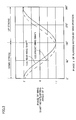
- FIG. 20 is a graph representing a relation between buoyancy and difference between the phase of flapping motion and phase of torsion angle, at various ground speeds.
- FIG. 21 is a graph representing a relation between thrust and difference between the phase of flapping motion and phase of torsion angle, at various ground speeds.
- FIG. 22 shows phase difference and amplitude difference of front and rear wing shafts when phase difference ⁇ is ⁇ 90°.
- FIG. 23 shows phase difference and amplitude difference of front and rear wing shafts when phase difference ⁇ is 0°.
- FIG. 24 shows phase difference and amplitude difference of front and rear wing shafts when phase difference ⁇ is 90°.
- FIG. 25 shows phase difference and amplitude difference of front and rear wing shafts when phase difference ⁇ is 180°, in accordance with a second embodiment.
- FIG. 26 is another graph representing a relation between buoyancy and difference between the phase of flapping motion and phase of torsion angle, at various ground speeds.
- FIG. 27 is another graph representing a relation between thrust and difference between the phase of flapping motion and phase of torsion angle, at various ground speeds.
- FIG. 1 shows the flapping apparatus having two wing shafts as the wing portion, in which (a) is a front view of the flapping apparatus and (b) is a left side view, viewed from the front face of the flapping apparatus.
- a right wing is also formed in mirror-symmetry with respect to the central axis 802 of a main body 105 .
- a main body axis 801 along the direction of extension of main body 105 is in a horizontal plane, and that the central axis 802 passing through the center of gravity extends along the vertical direction.
- a wing (left wing) is formed, which has a front wing shaft 103 and a rear wing shaft 104 and a wing film (main wing) 106 provided bridging across the front and rear wing shafts 103 and 104 .
- a rotary actuator 101 for driving front wing shaft 103 and a rotary actuator 102 for driving rear wing shaft 104 are mounted on main body 105 .
- Such an arrangement of actuators 101 and 102 as well as the shape of the wing including front wing shaft 103 , rear wing shaft 104 and wing film 106 are not limited to those described herein, provided that the flight function is assured.
- the position of center of gravity of the flapping apparatus is set to be lower than the point of application of the force received by the wing from ambient fluid to the actuator, to enhance stability of the flapping apparatus.
- the center of gravity and the point of application are substantially the same. In that case, difference of the force exerted by the fluid on the left and right wings necessary for attitude control becomes smaller, and hence change in attitude of the flapping apparatus becomes easier.
- Two rotary actuators 101 and 102 have a common axis of rotation 800 .
- the axis of rotation 800 forms a prescribed angle (90° ⁇ ) with the axis 801 of the main body.
- Front and rear wing shafts 103 and 104 perform a reciprocating operation in a plane that orthogonally crosses the axis of rotation 800 , with the actuator 101 , 102 being a fulcrum, respectively.
- the angle formed by the plane orthogonally crossing the axis of rotation 800 and the axis 801 of the main body is the elevation ⁇ .
- the elevation ⁇ is changed by an elevation control portion 108 .
- Elevation control portion 108 rotates support portions supporting rotary actuators 101 and 102 about a central axis of rotation extending in the left-right direction.
- front wing shaft 103 and rear wing shaft 104 rotate together with rotary actuators 101 and 102 about the central axis of rotation extending in the left-right direction.
- elevation ⁇ changes by the angle of rotation in proportion to the angle of rotation of elevation control portion 108 .
- elevation control portion 108 controls the angle of rotation, the angle formed by the plane including the trajectory of reciprocating operation of front wing shaft 103 or a plane including the trajectory of reciprocating operation of rear wing shaft 104 and a phantom reference plane including the front-rear direction and the left-right direction can be changed.
- main body 105 of the flapping apparatus should desirably be formed by polyethylene terephthalate (PET) molded to a cylindrical shape.
- PET polyethylene terephthalate
- the material and the shape of main body 105 are not limiting.
- An ultrasonic progressive wave actuator using a piezo-electric element is desirable as the actuators 101 and 102 , as it has large activation torque, enables reciprocating operation in a simple manner and has a simple structure.
- Such an actuator is classified into two types, that is, rotary actuator and linear actuator. In the example shown in (a) and (b) of FIG. 1 , rotary actuators are used.
- a method of directly driving the wing by an ultrasonic element using progressive wave will be mainly discussed in the following.
- the mechanism for driving the wing and the type of the actuator used therefor are not limited to those described with respect to the present embodiment.
- a rotary actuator 401 shown in FIG. 11 may be used, other than the rotary actuators 101 and 102 shown in (a) and (b) of FIG. 1 .
- a front wing shaft or a rear wing shaft 403 is attached to a rotary actuator 401 mounted on main body 404 .
- the front or rear wing shaft 403 performs a rotating operation about the rotation axis 402 of rotary actuator 401 . It is possible to have rotary actuators 101 and 102 to perform the rotating operation as described above, using a voice coil motor in place of rotary actuator 401 .
- a mechanism for driving the wing portion a mechanism having an exoskeleton structure and a linear actuator combined may be applied.
- a flapping apparatus employing such a mechanism is shown in FIGS. 12 and 13 .
- a front wing shaft or a rear wing shaft 503 is connected to one end of a linear actuator 501 .
- Motion of linear actuator 501 is transmitted to the front or rear wing shaft 503 through a hinge 502 attached to main body 504 , so that flapping motion occurs.
- the flapping motion is conceived from the flapping motion of a dragonfly, the wing of which is directly driven by the muscle.
- the main body is divided into an upper main body 603 and a lower main body 604 .
- Motion of a linear actuator 601 fixed on lower main body 604 is transmitted to upper main body 603 .
- the motion of upper main body 603 is transmitted to the front or rear wing shaft 603 through a hinge 602 as a fulcrum, and the flapping motion occurs.
- This flapping operation is conceived from the flapping operation of a bee, not the dragonfly.
- the front and rear wing shafts 603 on the left and right sides are simultaneously driven by one actuator 601 , and therefore, separate driving of left and right wing shafts is impossible. Therefore, delicate flight control of the flapping apparatus is impossible.
- the number of actuators can be reduced, weight and power consumption of the flapping apparatus can be reduced.
- front wing shaft 103 and rear wing shaft 104 are respectively connected to rotary actuators 101 and 102 .
- a wing film 106 is provided between the front and rear wing shafts 103 and 104 .
- the wing film 106 has initial stress in a direction of contraction in its plane, which serves to enhance stiffness of the entire wing.
- front and rear wing shafts 103 and 104 are formed to have a hollow structure, from carbon graphite.
- the front and rear wing shafts 103 and 104 have elasticity, and front and rear wing shafts 103 and 104 are deformable by the tension of wing film 106 .
- FIG. 14 shows an overall structure of the flapping apparatus of the present invention. The wing on the left side along the direction of progress (upward on the sheet) is not shown.
- an ultrasonic sensor 701 On main body 105 , an ultrasonic sensor 701 , an infrared sensor 702 , an acceleration sensor 703 and an angular acceleration sensor 704 are arranged. Results of detection by these sensors are transmitted to a flapping control portion 705 .
- Flapping control portion 705 processes information such as distance between the flapping apparatus and an obstacle or a person near the apparatus, from the results detected by the ultrasonic sensor 701 or infrared sensor 702 . Further, information such as the state of flight, target position or attitude of the flapping apparatus is processed from the results detected by acceleration sensor 703 or angular acceleration sensor 704 , and driving control of left and right actuators 101 and 102 and a center of gravity control portion 707 is determined. Reciprocating motions of front wing shaft 103 and rear wing shaft 104 are controlled accordingly. As a result, wing film 106 performs a prescribed flapping motion.
- ultrasonic sensor 701 and infrared sensor 702 are used as means for detecting an obstacle existing around the flapping apparatus and acceleration sensor 703 and angular acceleration sensor 704 are used as means for detecting position and attitude of the flapping apparatus, the sensors are not limited to these, and any sensor that can measure environmental conditions, position and attitude of the flapping apparatus may be used.
- the attitude of the flapping apparatus can be calculated from acceleration information obtained by arranging two acceleration sensors capable of measuring acceleration in three axial directions orthogonally crossing with each other, arranged at different positions of main body 105 . Further, it is possible to calculate position and attitude of the flapping apparatus by providing a magnetic field distribution in the space in which the flapping apparatus moves, and by detecting the magnetic field distribution by a magnetic sensor.
- sensors represented by acceleration sensor 703 and angular acceleration sensor 704 are shown as components separate from flapping control portion 705 .
- the sensors may be formed integrally with and on the same substrate as flapping control portion 705 by micromachining technique, for example.
- wing portion of the flapping apparatus is open-loop controlled
- closed-loop control is also possible by providing an angle sensor at a root of the wing portion and using angle information obtained from the angle sensor.
- the sensors listed above are not essential.
- Flapping control portion 705 is connected to a memory portion 708 , and existing data necessary for flapping control may be read from memory portion 708 . Further, information obtained by sensors 701 to 704 may be fed to memory portion 708 and information in memory portion 708 is rewritten as needed.
- the flapping apparatus may have a learning function.
- sensors 701 to 704 may be directly connected to memory portion 708 , not through flapping control portion 705 .
- flapping control portion 705 may be connected to communication control portion 709 , allowing data input to/output from communication control portion 709 .
- Communication control portion 709 transmits/receives data to/from an external apparatus through an antenna portion 710 .
- Such a communication function enables speedy transfer of data obtained by the flapping apparatus and stored in memory portion 708 to an external apparatus. Further, it is possible to receive from an external apparatus information that cannot be obtained by the flapping apparatus and to store such information in memory portion 708 , so that such information can be used for flapping control. Without storing a large amount of map information fully in the flapping apparatus, it is possible to obtain map information of a desired area as needed from a base station.
- antenna portion 710 is shown as a bar protruding from an end of main body 105 in the example shown in FIG. 14 , it may have any shape or arrangement provided that an antenna function is attained.
- a loop shaped antenna may be formed on the wing film 106 , utilizing front wing shaft 103 or rear wing shaft 104 .
- the antenna may be contained in main body 105 , or the antenna and communication control portion 709 may be integrated, in the flapping apparatus.
- Ultrasonic sensor 701 , infrared sensor 702 , acceleration sensor 703 , angular acceleration sensor 704 , flapping control portion 705 , left and right actuators 101 and 102 , center of gravity control portion 707 , memory portion 708 , communication control portion 709 and antenna portion 710 are driven by a current supplied from a power supply portion 711 .
- an internal combustion engine may be used.
- An actuator utilizing physiological oxidation-reduction reaction as can be seen in the muscle of insects may be used. Further, a method of obtaining energy for driving the actuator from the outside may be possible.
- a thermister thermoinoic element
- an electromagnetic wave or the like may be used for the electric power.
- One flapping operation means a down stroke of the wing followed by an up stroke of the wing.
- fluid force for down stroke a method by which the vertically upward fluid force acting on the wing in a down stroke (hereinafter referred to as “fluid force for down stroke”) is made larger than the vertically downward fluid force acting on the wing in an up stroke (hereinafter referred to as “fluid force for an up stroke”)
- fluid force for an up stroke a method by which the vertically upward fluid force acting on the wing in a down stroke
- fluid force for an up stroke a method by which the vertically upward fluid force acting on the wing in a down stroke
- fluid force for an up stroke a method of flapping corresponding to but simplified from the manner of flapping of an insect.
- weight The magnitude of the buoyancy obtained by the flapping method and the gravity acting on the flapping apparatus
- the down stroke should be such that the volume of a space in which the wing film 106 moves in the down stroke is maximized.
- the wing film 106 should be moved downward approximately parallel to the horizontal plane, whereby almost maximum fluid force can be obtained.
- the wing should be moved upward such that the volume of the space in which wing film 106 moves is minimized.
- the wing film 106 should be moved upward approximately at a right angle with respect to the horizontal plane, and the fluid force exerted on the wing is approximately minimized.
- the wing shafts 103 and 104 are rotated by an angle ⁇ (flapping angle) about the rotation axis 800 by rotary actuators 101 and 102 , respectively. Further, the reciprocating motion of rear wing shaft 104 is adapted to be delayed by a phase ⁇ from the reciprocating motion of the front wing shaft 103 .
- front wing shaft 103 of rotary actuator 101 which is at a higher position is moved downward earlier in the down stroke shown in FIGS. 3 to 7 , and therefore tip end portion 107 of the wing between the tip ends of front and rear wing shafts 103 and 104 comes closer to horizontal.
- the vector of the buoyancy inclines forward or backward by changing the phase difference ⁇ .
- the apparatus moves forward, when it is inclined backward, the apparatus moves backward and when it is directed directly upward, the apparatus hovers.
- flapping frequency f, or flapping angle ⁇ that can define the maximum angle (stroke angle) of front wing shaft 103 or rear wing shaft 104 , in addition to phase difference ⁇ .
- a prescribed phantom plane including two wing shafts when the phase ⁇ f of flapping motion of front wing shaft 103 and the phase ⁇ b of flapping motion of rear wing shaft 104 are the same is used as a reference, and an angle formed by the tip end portion 107 of the wing and the prescribed phantom plane is the torsion angle ⁇ .
- the front and rear wing shafts are elastic and deformable, and therefore, the torsion angle ⁇ may vary to some extent. Further, the angle is smaller closer to the root of the wing shaft.
- the angle ⁇ in accordance with the above equation will be used for the following discussion.
- a plane formed by the flapping motion of the tip end portion 107 of the wing generally referred to as a stroke plane
- a horizontal plane a plane vertical to the direction of gravity
- the prescribed phantom plane for defining the torsion angle ⁇ .
- What is important in the moving apparatus of the present invention is to change elevation of the wing portion during the flapping motion.
- torsion angle ⁇ is used as a physically equivalent parameter to the elevation.
- the abscissa represents the time corresponding to one period of flapping motion, as phase ⁇ .
- the former half of FIG. 15 represents a down stroke and the latter half an up stroke.
- Curves of the graphs represent changes with time of phase ⁇ f of the flapping motion of the front wing shaft 103 , phase ⁇ b of the flapping motion of the rear wing shaft 104 , torsion angle of the wing from a vertical plane ( ⁇ ), and vertical component (buoyancy) A and horizontal component (thrust) J of the fluid force.
- vertical component A (buoyancy) of the fluid force per unit time is larger in the down stroke than in the up stroke, and therefore, one wing provides vertically upward fluid force of about 500 dyn as an average for one period.
- the weight of the flapping apparatus is about 1 g or smaller, it can be lifted by two wings.
- the horizontal component J (thrust) of the fluid force per unit time is almost cancelled in one period, and hence, a flapping apparatus having the weight of about 1 g can hover.
- the flapping apparatus can move forward. At this time, for horizontal forward movement of the flapping apparatus, it is desired that the frequency f be reduced slightly. On the contrary, when the phase difference for the down stroke ⁇ is made smaller or the phase difference for the up stroke ⁇ is made larger, the apparatus can move backward. For horizontal backward movement, it is desired that the frequency f be increased slightly.
- the flapping apparatus can move horizontally forward at the speed of 1 m in the initial 1 second.
- the apparatus can move horizontally backward at the speed of about 1 m for the initial 1 second.
- the frequency f may be increased or decreased.
- upward movement and downward movement can be controlled mainly by the frequency f
- the flapping apparatus moves upward, and by lowering frequency f the flapping apparatus moves downward.
- the torsion angle ⁇ of the wing is slowly changed during an up stroke or a down stroke, in order to reduce load on the actuator.
- the torsion angle ⁇ may be set at a predetermined value during an up stroke or down stroke and the torsion angle ⁇ may be abruptly changed at the transition point from a down stroke to an up stroke or from an up stroke to the down stroke.
- This example shows a flapping motion conceived from the hovering of a humming bird. Steering to the left or to the right may be realized by generating a difference in thrust of left and right wings, if it is possible to separately control flapping motions of the left and right wings.
- the flapping angle ⁇ of the right wing should be made smaller than that of the left wing, or phase difference between the front wing shaft and the rear wing shaft of the right wing is made larger than that of the left wing, or alternatively, the flapping elevation ⁇ of the right wing should be made smaller than the left wing, if the flapping elevation ⁇ is controllable.
- the thrust of the right wing becomes lower relative to the thrust of the left wing, and hence the apparatus can turn to the right.
- the control is opposite.
- a center of gravity control portion 707 that is mounted in the flapping apparatus shown in FIG. 14 may be mounted in the present flapping apparatus so as to shift the center of gravity of the flapping apparatus to the left or to the right, to enable turning to the left or to the right.
- the flapping apparatus can turn to the right.
- the flapping apparatus can turn to the left.
- This method is also applicable when separate control of the two wings is possible.
- flapping frequency f for the left be set to the same value as the flapping frequency f for the right, so as to keep stable the attitude of the apparatus.
- these two planes are parallel to each other.
- the plane that includes the trajectory of reciprocating motion of the front wing shaft 103 and the plane that includes the trajectory of reciprocating motion of the rear wing shaft 104 may cross at an angle.
- the flapping angle of front wing shaft 103 is ⁇ + ⁇ /2
- the flapping angle of rear wing shaft 104 is ⁇ /2.
- amplitude difference between front wing shaft 103 and rear wing shaft 104 is ⁇ .
- the flapping angle refers to the maximum value or minimum value of the angle of rotation in the reciprocating motion of front wing shaft 103 or rear wing shaft 104 .
- the reciprocating motion of front wing shaft 103 is a motion (simple harmonic oscillation) represented by sin ( ⁇ + ⁇ /2), and the reciprocating motion of rear wing shaft 104 is a motion (simple harmonic oscillation) represented by sin ( ⁇ /2).
- phase difference between the front and rear wing shafts 103 and 104 is ⁇ .
- control portion can change the torsion angle ⁇ variously by independently changing the amplitude difference ⁇ and phase difference ⁇ , during the flapping motion.
- the torsion angle ⁇ makes a change that can be represented by a function ⁇ cos ⁇ shifted in phase by ⁇ 90° from the function sin ⁇ representing the flapping motion. Whether cos ⁇ has a positive or negative sign is determined dependent on whether the former (latter) term of equation (3) represents the motion of the front (rear) wing shaft or the rear (front) wing shaft.
- FIG. 18 shows the relation between the motion of front wing shaft 103 , motion of rear wing shaft 104 , and the change in torsion angle ⁇ , at the flapping angle ⁇ . From FIG. 18 , it can be seen that the maximum value ⁇ or minimum value ⁇ of the angle of rotation in the reciprocating motion of front or rear wing shaft 103 or 104 and the maximum value or minimum value of torsion angle ⁇ is shifted approximately by 90°.
- the torsion angle ⁇ changes in a manner represented by a function ⁇ sin ⁇ , which is of the same phase (0°) or opposite phase (180°) as the function sin ⁇ representing the flapping motion.
- sin ⁇ has a positive or negative sign is determined also dependent on whether the former (latter) term of equation (3) represents the motion of the front (rear) wing shaft or the rear (front) wing shaft.
- FIG. 19 shows the relation between the motion of front wing shaft 103 , motion of rear wing shaft 104 , and change in torsion angle ⁇ , at the flapping angle ⁇ . From FIG.
- the flapping apparatus can fly by the flapping motion even when both the phase difference ⁇ and amplitude difference ⁇ are changed.
- thrust J increases by as much as 34%.
- buoyancy A and thrust J can be given by the following equations, respectively.
- front wing shaft 103 or rear wing shaft 104 having the flapping angle ⁇ and the torsion angle ⁇ change in a manner represented by a sinusoidal wave, and during flapping motion, front wing shaft 103 and rear wing shaft 104 make motions at the same frequency f with phases shifted from each other by ⁇ .
- the abscissa represents phase difference ⁇ between the phase of reciprocating motion of front wing shaft 103 or rear wing shaft 104 reciprocating at a flapping angle of ⁇ and the phase of periodic change in torsion angle ⁇ .
- buoyancy A generated on the flapping apparatus increases.
- the phase difference ⁇ need not be fixed at 90° to lift an object of 1 g, as the buoyancy increases along with the increase of ground speed.
- the phase difference ⁇ can be changed within the range of 90° ⁇ 26°, when it is 4 m/s, within the range of 90° ⁇ 44°, when it is 6 m/s, within the range of 90° ⁇ 62°, when it is 8 m/s, within the range of 90° ⁇ 79°, and when it is 10 m/s, within the range of 90°+92°, as can be seen from FIG. 20 .
- the value ⁇ that attains the peak thrust J is 90° when the ground speed is 2 m/s or lower.
- ⁇ is within the range of 90° ⁇ 35°, when it is 6 m/s, within the range of 90° ⁇ 55°, when it is 8 m/s, within the range of 90° ⁇ 70°, and when it is 10 m/s, within the range of 90° ⁇ 75°.
- phase difference ⁇ shown in FIG. 20 . Therefore, it can be understood that the most efficient method of increasing ground speed without losing buoyancy is to change the phase difference ⁇ to be closer to the value attaining peak thrust J as the ground speed increases.
- FIGS. 22 to 25 show exemplary operations of front wing shaft 103 and rear wing shaft 104 having the phase difference ⁇ and amplitude difference ⁇ , with phase difference ⁇ being ⁇ 90°, 0°, 90° and 180°, respectively.
- the next problem is how to change the phase difference ⁇ .
- phase difference ⁇ When the phase difference ⁇ is to be changed, values of amplitude difference ⁇ and phase difference ⁇ corresponding to the desired phase difference ⁇ are input to equations (4) and (5). Consequently, it becomes possible to continuously change the phase difference ⁇ between the periodic changes of reciprocating motion of front wing shaft 103 with flapping angle ⁇ and the torsion angle ⁇ . As a result, smooth (efficient) transition from hovering to forward flight or backward flight becomes possible.
- buoyancy A and thrust J are defined as follows.
- results such as shown in FIGS. 26 and 27 can be attained.
- the abscissa represents phase difference ⁇ between the phase of reciprocating motion of front wing shaft 103 or rear wing shaft 104 reciprocating at a flapping angle of ⁇ and the phase of periodic change in torsion angle ⁇ .
- phase difference ⁇ need not be fixed at 90° to lift an object of 17 g, as the buoyancy increases along with the increase of ground speed.
- phase difference t mentioned above may be 90° ( ⁇ A of FIG.
- thrust J decreases because of wind pressure as the ground speed increases. It is noted, however, that even when the phase difference ⁇ is changed in the manner as described above ( ⁇ A ⁇ D: corresponding to FIG. 26 ), thrust J is kept positive until the ground speed reaches 3 m/s. When the thrust J attains 0, increase of the ground speed V stops, that is, acceleration of the flapping apparatus attains 0, and therefore, the speed of flight (velocity at which the flapping apparatus moves forward) is maintained.
- the most efficient method of increasing the ground speed without lowering buoyancy is to change the value of phase difference ⁇ without changing the frequency f or flapping angle ⁇ , until the ground speed V attains to a prescribed value (about 3 m/s in the example above).
- the moving apparatus in accordance with the present embodiment can also provide similar effects as attained by the moving apparatus of the second embodiment.
Landscapes
- Engineering & Computer Science (AREA)
- Aviation & Aerospace Engineering (AREA)
- Toys (AREA)
Abstract
Description
tan α=(w/l)·[sin(γ·cos τ)−sin {γ·cos(τ+φ)}]
F=(4/3)·π2 ρwγ 2 f 2 l 3·sin2 τ·cos(γ·cos τ)
By integrating this equation on τ, average F⊥ of one period is given by
F⊥=(1/6)·π3 ρwγ 2 f 2 l 3(3+cos γ).
It is noted that horizontal components acting on the left and right wing portions cancel each other when the left and right wing portions make the same motion.
L↑=F⊥·sin α↑·cos α↑
D↑=F⊥·sin2 α↑
for the up stroke, and
L↓=F⊥·sin α↓·cos α↓
D↓=F⊥·sin2 α↓
for the down stroke.
L=(L↑+L↓)/2=(F⊥/2)sin(α↑+α↓)cos(α↑−α↓)
D=(D↑+D↓)/2=(F⊥/2)sin(α↑+α↓)sin(α↑−α↓)
sin ε>{(w 2+8·l 2)1/2 −w}/(4·l)
α=(γ+Δγ/2)sin(τ+φ/2)−(γ−Δγ/2)sin(τ−φ/2)≈Δγ sin τ+γφ cos τ (3)
A=(16/45)·π2 ρwγ 2 f 2 l 3·cos θ·sin 2α·sin η·(4+cos γ)+(2/3)·πρwγfl 2 V sin 2θ[cos2 α(2+cos γ)+sin2 α·cos 2η·(6−cos γ)/5]
J=(16/45)·π2 ρwγ 2 f 2 l 3·sin θ·sin 2α·sin η·(4+cos γ)+(2/3)·πρwγfl 2 V cos 2θ[cos2 α(2+cos γ)+sin2 α·cos 2η·(6−cos γ)/5]
Δγ=α max·cos η (4)
γ·φ=α max.·sin η
∴φ=(α max./γ)·sin η (5)
Therefore, by changing the amplitude difference Δγ and phase difference φ in the manner as represented by equations (4) and (5), the phase difference η can be set to any value while keeping constant the maximum value α max. of torsion angle α.
A=(16/45)·π2 ρwγ 2 f 2 l 3·cos θ·sin 2α·sin η·(4+cos γ)+πρwlV 2·cos2 α·sin 2θ
J=(16/45)·π2 ρwγ 2 f 2 l 3·sin θ·sin 2α·sin η·(4+cos γ)−πρwlV 2(cos2 α·cos 2θ+1)
Claims (7)
Applications Claiming Priority (9)
| Application Number | Priority Date | Filing Date | Title |
|---|---|---|---|
| JP2004-186167 | 2004-06-24 | ||
| JP2004-186167(P) | 2004-06-24 | ||
| JP2004186167 | 2004-06-24 | ||
| JP2005-110117 | 2005-04-06 | ||
| JP2005-110117(P) | 2005-04-06 | ||
| JP2005110117 | 2005-04-06 | ||
| JP2005-176038 | 2005-06-16 | ||
| JP2005-176038(P) | 2005-06-16 | ||
| JP2005176038A JP4142034B2 (en) | 2004-06-24 | 2005-06-16 | Mobile device |
Publications (2)
| Publication Number | Publication Date |
|---|---|
| US20060060698A1 US20060060698A1 (en) | 2006-03-23 |
| US8210470B2 true US8210470B2 (en) | 2012-07-03 |
Family
ID=36072895
Family Applications (1)
| Application Number | Title | Priority Date | Filing Date |
|---|---|---|---|
| US11/166,743 Expired - Fee Related US8210470B2 (en) | 2004-06-24 | 2005-06-23 | Moving apparatus |
Country Status (2)
| Country | Link |
|---|---|
| US (1) | US8210470B2 (en) |
| JP (1) | JP4142034B2 (en) |
Cited By (3)
| Publication number | Priority date | Publication date | Assignee | Title |
|---|---|---|---|---|
| US20150008279A1 (en) * | 2009-06-05 | 2015-01-08 | Aerovironment, Inc. | Air Vehicle Flight Mechanism and Control Method |
| US10017248B2 (en) * | 2014-04-28 | 2018-07-10 | University Of Maryland, College Park | Flapping wing aerial vehicles |
| US10065737B2 (en) | 2011-02-16 | 2018-09-04 | Aerovironment, Inc. | Air vehicle flight mechanism and control method for non-sinusoidal wing flapping |
Families Citing this family (11)
| Publication number | Priority date | Publication date | Assignee | Title |
|---|---|---|---|---|
| WO2008108892A1 (en) * | 2006-10-30 | 2008-09-12 | Kyriacos Zachary | Inverting wing propulsion system |
| US20100295303A1 (en) * | 2009-05-21 | 2010-11-25 | Makani Power, Inc. | Tethered system for power generation |
| JP5688700B2 (en) * | 2009-05-26 | 2015-03-25 | 国立大学法人 千葉大学 | MOBILE BODY CONTROL DEVICE AND MOBILE BODY HAVING MOBILE BODY CONTROL DEVICE |
| KR101193242B1 (en) | 2010-10-05 | 2012-10-18 | 국방과학연구소 | Method for flight control of ornithopter, apparatus for flight control of ornithopter and ornithopter having the same |
| WO2012112939A1 (en) * | 2011-02-17 | 2012-08-23 | Georgia Tech Research Corporation | Hovering and gliding multi-wing flapping micro aerial vehicle |
| JP5857658B2 (en) * | 2011-11-17 | 2016-02-10 | 学校法人早稲田大学 | Flapping robot |
| CN103523221B (en) * | 2013-10-11 | 2015-11-18 | 南京航空航天大学 | With the bionic Aircraft that active twist controls |
| CN104260886B (en) * | 2014-09-26 | 2016-08-17 | 北京航空航天大学 | A kind of micro flapping wing air vehicle imitative feather cracking lift-rising mechanism |
| CN104260887B (en) * | 2014-09-29 | 2016-11-23 | 上海交通大学 | Variable resonance frequency electromagnetic drive-type Dual Drive micro air vehicle with flapping-wing |
| CN105314109B (en) * | 2015-09-09 | 2017-10-10 | 吴立群 | A kind of wing drive mechanism of flapping wing aircraft |
| JP7254347B2 (en) * | 2019-08-27 | 2023-04-10 | 国立研究開発法人宇宙航空研究開発機構 | Morphing wing, flight control device, flight control method, and program |
Citations (22)
| Publication number | Priority date | Publication date | Assignee | Title |
|---|---|---|---|---|
| US2578845A (en) * | 1947-01-23 | 1951-12-18 | Schmidt William | Beating wing propelled aircraft |
| JPH05282040A (en) | 1992-03-31 | 1993-10-29 | Toshiba Corp | Automatic running robot |
| JPH0699369A (en) | 1992-07-23 | 1994-04-12 | Hitachi Ltd | Multileg walking mechanism and attitude control method thereof |
| JPH06305455A (en) | 1993-04-22 | 1994-11-01 | Osaka Gas Co Ltd | Crawler type travel device |
| JPH09272083A (en) | 1996-04-08 | 1997-10-21 | Mitsubishi Electric Corp | Two-foot walking robot |
| US5993286A (en) * | 1999-04-27 | 1999-11-30 | Tacquard; Timothy L. | Walking insect and method of assembling the same |
| US6082671A (en) * | 1998-04-17 | 2000-07-04 | Georgia Tech Research Corporation | Entomopter and method for using same |
| JP2000317148A (en) | 1999-05-10 | 2000-11-21 | Yohei Takatani | Double-wing flapping airplane |
| US6206324B1 (en) * | 1999-08-30 | 2001-03-27 | Michael J. C. Smith | Wing-drive mechanism, vehicle employing same, and method for controlling the wing-drive mechanism and vehicle employing same |
| US6227483B1 (en) * | 2000-04-05 | 2001-05-08 | SUCCESSION CLéMENT THERRIAULT | Wing movement for ornithopters and apparatus of the like |
| US6250585B1 (en) * | 1997-09-05 | 2001-06-26 | Nekton Technologies, Inc. | Impellers with bladelike elements and compliant tuned transmission shafts and vehicles including same |
| US6321480B1 (en) * | 1999-02-10 | 2001-11-27 | Walter Solomon | Self-propelled waterfowl decoy |
| US6339894B1 (en) * | 1999-02-10 | 2002-01-22 | Walter Solomon | Waterfowl decoy with interchangeable movable appendages |
| US20020117583A1 (en) * | 2001-02-27 | 2002-08-29 | Masaki Hamamoto | Moving apparatus |
| JP2003135866A (en) | 2001-11-08 | 2003-05-13 | Sharp Corp | Driving mechanism and wing-flapping flying machine |
| US6565039B2 (en) * | 2001-03-19 | 2003-05-20 | Michael J. C. Smith | Wing-drive mechanism and vehicle employing same |
| US6574903B2 (en) * | 2001-04-24 | 2003-06-10 | Walter Solomon | Waterfowl decoy with realistic motion and interchangeable wings and feet |
| US6783097B1 (en) * | 2004-01-12 | 2004-08-31 | Michael J. C. Smith | Wing-drive mechanism and vehicle employing same |
| US6926230B2 (en) * | 2003-01-16 | 2005-08-09 | Sharp Kabushiki Kaisha | Flapping apparatus |
| US20050230522A1 (en) * | 2004-01-12 | 2005-10-20 | Smith Michael J C | Wing-drive mechanism and vehicle employing same |
| US6974356B2 (en) * | 2003-05-19 | 2005-12-13 | Nekton Research Llc | Amphibious robot devices and related methods |
| US7089084B2 (en) * | 2002-05-27 | 2006-08-08 | Sharp Kabushiki Kaisha | Search robot system |
-
2005
- 2005-06-16 JP JP2005176038A patent/JP4142034B2/en not_active Expired - Fee Related
- 2005-06-23 US US11/166,743 patent/US8210470B2/en not_active Expired - Fee Related
Patent Citations (24)
| Publication number | Priority date | Publication date | Assignee | Title |
|---|---|---|---|---|
| US2578845A (en) * | 1947-01-23 | 1951-12-18 | Schmidt William | Beating wing propelled aircraft |
| JPH05282040A (en) | 1992-03-31 | 1993-10-29 | Toshiba Corp | Automatic running robot |
| JPH0699369A (en) | 1992-07-23 | 1994-04-12 | Hitachi Ltd | Multileg walking mechanism and attitude control method thereof |
| JPH06305455A (en) | 1993-04-22 | 1994-11-01 | Osaka Gas Co Ltd | Crawler type travel device |
| JPH09272083A (en) | 1996-04-08 | 1997-10-21 | Mitsubishi Electric Corp | Two-foot walking robot |
| US6250585B1 (en) * | 1997-09-05 | 2001-06-26 | Nekton Technologies, Inc. | Impellers with bladelike elements and compliant tuned transmission shafts and vehicles including same |
| US6082671A (en) * | 1998-04-17 | 2000-07-04 | Georgia Tech Research Corporation | Entomopter and method for using same |
| US6339894B1 (en) * | 1999-02-10 | 2002-01-22 | Walter Solomon | Waterfowl decoy with interchangeable movable appendages |
| US6321480B1 (en) * | 1999-02-10 | 2001-11-27 | Walter Solomon | Self-propelled waterfowl decoy |
| US5993286A (en) * | 1999-04-27 | 1999-11-30 | Tacquard; Timothy L. | Walking insect and method of assembling the same |
| JP2000317148A (en) | 1999-05-10 | 2000-11-21 | Yohei Takatani | Double-wing flapping airplane |
| US6206324B1 (en) * | 1999-08-30 | 2001-03-27 | Michael J. C. Smith | Wing-drive mechanism, vehicle employing same, and method for controlling the wing-drive mechanism and vehicle employing same |
| US6227483B1 (en) * | 2000-04-05 | 2001-05-08 | SUCCESSION CLéMENT THERRIAULT | Wing movement for ornithopters and apparatus of the like |
| US20020117583A1 (en) * | 2001-02-27 | 2002-08-29 | Masaki Hamamoto | Moving apparatus |
| JP2002326599A (en) | 2001-02-27 | 2002-11-12 | Sharp Corp | Moving device |
| US6840477B2 (en) * | 2001-02-27 | 2005-01-11 | Sharp Kabushiki Kaisha | Fluttering wing-operated flying moving apparatus |
| US6565039B2 (en) * | 2001-03-19 | 2003-05-20 | Michael J. C. Smith | Wing-drive mechanism and vehicle employing same |
| US6574903B2 (en) * | 2001-04-24 | 2003-06-10 | Walter Solomon | Waterfowl decoy with realistic motion and interchangeable wings and feet |
| JP2003135866A (en) | 2001-11-08 | 2003-05-13 | Sharp Corp | Driving mechanism and wing-flapping flying machine |
| US7089084B2 (en) * | 2002-05-27 | 2006-08-08 | Sharp Kabushiki Kaisha | Search robot system |
| US6926230B2 (en) * | 2003-01-16 | 2005-08-09 | Sharp Kabushiki Kaisha | Flapping apparatus |
| US6974356B2 (en) * | 2003-05-19 | 2005-12-13 | Nekton Research Llc | Amphibious robot devices and related methods |
| US6783097B1 (en) * | 2004-01-12 | 2004-08-31 | Michael J. C. Smith | Wing-drive mechanism and vehicle employing same |
| US20050230522A1 (en) * | 2004-01-12 | 2005-10-20 | Smith Michael J C | Wing-drive mechanism and vehicle employing same |
Cited By (8)
| Publication number | Priority date | Publication date | Assignee | Title |
|---|---|---|---|---|
| US20150008279A1 (en) * | 2009-06-05 | 2015-01-08 | Aerovironment, Inc. | Air Vehicle Flight Mechanism and Control Method |
| US9950790B2 (en) * | 2009-06-05 | 2018-04-24 | Aerovironment, Inc. | Air vehicle flight mechanism and control method |
| US9957044B2 (en) | 2009-06-05 | 2018-05-01 | Aerovironment, Inc. | Air vehicle flight mechanism and control method |
| US10266258B2 (en) | 2009-06-05 | 2019-04-23 | Aerovironment, Inc. | Air vehicle flight mechanism and control method |
| US10919623B2 (en) | 2009-06-05 | 2021-02-16 | Aerovironment, Inc. | Air vehicle flight mechanism and control method |
| US10065737B2 (en) | 2011-02-16 | 2018-09-04 | Aerovironment, Inc. | Air vehicle flight mechanism and control method for non-sinusoidal wing flapping |
| US10850837B2 (en) | 2011-02-16 | 2020-12-01 | Aerovironment, Inc. | Air vehicle flight mechanism and control method for non-sinusoidal wing flapping |
| US10017248B2 (en) * | 2014-04-28 | 2018-07-10 | University Of Maryland, College Park | Flapping wing aerial vehicles |
Also Published As
| Publication number | Publication date |
|---|---|
| US20060060698A1 (en) | 2006-03-23 |
| JP4142034B2 (en) | 2008-08-27 |
| JP2006312436A (en) | 2006-11-16 |
Similar Documents
| Publication | Publication Date | Title |
|---|---|---|
| US8210470B2 (en) | Moving apparatus | |
| US6840477B2 (en) | Fluttering wing-operated flying moving apparatus | |
| US9290268B2 (en) | Hovering and gliding multi-wing flapping micro aerial vehicle | |
| US10017248B2 (en) | Flapping wing aerial vehicles | |
| JP4087104B2 (en) | Group robot system | |
| Kohut et al. | Aerodynamic steering of a 10 cm high-speed running robot | |
| US6422509B1 (en) | Tracking device | |
| JP4007947B2 (en) | Group robot system, sensing robot included in group robot system, base station included in group robot system, and control robot included in group robot system | |
| US7270589B1 (en) | Resilient leg design for hopping running and walking machines | |
| Chukewad et al. | A new robot fly design that is easier to fabricate and capable of flight and ground locomotion | |
| JP4651645B2 (en) | Group robot system | |
| JP3989943B2 (en) | Flapping levitation moving device | |
| JP3920076B2 (en) | Flapping flight equipment | |
| JP4467442B2 (en) | Mobile device | |
| JP2007253946A (en) | Robot system, flapping device used for it and flapping flight controller | |
| JP4540639B2 (en) | Takeoff and landing assistance device | |
| JP2003127995A (en) | Takeoff/landing assisting mechanism, takeoff/landing assisting device and levitating device subjected to takeoff/landing assistance | |
| JP3989707B2 (en) | Robot system, flapping apparatus and flapping flight control apparatus used therefor | |
| Tu et al. | Crawl and fly: A bio-inspired robot utilizing unified actuation for hybrid aerial-terrestrial locomotion | |
| JP2003162326A (en) | Group robot system, sensing robot used therefor, base station and pheromone robot | |
| JP4121970B2 (en) | Mobile device | |
| JP2005173968A (en) | Tracking robot system and tracking robot used therefor | |
| JP4294454B2 (en) | Flapping equipment | |
| JP4007940B2 (en) | Group robot system, sensing robot included in the group robot system, base station included in the group robot system, and control robot included in the group robot system | |
| JP2005125466A (en) | Group robot system, sensing robot included in group robot system, base station included in group robot system and pheromone robot included in group robot system |
Legal Events
| Date | Code | Title | Description |
|---|---|---|---|
| AS | Assignment |
Owner name: SHARP KABUSHIKI KAISHA, JAPAN Free format text: ASSIGNMENT OF ASSIGNORS INTEREST;ASSIGNORS:OHTA, YOSHIJI;HARA, KEITA;HAMAMAOTO, MASAKI;REEL/FRAME:016919/0651 Effective date: 20050809 |
|
| STCF | Information on status: patent grant |
Free format text: PATENTED CASE |
|
| FEPP | Fee payment procedure |
Free format text: PAYOR NUMBER ASSIGNED (ORIGINAL EVENT CODE: ASPN); ENTITY STATUS OF PATENT OWNER: LARGE ENTITY |
|
| FPAY | Fee payment |
Year of fee payment: 4 |
|
| FEPP | Fee payment procedure |
Free format text: MAINTENANCE FEE REMINDER MAILED (ORIGINAL EVENT CODE: REM.); ENTITY STATUS OF PATENT OWNER: LARGE ENTITY |
|
| LAPS | Lapse for failure to pay maintenance fees |
Free format text: PATENT EXPIRED FOR FAILURE TO PAY MAINTENANCE FEES (ORIGINAL EVENT CODE: EXP.); ENTITY STATUS OF PATENT OWNER: LARGE ENTITY |
|
| STCH | Information on status: patent discontinuation |
Free format text: PATENT EXPIRED DUE TO NONPAYMENT OF MAINTENANCE FEES UNDER 37 CFR 1.362 |
|
| FP | Lapsed due to failure to pay maintenance fee |
Effective date: 20200703 |