US8159161B2 - Motor control device - Google Patents
Motor control device Download PDFInfo
- Publication number
- US8159161B2 US8159161B2 US12/543,802 US54380209A US8159161B2 US 8159161 B2 US8159161 B2 US 8159161B2 US 54380209 A US54380209 A US 54380209A US 8159161 B2 US8159161 B2 US 8159161B2
- Authority
- US
- United States
- Prior art keywords
- axis
- current
- motor
- voltage
- estimation
- Prior art date
- Legal status (The legal status is an assumption and is not a legal conclusion. Google has not performed a legal analysis and makes no representation as to the accuracy of the status listed.)
- Active, expires
Links
Images

Classifications
-
- H—ELECTRICITY
- H02—GENERATION; CONVERSION OR DISTRIBUTION OF ELECTRIC POWER
- H02P—CONTROL OR REGULATION OF ELECTRIC MOTORS, ELECTRIC GENERATORS OR DYNAMO-ELECTRIC CONVERTERS; CONTROLLING TRANSFORMERS, REACTORS OR CHOKE COILS
- H02P6/00—Arrangements for controlling synchronous motors or other dynamo-electric motors using electronic commutation dependent on the rotor position; Electronic commutators therefor
- H02P6/14—Electronic commutators
- H02P6/16—Circuit arrangements for detecting position
- H02P6/18—Circuit arrangements for detecting position without separate position detecting elements
- H02P6/185—Circuit arrangements for detecting position without separate position detecting elements using inductance sensing, e.g. pulse excitation
-
- H—ELECTRICITY
- H02—GENERATION; CONVERSION OR DISTRIBUTION OF ELECTRIC POWER
- H02P—CONTROL OR REGULATION OF ELECTRIC MOTORS, ELECTRIC GENERATORS OR DYNAMO-ELECTRIC CONVERTERS; CONTROLLING TRANSFORMERS, REACTORS OR CHOKE COILS
- H02P21/00—Arrangements or methods for the control of electric machines by vector control, e.g. by control of field orientation
- H02P21/14—Estimation or adaptation of machine parameters, e.g. flux, current or voltage
- H02P21/18—Estimation of position or speed
-
- H—ELECTRICITY
- H02—GENERATION; CONVERSION OR DISTRIBUTION OF ELECTRIC POWER
- H02P—CONTROL OR REGULATION OF ELECTRIC MOTORS, ELECTRIC GENERATORS OR DYNAMO-ELECTRIC CONVERTERS; CONTROLLING TRANSFORMERS, REACTORS OR CHOKE COILS
- H02P21/00—Arrangements or methods for the control of electric machines by vector control, e.g. by control of field orientation
- H02P21/24—Vector control not involving the use of rotor position or rotor speed sensors
- H02P21/32—Determining the initial rotor position
-
- H—ELECTRICITY
- H02—GENERATION; CONVERSION OR DISTRIBUTION OF ELECTRIC POWER
- H02P—CONTROL OR REGULATION OF ELECTRIC MOTORS, ELECTRIC GENERATORS OR DYNAMO-ELECTRIC CONVERTERS; CONTROLLING TRANSFORMERS, REACTORS OR CHOKE COILS
- H02P6/00—Arrangements for controlling synchronous motors or other dynamo-electric motors using electronic commutation dependent on the rotor position; Electronic commutators therefor
- H02P6/14—Electronic commutators
- H02P6/16—Circuit arrangements for detecting position
- H02P6/18—Circuit arrangements for detecting position without separate position detecting elements
- H02P6/183—Circuit arrangements for detecting position without separate position detecting elements using an injected high frequency signal
-
- H—ELECTRICITY
- H02—GENERATION; CONVERSION OR DISTRIBUTION OF ELECTRIC POWER
- H02P—CONTROL OR REGULATION OF ELECTRIC MOTORS, ELECTRIC GENERATORS OR DYNAMO-ELECTRIC CONVERTERS; CONTROLLING TRANSFORMERS, REACTORS OR CHOKE COILS
- H02P2203/00—Indexing scheme relating to controlling arrangements characterised by the means for detecting the position of the rotor
- H02P2203/11—Determination or estimation of the rotor position or other motor parameters based on the analysis of high frequency signals
Definitions
- the present invention relates to a motor control device for controlling operation of a motor.
- the present invention also relates to a motor drive system and electrical equipment that utilizes the motor control device.
- the applicant also previously proposed a method utilizing application of a high-frequency voltage (see Japanese Patent Laid-Open No. 2007-53829).
- estimated axes for control corresponding to a d-axis and a q-axis are set as a ⁇ -axis and a d-axis respectively, and a high-frequency rotation voltage or alternating voltage on the ⁇ coordinate system is applied to a motor.
- a magnetic pole position is estimated based on a derived product of ⁇ -axis and d-axis components of a high-frequency current that flows through the motor due to application of the high-frequency voltage.
- an axial error ⁇ is estimated under the approximation that the axial error ⁇ between the d-axis and the ⁇ -axis as an estimation axis is close to zero, and therefore, it is necessary that the ⁇ -axis as an estimation axis and the d-axis corresponding to the magnetic pole position coincide with each other.
- the estimation takes a certain amount of time.
- an object of the invention is to provide a motor control device, a motor control system, and equipment which contribute to shortening the time required in estimating the magnetic pole position (the initial magnetic pole position) to control operation of a motor.
- One aspect of the invention is a motor control device for controlling a motor based on an estimated magnetic pole position
- the motor control device including a voltage applying unit for applying a voltage for estimation having a predetermined frequency to a motor; a current detection unit for detecting a current that flows through the motor in response to the application of the voltage; and a magnetic pole position estimation unit for estimating a magnetic pole position at a rotor of the motor based on the current detected by the current detection unit; in which the magnetic pole position estimation unit includes an estimation processing unit for deriving from first and second axis components of the current detected by the current detection unit: a first axis component, a second axis component, a third axis component, and a fourth axis component of a current for estimation that flows through the motor in response to application of the voltage for estimation, and estimating the magnetic pole position based on the first to the fourth axis components of the current for estimation; and in which in an electric angle expression, the first axis and the second axis are orthogonal to
- the third axis and the fourth axis are for example shifted by p/4 in electric angle from the first axis and the second axis.
- the estimation processing unit may derive the first axis component and the second axis component of the current for estimation by extracting a predetermined frequency component from the first axis component and the second axis component of the current detected by the current detection unit, and may derive the third axis component and the fourth axis component of the current for estimation by utilizing a sum and a difference of the first axis component and the second axis component of the current for estimation.
- the estimation processing unit may estimate the magnetic pole position based on a product of the first axis component and the second axis component of the current for estimation, and a product of the third axis component and the fourth axis component of the current for estimation.
- the estimation processing unit may estimate the magnetic pole position based on a direct current component of a product of the first axis component and the second axis component of the current for estimation, and a direct current component of a product of the third axis component and the fourth axis component of the current for estimation.
- the estimation processing unit may estimate the magnetic pole position by dividing the direct current component of the product of the first axis component and the second axis component of the current for estimation by a value including the direct current component of the product of the third axis component and the fourth axis component of the current for estimation.
- the estimation processing unit may derive the product of the third axis component and the fourth axis component of the current for estimation by utilizing square information of each of the first axis component and the second axis component of the current for estimation.
- the magnetic pole position estimated by utilizing the estimation processing unit may be treated as an initial magnetic pole position, and a subsequent magnetic pole position may be estimated based on such an initial magnetic pole position by a second estimation processing unit that is different from the estimation processing unit.
- the first axis may be an estimated axis for control corresponding to the d-axis of the rotor or a predetermined fixed axis.
- Another aspect of the invention is a motor drive system having a motor, an inverter for driving rotation of the motor, and the motor control device as described above that controls the motor by controlling the inverter.
- Still another aspect of the invention is electrical equipment having the motor drive system that operates by utilizing torque of a motor within the motor drive system.
- the electrical equipment for example could be an electric vehicle, an air conditioner, a washing machine, a drying machine, etc.
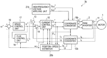
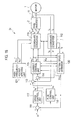
- FIG. 1 is a block diagram showing the general structure of a motor drive system according to one embodiment of the present invention.
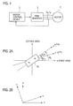
- FIGS. 2A and 2B are analytical model diagrams of the motor of FIG. 1 .
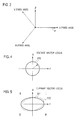
- FIG. 3 is a graph showing U-phase, V-phase, and W-phase armature winding fixed axes and a and ⁇ fixed axes concerning the motor of FIG. 1 .
- FIG. 4 is a diagram showing a voltage vector locus of a perfect circle rotation voltage that may be applied to the motor of FIG. 1 .
- FIG. 5 is a diagram showing a current vector locus of a current that flows in the motor caused by applying the perfect circle rotation voltage.
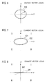
- FIG. 6 is a diagram showing a voltage vector locus of an ellipsoidal rotation voltage that may be applied to the motor of FIG. 1 .
- FIG. 7 is a diagram showing a current vector locus of a current that flows in the motor caused by applying the ellipsoidal rotation voltage.
- FIG. 8 is a diagram showing a current vector locus of a current that flows in the motor caused by applying an alternating voltage in the ⁇ -axis direction.
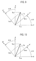
- FIG. 9 is a diagram showing a phase relationship of the ⁇ -axis, the d-axis, the ⁇ ′-axis, and the d′-axis.
- FIG. 10 is a diagram showing a phase relationship of the a-axis, the ⁇ -axis, the a′-axis, and the ⁇ ′-axis.
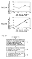
- FIGS. 11A-11C are diagrams showing simulation results concerning axial error estimation.
- FIGS. 12A-12C are diagrams showing simulation results concerning axial error estimation.
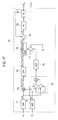
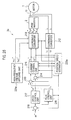
- FIG. 13 is a block diagram of the motor drive system according to a first embodiment of the present invention.
- FIG. 14 is a block diagram of an estimation processing unit of the position/speed estimator of FIG. 13 .
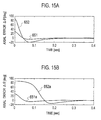
- FIGS. 15A and 15B are diagrams concerning the first embodiment of the present invention showing simulation results of axial error estimation.
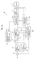
- FIG. 16 is a block diagram of the motor drive system according to a second embodiment of the present invention.
- FIG. 17 is a block diagram of an estimation processing unit of the position/speed estimator of FIG. 16 .
- FIG. 18 is a block diagram of the motor drive system according to a third embodiment of the present invention.
- FIG. 19 is a diagram concerning the third embodiment of the present invention showing a phase relationship of the d-axis, the q-axis, the dc-axis, and the qc-axis.
- FIG. 20 is a block diagram of an estimation processing unit in the position/speed estimator of FIG. 18 .
- FIGS. 21A and 21B are diagrams concerning the third embodiment of the present invention showing simulation results of magnetic pole position estimation.
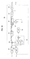
- FIG. 22 is an operation flowchart of the motor drive system according to a fourth embodiment of the present invention.
- FIG. 23 is a block diagram of the motor drive system according to the fourth embodiment of the present invention.
- FIG. 24 is a block diagram of the position/speed estimator of FIG. 23 .
- FIG. 25 is a block diagram of the motor drive system according to a fifth embodiment of the present invention.
- FIG. 26 is a block diagram of the position/speed estimator of FIG. 25 .
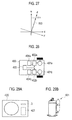
- FIG. 27 is a diagram concerning a sixth embodiment of the present invention showing a current vector on a rotating coordinate system at the time of performing a synchronized operation.
- FIG. 28 is a block diagram of an electric vehicle according to an eighth embodiment of the present invention.
- FIG. 29A is an outline view of an air conditioning machine according to the eighth embodiment of the present invention and FIG. 29B is an outline view of a compressor provided in the air conditioning machine.
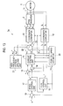
- FIG. 1 is a general block diagram of a motor drive system according to a first embodiment of the present invention.
- the motor drive system of FIG. 1 includes a motor 1 , a PWM (Pulse Width Modulation) inverter 2 , and a motor control device 3 .
- control is performed without a position sensor, in which instead a magnetic pole position (a rotor position) of a rotor of the motor 1 is detected by an estimation procedure rather than utilizing a position signal from a position sensor.
- the motor 1 is a three-phase permanent magnet synchronous motor and includes a rotor (not shown) with a permanent magnet and a stator (not shown) with three-phase armature windings.
- the motor 1 is a salient pole machine such as an interior permanent magnet synchronous motor.
- the PWM inverter (hereinafter referred to simply as “inverter”) 2 supplies the motor 1 with a three-phase alternating voltage under control of the motor control device 3 .
- the three-phase alternating voltage applied to the motor 1 by the inverter 2 consists of a U-phase voltage v u which represents a voltage applied to the U-phase armature winding, a V-phase voltage v v which represents a voltage applied to the V-phase armature winding, and a W-phase voltage v w which represents a voltage applied to the W-phase armature winding.
- the entire voltage applied to the motor 1 which is a combined voltage of the U-phase voltage v u , the V-phase voltage v v , and the W-phase voltage v w , will be referred to as a motor voltage (motor terminal voltage) and will be represented by the symbol V a .
- the U-phase component, V-phase component, and W-phase component of the current supplied to the motor 1 from the inverter 2 by the application of the motor voltage V a that is, the current that flows through the U-phase, V-phase, and W-phase armature windings will be called a U-phase current i u , a V-phase current i v , and a W-phase current i w respectively.
- the entire current supplied to the motor 1 which is a combined current of the U-phase current i u , the V-phase current i v , and the W-phase current i w , will be called a motor current (armature current) and will be represented by the symbol I a .
- the motor control device 3 provides PWM signals for achieving a desired control of the motor rotation (such as a vector control) to the inverter 2 while being based on a detected value of the motor current I a .
- FIGS. 2A and 2B are analytical model diagrams of the motor 1 .
- armature windings mean the ones provided in the motor 1 .
- FIG. 2A the a-axis and the ⁇ -axis are shown, which are fixed axes that are fixed regardless of the rotation of the motor 1 .
- the a-axis coincides with the U-phase armature winding fixed axis, for example, as shown in FIG. 3 .
- the a-axis and the U-phase armature winding fixed axis may be different.
- the ⁇ -axis is an axis with its phase being advanced by 90 degrees in electric angle from the a-axis.
- FIG. 3 shows the U-phase, V-phase, and W-phase armature winding fixed axes as well as the a-axis and the ⁇ -axis.
- the counterclockwise rotation direction corresponds to a phase advancement.
- reference numeral 1 a denotes a permanent magnet provided at a rotor of the motor 1 .
- the axis that follows the direction of the magnetic flux created by the permanent magnet 1 a is set as the d-axis.
- the direction of the d-axis coincides with the direction of the magnetic flux created by the permanent magnet 1 a .
- an estimated axis for control corresponding to the d-axis is set as the ⁇ -axis.
- the ⁇ -axis is defined at the motor control device 3 for controlling the motor 1 .
- FIG. 1 a denotes a permanent magnet provided at a rotor of the motor 1 .
- the axis whose phase is advanced by 90 degrees in electric angle from the d-axis is set as the q-axis
- the axis whose phase is advanced by 90 degrees in electric angle from the ⁇ -axis is set as the d-axis.
- the a-axis and the ⁇ -axis will be called collectively as a ⁇ axes and the coordinate system that takes the a-axis and the ⁇ -axis as its coordinate axes will be called the a ⁇ coordinate system.
- the d-axis and the q-axis will be called collectively as the dq axes and the coordinate system that takes the d-axis and the q-axis as its coordinate axes will be called the dq coordinate system.
- the ⁇ -axis and the d-axis will be called collectively as ⁇ axes and the coordinate system that takes the ⁇ -axis and the d-axis as its coordinate axes will be called the ⁇ coordinate system.
- the a ⁇ coordinate system is a fixed coordinate system, but the dq coordinate system and the ⁇ coordinate system are rotating coordinate systems.
- the rotation speed of the dq axes and the dq coordinate system is expressed as ⁇ d and the rotation speed of the ⁇ axes and the ⁇ coordinate system is expressed as ⁇ .
- the angle (phase) of the d-axis from the a-axis is denoted by ⁇ d and the angle (phase) of the ⁇ -axis from the a-axis is denoted by ⁇ ⁇ .
- the angles represented by ⁇ d and ⁇ y are angles in electric phase angle
- the rotation speeds represented by ⁇ d and ⁇ are angular speeds in electric phase angle.
- ⁇ d also is called a magnetic pole position (or a rotor position).
- ⁇ represents an estimated magnetic pole position (estimation for the magnetic pole position ⁇ d ) and ⁇ represents an estimated rotation speed (estimation for the rotation speed ⁇ d ).
- the d-axis component, the q-axis component, the ⁇ -axis component, the d-axis component, the a-axis component, and the ⁇ -axis component of the motor voltage V a will be referred to respectively a d-axis voltage, a q-axis voltage, a ⁇ -axis voltage, a d-axis voltage, an a-axis voltage, and a ⁇ -axis voltage, and will be represented by the symbols v d , v q , v ⁇ , vd, va and v ⁇ .
- the d-axis component, the q-axis component, the ⁇ -axis component, the d-axis component, the a-axis component, and the ⁇ -axis component of the motor current i will be referred to respectively as a d-axis current, a q-axis current, a ⁇ -axis current, a d-axis current, an a-axis current, and a ⁇ -axis current, and will be represented by the symbols i d , i q , i ⁇ , id, ia and i ⁇ .
- F a represents flux-linkage of the armature windings by the permanent magnet 1 a.
- L d and L q respectively represent d-axis inductance (the d-axis component of armature winding inductance) and q-axis inductance (the q-axis component of armature winding inductance).
- R a represents a resistance value per phase of the armature winding.
- F a , L d , L q , and P n are predetermined according to the characteristics of the motor 1 and are utilized as parameters for control of the motor drive system.
- Target values for the ⁇ -axis voltage v ⁇ and the d-axis voltage vd that the ⁇ -axis voltage v ⁇ and the d-axis voltage vd are to follow are represented by a ⁇ -axis voltage command value v ⁇ * and a d-axis voltage command value vd* respectively.
- Target values for the ⁇ -axis current i ⁇ and the d-axis current id that the ⁇ -axis current i ⁇ and the d-axis current id are to follow are represented by a ⁇ -axis current command value i ⁇ * and a d-axis current command value id* respectively.
- a target value for the rotation speed ⁇ (or ⁇ d ) that the rotation speed ⁇ (or ⁇ d ) is to follow is represented by a rotation speed command value ⁇ *.
- the symbolic description v ⁇ may also be used to represent a value of the ⁇ -axis voltage.
- the same thing applies to the symbols representing state quantities other than the v ⁇ (including state quantities concerning current and voltage).
- a name corresponding to a symbol may be omitted or simplified by describing its symbol (such as i ⁇ ).
- i ⁇ ⁇ -axis current i ⁇
- ⁇ -axis current value i ⁇ may indicate the same thing.
- the current (current vector) having the ⁇ -axis current command value i ⁇ * and the d-axis current command value id* as its ⁇ -axis and d-axis component current values represents a drive current for driving the motor 1
- the voltage (voltage vector) having the ⁇ -axis voltage command value v ⁇ * and the d-axis voltage command value vd* as its ⁇ -axis and d-axis component voltage values represents a drive voltage applied to the motor 1 in order to apply the drive current to the motor 1 .
- the “high frequency” of the superposed voltage means that a frequency of the superposed voltage is sufficiently higher than a frequency of the drive voltage. Therefore, a frequency of the superposed current that is added in accordance with the superposed voltage is sufficiently higher than a frequency of the drive current.
- the “rotation voltage” means such a voltage that the voltage vector locus forms a circle on the ⁇ coordinate system, such as a voltage vector locus 510 of FIG. 4 .
- the rotation voltage is a three-phase balanced voltage when considered in the three-phase, the voltage vector locus forms a perfect circle with its center at the origin on the ⁇ coordinate system, such as the voltage vector locus 510 of FIG. 4 . Since this rotation voltage is a high frequency voltage that is not synchronous with the motor 1 , applying this rotation voltage does not cause rotation of the motor 1 .
- the current vector locus of the superposed current that flows in the motor 1 by the superposed voltage forming the voltage vector locus 510 forms an ellipse having the major axis in the ⁇ -axis direction and the minor axis in the d-axis direction with the center on the origin of the ⁇ coordinate system, as shown by a current vector locus 511 of FIG. 5 .
- the current vector locus 511 is a current vector locus in the case in which the axial error ⁇ is zero.
- the current vector locus of the superposed current becomes an ellipse as shown by a current vector locus 512 , which has a major axis (or a minor axis) that does not match the ⁇ -axis direction (or the d-axis direction). More specifically, if the axial error ⁇ is not zero, the current vector locus 512 is inclined with the center at the origin of the ⁇ coordinate system in such a way as shown for example in FIG. 5 due to the salient magnetic polar character of the motor 1 .
- a ⁇ -axis superposed current i h ⁇ and i h d respectively
- their product (i h ⁇ i h d) includes a direct current component depending on a gradient of the ellipse expressed in the current vector locus 512 .
- the product (i h ⁇ i h d) has a positive value in the first and third quadrants of the current vector locus, while it has a negative value in the second and fourth quadrants thereof.
- the direct current component is not included if the ellipse is not inclined (as shown by the current vector locus 511 ), whereas the direct current component is included if the ellipse is inclined (as shown by the current vector locus 512 ).
- quadrants I, II, III, and IV shown in FIG. 5 respectively represent the first, second, third, and fourth quadrants on the ⁇ coordinate system.
- the direct current component of the product (i h ⁇ i h d) increases as a value of the axial error ⁇ increases (i.e. it is approximately proportional to the axial error ⁇ ). Therefore, if this direct current component is controlled such that it converges to zero, the axial error ⁇ converges to zero.
- the superposed voltage can be expressed in the following equation (A-1).
- v h ⁇ * and v h d* denote the ⁇ -axis component and the d-axis component of the superposed voltage added to the drive voltage (v ⁇ * and vd*).
- Reference letter ⁇ h in the equation (A-1) represents a frequency of the v h ⁇ * and v h d* (electric angular speed on the ⁇ coordinate system)
- V h ⁇ and V h d denote an amplitude of the superposed voltage in the ⁇ -axis direction (i.e. an amplitude of v h ⁇ *) and an amplitude of the superposed voltage in the d-axis direction (i.e. an amplitude of v h d*) respectively.
- reference letter t represents time.
- FIG. 6 shows a voltage vector locus 530 of the rotation voltage as the superposed voltage in a case that the amplitude V h ⁇ is made relatively larger than the amplitude V h d.
- the voltage vector locus 530 forms an ellipse having its major axis in the ⁇ -axis direction and its minor axis in the d-axis direction with the center at the origin of the ⁇ coordinate system.
- FIG. 7 shows a current vector locus ( 531 and 532 ) of the superposed current that flows in accordance with superposition of the superposed voltage represented by the voltage vector locus 530 .
- a current vector locus of the superposed current forms an ellipse having its major axis in the ⁇ -axis direction with its center at the origin of the ⁇ coordinate system as the current vector locus 531 , and therefore, the product (i h ⁇ i h d) does not have a direct current component.
- the current vector locus of the superposed current becomes inclined with the center at the origin from the current vector locus 531 as shown by the current vector locus 532 , and therefore, the product (i h ⁇ i h d) starts to have a direct current component.
- an alternating voltage is adopted as the superposed voltage.
- V h ⁇ 0 and V h d ⁇ 0 an alternating voltage in the ⁇ -axis direction becomes the superposed voltage, and a voltage vector locus of this superposed voltage forms a line segment on the ⁇ -axis with its center at the origin of the ⁇ coordinate system.
- the axial error ⁇ is zero
- a current vector locus of the superposed current forms a line segment on the ⁇ -axis with its center at the origin of the ⁇ coordinate system as shown by the current vector locus 541 of FIG. 8 , and therefore, the product (i h ⁇ i h d) does not have a direct current component.
- the current vector locus of the superposed current becomes inclined with the center at the origin as shown by the current vector locus 542 from the current vector locus 541 , and therefore, the product (i h ⁇ i h d) starts to have a direct current component.
- the orthogonal two-axes components i h ⁇ and i h d of the superposed current that flows corresponding to the application of the superposed voltage are expressed in the following equation (B-3) (since the ⁇ -axis and the d-axis are orthogonal, i h ⁇ and i h d can be called collectively as orthogonal two-axes components).
- equation (B-3) since the ⁇ -axis and the d-axis are orthogonal, i h ⁇ and i h d can be called collectively as orthogonal two-axes components.
- K 1 to K 7 are coefficients that are determined when L d and L q and the amplitudes of the superposed voltage (V h ⁇ and V h d if the superposed voltage in accordance with the above equation (A-1) is applied) are determined.
- the direct current component of the product (i h ⁇ i h d) is expressed as (i h ⁇ i h d) DC .
- This direct current component is expressed in the equation (B-5) since it has no term variable to ⁇ h .
- ( i h ⁇ ⁇ i h ⁇ ) DC K 1 sin(2 ⁇ )+ K 2 sin(4 ⁇ ) (B-5)
- the method to estimate the axial error ⁇ based only on the sine term information is based on the assumption that ⁇ 0. Therefore, in a case that the initial axial error (the axial error at the time of starting estimation) is relatively large, the estimated axial error would be considerably smaller than the actual error value, and as a result, there may be an instance in which it takes a long time for the estimated axial error to converge to the actual value.
- the axis advanced by p/4 in electric angle from the ⁇ -axis is called a ⁇ ′-axis
- the axis advanced by p/4 in electric angle from the d-axis is called a d′-axis.
- the current vector formed by i h ⁇ and i h d that is, a vectorial representation of the superposed current is represented by i h .
- i h ⁇ and i h d are the ⁇ -axis component and the d-axis component of the current vector i h respectively.
- ⁇ ′-axis component and the d′-axis component of the current vector i h are represented by i ch ⁇ and i ch d respectively.
- i ch ⁇ and i ch d correspond to coordinate conversion of i h ⁇ and i h d in the rotation direction by p/4 in electric angle.
- i ch ⁇ and i ch d also can be called orthogonal two-axes components of the superposed current.
- the relationship among i h ⁇ and i h d, and i ch ⁇ and i ch d is expressed in the following equation (B-6).
- Equation (B-7) The product of i ch ⁇ and i ch d, i.e. (i ch ⁇ i ch d), is expressed in the following formula (B-7). Organizing the formula (B-7) based on the above equation (B-3), the following equation (B-8) is obtained.
- K 0 to K 2 and K 3 ′ to K 7 ′ are coefficients that are determined when L d and L q and the amplitudes of the superposed voltage (V h ⁇ and V h d if the superposed voltage in accordance with the above equation (A-1) is applied) are determined.
- the direct current component of the product (i ch ⁇ i ch d) is expressed as (i ch ⁇ i ch d) DC .
- This direct current component is expressed in the equation (B-9) since it has no term variable to ⁇ h .
- ( i ch ⁇ ⁇ i ch ⁇ ) DC K 0 +K 1 cos(2 ⁇ )+ K 2 cos(4 ⁇ ) (B-9)
- the axial error ⁇ is obtained by the equation (B-12).
- the axial error ⁇ also can be obtained by the equation (B-13) or (B-14) that corresponds to a modified equation of the equation (B-12) (see the above equation (B-7)).
- ((i h ⁇ +i h d)(i h ⁇ i h d)) DC indicates a direct current component of the product (i h ⁇ +i h d)(i h ⁇ i h d), and (i h ⁇ 2 ⁇ i h d 2 ) DC indicates a direct current component of the value (i h ⁇ 2 ⁇ i h d 2 ).
- the ⁇ -axis comes to follow the d-axis, and the estimated axis for control (the ⁇ -axis) can be regarded as the d-axis.
- the phase ⁇ d magnetic pole position
- the axial error ⁇ may be computed by switching between utilizing information concerning sine and utilizing information concerning cosine. For example, when indicating the information concerning sine as S 1 and the information concerning cosine as C 1 respectively, as shown in the following equations (B-15) and (B-16), the axial error ⁇ is derived by the following equation (B-17). That is,
- phase ⁇ d obtained by the equation (C-6), (C-7), or (C-8) is an estimated value of ⁇ d in the range of ⁇ p/2 to p/2, and thus, further determination of the polar character is necessary in order to estimate the phase ⁇ d in the range of ⁇ p to p, details of which will be described below.
- the ⁇ -axis originally is an arbitrary axis that can be freely defined, if the ⁇ -axis is used to resemble the a-axis, the following equations (C-2) to (C-8) can be derived from each of the above equations.
- v h a* and v h ⁇ * denote the a-axis component and the ⁇ -axis component of the superposed voltage added to the drive voltage.
- Reference letter ⁇ h in the equation (C-1) represents a frequency of the v h a* and v h ⁇ * (electric angular speed on the a ⁇ coordinate system), and V h a and V h ⁇ denote an amplitude of the superposed voltage in the a-axis direction (i.e. an amplitude of v h a*) and an amplitude of the superposed voltage in the ⁇ -axis direction (i.e. an amplitude of v h ⁇ *) respectively.
- the superposed voltage is an ellipsoidal rotation voltage, V h a ⁇ V h ⁇ , V h a ⁇ 0, and V h ⁇ 0. If the superposed voltage is an alternating voltage, only one of V h a and V h ⁇ is zero.
- Reference letters i h a and i h ⁇ denote the a-axis component and the ⁇ -axis component of the current vector i h respectively. Similarly to i h ⁇ and i h d, i h a and i h ⁇ also are orthogonal two-axes components of the superposed current. As shown in FIG. 10 , the axis advanced by p/4 in electric angle from the a-axis is called an a′-axis, and the axis advanced by p/4 in electric angle from the ⁇ -axis is called a ⁇ ′-axis.
- Reference letters i ch a and i ch ⁇ represent the a′-axis component and the ⁇ ′-axis component of the current vector i h respectively.
- i ch a and i ch ⁇ correspond to coordinate conversion of i h a and i h ⁇ in the rotation direction by p/4 in electric angle.
- i ch ⁇ and i ch d also can be called orthogonal two-axes components of the superposed current.
- i ch ⁇ and i ch d also are orthogonal two-axes components of the superposed current.
- (i h a ⁇ i h ⁇ ) DC represents the direct current component of the product (i h a ⁇ i h ⁇ ), and (i ch a ⁇ i ch ⁇ ) DC represents the direct current component of the product (i ch a ⁇ i ch ⁇ ).
- ((i h a+i h ⁇ )(i h a ⁇ i h ⁇ )) DC represents the direct current component of the product (i h a+i h ⁇ )(i h a ⁇ i h ⁇ )
- (i h a 2 ⁇ i h ⁇ 2 ) DC represents the direct current component of the value (i h a 2 ⁇ i h ⁇ 2 ).
- the phase ⁇ d may be computed by switching between utilizing information concerning sine and utilizing information concerning cosine. For example, when indicating the information concerning sine as S 2 and the information concerning cosine as C 2 respectively, as shown in the following equations (C-9) and (C-10), the phase ⁇ d is derived by the following equation (C-11) That is,
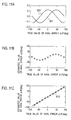
- FIGS. 11A to 11C and FIGS. 12A to 12C show simulation results of the above-described axial error estimation methods.
- the horizontal axes of FIGS. 11A to 11C and FIGS. 12A to 12C represent true values of the axial error ⁇ (the unit is degree in electric angle).
- the vertical axes of FIG. 11A and FIG. 12A represent values of the direct current component (i h ⁇ i h d) DC or (i ch ⁇ i ch d) DC .
- the vertical axes of FIGS. 11B and 11C , and FIGS. 12B and 12C represent an estimated value of the axial error ⁇ (the unit is degree in electric angle).
- FIGS. 11A to 11C show simulation results at the time when the superposed voltage is a perfect circle rotation voltage.
- the solid line 601 of FIG. 11A signifies an axial error ⁇ dependence property of (i h ⁇ i h d) DC
- the solid line 602 of FIG. 11A signifies an axial error ⁇ dependence property of (i ch ⁇ i ch d) DC
- the group of white circles in FIG. 11B show the estimated values of the axial error ⁇ that are computed based on the above equation (B-5) using the approximations of “sin(2 ⁇ ) ⁇ 2 ⁇ ” and “sin(4 ⁇ ) ⁇ 4 ⁇ ”.
- FIG. 11C show the estimated values of the axial error ⁇ computed based on the above equations (B-12), (B-13), (B-14), or (B-17).
- the solid line 610 of FIG. 11C is a line drawn along the group of white circles of FIG. 11C .
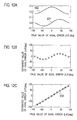
- FIGS. 12A to 12C show simulation results at the time when the superposed voltage is an alternating voltage.
- the solid line 621 of FIG. 12A signifies an axial error ⁇ dependence property of (i h ⁇ i h d) DC
- the solid line 622 of FIG. 12A signifies an axial error ⁇ dependence property of (i ch ⁇ i ch d) DC
- the group of white circles in FIG. 12B show the estimated values of the axial error ⁇ that are computed based on the above equation (B-5) using the approximations of “sin(2 ⁇ ) ⁇ 2 ⁇ ” and “sin(4 ⁇ ) ⁇ 4 ⁇ ”.
- FIG. 12C show the estimated values of the axial error ⁇ computed based on the above equations (B-12), (B-13), (B-14), or (B-17).
- the solid line 630 of FIG. 12C is a line drawn along the group of white circles of FIG. 12C .
- the estimation method of the magnetic pole position (axial error) based on the first to the fourth axis components of the superposed current as described above will be called an “estimation method based on four axis current components” for convenience below.
- the first, second, third, and fourth axes are either the ⁇ -axis, the d-axis, the ⁇ ′-axis, and the d′-axis, or the a-axis, the ⁇ -axis, the a′-axis, and the ⁇ ′-axis.
- the estimation method of the magnetic pole position (axial error) using the above-described equations (B-12), (B-13), (B-14), (B-17), (C-6), (C-7), (C-8), or (C-11) belongs to the estimation method based on four axis current components.
- the superposed voltage actually added to the drive voltage can be any of the perfect circle rotation voltage, the ellipsoidal rotation voltage, and the alternating voltage as described above.
- information for (i ch ⁇ i ch d) DC includes the offset component by the coefficient K 0 , and since this offset component affects the estimation accuracy, it is necessary to provide an accurate offset component value to the motor control device 3 beforehand.
- the perfect circle rotation voltage is adopted, the coefficient K 0 is zero, and thus, there is no need to find out the accurate offset component value.
- the value for the coefficient K 0 may be found out such as through experiments or simulations and may be provided to the motor control device 3 beforehand. If an alternating voltage in the d-axis direction (an alternating voltage having only the d-axis component) is used as the superposed voltage, it becomes unnecessary to apply a current that involves in the torque (the q-axis current) in order to estimate the magnetic pole position, and thus, torque fluctuation derived from the applied superposed voltage can be suppressed.
- the ellipsoidal rotation voltage is utilized as the superposed voltage, if the major axis direction of the ellipse is made to coincide with the d-axis direction, a current involved in the torque (the q-axis current) can be made small, and thus torque fluctuation derived from the applied superposed voltage can be suppressed.
- a method that detects current values of the current that flows between an inverter 2 and a direct current power source (not shown) that supplies power to the inverter 2 using a current sensor and that derives current values of three-phase currents (i u , i v , and i w ) based on the detected current values (hereinafter referred to as a one-shunt current detection method) See for example Japanese Patent Laid-Open No. 2008-099542.
- the one-shunt current detection method it is also known that three-phase currents cannot be detected when the voltage level difference between the maximum phase and the intermediate phase of the voltage and the voltage level difference between the minimum phase and the intermediate phase of the voltage among the phase voltages v u , v v , and v w become too close, and in order to avoid it, a correction with respect to each phase voltage is necessary.
- a voltage correction is performed, the superposed voltage for magnetic pole position estimation becomes different from an intended superposed voltage, and if the superposed voltage is the alternating voltage, the influence of the voltage correction becomes large.
- the ellipsoidal rotation voltage is utilized as the superposed voltage, there is an advantage that the influence of the voltage correction is small.
- ⁇ ′-axis and the d′-axis were defined as axes advanced by p/4 in electric angle from the ⁇ -axis and the d-axis respectively, it is also possible to carry out the above-described operations and the operations in each of the embodiments as described below upon defining that the ⁇ ′-axis and the d′-axis are axes advanced by ⁇ x in electric angle from the ⁇ -axis and the d-axis respectively.
- ⁇ x is an angle other than p/4 and other than zero (therefore, the ⁇ ′-axis differs from the ⁇ -axis and the d-axis, and the d′-axis differs from the ⁇ -axis and the d-axis).
- the ⁇ ′-axis and the d′-axis are defined as axes with their phases advanced by ⁇ x in electric angle from the ⁇ -axis and the d-axis respectively, there is an instance in which the coefficient K 0 does not become zero. In that case, the value for the coefficient K 0 may be found out beforehand such as through experiments or simulations and may be provided to the motor control device 3 .
- FIG. 13 is a block diagram of a motor drive system according to the first embodiment.
- the motor drive system of FIG. 13 includes the motor 1 and the inverter 2 of FIG. 1 , as well as a motor control device 3 a and a phase current sensor 11 .
- the motor control device 3 a may be utilized as the motor control device 3 of FIG. 1 .
- the motor control device 3 a includes each unit referred to by reference numbers 12 to 23 . It also may be considered that the phase current sensor 11 is included in the motor control device 3 a .
- Each unit within the motor control device 3 a can freely utilize each value generated within the motor control device 3 a.
- Each unit that constitutes the motor drive system of this embodiment and each of the embodiments described below updates command values (such as v ⁇ *, vd*, i ⁇ *, id*) and state quantities (such as i u , i v , i ⁇ , id, ⁇ and ⁇ ) that it computes (or detects) and outputs at a predetermined updating cycle, and carries out necessary operations utilizing the updated values.
- command values such as v ⁇ *, vd*, i ⁇ *, id*
- state quantities such as i u , i v , i ⁇ , id, ⁇ and ⁇
- the motor control device 3 a performs a vector control of the motor 1 such that the axial error ⁇ converges to zero. Therefore, in the first embodiment, the ⁇ -axis, which is an estimated axis for control, is made to coincide with the d-axis corresponding to the magnetic pole position (in other words, the dq-axes are estimated).
- the position/speed estimator 20 computes the phase ⁇ as the estimated magnetic pole position (that is, estimates the magnetic pole position), and also computes the rotation speed ⁇ (that is, estimates the rotation speed of the motor 1 ). Methods for these computations will be described below.
- the phase current sensor 11 detects a U-phase current value i u and a V-phase current value i v that are fixed axis components of the motor current I a supplied from the inverter 2 to the motor 1 .
- the coordinate converter 12 computes a ⁇ -axis current value i ⁇ and a d-axis current value id by coordinate converting the U-phase current value i u and the V-phase current value i v to the current values on the ⁇ -axes based on the phase ⁇ from the position/speed estimator 20 .
- the subtractor 19 refers to the rotation speed ⁇ from the position/speed estimator 20 and a rotation speed command value ⁇ * from a rotation speed command value generation unit (not shown) provided either externally or internally to the motor control device 3 a , and computes the velocity deviation ( ⁇ * ⁇ ) between them.
- the speed control unit 17 computes and outputs the d-axis current command value id* such that the velocity deviation ( ⁇ * ⁇ ) converges to zero by utilizing a control such as a proportional-integral control.
- the magnetic flux control unit 16 determines the ⁇ -axis current command value i ⁇ *.
- the subtractor 13 subtracts the ⁇ -axis current value i ⁇ outputted from the coordinate converter 12 from the ⁇ -axis current command value i ⁇ * outputted by the magnetic flux control unit 16 , and computes a current error (i ⁇ * ⁇ i ⁇ ).
- the subtractor 14 subtracts the d-axis current value id outputted by the coordinate converter 12 from the d-axis current command value id* outputted from the speed control unit 17 , and computes a current error (id* ⁇ id).
- the current control unit 15 performs a current feedback control utilizing for example a proportional-integral control such that the current errors (i ⁇ * ⁇ i ⁇ ) and (id* ⁇ id) both converge to zero.
- the ⁇ -axis voltage command value v ⁇ * and the d-axis voltage command value vd* are computed such that the current errors (i ⁇ * ⁇ i ⁇ ) and (id* ⁇ id) both converge to zero by utilizing a non-interacting control to eliminate interaction between the ⁇ -axis and the d-axis.
- ⁇ , i ⁇ , and id also are referred to when computing v ⁇ * and vd*.
- the high frequency voltage applying unit 21 generates the command values v h ⁇ * and v h d* for applying a high frequency superposed voltage to the motor 1 .
- v h ⁇ * and v h d* generated at the high frequency voltage applying unit 21 are defined by the above equation (A-1).
- the superposed voltage to be applied by the high frequency voltage applying unit 21 may be a perfect circle or ellipsoidal rotation voltage or an alternating voltage, as described above.
- v h ⁇ * and v h d* from the high frequency voltage applying unit 21 are added to v ⁇ * and vd* from the current control unit 15 , and the added values (v ⁇ *+v h ⁇ *) and (vd*+v h d*) are obtained.
- (v ⁇ *+v h ⁇ *) and (vd*+v h d*) respectively represent the ⁇ -axis component and the d-axis component of the voltage in which the superposed voltage is added to the drive voltage.
- the coordinate converter 18 computes and outputs three-phase voltage command values by coordinate converting the output values (v ⁇ *+v h ⁇ *) and (vd*+v h d*) of the adders 22 and 23 onto the three-phase fixed coordinate axes based on the phase ⁇ from the position/speed estimator 20 .
- the three-phase voltage command values are composed of the U-phase, V-phase, and W-phase voltage command values v u *, v v *, and v w * that specify the U-phase, V-phase, and W-phase voltage values v u , v v , and v w .
- the inverter 2 drives the motor 1 by supplying the motor current I a according to the three-phase voltage command values such that the actual U-phase, V-phase, and W-phase voltage values v u , v v , and v w coincide with the U-phase, V-phase, and W-phase voltage command values v u *, v v *, and v w * respectively.
- FIG. 14 shows a block diagram of an estimation processing unit 50 that is part of the position/speed estimator 20 .
- the estimation processing unit 50 includes each unit referred to by reference numbers 51 to 60 , and computes the axial error ⁇ and the phase ⁇ (that is, estimates the magnetic pole position) according to the “estimation method based on four axis current components”.
- the BPF (bandpass filter) 51 receives the ⁇ -axis current value i ⁇ outputted successively by the coordinate converter 12 , and extracts the ⁇ -axis component of the superposed current i h ⁇ by extracting a frequency ⁇ h signal component of the superposed voltage from the signal having i ⁇ as its signal value.
- the BPF 52 receives the d-axis current value id outputted successively by the coordinate converter 12 , and extracts the d-axis component of the superposed current i h d by extracting a frequency ⁇ h signal component of the superposed voltage from the signal having id as its signal value.
- the multiplier 53 computes a product of i h ⁇ and i h d extracted by the BPF 51 and 52 , i.e. (i h ⁇ i h d).
- the LPF (Low Pass Filter) 54 extracts and outputs the direct current component of the product (i h ⁇ i h d), i.e. (i h ⁇ i h d) DC , by removing the high frequency component from this product (i h ⁇ i h d).
- the high frequency component removed by the LPF 54 is a frequency component including the frequency ⁇ h other than the direct current component. The same thing applies to the high frequency components removed by the LPF 56 and the LPF 74 and 76 (see FIG. 17 ), which will be described below.
- the operation unit 55 is a unit that computes the product (i ch ⁇ i ch d).
- FIG. 14 shows that within the operation unit 55 a sum and a difference of i h ⁇ and i h d are obtained and then a product of the sum and the difference (i h ⁇ +i h d) ⁇ (i h ⁇ i h d) is obtained.
- the LPF 56 extracts and outputs the direct current component of the product (i h ⁇ +i h d) ⁇ (i h ⁇ i h d), i.e.
- (i h ⁇ 2 ⁇ i h d 2 ) may be computed instead at the operation unit 55 based on the output values i h ⁇ and i h d of the BPF 51 and 52 .
- the LPF 56 extracts and outputs the direct current component of (i h ⁇ 2 ⁇ i h d 2 ), i.e. (i h ⁇ 2 ⁇ i h d 2 ) DC , by removing the high frequency component from (i h ⁇ 2 ⁇ i h d 2 ).
- the product of the orthogonal two-axes components (i ch ⁇ i ch d) regarding the ⁇ ′-axis and the d′-axis is computed by computing the product (i h ⁇ +i h d) ⁇ (i h ⁇ i h d) or the value (i h ⁇ 2 ⁇ i h d 2 ) (to be exact, 2 (i ch ⁇ i ch d) is computed).
- the subtractor 57 subtracts the coefficient K from the output value of the LPF 56 and outputs its subtraction result to the operation unit 58 .
- the coefficient K is double the above coefficient K 0 .
- the coefficient K 0 becomes zero as described above, and thus the subtraction process by the subtractor 57 is unnecessary.
- the operation unit 58 computes the axial error ⁇ according to the above equations (B-12) to (B-14) or computes the axial error ⁇ according to the above equations (B-15) to (B-17) based on the output value of the LPF 54 (i h ⁇ i h d) DC and the output value of the subtractor 57 which corresponds to 2 ⁇ ((i ch ⁇ i ch d) DC ⁇ K 0 ).
- the proportional-integral (PI) control unit 59 performs a proportional-integral control so as to achieve a PLL (Phase Locked Loop) control and computes the rotation speed my such that the axial error ⁇ outputted by the operation unit 58 converges to zero.
- PLL Phase Locked Loop
- the integrator 60 computes the phase ⁇ by integrating the rotation speed ⁇ outputted by the proportional-integral control unit 59 .
- ⁇ and ⁇ computed here are given to each unit of the motor control device 3 a that requires these values as the output values of the position/speed estimator 20 .
- the ⁇ -axis follows the d-axis as an estimated axis of the d-axis.
- the magnetic pole position in the range of ⁇ p/2 to p/2 is estimated by the computation of ⁇ at the estimation processing unit 50 of FIG. 14 , but if the magnetic pole position in the range of ⁇ p top needs to be estimated, it is only necessary to provide a polar character determination unit (not shown) separately.
- the polar character determination unit for example determines whether or not to add p to the output value of the integrator 60 by utilizing current information from the detection result of the phase current sensor 11 or utilizing at least one Hall sensor, and only when it is necessary, adds p to the output value of the integrator 60 and outputs the addition result as the eventual phase ⁇ from the position/speed estimator 20 .
- FIG. 15A shows a simulation result concerning convergence of the axial error ⁇ utilizing the motor drive system of the first embodiment.
- FIG. 15B is a reference simulation result to be compared with FIG. 15A .
- the horizontal axes represent time (the unit is second), and the vertical axes represent the axial error ⁇ (the unit is degree in electric angle).
- the curved lines 651 and 652 of FIG. 15A both represent time variations of the axial error ⁇ computed by the estimation processing unit 50 .
- the curved lines 651 a and 652 a of FIG. 15B represent time variations of the axial error ⁇ computed by a reference estimation method.
- the axial error ⁇ was estimated by substituting (i h ⁇ i h d) DC in the equation obtained by substituting the approximations “sin(2 ⁇ ) ⁇ 2 ⁇ ” and “sin(4 ⁇ ) ⁇ 4 ⁇ ” in the above equation (B-5).
- the initial axial error ⁇ was set to be 30°
- the initial axial error ⁇ was set to be 90°.
- the “estimation method based on four axis current components” of the present invention even in a case where the initial axial error ⁇ is relatively large, the axial error ⁇ converges to zero in a short time (that is, it becomes possible to estimate the magnetic pole position ⁇ in a short time). Also, as will be explained in another embodiment (including the fourth embodiment) described below, it is possible to treat the magnetic pole position estimated by the “estimation method based on four axis current components” as the initial magnetic pole position, and subsequently estimate the magnetic pole position without utilizing application of the high frequency superposed voltage while being based on that initial magnetic pole position.
- the estimation of the initial magnetic pole position can be completed in a short time, it becomes possible to shorten the time during which the high frequency superposed voltage is applied. As a result, it becomes possible to shorten the time period of an occurrence of noise originating from the application of the high frequency superposed voltage.
- the estimation of the magnetic pole position without utilizing application of the high frequency superposed voltage is performed based on i ⁇ , id, v ⁇ *, and vd* for example.
- v ⁇ * and vd* are not inputted to the estimation processing unit 50 of FIG. 14 , considering that the estimation of the magnetic pole position without utilizing application of the high frequency superposed voltage at the position/speed estimator 20 , the aspect that i ⁇ , id, v ⁇ *, and vd* are entered to the position/speed estimator 20 is shown in FIG. 13 (the same thing applies to such as FIG. 16 which will be described below).
- FIG. 16 is an internal block diagram of a motor drive system according to the second embodiment.
- the motor drive system of FIG. 16 includes the motor 1 and the inverter 2 of FIG. 1 , as well as a motor control device 3 b and the phase current sensor 11 .
- the motor control device 3 b may be utilized as the motor control device 3 of FIG. 1 .
- the motor control device 3 b includes each unit referred to by reference numbers 12 b , 13 to 17 , 18 b , 19 , 20 b , and 21 b . It also may be considered that the phase current sensor 11 is included in the motor control device 3 b .
- Each unit within the motor control device 3 b can utilize freely each value generated within the motor control device 3 b.
- the motor control device 3 b performs a vector control of the motor 1 such that the axial error ⁇ converges to zero. Therefore, in the second embodiment, the ⁇ -axis, which is an estimated axis for control, is made to coincide with the d-axis corresponding to the magnetic pole position (in other words, the dq-axes are estimated).
- the position/speed estimator 20 b computes the phase ⁇ as the estimated magnetic pole position (that is, estimates the magnetic pole position), and also computes the rotation speed ⁇ (that is, estimates the rotation speed of the motor 1 ). Methods for these computations will be described below.
- the coordinate converter 12 b computes the a-axis current value ia and the ⁇ -axis current value i ⁇ by coordinate conversion of the U-phase current value i u and the V-phase current value i v to the current values on the a ⁇ -axes, and computes the ⁇ -axis current value i ⁇ and the d-axis current value id by coordinate conversion of the current value ia and the current value i ⁇ (or i u and i v ) to the current values on the ⁇ -axes based on the phase ⁇ from the position/speed estimator 20 b.
- the high frequency voltage applying unit 21 b generates the command values v h a* and v h ⁇ * for applying a high frequency superposed voltage to the motor 1 .
- v h a* and v h ⁇ * generated at the high frequency voltage applying unit 21 b are defined by the above equation (C-1).
- the superposed voltage to be applied by the high frequency voltage applying unit 21 b may be a perfect circle or ellipsoidal rotation voltage or an alternating voltage, as described above.
- the coordinate converter 18 b computes and outputs three-phase voltage command values (v u *, v v *, and v w *) by coordinate converting v ⁇ *, vd*, v h a*, and v h ⁇ * onto the three-phase fixed coordinate axes based on v ⁇ * and vd* from the current control unit 15 , v h a* and v h ⁇ * from the high frequency voltage applying unit 21 b , and the phase ⁇ from the position/speed estimator 20 b .
- the inverter 2 drives the motor 1 by supplying the motor current I a according to the three-phase voltage command values such that the actual U-phase, V-phase, and W-phase voltage values v u , v v , and v w coincide with the U-phase, V-phase, and W-phase voltage command values v u *, v v *, and v w * respectively.
- FIG. 17 shows a block diagram of an estimation processing unit 70 in the position/speed estimator 20 b .
- the estimation processing unit 70 includes each unit referred to by reference numbers 71 to 81 , and computes the phase ⁇ (that is, estimates the magnetic pole position) according to the “estimation method based on four axis current components”.
- Functions of the units referred to by the reference numbers 71 - 77 , 79 and 80 are the same as the functions of the units referred to by the numbers 51 to 57 , 59 , and 60 of FIG. 14 .
- the estimation processing unit 50 of FIG. 14 carries out an operation based on current information on the ⁇ -axes
- the estimation processing unit 70 of FIG. 17 carries out an operation based on current information on the a ⁇ -axes.
- the BPF 71 receives the a-axis current value ia outputted successively by the coordinate converter 12 b , and extracts the a-axis component of the superposed current i h a by extracting a frequency ⁇ h signal component of the superposed voltage from the signal having ia as its signal value.
- the BPF 72 receives the ⁇ -axis current value i ⁇ outputted successively by the coordinate converter 12 b , and extracts the ⁇ -axis component of the superposed current i h ⁇ by extracting a frequency ⁇ h signal component of the superposed voltage from the signal having i ⁇ as its signal value.
- the multiplier 73 computes a product of i h a and i h ⁇ extracted by the BPF 71 and 72 , i.e. (i h a ⁇ i h ⁇ ).
- the LPF 74 extracts and outputs the direct current component of the product (i h a ⁇ i h ⁇ ), i.e. (i h a ⁇ i h ⁇ ) DC , by removing the high frequency component from this product (i h a ⁇ i h ⁇ ).
- the operation unit 75 is a unit that computes the product (i ch a ⁇ i ch ⁇ ).
- FIG. 17 shows the aspect that within the operation unit 75 a sum and a difference of i h a and i h ⁇ are obtained and then a product of the sum and the difference (i h a+i h ⁇ ) ⁇ (i h a ⁇ i h ⁇ ) is obtained.
- the LPF 76 extracts and outputs the direct current component of the product (i h a+i h ⁇ ) ⁇ (i h a ⁇ i h ⁇ ), i.e.
- (i h a 2 ⁇ i h ⁇ 2 ) may be computed instead at the operation unit 55 based on the output values i h a and i h ⁇ of the BPF 71 and 72 .
- the LPF 76 extracts and outputs the direct current component of (i h a 2 ⁇ i h ⁇ 2 ), i.e. (i h a 2 ⁇ i h ⁇ 2 ) DC , by removing the high frequency component from (i h a 2 ⁇ i h ⁇ 2 ).
- the product of the orthogonal two-axes components (i ch a ⁇ i ch ⁇ ) regarding the a′-axis and the ⁇ ′-axis is computed by computing the product (i h a+i h ⁇ ) ⁇ (i h a ⁇ i h ⁇ ) or the value (i h a 2 ⁇ i h ⁇ 2 ) (to be exact, 2(i ch a ⁇ i ch ⁇ ) is computed).
- the subtractor 77 subtracts the coefficient K from the output value of the LPF 76 and outputs its subtraction result to the operation unit 78 .
- the coefficient K is double the above coefficient K 0 .
- the coefficient K 0 becomes zero as described above, and thus the subtraction process by the subtractor 77 is unnecessary.
- the operation unit 78 computes the phase ⁇ d according to the above equations (C-6) to (C-8) or computes the phase ⁇ d according to the above equations (C-9) to (C-11) based on the output value of the LPF 74 (i h a ⁇ i h ⁇ ) DC and the output value of the subtractor 77 which corresponds to 2 ⁇ ((i ch a ⁇ i ch ⁇ ) DC ⁇ K 0 ).
- the subtractor 81 computes the axial error ⁇ by subtracting the phase ⁇ outputted by the integrator 80 from the phase ⁇ d computed at the operation unit 78 .
- the proportional-integral control unit 79 performs a proportional-integral control so as to achieve a PLL control and computes the rotation speed ⁇ such that the axial error ⁇ outputted by the subtractor 81 converges to zero.
- the integrator 80 computes the phase ⁇ by integrating the rotation speed ⁇ outputted by the proportional-integral control unit 79 .
- ⁇ and ⁇ computed here are given to each unit of the motor control device 3 b that requires these values as the output values of the position/speed estimator 20 b.
- the ⁇ -axis follows the d-axis as an estimated axis of the d-axis.
- the magnetic pole position in the range of ⁇ p/2 to p/2 is estimated by the computation of ⁇ at the estimation processing unit 70 of FIG. 17 , but if the magnetic pole position in the range of ⁇ p to p needs to be estimated, it is only necessary to provide a polar character determination unit (not shown) separately.
- the polar character determination unit for example determines whether or not to add p to the output value of the integrator 80 by utilizing current information from the detection result of the phase current sensor 11 or utilizing at least one Hall sensor, and only when it is necessary, adds p to the output value of the integrator 80 and outputs the addition result as the eventual phase ⁇ from the position/speed estimator 20 b.
- Effects similar to the first embodiment can be achieved by forming the motor drive system as described in the second embodiment.
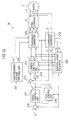
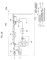
- FIG. 18 is a block diagram of a motor drive system according to the third embodiment.
- the motor drive system of FIG. 18 includes the motor 1 and the inverter 2 of FIG. 1 , as well as a motor control device 3 c and the phase current sensor 11 .
- the motor control device 3 c may be utilized as the motor control device 3 of FIG. 1 .
- the motor control device 3 c includes each unit referred to by reference numbers 112 to 121 . It also may be considered that the phase current sensor 11 is included in the motor control device 3 c .
- Each unit within the motor control device 3 c can utilize freely each value generated within the motor control device 3 c.
- the motor control device 3 c estimates the magnetic pole position directly without making the axial error ⁇ converge to zero.
- the position/speed estimator 120 computes the phase ⁇ d representing the magnetic pole position (that is, estimates the magnetic pole position), and also computes the rotation speed ⁇ d (that is, estimates the rotation speed of the motor 1 ). Methods for these computations will be described below.
- the coordinate converter 112 computes the a-axis current value ia and the ⁇ -axis current value i ⁇ by coordinate conversion of the U-phase current value i u and the V-phase current value i v to the current values on the a ⁇ -axes, and computes the dc-axis current value i dc and the qc-axis current value i qc by coordinate conversion of the current value ia and the current value i ⁇ (or i u and i v ) to the current values on the dcqc-axes based on the phase ⁇ d from the position/speed estimator 120 .
- the dc-axis and the qc-axis are estimated axes for the d-axis and q-axis, and if the phase ⁇ d computed by the position/speed estimator 120 coincides with the true phase ⁇ d , the dc-axis and the qc-axis coincide with the d-axis and the q-axis respectively, as shown in FIG. 19 .
- the dc-axis and the qc-axis will be called dcqc-axes collectively.
- a current vector control is performed on the dcqc-axes.
- the dc-axis component and the qc-axis component of the motor voltage V a will be called a dc-axis voltage and a qc-axis voltage respectively, and will be represented by the symbols v dc and v qc .
- the dc-axis component and the qc-axis component of the motor current I a will be called a dc-axis current and a qc-axis current respectively, and will be represented by the symbols i dc and i qc .
- Target values for the dc-axis voltage v dc and the qc-axis voltage v qc that the dc-axis voltage v dc and the qc-axis voltage v q are to follow are represented by a dc-axis voltage command value v dc * and a qc-axis voltage command value v qc * respectively.
- Target values for the dc-axis current i dc and the qc-axis current i qc that the dc-axis current i dc and the qc-axis current i q are to follow are represented by a dc-axis current command value i dc * and a qc-axis current command value i qc * respectively.
- the subtractor 119 refers to the rotation speed ⁇ d from the position/speed estimator 120 and the rotation speed command value ⁇ * from a rotation speed command value generation unit (not shown) provided either externally or internally to the motor control device 3 c , and computes the velocity deviation ( ⁇ * ⁇ d ) between them.
- the speed control unit 117 computes the qc-axis current command value i qc * such that the velocity deviation ( ⁇ * ⁇ d ) converges to zero by utilizing such as a proportional-integral control and outputs it.
- the magnetic flux control unit 116 determines the dc-axis current command value i dc *.
- a determination method of i dc * by the magnetic flux control unit 116 is the same as the determination method of i ⁇ * by the magnetic flux control unit 16 .
- the current control unit 115 performs a current feedback control utilizing for example a proportional-integral control such that the current errors (i dc * ⁇ i dc ) and (i qc * ⁇ i qc ) computed by the subtractors 113 and 114 both converge to zero.
- the dc-axis voltage command value v dc * and the qc-axis voltage command value v qc * are computed such that the current errors (i dc * ⁇ i dc ) and (i qc * ⁇ i qc ) both converge to zero by utilizing a non-interacting control to eliminate interaction between the dc-axis and the qc-axis.
- ⁇ d , i dc , and i qc also are referred to when computing v dc * and v qc *.
- the high frequency voltage applying unit 121 generates the command values v h a* and v h ⁇ * for applying a high frequency superposed voltage to the motor 1 .
- v h a* and v h ⁇ * generated at the high frequency voltage applying unit 121 are defined by the above equation (C-1).
- the superposed voltage to be applied by the high frequency voltage applying unit 121 may be a perfect circle or ellipsoidal rotation voltage or an alternating voltage, as described above.
- the coordinate converter 118 computes and outputs three-phase voltage command values (v u *, v v *, and v w *) by coordinate converting the command values v dc *, v qc *, v h a*, and v h ⁇ * onto the three-phase fixed coordinate axes based on the phase ⁇ d from the position/speed estimator 120 , v dc * and v qc * from the current control unit 115 , and v h a* and v h ⁇ * from the high frequency voltage applying unit 121 .
- the command values va* and v ⁇ * on the a ⁇ -axes that are target values of the a-axis voltage va and the ⁇ -axis voltage v ⁇ are computed by coordinate converting the command values v dc * and v qc * on the dcqc-axes onto the a ⁇ -axes based on the phase ⁇ d , and then added values (va*+v h a*) and (v ⁇ *+v h ⁇ *) are obtained by adding the command values v h a* and v h ⁇ * of the superposed voltage to the computed command values va* and v ⁇ *.
- the inverter 2 drives the motor 1 by supplying the motor current I a according to the three-phase voltage command values such that the actual U-phase, V-phase, and W-phase voltage values v u , v v , and v w coincide with the U-phase, V-phase, and W-phase voltage command values v u *, v v *, and v w * respectively.
- FIG. 20 shows a block diagram of an estimation processing unit 170 as part of the position/speed estimator 120 .
- the estimation processing unit 170 includes each unit referred to by reference numbers 71 to 78 , and computes the magnetic pole position ⁇ d (that is, estimates the magnetic pole position) according to the “estimation method based on four axis current components”. Functions of the units referred to by the reference numbers 71 - 78 are the same as those shown in FIG. 17 .
- a computed value of the phase ⁇ d is outputted from the operation unit 78 by the units referred to by the reference numbers 71 - 78 based on the current values ia and i ⁇ from the coordinate converter 112 .
- the rotation speed ⁇ d is computed by differentiating the phase ⁇ d , and the computed ⁇ d and ⁇ d are given to each unit of the motor control device 3 c that requires the value as output values of the position/speed estimator 120 .
- FIGS. 21A and 21B show simulation results concerning magnetic pole position estimation.
- the horizontal axes represent a true value of the magnetic pole position ⁇ d (the unit is degree in electric angle)
- the vertical axes represent an estimated value of the magnetic pole position ⁇ d (the unit is degree in electric angle).
- the group of white circles in FIG. 21B show magnetic pole positions ⁇ d estimated by the estimation processing unit 170 upon treating a true value of the magnetic pole position ⁇ d as a variable number.
- the solid line 680 of FIG. 21B is a line drawn along the group of white circles of FIG. 21B .
- FIG. 21A is a reference drawing for comparison with FIG. 21B .
- the estimated values for the magnetic pole position coincide with true values with high accuracy in the range of ⁇ p/2 to p/2 according to the estimation processing unit 170 , and thus, the estimated values can be utilized directly as magnetic pole position information.
- a magnetic polar character determination unit (not shown) is provided within the position/speed estimator 120 .
- the polar character determination unit for example determines whether or not to add p to the output value of the operation unit 78 by utilizing current information from the detection result of the phase current sensor 11 or utilizing at least one Hall sensor, and only when it is necessary, adds p to the output value of the operation unit 78 and outputs the addition result as the eventual phase ⁇ d from the position/speed estimator 120 .
- Effects similar to the first embodiment can be achieved by forming the motor drive system as described in the third embodiment. Also, by estimating the magnetic pole position directly without involving the PLL control (proportional-integral control) as in the motor drive system of the third embodiment, it becomes possible to estimate the magnetic pole position distinctly in a short time.
- PLL control proportional-integral control
- FIG. 22 is an operation flowchart of the motor drive system according to the fourth embodiment. During the time frame from the state in which rotation of the motor 1 is stopped and the magnetic pole position is unknown to the state of stable high-speed rotation of the motor 1 , processes of steps S 1 , S 2 , and S 3 are carried out sequentially.
- the initial magnetic pole position is estimated according to a first magnetic pole position estimation method.
- the initial magnetic pole position ⁇ d is estimated by the “estimation method based on four axis current components” without performing control such as a current control and a speed control.
- the motor 1 is vector controlled by estimating the magnetic pole position according to a second magnetic pole position estimation method based on an estimation result of the magnetic pole position ⁇ d by step S 1 .
- the second magnetic pole position estimation method may be the “estimation method based on four axis current components” or may be a different method.
- it may be a method described in Japanese Patent Laid-Open No. 2007-53829, that is, an estimation method of the magnetic pole position utilizing a ⁇ -axis component and a d-axis component of the superposed current.
- it is good to adopt a magnetic pole position estimation method with good estimation accuracy at the time of rotation stoppage or low-speed rotation of the motor 1 .
- step S 2 the process moves from step S 2 to step S 3 , and the estimation method of the magnetic pole position switches from the second magnetic pole position estimation method to the third magnetic pole position estimation method.
- the magnetic pole position is estimated by estimating an induced voltage in the motor 1 . Therefore, in the third magnetic pole position estimation method, application of the superposed voltage is unnecessary.
- the process of step S 2 may be omitted and the process may move directly to step S 3 after the initial magnetic pole position ⁇ d is estimated at step S 1 .
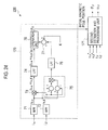
- FIG. 23 shows a specific structural example of the motor drive system that achieves the operations shown in FIG. 22 .
- FIG. 23 is an internal block diagram of a motor drive system according to the fourth embodiment.
- the motor drive system of FIG. 23 includes the motor 1 and the inverter 2 of FIG. 1 , as well as a motor control device 3 d and a phase current sensor 11 .
- the motor control device 3 d may be utilized as the motor control device 3 of FIG. 1 .
- the motor control device 3 d includes each unit referred to by reference numbers 212 to 221 . It also may be considered that the phase current sensor 11 is included in the motor control device 3 d .
- Each unit within the motor control device 3 d can utilize freely each value generated within the motor control device 3 a.
- the high frequency voltage applying unit 221 generates command values v h1 * and v h2 * for a superposed voltage. The meaning of these command values will become apparent by the explanations that are provided below.
- the motor control device 3 d When a command signal to start rotation of the motor 1 is inputted to the motor drive system of FIG. 23 , the motor control device 3 d carries out a process to estimate the initial magnetic pole position at step S 1 . That is, for example, it causes the position/speed estimator 220 to estimate and compute the phase ⁇ d by making the coordinate converters 212 , 218 , the position/speed estimator 220 , and the high frequency voltage applying unit 221 function as the coordinate converters 112 , 118 , the position/speed estimator 120 , and the high frequency voltage applying unit 121 of FIG. 18 .
- FIG. 24 shows a block diagram of the position/speed estimator 220 .
- the position/speed estimator 220 includes the estimation processing unit 170 and the second estimation processing unit 171 .
- the estimation processing unit 170 which is intrinsic in the position/speed estimator 220 is the same as that shown in FIG. 20 .
- the motor current I a according to these three-phase voltage command values are supplied from the inverter 2 to the motor 1 .
- the coordinate converter 212 computes the current values ia and i ⁇ by coordinate converting the current values i u and i v detected at the phase current sensor 11 at the time when the superposed voltage is applied to the current values on the a ⁇ -axes, and gives the computed current values ia and i ⁇ to the estimation processing unit 170 in the position/speed estimator 220 .
- the phase ⁇ d computed at the estimation processing unit 170 based on the computed current values ia and i ⁇ at step S 1 corresponds to the initial magnetic pole position to be estimated at step S 1 .
- steps S 1 operations of each unit referred to by the reference numbers 213 to 217 and 219 are stopped.
- the motor control device 3 d After the initial magnetic pole position is estimated at step S 1 , the motor control device 3 d starts the motor 1 by carrying out the process of step S 2 .
- the process makes the second estimation processing unit 171 to estimate the ⁇ -axis phase ⁇ and rotation speed ⁇ and makes each unit referred to by the reference numbers 212 to 219 within the motor control device 3 d to perform operations similar to that of each unit referred to by the reference numbers 12 to 19 of FIG. 13 .
- the second estimation processing unit 171 utilizes the initial magnetic pole position ⁇ d estimated by the estimation processing unit 170 at step S 1 as the phase ⁇ at the time of starting the process of step S 2 . Therefore, estimation of the magnetic pole position can be started from the state in which the axial error ⁇ is zero.
- the BPF 51 , the BPF 52 , the multiplier 53 , the LPF 54 , the proportional-integral control unit 59 , and the integrator 60 of FIG. 14 are provided as part of the second estimation processing unit 171 .
- step S 2 (i h ⁇ i h d) DC is computed utilizing the BPF 51 , the BPF 52 , the multiplier 53 , and the LPF 54 based on the ⁇ -axis current value i ⁇ and the d-axis current value id outputted by the coordinate converter 212 , and the axial error ⁇ is estimated by substituting (i h ⁇ i h d) DC in the equation obtained by substituting the approximations “sin(2 ⁇ ) ⁇ 2 ⁇ ” and “sin(4 ⁇ ) ⁇ 4 ⁇ ” in the above equation (B-5).
- step S 2 the rotation speed ⁇ and the phase ⁇ are computed through a proportional-integral control to converge this axial error ⁇ to zero by the proportional-integral control unit 59 and the integrator 60 .
- the motor 1 rotates at a desired rotation speed by performing a vector control to make the ⁇ -axis to follow the d-axis by supplying the rotation speed ⁇ computed at step S 2 (and S 3 ) to the current control unit 215 , the magnetic flux control unit 216 , and the subtractor 219 , and supplying the phase ⁇ computed at step S 2 (and S 3 ) to the coordinate converters 212 and 218 .
- the second estimation processing unit 171 computes the axial error ⁇ based on the current values i ⁇ and id from the coordinate converter 212 and command values v ⁇ * and vd* from the current control unit 215 , and computes the phase ⁇ and the rotation speed ⁇ by performing a proportional-integral control such that the axial error ⁇ converges to zero.
- the axial error ⁇ can be estimated by the following equation. Note that “s” in the following equation is the Laplace operator, and E ex ⁇ and E ex d are a ⁇ -axis component and a d-axis component of an extended induced voltage E ex respectively.
- p is the differential operator.
- step S 2 it is possible to omit the process of step S 2 .
- the process may move to step S 3 immediately after the initial magnetic pole position ⁇ d is estimated at step S 1 .
- the second estimation processing unit 171 utilizes the initial magnetic pole position ⁇ d estimated at step S 1 as the phase ⁇ at the time of starting the process of step S 3 .
- step S 1 the superposed voltage on the a ⁇ coordinate system is applied to the motor 1 , and the initial magnetic pole position is estimated based on the a-axis component and the ⁇ -axis component of the superposed voltage.
- direct estimation of the initial magnetic pole position is performed by focusing on the a ⁇ coordinate system in the process of step S 1 performed at the motor drive system of FIG. 23 .
- the coordinate system to be utilized when directly estimating the initial magnetic pole position may be a coordinate system other than the a ⁇ coordinate system.
- a direct estimation method of the initial magnetic pole position focusing on the ⁇ coordinate system will be explained.
- FIG. 25 is an internal block diagram of a motor drive system according to the fifth embodiment.
- the motor drive system of FIG. 25 includes the motor 1 and the inverter 2 of FIG. 1 , as well as a motor control device 3 e and a phase current sensor 11 .
- the motor control device 3 e may be utilized as the motor control device 3 of FIG. 1 .
- the motor control device 3 e includes each unit referred to by reference numbers 212 to 219 , 220 e , and 221 e . It also may be considered that the phase current sensor 11 is included in the motor control device 3 e .
- Each unit within the motor control device 3 e can utilize freely each value generated within the motor control device 3 e .
- the motor drive system of FIG. 25 also carries out the processes of steps S 1 , S 2 , and S 3 of FIG. 22 sequentially. However, it is also possible to omit the process of step S 2 .
- the motor control device 3 e When a command signal to start rotation of the motor 1 is inputted to the motor drive system of FIG. 25 , the motor control device 3 e carries out a process to estimate the initial magnetic pole position at step S 1 .
- the high frequency voltage applying unit 221 e applies the superposed voltage to motor 1 by generating command values v h ⁇ * and v h d* defined by the above equation (A-1).
- step S 1 it is not necessary that the ⁇ -axis coincide with the d-axis.
- the motor control device 3 e sets an arbitrary axis to be the ⁇ -axis.
- the phase ⁇ of the ⁇ -axis that is set at step S 1 is represented particularly by ⁇ 0 . Since the motor control device 3 e itself defines the ⁇ -axis, the phase ⁇ 0 is known by the motor control device 3 e .
- steps S 1 operations of each unit referred to by the reference numbers 213 to 217 and 219 are stopped. As such, since a PLL control is not performed during the process of step S 1 , the phase ⁇ of the ⁇ -axis remains stationary (that is, it is maintained in a constant value ⁇ 0 ).
- FIG. 26 shows a block diagram of the position/speed estimator 220 e .
- the position/speed estimator 220 e includes the estimation processing unit 170 e and the second estimation processing unit 171 e .
- the estimation processing unit 170 e includes each unit referred to by the reference numbers 51 to 58 , which are the same as that of FIG. 14 .
- step S 1 the following process is carried out at step S 1 by which the initial magnetic pole position is estimated.
- the coordinate converter 218 computes three-phase voltage command values by coordinate converting the command values v h ⁇ * and v h d* on the ⁇ -axes generated by the high frequency voltage applying unit 221 e onto the three-phase fixed coordinate axes based on the phase ⁇ 0 .
- the motor current I a according to these three-phase voltage command values are supplied from the inverter 2 to the motor 1 .
- the coordinate converter 212 computes the current values i ⁇ and id by coordinate converting the current values i u and i v detected at the phase current sensor 11 at the time when the superposed voltage is applied to the current values on the ⁇ -axes based on the phase ⁇ 0 , and gives the computed current values i ⁇ and id to the estimation processing unit 170 e .
- the axial error axial error ⁇ at step S 1 is computed from the operation unit 58 within the estimation processing unit 170 e . Addition of the phase ⁇ 0 to the axial error ⁇ computed at this step S 1 coincides with the phase ⁇ d at step S 1 (see FIG. 2A ). Therefore, the position/speed estimator 220 e estimates the addition the phase ⁇ 0 to the axial error ⁇ computed at this step S 1 as the initial magnetic pole position ⁇ d .
- the motor control device 3 e After the initial magnetic pole position is estimated at step S 1 , the motor control device 3 e starts the motor 1 by carrying out the process of step S 2 .
- the process makes the second estimation processing unit 171 e to estimate the ⁇ -axis phase ⁇ and rotation speed ⁇ and makes each unit referred to by the reference numbers 212 to 219 within the motor control device 3 e to perform operations similar to that of each unit referred to by the reference numbers 12 to 19 of FIG. 13 .
- the second estimation processing unit 171 e utilizes the initial magnetic pole position ⁇ d estimated at step S 1 as the phase ⁇ at the time of starting the process of step S 2 . Therefore, estimation of the magnetic pole position can be started from the state in which the axial error ⁇ is zero.
- the second estimation processing unit 171 e is similar to the second estimation processing unit 171 of FIG. 24 , and the estimation processes of the magnetic pole position at steps S 2 and S 3 are carried out according to the method shown in the fourth embodiment.
- Vector controls at steps S 2 and S 3 are performed based on these estimation results. As described above, the process of step S 2 may be omitted.
- the motor drive system as shown in FIG. 25 is equivalent to that of FIG. 23 .
- a vector control of the motor 1 is performed by estimating the magnetic pole position at steps S 2 and S 3 based on the initial magnetic pole position, after the initial magnetic pole position is estimated at the process of step S 1 .
- a synchronized operation V/f control
- application of the superposed voltage to the motor 1 is stopped.
- a control to converge the axial error ⁇ to zero is not performed, and the axial error ⁇ is widely variable according to for example the rotation speed command value ⁇ *.
- the rotation speed ⁇ of the motor 1 is made to coincide with the rotation speed command value ⁇ *.
- a current vector on the rotation coordinate system at the time of the synchronized operation is shown as a vector 590 in FIG. 27 .
- the current vector here is a vectorial representation of the motor current I a .
- the direction of the current vector is parallel to the d-axis and its amplitude is id 0 .
- the d-axis is delayed with respect to the q-axis so that torque generated by this current vector and the load torque are balanced out.
- an operation is performed in a state that the phase difference (axial error between the q-axis and the d-axis) is formed in which the load torque and the generated torque are balanced out.
- Such an operation is a synchronized operation.
- an estimation process using the estimation processing unit 50 of FIG. 14 or the estimation processing unit 70 of FIG. 17 (estimation process using the PLL control) may be utilized.
- the estimation process using the estimation processing unit 170 of FIG. 24 or the estimation processing unit 170 e of FIG. 26 (direct estimation process of the magnetic pole position without using the PLL control) is utilized instead, the time period of an occurrence of noise originated from the application of the high frequency superposed voltage is distinctly shortened.
- the motor 1 by starting the motor 1 according to the estimation of the magnetic pole position based on the induced voltage after the estimation of the initial magnetic pole position, it becomes possible to shorten the time period of an occurrence of noise originated from the application of the high frequency superposed voltage compared with a system that requires application of the high frequency superposed voltage even after the estimation of the initial magnetic pole position. If the estimation process using the estimation processing unit 170 of FIG. 24 or the estimation processing unit 170 e of FIG. 26 (direct estimation process of the magnetic pole position without using the PLL control) is utilized, the time period of an occurrence of noise originated from the application of the high frequency superposed voltage is distinctly shortened.
- the magnetic pole position estimation method based on the induced voltage is a kind of magnetic pole position estimation method for high-speed rotation that is suitable especially at the time of high-speed rotation.
- start of the motor fails depending on the initial magnetic pole position.
- reliable motor start can be realized by estimating the initial magnetic pole position and then upon consideration of the estimated result starting the motor.
- the motor 1 is for example an interior permanent magnet synchronous motor having a structural salient magnetic polar character.
- SPMSM surface permanent magnet synchronous motor
- the technical contents as described above may be applied to a surface permanent magnet synchronous motor (hereinafter referred to as “SPMSM”), which is a non-salient pole machine. That is, the SPMSM may be adopted as the motor 1 .
- the SPMSM motor 1 it is good to make the SPMSM motor 1 to have a salient magnetic polar character by producing magnetic saturation.
- the d-axis inductance L d decreases when the magnetic saturation occurs, the superposed current becomes susceptible to flow in the d-axis direction. That is, since the SPMSM behaves as if it has a salient magnetic polar character, an estimation process similar to the case in which the motor 1 is a salient pole machine becomes possible.
- the synchronous reluctance motor as the motor 1 includes a rotor and a stator having U, V, and W phase armature winding, but the rotor is not provided with a permanent magnet, and the rotor is rotated utilizing only the reluctance torque by a salient polar character of an iron core that forms the rotor (or an iron core that forms the rotor and the stator).
- a permanent magnet to the rotor of the synchronous reluctance motor as the motor 1 for creating field.
- the rotor is formed such that a direction in which a magnetic flux is susceptible to flow (a direction in which a magnetic resistance is relatively small) and a direction in which a magnetic flux is hard to flow (a direction in which a magnetic resistance is relatively large) exist in the rotor of the synchronous reluctance motor as the motor 1 .
- the axes along the former and the latter respectively correspond to the d-axis and the q-axis of the synchronous reluctance motor as the motor 1 .
- the d-axis and the q-axis at the synchronous reluctance motor are mutually orthogonal in a rotating coordinate system expressed in electric angle.
- the motor drive system of the invention as described above is applicable in various electrical equipment which operates by utilizing torque of a motor within the motor drive system.
- FIG. 28 is a block diagram of an electric vehicle 400 in which the motor drive system of the invention is mounted.
- Motors 401 a and 401 b , inverters 402 a and 402 b , a control device 403 , and batteries 402 a and 402 b composed of secondary batteries are mounted in the electric vehicle 400 , and the electric vehicle 400 runs by rotating the wheels of the electric vehicle 400 by utilizing the torque of the motors 401 a and 401 b.
- Each of the motors 401 a and 401 b is the same as the motor 1 , and each of the inverters 402 a and 402 b are the same as the inverter 2 .
- a motor control device for the motor 401 a and a motor control device for the motor 401 b are intrinsic in the control device 403 , and each motor control device within the control device 403 is the same as the motor control device 3 .
- the control device 403 generates three-phase voltage command values for the inverter 402 a based on the motor current I a that flows in the motor 401 a , and generates three-phase voltage command values for the inverter 402 b based on the motor current I a that flows in the motor 401 b.
- the inverter 402 a converts a direct current voltage outputted by the battery 404 a to three-phase alternate current voltages based on the three-phase voltage command values for the inverter 402 a , and drives the motor 401 a by applying the three-phase alternate current voltages to the motor 401 a .
- the inverter 402 b converts a direct current voltage outputted by the battery 404 b to three-phase alternate current voltages based on the three-phase voltage command values for the inverter 402 b , and drives the motor 401 b by applying the three-phase alternate current voltages to the motor 401 b.
- FIG. 29A is an outline view of an air conditioning machine 420 in which the motor drive system of the invention is mounted.
- the air conditioning machine 420 is a so-called outdoor machine of an air conditioner.
- the air conditioning machine 420 is provided with a compressor 421 , as well as a motor drive system composed of the motor 2 , the inverter 2 , and the motor control device 3 .
- the motor 1 and the inverter 2 (or just the motor 1 ) are built into the compressor 421 .
- FIG. 29B is an outline view of the compressor 421 .
- the air within a subject room is adjusted by the compressor 421 performing compression of the refrigerant gas (not shown) by using torque of the motor 1 as its driving source.
- the magnetic pole position estimation method of the invention not only sine function information but also cosine function information is utilized, and therefore, the estimated axis (the ⁇ -axis) and the axis corresponding to the magnetic pole position do not necessarily need to coincide, and a magnetic pole position can be estimated accurately in a short time even in a case that the axial error between these axes is relatively large.
- the initial magnetic pole position is estimated by the magnetic pole position estimation method of the invention, it is possible to shorten the time period of an occurrence of noise originated from the application of the high frequency superposed voltage by switching the magnetic pole position estimation method to one that does not require applying a high frequency superposed voltage.
- the phase current sensor 11 is used to detect the U-phase current value iu and the v-phase current value iv directly. However, they can be detected by the one-shunt current detection method which also was described above.
- a derivation method of all the values to be derived including the various command values (such as i ⁇ *, id*, v ⁇ *, and vd*) and state quantities (such as i ⁇ and id) as described above is arbitrary. For example, they may be derived by operations within the motor control device ( 3 , 3 a , 3 b , 3 c , 3 d , or 3 e ) or they may be derived from table data that are previously set.
- a part or all of the functions of the motor control device are achieved for example by using software (program) built in such as a general microcomputer.
- software program built in such as a general microcomputer.
- the block diagram showing the configuration of each unit of the motor control device indicates a functional block diagram.
Landscapes
- Engineering & Computer Science (AREA)
- Power Engineering (AREA)
- Control Of Ac Motors In General (AREA)
- Control Of Motors That Do Not Use Commutators (AREA)
Abstract
Description
(i hγ ×i hδ)DC =K 1 sin(2Δθ)+K 2 sin(4Δθ) (B-5)
(i chγ ×i chδ)DC =K 0 +K 1 cos(2Δθ)+K 2 cos(4Δθ) (B-9)
(i hγ ×i hδ)DC ≈K 1 sin(2Δθ) (B-10)
(i chγ ×i chδ)DC ≈K 1 cos(2Δθ)+K 0 (B-11)
Claims (11)
Applications Claiming Priority (2)
| Application Number | Priority Date | Filing Date | Title |
|---|---|---|---|
| JP2008-211893 | 2008-08-20 | ||
| JP2008211893A JP5324159B2 (en) | 2008-08-20 | 2008-08-20 | Motor control device |
Publications (2)
| Publication Number | Publication Date |
|---|---|
| US20100045218A1 US20100045218A1 (en) | 2010-02-25 |
| US8159161B2 true US8159161B2 (en) | 2012-04-17 |
Family
ID=41695732
Family Applications (1)
| Application Number | Title | Priority Date | Filing Date |
|---|---|---|---|
| US12/543,802 Active 2030-07-23 US8159161B2 (en) | 2008-08-20 | 2009-08-19 | Motor control device |
Country Status (2)
| Country | Link |
|---|---|
| US (1) | US8159161B2 (en) |
| JP (1) | JP5324159B2 (en) |
Cited By (20)
| Publication number | Priority date | Publication date | Assignee | Title |
|---|---|---|---|---|
| US20110031919A1 (en) * | 2009-08-10 | 2011-02-10 | Emerson Climate Technologies, Inc. | Controller and method for minimizing phase advance current |
| US20130069572A1 (en) * | 2011-09-15 | 2013-03-21 | Kabushiki Kaisha Toshiba | Motor control device |
| US20140292237A1 (en) * | 2013-03-29 | 2014-10-02 | Kabushiki Kaisha Yaskawa Denki | Motor control apparatus and magnetic-pole position estimating method |
| US20150042249A1 (en) * | 2013-08-08 | 2015-02-12 | Delta Electronics, Inc. | Estimating method for a rotor position of a motor and estimating device for the same |
| US8963459B2 (en) | 2011-09-07 | 2015-02-24 | Samsung Techwin Co., Ltd. | Method and apparatus for driving alternating-current motor |
| US20150091483A1 (en) * | 2012-02-28 | 2015-04-02 | Calsonic Kansei Corporation | Electric Motor Control Device |
| US20150115862A1 (en) * | 2012-07-09 | 2015-04-30 | Kabushiki Kaisha Yaskawa Denki | Motor control apparatus and motor system |
| US20150115850A1 (en) * | 2012-06-15 | 2015-04-30 | Danfoss Drives A/S | Variable torque angle for electric motor |
| US20150188472A1 (en) * | 2012-06-15 | 2015-07-02 | Danfoss Drives A/S | Method for controlling a synchronous reluctance electric motor |
| US9088232B2 (en) | 2009-08-10 | 2015-07-21 | Emerson Climate Technologies, Inc. | Power factor correction with variable bus voltage |
| EP2911293A2 (en) | 2014-02-24 | 2015-08-26 | Jenaer Antriebstechnik GmbH | Rotating field machine and method for determining the angular position of its rotor |
| US20150256117A1 (en) * | 2014-03-06 | 2015-09-10 | Kabushiki Kaisha Toshiba | Motor control device and air conditioner |
| US9154061B2 (en) | 2009-08-10 | 2015-10-06 | Emerson Climate Technologies, Inc. | Controller and method for transitioning between control angles |
| US9240749B2 (en) | 2012-08-10 | 2016-01-19 | Emerson Climate Technologies, Inc. | Motor drive control using pulse-width modulation pulse skipping |
| US20160126828A1 (en) * | 2013-06-26 | 2016-05-05 | Posco Energy Co., Ltd. | Apparatus and method for controlling overcurrent of grid-connected inverter due to abnormal grid voltage |
| US9634593B2 (en) | 2012-04-26 | 2017-04-25 | Emerson Climate Technologies, Inc. | System and method for permanent magnet motor control |
| US9948224B1 (en) * | 2016-10-17 | 2018-04-17 | General Electric Company | System and method for sensorless control of electric machines using magnetic alignment signatures |
| US20180123492A1 (en) * | 2016-10-28 | 2018-05-03 | Konica Minolta, Inc. | Controller for permanent magnet synchronous motor, control method, and image forming apparatus |
| US20190187598A1 (en) * | 2017-12-19 | 2019-06-20 | Canon Kabushiki Kaisha | Motor control apparatus, image forming apparatus, and method for controlling motor control apparatus |
| US11177759B2 (en) | 2018-11-28 | 2021-11-16 | General Electric Company | System and method for self-sensing of electric machines and reduction of noise and vibration associated therewith |
Families Citing this family (36)
| Publication number | Priority date | Publication date | Assignee | Title |
|---|---|---|---|---|
| JP4434184B2 (en) * | 2006-08-17 | 2010-03-17 | アイシン・エィ・ダブリュ株式会社 | Method and apparatus for feedback control of electric motor |
| JP2011200105A (en) * | 2010-02-26 | 2011-10-06 | Denso Corp | Controller for electric rotating machine |
| KR101657523B1 (en) * | 2011-09-07 | 2016-09-19 | 한화테크윈 주식회사 | Method and apparatus for driving alternating-current motor |
| FR2986389B1 (en) * | 2012-01-31 | 2014-03-14 | Hispano Suiza Sa | CONTROL OF AN ELECTRIC MACHINE WITH PERMANENT MAGNETS |
| KR101618490B1 (en) | 2012-02-22 | 2016-05-04 | 가부시키가이샤 야스카와덴키 | Magnetic pole position estimating apparatus for electric motor, controlling apparatus for electric motor, and magnetic pole position estimating method for electric motor |
| KR101995864B1 (en) * | 2012-07-25 | 2019-07-04 | 삼성전자주식회사 | Inverter control apparatus and method thereof |
| JP6089608B2 (en) * | 2012-11-08 | 2017-03-08 | 株式会社明電舎 | Control method of synchronous motor |
| ITVI20120331A1 (en) * | 2012-12-10 | 2014-06-11 | Reel Srl | METHOD FOR THE SYNCHRONIZATION OF A SYNCHRONOUS ELECTRIC REPLACEMENT MACHINE |
| WO2014128887A1 (en) * | 2013-02-21 | 2014-08-28 | 三菱電機株式会社 | Motor control device |
| US20140327379A1 (en) * | 2013-05-03 | 2014-11-06 | Texas Instruments Incorporated | Position sensorless drive system and method for permanent magnet motors |
| JP5709932B2 (en) * | 2013-05-17 | 2015-04-30 | 三菱電機株式会社 | Synchronous machine controller |
| KR101972873B1 (en) * | 2013-07-24 | 2019-04-30 | 현대일렉트릭앤에너지시스템(주) | Apparatus and mehtod of estimating porition of rotor in wound rotor synchronous motor |
| CN103684171A (en) * | 2013-11-26 | 2014-03-26 | 深圳市星辰激光技术有限公司 | Method and system for controlling speeds of alternating-current motors |
| CN103916065B (en) * | 2014-04-21 | 2016-02-03 | 西北工业大学 | A kind of electric excitation synchronous motor stationary rotor initial position evaluation method of position-sensor-free |
| CN103916066B (en) * | 2014-04-21 | 2016-02-03 | 西北工业大学 | The electric excitation synchronous motor stationary rotor initial position evaluation method of position-sensor-free |
| US9990333B1 (en) * | 2014-05-28 | 2018-06-05 | University Of South Florida | Systems and methods for synchronizing the kinematics of uncoupled, dissimilar rotational systems |
| DE102015211863A1 (en) | 2015-06-25 | 2016-12-29 | Lenze Automation Gmbh | Method for determining current-dependent and / or angular position-dependent characteristics of an electrical machine and frequency converter |
| JP6614825B2 (en) * | 2015-06-30 | 2019-12-04 | 日立ジョンソンコントロールズ空調株式会社 | Power conversion device, motor drive device, refrigeration device |
| JP6490540B2 (en) * | 2015-08-25 | 2019-03-27 | 株式会社東芝 | Rotation position detection device, air conditioner, and rotation position detection method |
| CN105262397B (en) * | 2015-10-29 | 2018-06-29 | 四川长虹电器股份有限公司 | A kind of variable-frequency motor location current control method |
| CN106911283B (en) * | 2015-12-23 | 2023-08-04 | 罗伯特·博世有限公司 | Method and device for online estimation of the initial position of a surface permanent magnet machine |
| CN105680747A (en) * | 2016-03-09 | 2016-06-15 | 上海贝思特控制技术有限公司 | Synchronous motor self-tuning method suitable for vertical elevator |
| CH712829A1 (en) * | 2016-08-22 | 2018-02-28 | Lakeview Innovation Ltd | Method for sensorless control of a PMSM motor. |
| TWI668953B (en) * | 2016-08-22 | 2019-08-11 | 日商東芝股份有限公司 | Inverter control device and drive system |
| CN107482984B (en) * | 2016-10-12 | 2019-09-20 | 宝沃汽车(中国)有限公司 | Motor initial position angle automatic Calibration angle compensation process and system |
| CN108063574A (en) * | 2016-11-09 | 2018-05-22 | 密克罗奇普技术公司 | Start the system and method for synchronous motor |
| JP6681554B2 (en) * | 2017-02-22 | 2020-04-15 | パナソニックIpマネジメント株式会社 | Motor drive for washing machine |
| WO2018179620A1 (en) * | 2017-03-27 | 2018-10-04 | 三菱電機株式会社 | Rotating electric machine control device |
| CN106849804A (en) * | 2017-04-17 | 2017-06-13 | 哈尔滨工业大学 | A kind of permanent-magnet synchronous motor rotor position observer of random frequency high frequency square wave voltage injection |
| CN109150052B (en) * | 2018-08-13 | 2020-04-24 | 哈尔滨工业大学 | High-frequency noise suppression method of random sine injection permanent magnet motor rotor position observer considering digital control delay |
| JP7077878B2 (en) * | 2018-08-31 | 2022-05-31 | 株式会社アドヴィックス | Motor control device |
| CN109458336B (en) * | 2018-12-13 | 2021-10-29 | 青岛海尔空调器有限总公司 | Method for controlling rotation speed of single-rotor compressor |
| CN109656304B (en) * | 2018-12-13 | 2021-02-12 | 成都芯源系统有限公司 | Current generating circuit and Hall circuit thereof |
| DE112019007350T5 (en) * | 2019-05-20 | 2022-02-17 | Mitsubishi Electric Corporation | ENGINE DRIVE DEVICE, COMPRESSOR DRIVE SYSTEM AND REFRIGERATION CYCLE SYSTEM |
| CN110601632B (en) * | 2019-09-05 | 2020-12-01 | 深圳市振邦智能科技股份有限公司 | Estimation method and system for initial position of rotor of permanent magnet synchronous motor |
| JP7226211B2 (en) * | 2019-09-20 | 2023-02-21 | 株式会社明電舎 | INVERTER DEVICE AND INVERTER DEVICE CONTROL METHOD |
Citations (3)
| Publication number | Priority date | Publication date | Assignee | Title |
|---|---|---|---|---|
| US6771039B2 (en) * | 2001-12-27 | 2004-08-03 | Hitachi, Ltd. | Motor control apparatus and method |
| JP2007053829A (en) | 2005-08-16 | 2007-03-01 | Sanyo Electric Co Ltd | Position sensorless controller of motor |
| JP2008099542A (en) | 2006-09-11 | 2008-04-24 | Sanyo Electric Co Ltd | Motor control device and current detection unit |
Family Cites Families (6)
| Publication number | Priority date | Publication date | Assignee | Title |
|---|---|---|---|---|
| JP3707528B2 (en) * | 1998-07-23 | 2005-10-19 | 株式会社安川電機 | AC motor control method and control apparatus therefor |
| JP4419220B2 (en) * | 1999-08-25 | 2010-02-24 | 株式会社安川電機 | Vector control device for induction motor |
| JP4665360B2 (en) * | 2001-08-06 | 2011-04-06 | 株式会社安川電機 | Electric motor control device |
| JP4352678B2 (en) * | 2002-10-03 | 2009-10-28 | 株式会社安川電機 | Electric motor magnetic pole position estimation device and control device |
| JP2007049782A (en) * | 2005-08-08 | 2007-02-22 | Yaskawa Electric Corp | Controller of synchronous motor |
| JP4198162B2 (en) * | 2006-04-07 | 2008-12-17 | 三洋電機株式会社 | Motor control device |
-
2008
- 2008-08-20 JP JP2008211893A patent/JP5324159B2/en active Active
-
2009
- 2009-08-19 US US12/543,802 patent/US8159161B2/en active Active
Patent Citations (3)
| Publication number | Priority date | Publication date | Assignee | Title |
|---|---|---|---|---|
| US6771039B2 (en) * | 2001-12-27 | 2004-08-03 | Hitachi, Ltd. | Motor control apparatus and method |
| JP2007053829A (en) | 2005-08-16 | 2007-03-01 | Sanyo Electric Co Ltd | Position sensorless controller of motor |
| JP2008099542A (en) | 2006-09-11 | 2008-04-24 | Sanyo Electric Co Ltd | Motor control device and current detection unit |
Cited By (40)
| Publication number | Priority date | Publication date | Assignee | Title |
|---|---|---|---|---|
| US9154061B2 (en) | 2009-08-10 | 2015-10-06 | Emerson Climate Technologies, Inc. | Controller and method for transitioning between control angles |
| US8698433B2 (en) | 2009-08-10 | 2014-04-15 | Emerson Climate Technologies, Inc. | Controller and method for minimizing phase advance current |
| US9912263B2 (en) | 2009-08-10 | 2018-03-06 | Emerson Climate Technologies, Inc. | Controller and method for transitioning between control angles |
| US9705433B2 (en) | 2009-08-10 | 2017-07-11 | Emerson Climate Technologies, Inc. | Controller and method for transitioning between control angles |
| US9564846B2 (en) | 2009-08-10 | 2017-02-07 | Emerson Climate Technologies, Inc. | Power factor correction with variable bus voltage |
| US20110031919A1 (en) * | 2009-08-10 | 2011-02-10 | Emerson Climate Technologies, Inc. | Controller and method for minimizing phase advance current |
| US9088232B2 (en) | 2009-08-10 | 2015-07-21 | Emerson Climate Technologies, Inc. | Power factor correction with variable bus voltage |
| US8963459B2 (en) | 2011-09-07 | 2015-02-24 | Samsung Techwin Co., Ltd. | Method and apparatus for driving alternating-current motor |
| US20130069572A1 (en) * | 2011-09-15 | 2013-03-21 | Kabushiki Kaisha Toshiba | Motor control device |
| US8890450B2 (en) * | 2011-09-15 | 2014-11-18 | Kabushiki Kaisha Toshiba | Motor control device |
| US20150091483A1 (en) * | 2012-02-28 | 2015-04-02 | Calsonic Kansei Corporation | Electric Motor Control Device |
| US9287811B2 (en) * | 2012-02-28 | 2016-03-15 | Calsonic Kansei Corporation | Electric motor control device |
| US10075116B2 (en) | 2012-04-26 | 2018-09-11 | Emerson Climate Technologies, Inc. | System and method for permanent magnet motor control |
| US9991834B2 (en) | 2012-04-26 | 2018-06-05 | Emerson Climate Technologies, Inc. | System and method for permanent magnet motor control |
| US9634593B2 (en) | 2012-04-26 | 2017-04-25 | Emerson Climate Technologies, Inc. | System and method for permanent magnet motor control |
| US9692340B2 (en) * | 2012-06-15 | 2017-06-27 | Danfoss Drives A/S | Variable torque angle for electric motor |
| US9692337B2 (en) * | 2012-06-15 | 2017-06-27 | Danfoss Drives A/S | Method for controlling a synchronous reluctance electric motor |
| US20150188472A1 (en) * | 2012-06-15 | 2015-07-02 | Danfoss Drives A/S | Method for controlling a synchronous reluctance electric motor |
| US20150115850A1 (en) * | 2012-06-15 | 2015-04-30 | Danfoss Drives A/S | Variable torque angle for electric motor |
| US20150115862A1 (en) * | 2012-07-09 | 2015-04-30 | Kabushiki Kaisha Yaskawa Denki | Motor control apparatus and motor system |
| US9853588B2 (en) | 2012-08-10 | 2017-12-26 | Emerson Climate Technologies, Inc. | Motor drive control using pulse-width modulation pulse skipping |
| US9240749B2 (en) | 2012-08-10 | 2016-01-19 | Emerson Climate Technologies, Inc. | Motor drive control using pulse-width modulation pulse skipping |
| US9154065B2 (en) * | 2013-03-29 | 2015-10-06 | Kabushiki Kaisha Yaskawa Denki | Motor control apparatus and magnetic-pole position estimating method |
| US20140292237A1 (en) * | 2013-03-29 | 2014-10-02 | Kabushiki Kaisha Yaskawa Denki | Motor control apparatus and magnetic-pole position estimating method |
| US20160126828A1 (en) * | 2013-06-26 | 2016-05-05 | Posco Energy Co., Ltd. | Apparatus and method for controlling overcurrent of grid-connected inverter due to abnormal grid voltage |
| US9712043B2 (en) * | 2013-06-26 | 2017-07-18 | Posco Energy Co., Ltd. | Apparatus and method for controlling overcurrent of grid-connected inverter due to abnormal grid voltage |
| US20150042249A1 (en) * | 2013-08-08 | 2015-02-12 | Delta Electronics, Inc. | Estimating method for a rotor position of a motor and estimating device for the same |
| US9143068B2 (en) * | 2013-08-08 | 2015-09-22 | Delta Electronics, Inc. | Estimating method for a rotor position of a motor and estimating device for the same |
| DE102014102376A1 (en) | 2014-02-24 | 2015-08-27 | Jenaer Antriebstechnik Gmbh | Rotary field machine and method for determining the angular position of its rotor |
| EP2911293A2 (en) | 2014-02-24 | 2015-08-26 | Jenaer Antriebstechnik GmbH | Rotating field machine and method for determining the angular position of its rotor |
| DE102014102376B4 (en) | 2014-02-24 | 2018-05-30 | Jenaer Antriebstechnik Gmbh | Rotary field machine and method for determining the angular position of its rotor |
| US9287820B2 (en) * | 2014-03-06 | 2016-03-15 | Kabushiki Kaisha Toshiba | Motor control device and air conditioner |
| US20150256117A1 (en) * | 2014-03-06 | 2015-09-10 | Kabushiki Kaisha Toshiba | Motor control device and air conditioner |
| US9948224B1 (en) * | 2016-10-17 | 2018-04-17 | General Electric Company | System and method for sensorless control of electric machines using magnetic alignment signatures |
| US10224851B2 (en) | 2016-10-17 | 2019-03-05 | General Electric Company | System and method for sensorless control of electric machines using magnetic alignment signatures |
| US20180123492A1 (en) * | 2016-10-28 | 2018-05-03 | Konica Minolta, Inc. | Controller for permanent magnet synchronous motor, control method, and image forming apparatus |
| US10141877B2 (en) * | 2016-10-28 | 2018-11-27 | Konica Minolta, Inc. | Controller for permanent magnet synchronous motor, control method, and image forming apparatus |
| US20190187598A1 (en) * | 2017-12-19 | 2019-06-20 | Canon Kabushiki Kaisha | Motor control apparatus, image forming apparatus, and method for controlling motor control apparatus |
| US10879824B2 (en) * | 2017-12-19 | 2020-12-29 | Canon Kabushiki Kaisha | Motor control apparatus, image forming apparatus, and method for controlling motor control apparatus |
| US11177759B2 (en) | 2018-11-28 | 2021-11-16 | General Electric Company | System and method for self-sensing of electric machines and reduction of noise and vibration associated therewith |
Also Published As
| Publication number | Publication date |
|---|---|
| JP5324159B2 (en) | 2013-10-23 |
| JP2010051078A (en) | 2010-03-04 |
| US20100045218A1 (en) | 2010-02-25 |
Similar Documents
| Publication | Publication Date | Title |
|---|---|---|
| US8159161B2 (en) | Motor control device | |
| JP4198162B2 (en) | Motor control device | |
| JP3411878B2 (en) | Method for estimating rotor position of synchronous motor, control method without position sensor, and control device | |
| US7443130B2 (en) | Motor driving control device | |
| JP4674525B2 (en) | Magnetic pole position estimation method and motor control apparatus | |
| JP4480696B2 (en) | Motor control device | |
| JP4059039B2 (en) | Control device for synchronous motor | |
| JP4665360B2 (en) | Electric motor control device | |
| JP4674516B2 (en) | Method for estimating magnetic pole position of synchronous motor | |
| CN109690935B (en) | Inverter control device and motor drive system | |
| WO2016121237A1 (en) | Inverter control device and motor drive system | |
| JP2008220100A (en) | Motor controller | |
| JP4899509B2 (en) | AC motor rotor phase estimation device | |
| Dong et al. | A sensorless control strategy of injecting HF voltage into d-axis for IPMSM in full speed range | |
| JP2008220169A (en) | Motor controller | |
| JP5618854B2 (en) | Synchronous motor drive system | |
| JP2010166638A (en) | Controller of rotating electrical machine | |
| JP2012138982A (en) | Motor controller and electric apparatus | |
| JP7304891B2 (en) | Rotating machine control device and electric vehicle control device | |
| JP2014117069A (en) | Control apparatus for ac rotary machine and control method for ac rotary machine | |
| JP2001095281A (en) | Method of controlling synchronous motor | |
| KR102409792B1 (en) | Control device of permanent magnet synchronization electric motor, microcomputer, electric motor system, and driving method of permanent magnet synchronization electric motor | |
| JP6422796B2 (en) | Synchronous machine control device and drive system | |
| JP7472397B2 (en) | Power conversion device, estimator, and estimation method | |
| JP2019213257A (en) | Control device for rotary machine and control method |
Legal Events
| Date | Code | Title | Description |
|---|---|---|---|
| AS | Assignment |
Owner name: SANYO ELECTRIC CO., LTD.,JAPAN Free format text: ASSIGNMENT OF ASSIGNORS INTEREST;ASSIGNOR:TOMIGASHI, YOSHIO;REEL/FRAME:023122/0923 Effective date: 20090807 Owner name: SANYO ELECTRIC CO., LTD., JAPAN Free format text: ASSIGNMENT OF ASSIGNORS INTEREST;ASSIGNOR:TOMIGASHI, YOSHIO;REEL/FRAME:023122/0923 Effective date: 20090807 |
|
| STCF | Information on status: patent grant |
Free format text: PATENTED CASE |
|
| FEPP | Fee payment procedure |
Free format text: PAYOR NUMBER ASSIGNED (ORIGINAL EVENT CODE: ASPN); ENTITY STATUS OF PATENT OWNER: LARGE ENTITY |
|
| FPAY | Fee payment |
Year of fee payment: 4 |
|
| MAFP | Maintenance fee payment |
Free format text: PAYMENT OF MAINTENANCE FEE, 8TH YEAR, LARGE ENTITY (ORIGINAL EVENT CODE: M1552); ENTITY STATUS OF PATENT OWNER: LARGE ENTITY Year of fee payment: 8 |
|
| MAFP | Maintenance fee payment |
Free format text: PAYMENT OF MAINTENANCE FEE, 12TH YEAR, LARGE ENTITY (ORIGINAL EVENT CODE: M1553); ENTITY STATUS OF PATENT OWNER: LARGE ENTITY Year of fee payment: 12 |