US8149159B1 - Radar coasting during data dropout - Google Patents
Radar coasting during data dropout Download PDFInfo
- Publication number
- US8149159B1 US8149159B1 US12/250,207 US25020708A US8149159B1 US 8149159 B1 US8149159 B1 US 8149159B1 US 25020708 A US25020708 A US 25020708A US 8149159 B1 US8149159 B1 US 8149159B1
- Authority
- US
- United States
- Prior art keywords
- cartesian
- range
- state
- target
- improved
- Prior art date
- Legal status (The legal status is an assumption and is not a legal conclusion. Google has not performed a legal analysis and makes no representation as to the accuracy of the status listed.)
- Expired - Fee Related, expires
Links
- 230000001133 acceleration Effects 0.000 claims abstract description 50
- 238000000034 method Methods 0.000 claims abstract description 41
- 238000005259 measurement Methods 0.000 claims description 44
- 230000005484 gravity Effects 0.000 claims description 34
- 230000000694 effects Effects 0.000 claims description 21
- 230000001902 propagating effect Effects 0.000 claims description 14
- 238000001914 filtration Methods 0.000 claims description 12
- 230000000977 initiatory effect Effects 0.000 claims description 6
- 230000004044 response Effects 0.000 claims description 4
- 238000010586 diagram Methods 0.000 description 11
- 230000000644 propagated effect Effects 0.000 description 5
- 230000008569 process Effects 0.000 description 3
- 230000002411 adverse Effects 0.000 description 1
- 230000008901 benefit Effects 0.000 description 1
- 238000012512 characterization method Methods 0.000 description 1
- 230000001419 dependent effect Effects 0.000 description 1
- 238000001514 detection method Methods 0.000 description 1
- 230000005670 electromagnetic radiation Effects 0.000 description 1
- 230000004807 localization Effects 0.000 description 1
- 230000009466 transformation Effects 0.000 description 1
- 238000000844 transformation Methods 0.000 description 1
- XLYOFNOQVPJJNP-UHFFFAOYSA-N water Substances O XLYOFNOQVPJJNP-UHFFFAOYSA-N 0.000 description 1
Images


Classifications
-
- G—PHYSICS
- G01—MEASURING; TESTING
- G01S—RADIO DIRECTION-FINDING; RADIO NAVIGATION; DETERMINING DISTANCE OR VELOCITY BY USE OF RADIO WAVES; LOCATING OR PRESENCE-DETECTING BY USE OF THE REFLECTION OR RERADIATION OF RADIO WAVES; ANALOGOUS ARRANGEMENTS USING OTHER WAVES
- G01S13/00—Systems using the reflection or reradiation of radio waves, e.g. radar systems; Analogous systems using reflection or reradiation of waves whose nature or wavelength is irrelevant or unspecified
- G01S13/66—Radar-tracking systems; Analogous systems
- G01S13/72—Radar-tracking systems; Analogous systems for two-dimensional tracking, e.g. combination of angle and range tracking, track-while-scan radar
- G01S13/723—Radar-tracking systems; Analogous systems for two-dimensional tracking, e.g. combination of angle and range tracking, track-while-scan radar by using numerical data
-
- G—PHYSICS
- G01—MEASURING; TESTING
- G01S—RADIO DIRECTION-FINDING; RADIO NAVIGATION; DETERMINING DISTANCE OR VELOCITY BY USE OF RADIO WAVES; LOCATING OR PRESENCE-DETECTING BY USE OF THE REFLECTION OR RERADIATION OF RADIO WAVES; ANALOGOUS ARRANGEMENTS USING OTHER WAVES
- G01S13/00—Systems using the reflection or reradiation of radio waves, e.g. radar systems; Analogous systems using reflection or reradiation of waves whose nature or wavelength is irrelevant or unspecified
- G01S13/88—Radar or analogous systems specially adapted for specific applications
- G01S13/883—Radar or analogous systems specially adapted for specific applications for missile homing, autodirectors
Definitions
- FIG. 1 is a simplified diagram illustrating a portion 10 of the Earth's surface, a horizon 12 , and first and second land masses 14 and 16 .
- a hostile missile 18 has been launched from land mass 14 and has taken a path 20 to its current location.
- a friendly ship 22 bears a radar system designated generally as 24 . It will be understood that the radar system 24 may as well be land-based rather than ship-based. Radar 24 senses missile 18 by means of electromagnetic radiation illustrated by a conventional “lightning bolt” symbol 26 .
- FIG. 2 is a simplified block diagram illustrating a radar system 210 which may be used in radar 24 of FIG. 1 .
- an antenna illustrated as 212 is connected to a transmit/receive element (T/R) illustrated as a block 214 .
- a transmitter (TX) 216 is coupled to the transmit input port 214 t of T/R 214
- a receiver (RX) illustrated as a block 218 is connected to receive signal port 214 r of T/R 214 .
- a radar controller 220 at least synchronizes the transmitter and receiver, all as well known in the art.
- the received signals from receiver 218 are coupled by way of a path 221 to a tracking processor 222 .
- Processor 222 processes the measurements of the target, and generates time-sequences of estimated target location, which are known as tracks or target tracks.
- the target tracks are continuously updated with current measurements and extrapolated to estimated future locations of the target.
- the results of this processing are estimated future target states and covariance.
- the estimated future target states and covariance are provided by way of a path 223 to a fire control system illustrated as a block 224 .
- Fire control block 224 selects countermeasures appropriate to the threat and its state, and initiates the countermeasures, as by initiating control of an interceptor missile.
- the fire control information is provided to an interceptor missile and/or its controller, as suggested by block 226 .
- An appropriate countermeasure is made, as by launch of an interceptor missile 28 of FIG. 1 and guidance of the interceptor to an intercept point 30 with the hostile missile 18 .
- the system of FIGS. 1 and 2 relies on a stream of measurement data from the sensors, which in the illustrated scenario includes a radar system.
- the measurement data is a stream or time sequence (t 1 , t 2 , . . . , t N ⁇ 1 , t N , t N+1 , . . . t K ) of range, range-rate, and azimuth and elevation angle measurements.
- the stream of data is subject to dropouts and the effects of target maneuvers, which degrade the performance of the various filters used to estimate the target location, and also tends to degrade the discrimination among various types of objects being tracked. This is particularly true in those cases in which the target separates into multiple objects, such as booster, decoys, and payload.
- FIG. 3 is a simplified block diagram 310 of a prior-art tracking processor 222 of FIG. 2 .
- the received measurement is applied from path 221 in common for in parallel) to range-state filter 312 and to a Cartesian coordinate converter illustrated as a block 314 .
- Range-state ⁇ right arrow over (r) ⁇ includes r, ⁇ dot over (r) ⁇ , and ⁇ umlaut over (r) ⁇ that is range, and its time derivatives.
- Converter 314 converts the measurement data, expressed in terms of range, range rate, azimuth angle, and elevation angle, into (ship-based) Cartesian X,Y,Z coordinates using well-known spherical-coordinate-to-Cartesian-coordinate transformations.
- Cartesian-coordinate information is also termed “3-D” information.
- the coordinate-converted measurement data is applied to a Cartesian Kalman filter block 316 , which forms and updates tracks based upon the flow of measurement data, to produce Cartesian states and covariance. More particularly, Cartesian Kalman filter 316 uses Kalman filtering techniques to smooth Cartesian X, Y, Z measurements into X, Y, Z, X velocity , Y velocity , Z velocity states. Propagation portions of the Kalman filter apply the effects of gravity to the states.
- the filtered Cartesian states and covariance data from block 316 are applied by way of path portion 315 to output path 223 , to a centrifugal determination block 318 , and to a target discrimination block 320 .
- Block 318 uses the track data to estimate the centrifugal acceleration of the target(s).
- the centrifugal acceleration information is used inter alia for updating the range rate.
- Range-state filter 312 of FIG. 3 receives the centrifugal acceleration information from block 318 together with the measurement data from path 221 , and updates the filter range state. That is, range-state filter block 312 provides information about target range, target range rate, and target acceleration. The range-states provided by range-state filter 312 are provided to target discriminator block 320 and by way of a portion 313 of path 223 to the fire-control block 224 of FIG. 2 . Thus, target discriminator block 320 of FIG. 3 receives the target range, target range rate, and target acceleration from block 312 , and also receives the track state information from block 316 . Discrimination block 320 produces object identification information.
- the object identification information from block 320 is coupled by path 225 to countermeasure fire control system 224 of FIG. 2 .
- the target state and covariance information are applied from blocks 312 and 316 over portions 313 and 315 of path 223 to fire control system 224 of FIG. 2 . Ultimately, this results in initiating interceptor missile (or other countermeasure) control for engaging the hostile missile.
- a method is for generating target location and state to support trajectory coasting. (This technique is of particular interest because of its capability in improving range-state coasting.)
- the method comprises the steps of Cartesian-coordinate filtering range and angle information to thereby produce Cartesian-coordinate state information having a first quality.
- Range and Doppler information are filtered to produce filtered range state including range acceleration.
- the instantaneous perpendicular speed is determined from the range acceleration.
- Cartesian velocity is estimated from the instantaneous perpendicular speed and from the Cartesian-coordinate state information having a first quality, and combining the Cartesian-coordinate state information with the estimated Cartesian velocity to thereby produce Cartesian state information with a higher quality than the first quality.
- a particular mode of the method includes the further step of discriminating among targets by kinematic estimation.
- a further mode comprises the step of initiating countermeasures to the targets in response to the kinematic estimation.
- a method for determining the location and velocity of a target in terms of range-state and Cartesian state comprises the steps of sensing the target with a radar, to thereby generate measurement data, and determining from the measurement data instantaneous range-state and covariance.
- the method also includes the step of estimating, from the instantaneous range-state and covariance, the instantaneous perpendicular speed of the target.
- the measurement data is converted into Cartesian coordinates to thereby produce measurement data in Cartesian coordinates.
- the measurement data in Cartesian coordinates is Kalman filtered to thereby produce filtered Cartesian states and covariance.
- the filtered Cartesian states and covariance are updated with the instantaneous perpendicular speed to thereby produce improved Cartesian states and improved covariance with improved target velocity.
- the improved Cartesian states and improved covariance are coasted at times when the measurement data is interrupted, or is of questionable quality, by the steps of:
- the step of computing the centrifugal acceleration ( 618 ) is performed according to
- ⁇ is the centrifugal acceleration
- ⁇ right arrow over (v) ⁇ ⁇ is the perpendicular Cartesian velocity vector
- r is the range.
- [ r r . ] k + 1 [ r r . ] k + 1 + [ 0.5 ⁇ ⁇ ⁇ ⁇ ⁇ ⁇ ⁇ t 2 ⁇ ⁇ ⁇ ⁇ ⁇ t ] + [ 0.5 ⁇ g ⁇ ⁇ ⁇ ⁇ ⁇ ⁇ t 2 g ⁇ ⁇ ⁇ ⁇ ⁇ ⁇ t 2 ]
- FIG. 1 is a simplified scenario illustrating a portion of the Earth's surface including land masses and water regions, a target and a ship equipped with a radar;
- FIG. 2 is a simplified block diagram of radar and fire control processing related to the radar of FIG. 1 ;
- FIG. 3 is a simplified block diagram of a prior-art radar processing arrangement which can be used in the arrangement of FIG. 2 ;
- FIG. 4 is a simplified block diagram of radar processing according to an aspect of the invention which provides for “coasting” of the processing during intervals in which the measured data flow is degraded or interrupted;
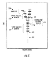
- FIG. 5 is a notional simplified diagram representing relative range of a target versus time
- FIG. 6 is a logic or control flow chart or diagram illustrating steps of processing in the coasting function of FIG. 4 .
- Coasting is defined as estimating the states of the target when measurements are not available. The ability to coast a target is dependent upon the last known state of the target.
- the velocity which is part of the Cartesian states produced by Kalman filter 316 of FIG. 3 , is fundamentally limited in accuracy when measurements are sparse.
- a method according to an aspect of the invention provides improved range-state coasting for ballistic targets using a limited set of radar observations or when the flow of radar observations is interrupted. In radar applications, range-state filtering converges very quickly because of the high precision of the range and Doppler data. Coasting in range-state models is or may be less satisfactory than desired because of the difficulty of predicting the effects of gravity in the direction of the range vector.
- filtering in range-state is subject to the effects of centrifugal accelerations.
- the effect of gravity and centrifugal accelerations on a ballistic target in Cartesian coordinates is easy to model.
- the problem with the Cartesian model is that it converges much more slowly than the range-state filter because of the noisier measurements in cross-range (a direction transverse to the range direction).
- the method according to aspects of the invention takes advantage of the fast convergence of range filtering to “jump start” the Cartesian model.
- the improved state of the Cartesian model is used to predict gravity and centrifugal accelerations that influence the range states. Range-state coasting is improved with these effects taken into account.
- Tracking processor 400 of FIG. 4 is generally similar to FIG. 3 , but incorporates functions according to aspects of the invention.
- the received measurements are applied over path 221 in common to an instantaneous range-state filter 412 and to a Cartesian coordinate converter 314 .
- Cartesian coordinate information produced by converter 314 is applied to a Cartesian Kalman filter 316 .
- Cartesian coordinate converter 314 and Cartesian Kalman filter 316 are both essentially identical to those described in conjunction with FIG. 3 .
- Perpendicular speed estimator block 430 computes the instantaneous perpendicular speed of the target at the instants established by block 412 .
- Cartesian filter state updater 432 of FIG. 4 takes the target states from the Cartesian Kalman filter 316 and the target states from instantaneous perpendicular speed estimator block 430 and updates or improves (jump-starts) the Cartesian filter states.
- N Cartesian velocity state (X velocity , Y velocity , Z velocity ) N (where the subscript ‘N’ represents the Nth member of a sequence of ‘K’ measurements; ‘N’ is typically, thought not necessarily, the mid-point of the sequence) using the following update:
- v 1 _ r ⁇ N - r -> ⁇ ⁇ g -> r N ⁇ ⁇
- ⁇ ⁇ r -> ⁇ [ X Y Z ] N ⁇ [ X Y Z ] N ⁇ ⁇ ⁇ ⁇
- v -> ⁇ 1 _ ( I - r ⁇ -> ⁇ r ⁇ -> T ) ⁇ [ X veclocity Y veclocity Z veclocity ] N ⁇ ( I - r ⁇ -> ⁇ r ⁇ -> T ) ⁇ [ X veclocity Y veclocity Z veclocity ] N ⁇
- the Nth Cartesian velocity state is replaced with the improved Cartesian velocity state:
- FIG. 6 is a simplified logic flow chart or diagram representing the steps performed in coaster block 434 .
- the logic begins at a START block 610 .
- coaster block 434 of FIG. 4 For each increment in time, coaster block 434 of FIG. 4 :
- [ r r . ] k + 1 [ r r . ] k + 1 + [ 0.5 ⁇ ⁇ ⁇ ⁇ t 2 ⁇ ⁇ ⁇ t ] + [ 0.5 ⁇ g ⁇ ⁇ ⁇ ⁇ ⁇ t 2 g ⁇ ⁇ ⁇ ⁇ ⁇ t ]
- Instantaneous range-state filter block 412 of FIG. 4 includes a forward range-state filter 450 and a backward range-state filter 452 , both of which receive the received measurements from path 221 .
- Forward range-state filter 450 is a filter that processes measurements 1 through N as a forward sequence (i.e. 1, 2, 3, . . . , N).
- Backward range-state filter 452 is a filter that processes measurements N through K in reverse sequence (i.e. K, K ⁇ 1, K ⁇ 2, . . . , N+1, N). As with the forward range-state filter 450 , the effects of gravity are not modeled.
- the filtered outputs of blocks 450 and 452 are applied to an averager or integrator block 454 .
- Averager block 454 of FIG. 4 takes a mean average of the results of blocks 450 and 452 , to thereby produce target states and covariance for application to path 413 , block 430 , and block 434 .
- FIG. 5 is a notional simplified diagram representing relative range of a target versus time for the purpose of illustrating regions of algorithm applicability.
- dotted line 510 represents the range of the target (prior to detection) relative to a ballistic trajectory.
- the target is detected.
- the cross-lines in region 514 represent the apparent length of the target.
- the target splits into two objects, which may be viewed as being a reentry vehicle and a decoy. In the region or time interval 520 between points 516 and 517 , the two objects cannot be individually resolved. This lack of resolution distorts the true trajectories of the objects.
- Time region 522 represents a short ballistic segment, with a lessening range with increasing time.
- the time illustrated as 524 represents an evasive maneuver. If the states of the targets were to be based upon a combination of data from times 522 and 524 , then the actual state or location of the reentry vehicle might be incorrectly estimated. The most critical portion of the target state for the purpose of countermeasures is the velocity.
- Such short track segments may be caused by lack of data, the editing out or deleting of unresolved objects, and the editing out or deleting of track segments which include maneuvers, such as segment 524 of FIG. 5 . This last may be viewed as being or including the localization and/or characterization of maneuver track segments.
- a method is for generating target ( 18 ) location and state to support trajectory coasting (in region 520 ).
- the method comprises the steps of Cartesian-coordinate filtering ( 314 , 316 ) range and angle information (from 218 by way of 221 ) to thereby produce Cartesian-coordinate state information (on path 435 ) having a first quality.
- Range and Doppler information are filtered ( 412 ) to produce filtered range state including range acceleration (on path 413 ).
- the instantaneous perpendicular speed is determined ( 430 ) from the range acceleration.
- Cartesian velocity is estimated ( 432 ) from the instantaneous perpendicular speed and from the Cartesian-coordinate state information having a first quality, and combining the Cartesian-coordinate state information with the estimated Cartesian velocity to thereby produce Cartesian state information with a higher quality than the first quality.
- the estimated Cartesian velocity is propagated in time ( 434 ) to thereby produce range acceleration information, and the range acceleration information is combined with the range state estimate to thereby produce target location and state (on paths 436 and 438 ).
- a particular mode of the method includes the further step of discriminating among targets by kinematic estimation.
- a further mode comprises the step of initiating countermeasures ( 226 ) to the targets in response to the kinematic estimation.
- a method for determining the location and velocity of a target in terms of range-state and Cartesian state comprises the steps of sensing the target ( 18 ) with a radar ( 212 ), to thereby generate ( 218 ) measurement data, and determining ( 412 ) from the measurement data instantaneous range-state and covariance (on path 413 ).
- the method also includes the step of estimating, ( 430 ) from the instantaneous range-state and covariance, the instantaneous perpendicular speed of the target.
- the measurement data is converted into Cartesian coordinates ( 314 ) to thereby produce measurement data in Cartesian coordinates.
- the measurement data in Cartesian coordinates is Kalman filtered ( 316 ) to thereby produce filtered Cartesian states and covariance.
- the filtered Cartesian states and covariance are updated ( 432 ) with the instantaneous perpendicular speed to thereby produce improved Cartesian states and improved covariance with improved target velocity.
- the improved Cartesian states and improved covariance are coasted ( 434 ) at times when the measurement data is interrupted, or is of questionable quality, by the steps of:
- the step of computing the centrifugal acceleration ( 618 ) is performed according to
- ⁇ is the centrifugal acceleration
- ⁇ right arrow over (v) ⁇ ⁇ is the perpendicular Cartesian velocity vector
- r is the range.
- [ r r . ] k + 1 [ r r . ] k + 1 + [ 0.5 ⁇ ⁇ ⁇ ⁇ t 2 ⁇ ⁇ ⁇ t ] + [ 0.5 ⁇ g ⁇ ⁇ ⁇ ⁇ ⁇ t 2 g ⁇ ⁇ ⁇ ⁇ ⁇ t ]
Landscapes
- Engineering & Computer Science (AREA)
- Radar, Positioning & Navigation (AREA)
- Remote Sensing (AREA)
- Physics & Mathematics (AREA)
- Computer Networks & Wireless Communication (AREA)
- General Physics & Mathematics (AREA)
- Electromagnetism (AREA)
- Radar Systems Or Details Thereof (AREA)
Abstract
Description
-
- propagating the improved Cartesian state and improved covariance, and “adding” the effects of gravity in Cartesian coordinates, or more specifically calculating the direction and effects of gravity in Cartesian coordinates;
- calculating the contribution of gravity in the direction of the radar line-of-sight using the improved Cartesian state;
- computing the centrifugal acceleration with respect to the range-state using the improved target velocity in Cartesian coordinates;
- propagating the range-state; and
- adding the effects of gravity and centrifugal acceleration on the range-state as computed in the steps of calculating and computing, thereby generating range-state.
-
- In another particular mode of the method for determining the location and velocity of a target, the step of propagating the range-state (620) is performed by
-
- In yet another particular mode of the method for determining the location and velocity of a target, the step of adding the effects of gravity and centrifugal acceleration to the range-state (622) is performed by
-
- where {tilde over (g)} is the projection of gravity into the line-of-sight extending between the locations of the radar and the target; and
- the location of the target is computed by the Cartesian filter.
The Nth Cartesian velocity state is replaced with the improved Cartesian velocity state:
In the above equations, rN, {dot over (r)}N, {umlaut over (r)}N are range, range-rate, and range-acceleration, respectively. These are elements of range-state, the product of
-
- 1) Propagates the improved Cartesian state(s) which it receives from Cartesian Filter State Updater block 432, as suggested by
block 612 ofFIG. 6 . It also, for each update, calculates the direction and effect(s) of gravity, and adds those effect(s) of gravity in Cartesian coordinates to the propagated Cartesian state(s), as suggested byblock 614; - 2) Calculates the contribution of gravity in the direction of the radar line-of-sight (LOS) using the propagated Cartesian state(s), as suggested by
block 616; - 3) Computes the centrifugal acceleration with respect to the current propagated radar position or Cartesian state(s) according to
- 1) Propagates the improved Cartesian state(s) which it receives from Cartesian Filter State Updater block 432, as suggested by
-
-
- where
- α is the centrifugal acceleration;
- {right arrow over (v)}⊥ is the perpendicular Cartesian velocity vector
- as suggested by
block 618 ofFIG. 6 ; - 4) Propagates the range-state (received from
block 412 ofFIG. 4 by way of path 413) by
-
-
-
- where Δt is the update interval
- as suggested by
block 620 ofFIG. 6 ; and
- 5) Adds the effects of gravity and centrifugal acceleration to the range-state (as computed in steps 2) & 3) by computing
-
-
-
- where {tilde over (g)} is the projection of gravity into the line-of-sight;
- the line-of-sight extends between the locations of the radar and the target; and
- the location of the target is computed by the Cartesian filter.
as suggested byblock 622 ofFIG. 6 .
Steps 1) through 5) are repeated for each coasting step. The output ofcoaster block 434 ofFIG. 4 is applied overpaths discrimination block 320, already described in conjunction withFIG. 3 .
-
-
- propagating (612) the improved Cartesian state and improved covariance, and “adding” (614) to the improved Cartesian state the effects of gravity in Cartesian coordinates, or more specifically calculating the direction and effects of gravity on the improved Cartesian state;
- calculating (616) the contribution of gravity in the direction of the radar line-of-sight using the improved Cartesian state;
- computing (618) the centrifugal acceleration with respect to the range-state using the improved target velocity in Cartesian coordinates;
- propagating (620) the range-state; and
- adding (622) the effects of gravity and centrifugal acceleration on the range-state as computed in the steps of calculating and computing, thereby generating range-state.
-
- In another particular mode of the method for determining the location and velocity of a target, the step of propagating the range-state (620) is performed by
-
- In yet another particular mode of the method for determining the location and velocity of a target, the step of adding the effects of gravity and centrifugal acceleration to the range-state (622) is performed by
-
- where {tilde over (g)} is the projection of gravity into the line-of-sight extending between the locations of the radar and the target; and
- the location of the target is computed by the Cartesian filter.
Claims (16)
Priority Applications (1)
| Application Number | Priority Date | Filing Date | Title |
|---|---|---|---|
| US12/250,207 US8149159B1 (en) | 2008-10-13 | 2008-10-13 | Radar coasting during data dropout |
Applications Claiming Priority (1)
| Application Number | Priority Date | Filing Date | Title |
|---|---|---|---|
| US12/250,207 US8149159B1 (en) | 2008-10-13 | 2008-10-13 | Radar coasting during data dropout |
Publications (1)
| Publication Number | Publication Date |
|---|---|
| US8149159B1 true US8149159B1 (en) | 2012-04-03 |
Family
ID=45877360
Family Applications (1)
| Application Number | Title | Priority Date | Filing Date |
|---|---|---|---|
| US12/250,207 Expired - Fee Related US8149159B1 (en) | 2008-10-13 | 2008-10-13 | Radar coasting during data dropout |
Country Status (1)
| Country | Link |
|---|---|
| US (1) | US8149159B1 (en) |
Citations (1)
| Publication number | Priority date | Publication date | Assignee | Title |
|---|---|---|---|---|
| US4783744A (en) * | 1986-12-08 | 1988-11-08 | General Dynamics, Pomona Division | Self-adaptive IRU correction loop design interfacing with the target state estimator for multi-mode terminal handoff |
-
2008
- 2008-10-13 US US12/250,207 patent/US8149159B1/en not_active Expired - Fee Related
Patent Citations (1)
| Publication number | Priority date | Publication date | Assignee | Title |
|---|---|---|---|---|
| US4783744A (en) * | 1986-12-08 | 1988-11-08 | General Dynamics, Pomona Division | Self-adaptive IRU correction loop design interfacing with the target state estimator for multi-mode terminal handoff |
Similar Documents
| Publication | Publication Date | Title |
|---|---|---|
| US7663528B1 (en) | Missile boost-ballistic estimator | |
| US8106814B2 (en) | Method of estimating the elevation of a ballistic projectile | |
| US7924213B2 (en) | Method of and device for tracking an object | |
| US7764217B2 (en) | Surface RF emitter passive ranging accuracy confirmation algorithm | |
| KR101641614B1 (en) | Ladar backtracking of wake turbulence trailing an airborne target for point-of-origin estimation and target classification | |
| US8358238B1 (en) | Maneuvering missile engagement | |
| WO2017039747A1 (en) | Magnetic wake detector | |
| IL238877A (en) | Kalman filtering with indirect noise measurements | |
| EP3146356B1 (en) | Direct geolocation from tdoa, fdoa, and agl | |
| US20150268329A1 (en) | Passive ranging of a target | |
| CN111121770B (en) | Interactive multi-missile multi-model flight path fusion method | |
| US8502126B2 (en) | System and method for navigating an object | |
| JP3172541B2 (en) | Missile guidance system | |
| US7185844B2 (en) | Methods and systems for guiding an object to a target using an improved guidance law | |
| US7187320B1 (en) | Matched maneuver detector | |
| RU2617373C1 (en) | Optimal method of binding to mobile ground target and forecasting its parameters based on modified, invariant to underlying surface relief, elevation procedure of distance calculation | |
| US8149159B1 (en) | Radar coasting during data dropout | |
| CN115096315B (en) | Spacecraft target maneuvering detection method aiming at sparse data | |
| KR102501275B1 (en) | Precise trajectory prediction method and apparatus of a highly maneuvering target through flight dynamics estimation and multipath suppression | |
| Raj et al. | Estimation of line-of-sight rate in a homing Missile Guidance loop using optimal filters | |
| KR101837845B1 (en) | System and method for obtaining information of underwater target | |
| CN112684411B (en) | Underwater target positioning method based on improved arrival frequency difference | |
| JP7306030B2 (en) | Target motion estimation device and target motion estimation method | |
| Kim et al. | Ballistic object trajectory and launch point estimation from radar measurements using long-short term memory networks | |
| RU2048684C1 (en) | Method for tracking maneuvering aerial target |
Legal Events
| Date | Code | Title | Description |
|---|---|---|---|
| AS | Assignment |
Owner name: LOCKHEED MARTIN CORPORATION, MARYLAND Free format text: ASSIGNMENT OF ASSIGNORS INTEREST;ASSIGNOR:YANG, ROBERT E.;REEL/FRAME:021674/0046 Effective date: 20081010 |
|
| ZAAA | Notice of allowance and fees due |
Free format text: ORIGINAL CODE: NOA |
|
| ZAAB | Notice of allowance mailed |
Free format text: ORIGINAL CODE: MN/=. |
|
| FEPP | Fee payment procedure |
Free format text: PAYOR NUMBER ASSIGNED (ORIGINAL EVENT CODE: ASPN); ENTITY STATUS OF PATENT OWNER: LARGE ENTITY |
|
| STCF | Information on status: patent grant |
Free format text: PATENTED CASE |
|
| FPAY | Fee payment |
Year of fee payment: 4 |
|
| MAFP | Maintenance fee payment |
Free format text: PAYMENT OF MAINTENANCE FEE, 8TH YEAR, LARGE ENTITY (ORIGINAL EVENT CODE: M1552); ENTITY STATUS OF PATENT OWNER: LARGE ENTITY Year of fee payment: 8 |
|
| FEPP | Fee payment procedure |
Free format text: MAINTENANCE FEE REMINDER MAILED (ORIGINAL EVENT CODE: REM.); ENTITY STATUS OF PATENT OWNER: LARGE ENTITY |
|
| LAPS | Lapse for failure to pay maintenance fees |
Free format text: PATENT EXPIRED FOR FAILURE TO PAY MAINTENANCE FEES (ORIGINAL EVENT CODE: EXP.); ENTITY STATUS OF PATENT OWNER: LARGE ENTITY |
|
| STCH | Information on status: patent discontinuation |
Free format text: PATENT EXPIRED DUE TO NONPAYMENT OF MAINTENANCE FEES UNDER 37 CFR 1.362 |