US8098836B2 - Active vibratory noise control apparatus - Google Patents
Active vibratory noise control apparatus Download PDFInfo
- Publication number
- US8098836B2 US8098836B2 US11/987,618 US98761807A US8098836B2 US 8098836 B2 US8098836 B2 US 8098836B2 US 98761807 A US98761807 A US 98761807A US 8098836 B2 US8098836 B2 US 8098836B2
- Authority
- US
- United States
- Prior art keywords
- vibratory noise
- filter coefficient
- vibratory
- error signal
- signal
- Prior art date
- Legal status (The legal status is an assumption and is not a legal conclusion. Google has not performed a legal analysis and makes no representation as to the accuracy of the status listed.)
- Active, expires
Links
Images


Classifications
-
- G—PHYSICS
- G10—MUSICAL INSTRUMENTS; ACOUSTICS
- G10K—SOUND-PRODUCING DEVICES; METHODS OR DEVICES FOR PROTECTING AGAINST, OR FOR DAMPING, NOISE OR OTHER ACOUSTIC WAVES IN GENERAL; ACOUSTICS NOT OTHERWISE PROVIDED FOR
- G10K11/00—Methods or devices for transmitting, conducting or directing sound in general; Methods or devices for protecting against, or for damping, noise or other acoustic waves in general
- G10K11/16—Methods or devices for protecting against, or for damping, noise or other acoustic waves in general
- G10K11/175—Methods or devices for protecting against, or for damping, noise or other acoustic waves in general using interference effects; Masking sound
- G10K11/178—Methods or devices for protecting against, or for damping, noise or other acoustic waves in general using interference effects; Masking sound by electro-acoustically regenerating the original acoustic waves in anti-phase
- G10K11/1787—General system configurations
- G10K11/17879—General system configurations using both a reference signal and an error signal
- G10K11/17883—General system configurations using both a reference signal and an error signal the reference signal being derived from a machine operating condition, e.g. engine RPM or vehicle speed
-
- G—PHYSICS
- G10—MUSICAL INSTRUMENTS; ACOUSTICS
- G10K—SOUND-PRODUCING DEVICES; METHODS OR DEVICES FOR PROTECTING AGAINST, OR FOR DAMPING, NOISE OR OTHER ACOUSTIC WAVES IN GENERAL; ACOUSTICS NOT OTHERWISE PROVIDED FOR
- G10K11/00—Methods or devices for transmitting, conducting or directing sound in general; Methods or devices for protecting against, or for damping, noise or other acoustic waves in general
- G10K11/16—Methods or devices for protecting against, or for damping, noise or other acoustic waves in general
- G10K11/175—Methods or devices for protecting against, or for damping, noise or other acoustic waves in general using interference effects; Masking sound
- G10K11/178—Methods or devices for protecting against, or for damping, noise or other acoustic waves in general using interference effects; Masking sound by electro-acoustically regenerating the original acoustic waves in anti-phase
- G10K11/1781—Methods or devices for protecting against, or for damping, noise or other acoustic waves in general using interference effects; Masking sound by electro-acoustically regenerating the original acoustic waves in anti-phase characterised by the analysis of input or output signals, e.g. frequency range, modes, transfer functions
- G10K11/17821—Methods or devices for protecting against, or for damping, noise or other acoustic waves in general using interference effects; Masking sound by electro-acoustically regenerating the original acoustic waves in anti-phase characterised by the analysis of input or output signals, e.g. frequency range, modes, transfer functions characterised by the analysis of the input signals only
- G10K11/17823—Reference signals, e.g. ambient acoustic environment
-
- G—PHYSICS
- G10—MUSICAL INSTRUMENTS; ACOUSTICS
- G10K—SOUND-PRODUCING DEVICES; METHODS OR DEVICES FOR PROTECTING AGAINST, OR FOR DAMPING, NOISE OR OTHER ACOUSTIC WAVES IN GENERAL; ACOUSTICS NOT OTHERWISE PROVIDED FOR
- G10K11/00—Methods or devices for transmitting, conducting or directing sound in general; Methods or devices for protecting against, or for damping, noise or other acoustic waves in general
- G10K11/16—Methods or devices for protecting against, or for damping, noise or other acoustic waves in general
- G10K11/175—Methods or devices for protecting against, or for damping, noise or other acoustic waves in general using interference effects; Masking sound
- G10K11/178—Methods or devices for protecting against, or for damping, noise or other acoustic waves in general using interference effects; Masking sound by electro-acoustically regenerating the original acoustic waves in anti-phase
- G10K11/1783—Methods or devices for protecting against, or for damping, noise or other acoustic waves in general using interference effects; Masking sound by electro-acoustically regenerating the original acoustic waves in anti-phase handling or detecting of non-standard events or conditions, e.g. changing operating modes under specific operating conditions
-
- G—PHYSICS
- G10—MUSICAL INSTRUMENTS; ACOUSTICS
- G10K—SOUND-PRODUCING DEVICES; METHODS OR DEVICES FOR PROTECTING AGAINST, OR FOR DAMPING, NOISE OR OTHER ACOUSTIC WAVES IN GENERAL; ACOUSTICS NOT OTHERWISE PROVIDED FOR
- G10K11/00—Methods or devices for transmitting, conducting or directing sound in general; Methods or devices for protecting against, or for damping, noise or other acoustic waves in general
- G10K11/16—Methods or devices for protecting against, or for damping, noise or other acoustic waves in general
- G10K11/175—Methods or devices for protecting against, or for damping, noise or other acoustic waves in general using interference effects; Masking sound
- G10K11/178—Methods or devices for protecting against, or for damping, noise or other acoustic waves in general using interference effects; Masking sound by electro-acoustically regenerating the original acoustic waves in anti-phase
- G10K11/1785—Methods, e.g. algorithms; Devices
- G10K11/17853—Methods, e.g. algorithms; Devices of the filter
- G10K11/17854—Methods, e.g. algorithms; Devices of the filter the filter being an adaptive filter
-
- G—PHYSICS
- G10—MUSICAL INSTRUMENTS; ACOUSTICS
- G10K—SOUND-PRODUCING DEVICES; METHODS OR DEVICES FOR PROTECTING AGAINST, OR FOR DAMPING, NOISE OR OTHER ACOUSTIC WAVES IN GENERAL; ACOUSTICS NOT OTHERWISE PROVIDED FOR
- G10K11/00—Methods or devices for transmitting, conducting or directing sound in general; Methods or devices for protecting against, or for damping, noise or other acoustic waves in general
- G10K11/16—Methods or devices for protecting against, or for damping, noise or other acoustic waves in general
- G10K11/175—Methods or devices for protecting against, or for damping, noise or other acoustic waves in general using interference effects; Masking sound
- G10K11/178—Methods or devices for protecting against, or for damping, noise or other acoustic waves in general using interference effects; Masking sound by electro-acoustically regenerating the original acoustic waves in anti-phase
- G10K11/1785—Methods, e.g. algorithms; Devices
- G10K11/17857—Geometric disposition, e.g. placement of microphones
-
- G—PHYSICS
- G10—MUSICAL INSTRUMENTS; ACOUSTICS
- G10K—SOUND-PRODUCING DEVICES; METHODS OR DEVICES FOR PROTECTING AGAINST, OR FOR DAMPING, NOISE OR OTHER ACOUSTIC WAVES IN GENERAL; ACOUSTICS NOT OTHERWISE PROVIDED FOR
- G10K2210/00—Details of active noise control [ANC] covered by G10K11/178 but not provided for in any of its subgroups
- G10K2210/10—Applications
- G10K2210/128—Vehicles
- G10K2210/1282—Automobiles
-
- G—PHYSICS
- G10—MUSICAL INSTRUMENTS; ACOUSTICS
- G10K—SOUND-PRODUCING DEVICES; METHODS OR DEVICES FOR PROTECTING AGAINST, OR FOR DAMPING, NOISE OR OTHER ACOUSTIC WAVES IN GENERAL; ACOUSTICS NOT OTHERWISE PROVIDED FOR
- G10K2210/00—Details of active noise control [ANC] covered by G10K11/178 but not provided for in any of its subgroups
- G10K2210/30—Means
- G10K2210/301—Computational
- G10K2210/3046—Multiple acoustic inputs, multiple acoustic outputs
Definitions
- the present invention relates to an active vibratory noise control apparatus for canceling vibratory noises produced by a vibratory noise source by means of vibratory noise canceling sounds that are opposite in phase to the vibratory noise, and more particularly to an active vibratory noise control apparatus for reducing vibratory noises produced within a passenger compartment of a vehicle by a vibratory noise source such as the vehicle engine.
- Conventional active vibratory noise control apparatus operate by detecting noise in the passenger compartment of a vehicle by means of a microphone disposed centrally over the front seats near the position of an ear of a passenger, then generating a signal that is opposite in phase to an output signal produced by the microphone based on the noise, and outputting canceling sounds based on the generated signal into the passenger compartment from two speakers that are mounted respectively in the left and right doors alongside of the front seats, for thereby reducing the noise at the microphone (see Japanese Laid-Open Patent Publication No. 2003-47097).
- a phase shifter generates signals by shifting the central frequency of the phase rotation of the signal in an opposite phase, and supplies the generated signals to the respective speakers. In this manner, even when the frequency of the sound in the passenger compartment becomes higher, the canceling sounds from the left and right speakers are prevented from interfering with each other.
- the active vibratory noise control apparatus since the phase shifter is added to the apparatus for reducing noise in the passenger compartment, and the opposite phase signal is rotated in phase by means of the phase shifter, the active vibratory noise control apparatus has a complex configuration and is high in cost.
- Another object of the present invention is to provide an active vibratory noise control apparatus, which is reduced in cost and is capable of reducing vibratory noise within a wide space.
- an active vibratory noise control apparatus basically comprises a reference wave signal generator for generating a reference wave signal having a frequency based on the frequency of vibratory noise generated by a vibratory noise source, an adaptive filter for outputting a control signal based on the reference wave signal in order to cancel the vibratory noise, vibratory noise canceller for outputting vibratory noise canceling sounds based on the control signal, error signal detector for outputting an error signal based on the difference between the vibratory noise and the vibratory noise canceling sounds, corrector for correcting the reference wave signal and outputting a corrected reference wave signal as a reference signal to the error signal detector, based on a corrective value corresponding to signal transfer characteristics from the vibratory noise canceller, and filter coefficient updater for sequentially updating a filter coefficient of the adaptive filter in order to minimize the error signal based on the error signal and the reference signal.
- the vibratory noise canceller includes at least two first vibratory noise canceller disposed near a first space, and at least one second vibratory noise canceller disposed near a second space.
- the error signal detector includes either both at least one first error signal detector disposed near the first space, and at least one second error signal detector disposed near the second space, or only the first error signal detector.
- the active vibratory noise control apparatus also includes a switcher for changing the corrective value of the corrector from a first corrective value corresponding to signal transfer characteristics from the first vibratory noise canceller to the first error signal detector, or from a second corrective value corresponding to signal transfer characteristics from the second vibratory noise canceller to the second error signal detector, to a third corrective value corresponding to signal transfer characteristics from the second vibratory noise canceller to the first error signal detector, and changing the vibratory noise canceller for outputting the vibratory noise canceling sounds into the first space from the first vibratory noise canceller to the second vibratory noise canceller, when control characteristics of the vibratory noise have changed across a preset threshold value.
- the switcher changes the corrective value of the corrector, and also changes combinations of the vibratory noise canceller for outputting the vibratory noise canceling sounds and the error signal detector for outputting the error signal.
- the threshold value is set to the predetermined frequency.
- the switcher changes the combinations of the vibratory noise canceller and the error signal detector so as to avoid interference between the vibratory noise canceling sounds.
- the vibratory noise can efficiently be reduced at a location spaced from the first error signal detector.
- the vibratory noise canceling sounds output from the vibratory noise canceller are prevented from interfering with each other, without the need for the phase shifter disclosed in Japanese Laid-Open Patent Publication No. 2004-47097, vibratory noise can be reduced by a simpler arrangement, even when the frequency of the vibratory noise changes. Also, since a phase shifter is not used, the active vibratory noise control apparatus is relatively low in cost. Since canceling sounds are prevented from interfering with each other by changing combinations of the vibratory noise canceller and the error signal detector, vibratory noises can be reduced within a wider space.
- Control characteristics of the vibratory noise are defined by characteristics relative to the vibratory noise to be reduced by the active vibratory noise control apparatus, and may be represented by the frequency of the vibratory noise, for example.
- the threshold value refers to a threshold value corresponding to the frequency of the vibratory noise, at which the vibratory noise canceling sounds interfere with each other when two of the first vibratory noise canceller output vibratory noise canceling sounds into the first space.
- the first space refers to a space in which vibratory noise is reduced by the first vibratory noise canceller and the first error signal detector disposed near the first space when the control characteristics are lower than the threshold value, and wherein the vibratory noise is reduced by the second vibratory noise canceller disposed near the second space when the control characteristics are higher than the threshold value.
- the second space refers to a space in which vibratory noise is reduced by the second vibratory noise canceller disposed near the second space when the control characteristics are lower than the threshold value.
- the switcher preferably should stop outputting vibratory noise canceling sounds from the first vibratory noise canceller when the control characteristics of the vibratory noise have changed across the preset threshold value. Therefore, the vibratory noise within the first space can reliably be reduced even if the control characteristics of the vibratory noise change.
- the switcher changes the corrective value of the corrector from the first corrective value to a fourth corrective value corresponding to signal transfer characteristics from the first vibratory noise canceller to the second error signal detector, and from the second corrective value to the third corrective value, changes the vibratory noise canceller for outputting the vibratory noise canceling sounds into the first space from the first vibratory noise canceller to the second vibratory noise canceller, and changes the vibratory noise canceller for outputting the vibratory noise canceling sounds into the second space from the second vibratory noise canceller to the first vibratory noise canceller, when the control characteristics of the vibratory noise have changed across the preset threshold value. Vibratory noises within the first and second spaces can thus reliably be reduced even if the control characteristics of the vibratory noise change.
- the switcher includes a control signal supply switcher for changing the vibratory noise canceller to be supplied with the control signal output from the adaptive filter, and an error signal switcher for changing the error signal detector for supplying the error signal to the filter coefficient updater, when the control characteristics of the vibratory noise have changed across the preset threshold value. Vibratory noise can thus be reduced efficiently.
- the vibratory noise source comprises an engine of a vehicle
- the control characteristics of the vibratory noise represent the frequency of the vibratory noise generated by the engine or by the rotational speed of an output shaft of the engine. If the first space is disposed around the front seats or the rear seat of the passenger compartment of the vehicle, then the vibratory noise in the passenger compartment can reliably be reduced.
- the vibratory noise source comprises a propeller shaft or tire wheels of the vehicle, and the control characteristics of the vibratory noise represent the rotational frequency of the propeller shaft or the tire wheels, or the speed of the vehicle.
- the control characteristics of the vibratory noise represent the rotational frequency of the propeller shaft or the tire wheels, or the speed of the vehicle.
- the switcher preferably comprises a corrected filter coefficient calculator for calculating a corrected filter coefficient by multiplying the filter coefficient by a predetermined value of less than 1 , and a filter coefficient switcher for supplying the corrected filter coefficient, rather than the filter coefficient, to the adaptive filter when the control characteristics are higher than the threshold value.
- the vibratory noise canceller may be operated in a fade-out mode, for gradually reducing the vibratory noise canceling sounds rather than stopping output of the vibratory noise canceling sounds upon changing the vibratory noise canceller. Accordingly, an uncomfortable vibratory noise is prevented from being generated when the vibratory noise canceller are switched.
- the switcher may impart hysteresis to the threshold value when the control characteristics are higher than the threshold value and lower than the threshold value, so that combinations can be changed efficiently even when the frequency of the vibratory noise varies near a frequency corresponding to the threshold value.
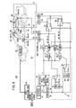
- FIG. 1 is a block diagram of an active vibratory noise control apparatus according to a first embodiment of the present invention
- FIG. 2 is a plan view of a vehicle incorporating therein the active vibratory noise control apparatus shown in FIG. 1 ;
- FIG. 3 is a front elevational view showing the layout of speakers and a microphone near front seats in the vehicle shown in FIG. 2 ;
- FIG. 4 is a plan view of a vehicle incorporating therein the active vibratory noise control apparatus, with a single speaker disposed behind a rear seat in the vehicle;
- FIG. 5 is a block diagram of an active vibratory noise control apparatus according to a second embodiment of the present invention.
- FIG. 6 is a block diagram of an active vibratory noise control apparatus according to a third embodiment of the present invention.
- FIG. 7 is a block diagram of an active vibratory noise control apparatus according to a fourth embodiment of the present invention.
- FIG. 8 is a block diagram of an active vibratory noise control apparatus according to a fifth embodiment of the present invention.
- FIGS. 1 through 4 show an active vibratory noise control apparatus (hereinafter referred to as “ANC”) 10 A according to a first embodiment of the present invention, which is applied to reduce vibratory noise within a passenger compartment (space) 14 of a vehicle 12 .
- ANC active vibratory noise control apparatus
- the ANC 10 A includes a microphone (first error signal detector) 20 disposed on a roof lining near headrests 18 a , 18 b , i.e., near to an ear of a passenger (not shown), centrally over the front seats 16 a , 16 b in the passenger compartment 14 , and another microphone (second error signal detecting means, second error signal detector) 26 disposed on a roof lining near a headrest 24 , centrally over a rear seat 22 inside the passenger compartment 14 .
- first error signal detector first error signal detector
- the ANC 10 A also includes a speaker 28 a mounted on a left door near to the front seats 16 a , 16 b , a speaker 28 b mounted on a right door near to the front seats 16 a , 16 b , and two speakers 30 a , 30 b disposed behind the rear seat 22 .
- the ANC 10 A may have a single speaker 30 disposed behind the rear seat 22 , rather than the two speakers 30 a and 30 b .
- the speakers (vibratory noise canceller) 28 a , 28 b , 30 , 30 a , 30 b shown in FIGS. 1 through 4 are provided as speakers of an audio system that is incorporated as standard equipment in the vehicle 12 .
- the ANC 10 A also has an ANC controller 32 including a microcomputer.
- the ANC controller 32 basically comprises a frequency detector 44 , a reference wave signal generating means (a reference wave signal generator) 46 , a pair of adaptive filters 48 , 54 , a pair of filter coefficient updating means (filter coefficient updater) 52 , 58 , and a pair of correcting means (corrector) 90 , 92 .
- the frequency detector 44 comprises a frequency counter for detecting the frequency fe of an engine rotation signal that is output from a fuel injection ECU 42 for controlling an engine 40 on the vehicle 12 .
- the engine rotation signal is output from a Hall device or the like, not shown, per each revolution of the output shaft of the engine 40 .
- the engine rotation signal is a signal that correlates with noise generated from the engine 40 , e.g., engine sounds and periodic noise caused by vibrational forces produced upon rotation of the output shaft of the engine 40 , and vibratory noise caused by vibrations of the engine 40 .
- the reference wave signal generating means 46 generates a reference wave signal x of predetermined harmonics with respect to a fundamental frequency, which is given as a frequency fe from the frequency detector 44 .
- the adaptive filter 48 generates a control signal S 0 by multiplying the reference signal x by a filter coefficient Wfr, and the adaptive filter 54 generates a control signal S 1 by multiplying the reference signal x by a filter coefficient Wrr.
- the control signals S 0 , S 1 serve to cancel out vibratory noise (hereinafter referred to as “engine noise”) that occurs in the passenger compartment 14 as a result of vibratory noise produced from the engine 40 .
- the control signals S 0 , S 1 are converted by DA converters (DACs) 60 , 62 from digital signals into analog signals, which are output to the speakers 28 a , 28 b , 30 , 30 a , 30 b.
- DACs DA converters
- the speakers 28 a , 28 b , 30 , 30 a , 30 b output canceling sounds (vibratory noise canceling sounds) into the passenger compartment 14 for canceling engine noise based on the control signals S 0 , S 1 .
- the microphone 20 outputs the difference between the canceling sounds from the speakers (first vibratory noise canceling means, first vibratory noise canceller) 28 a , 28 b or the speakers (second vibratory noise canceling means, second vibratory noise canceller) 30 , 30 a , 30 b and the engine sound as an error signal e 0 to the ANC controller 32 .
- the microphone 26 also outputs the difference between the canceling sounds from the speakers 30 , 30 a , 30 b and the engine sound as an error signal e 1 to the ANC controller 32 .
- the correcting means 90 generates a reference signal r 0 by correcting the reference wave signal x with a corrective value, representing transfer characteristics C ⁇ 00 (first corrective value) that is simulative of transfer characteristics (first transfer characteristics) C 00 from the speakers 28 a , 28 b to the microphone 20 , and outputs the reference signal r 0 to the filter coefficient updating means 52 .
- the correcting means 92 generates a reference signal r 1 by correcting the reference wave signal x with a corrective value, representing predetermined transfer characteristics C ⁇ rr, and outputs the reference signal r 1 to the filter coefficient updating means 58 .
- the transfer characteristics C ⁇ 00 are transfer characteristics from the input of the DAC 60 to the output of an AD converter (ADC) 64 , including transfer characteristics C 00
- the transfer characteristics C ⁇ rr are transfer characteristics C ⁇ 11 (second corrective value) from the input of the DAC 62 to the output of an ADC 66 , including transfer characteristics C 11 from the speakers 30 , 30 a , 30 b to the microphone 26 , or transfer characteristics C ⁇ 10 (third corrective value) from the input of the DAC 62 to the output of the ADC 64 , including transfer characteristics C 10 from the speakers 30 , 30 a , 30 b to the microphone 20 .
- ADC AD converter
- Each of the filter coefficient updating means 52 , 58 comprises a least-mean-square (LMS) algorithm processor.
- the filter coefficient updating means 52 performs an adaptive calculation process for the filter coefficient Wfr, based on the reference signal r 0 and the error signal e 0 that has been converted from an analog signal into a digital signal by the ADC 64 , i.e., a calculation process for calculating the filter coefficient Wfr, so as to minimize the error signal e 0 according to an LMS method and thereby update the filter coefficient Wfr.
- LMS least-mean-square
- the filter coefficient updating means 58 performs an adaptive calculation process for the filter coefficient Wrr, based on the reference signal r 1 and the error signal e 0 that has been converted from an analog signal into a digital signal by the ADC 64 or the error signal e 1 that has been converted from an analog signal into a digital signal by the ADC 66 , i.e., a calculation process for calculating the filter coefficient Wrr, so as to minimize the error signal e 0 or e 1 according to an LMS method and thereby update the filter coefficient Wrr.
- the ANC controller 32 includes a switching means (switcher) 67 for switching the transfer characteristics C ⁇ rr of the correcting means 92 to C ⁇ 11 or C ⁇ 10 depending on the frequency fe, and also for switching the error signal to be input to the filter coefficient updating means 58 to e 0 or e 1 .
- the switching means 67 comprises a comparator 70 , a memory 84 for storing the transfer characteristics C ⁇ 11 , a memory 86 for storing the transfer characteristics C ⁇ 10 , and selectors 82 , 88 .
- the comparator 70 outputs a switching control signal Ss to the selectors 82 , 88 and the filter coefficient updating means 52 , when the frequency f 3 reaches a predetermined frequency (threshold value).
- the selector 82 Based on the switching control signal Ss, the selector 82 selectively connects the memory 84 or the memory 86 to the correcting means 92 in order to set the transfer characteristics C ⁇ rr to C ⁇ 11 or C ⁇ 10 .
- the selector (error signal switcher) 88 selectively connects the ADC 64 or the ADC 66 to the filter coefficient updating means 58 , so as to supply the error signal e 0 or e 1 to the filter coefficient updating means 58 .
- the predetermined frequency referred to above is 140 Hz, for example.
- the predetermined frequency of 140 Hz is employed for the following reasons: As shown in FIG. 3 , the distance from the speaker 28 b to the microphone 20 is represented by L 1 , the distance from the speaker 28 a to the microphone 20 is represented by L 2 , the distance from the speaker 28 b to the ear position 80 of the passenger near the left door (the right door as viewed in FIG. 3 ) is represented by L 3 , and the distance from the speaker 28 a to the ear position 80 is represented by L 4 .
- the frequency of the canceling sound increases to nearly 140 Hz, one-half of the wavelength of the canceling sound becomes nearly (L 3 -L 4 ).
- the canceling sounds from the speakers 28 a , 28 b interfere with each other at the ear position 80 .
- the ANC 10 A according to the first embodiment is constructed as described above. Operations of the ANC 10 A, including switching operations of the switching means 67 , shall be described below with reference to FIGS. 1 through 4 .
- a mode of operation of the ANC 10 A when the frequency fe is smaller than 140 Hz (fe ⁇ 140 Hz) will first be described below.
- the fuel injection ECU 42 outputs an engine rotation signal to the ANC controller 32 , and the microphones 20 , 26 output respective error signals e 0 , e 1 to the ANC controller 32 .
- the comparator 70 monitors whether the frequency fe has reached 140 Hz or not. If the comparator 70 judges that fe ⁇ 140 Hz, then the comparator 70 does not output the switching control signal Ss to the selectors 82 , 88 and the filter coefficient updating means 52 .
- the selector 82 connects the memory 84 to the correcting means 92 , and the selector 88 connects the ADC 66 to the filter coefficient updating means 58 .
- the transfer characteristics C ⁇ rr of the correcting means 92 are set to C ⁇ 11 , and the error signal e 1 is supplied to the filter coefficient updating means 58 .
- the filter coefficient updating means 52 performs an adaptive calculation process for the filter coefficient Wfr based on the reference signal r 0 and the error signal e 0 , thereby updating the filter coefficient Wfr.
- the filter coefficient updating means 58 performs an adaptive calculation process for the filter coefficient Wrr based on the reference signal r 1 and the error signal e 1 , thereby updating the filter coefficient Wrr.
- the adaptive filters 48 , 54 output respective control signals S 0 , S 1 through the DACs 60 , 62 to the speakers 28 a , 28 b , 30 , 30 a , 30 b .
- the speakers 28 a , 28 b output canceling sounds, based on the control signal S 0 , into a first space around the front seats 16 a , 16 b in the passenger compartment 14 .
- the speakers 30 , 30 a , 30 b output canceling sounds, based on the control signal S 1 , into a second space around the rear seats 22 inside the passenger compartment 14 .
- the microphone 20 generates the error signal e 0 , representing the difference between the canceling sounds from the speakers 28 a , 28 b and the engine noise
- the microphone 26 generates the error signal e 1 , representing the difference between the canceling sounds from the speakers 30 , 30 a , 30 b and the engine noise.
- the first space refers to a space in which engine noise is reduced by the speakers, serving as the first vibratory noise canceling means, and the microphone, serving as the first error signal detecting means disposed near the first space.
- the first space refers to a space in which engine noise is reduced by the speakers, serving as the second vibratory noise canceling means disposed near the second space.
- the second space refers to a space in which engine noise is reduced by the speakers, serving as the second vibratory noise canceling means disposed near the second space.
- a mode of operation of the ANC 10 A when the frequency fe is equal to or larger than 140 Hz (fe ⁇ 140 Hz) will be described below.
- the comparator 70 When the frequency fe reaches 140 Hz, the comparator 70 outputs a switching control signal Ss to the selectors 82 , 88 and the filter coefficient updating means 52 .
- the selector 82 connects the memory 86 to the correcting means 92 , thereby changing the transfer characteristics C ⁇ rr of the correcting means 92 from C ⁇ 11 to C ⁇ 10 .
- the selector 88 connects the ADC 64 to the filter coefficient updating means 58 , which is supplied with the error signal e 0 .
- the ANC controller 32 When fe ⁇ 140 Hz, therefore, the ANC controller 32 outputs solely the control signal S 1 , which is generated by the adaptive filter 54 . As a result, the microphone 20 generates an error signal e 0 representing the difference between the canceling sounds from the speakers 30 , 30 a , 30 b and the engine noise, while outputting an error signal e 0 to the ANC controller 32 .
- the speakers 28 a , 28 b , 30 , 30 a , 30 b output canceling sounds for canceling engine noise caused in the passenger compartment 14 as a result of vibratory noise produced by the engine 40 , then in the switching means 67 when the comparator 70 detects that the frequency fe of the engine rotation signal representative of control characteristics of the vibratory noise has reached a predetermined threshold (near to 140 Hz), the comparator 70 outputs a switching control signal Ss to the selectors 82 , 88 and the filter coefficient updating means 52 .
- the transfer characteristics C ⁇ rr of the correcting means 92 are thus switched to C ⁇ 11 or C ⁇ 10 by the selector 82 , and the combinations of the speakers 28 a , 28 b , 30 , 30 a , 30 b , which output the canceling sounds, and the microphones 20 , 26 , which output the error signals e 0 , e 1 , are changed by operation of the selector 88 and the filter coefficient updating means 52 .
- the comparator 70 When the frequency fe reaches 140 Hz, the comparator 70 outputs a switching control signal Ss to the selectors 82 , 88 and the filter coefficient updating means 52 . Consequently, engine noise in the passenger compartment 14 can reliably be reduced near the front seats 16 a , 16 b (within the first space), even when the frequency fe changes.
- An ANC 10 B according to a second embodiment of the present invention will be described below with reference to FIG. 5 .
- Parts of the ANC 10 B that are identical to those of the ANC 10 A according to the first embodiment shall be denoted using identical reference characters, and will not be described in detail below.
- the ANC 10 B differs from the ANC 10 A according to the first embodiment (see FIG. 1 ) in that a correcting means 50 has transfer characteristics C ⁇ fr, and a correcting means 56 has transfer characteristics C ⁇ 11 (first corrective value).
- the comparator 70 can supply the switching control signal Ss to selectors 72 , 78 and the filter coefficient updating means 58 .
- the selector 72 connects a memory 74 or a memory 76 to the correcting means 50 in response to the switching control signal Ss
- the selector 78 connects the ADC 64 or the ADC 66 to the filter coefficient updating means 52 in response to the switching control signal Ss.
- the ANC 10 B also differs from the ANC 10 A in that the first space is defined as a space near the rear seat 22 within the passenger compartment 14 , whereas the second space is defined as a space near the front seats 16 a , 16 b within the passenger compartment 14 .
- the ANC 10 B operates as follows: When the frequency fe reaches 140 Hz, the comparator 70 outputs a switching control signal Ss to the selectors 72 , 78 and the filter coefficient updating means 58 .
- the selector 72 switches from a connection between the memory 74 for storing the transfer characteristics C ⁇ 00 (second corrective value) and the correcting means 50 , to a connection between the memory 76 for storing transfer characteristics C ⁇ 01 (third corrective value) from the input of the DAC 60 to the output of the ADC 66 , including transfer characteristics C 01 from the speakers 28 a , 28 b to the microphone 26 and the correcting means 50 .
- the selector 72 changes the transfer characteristics C ⁇ fr of the correcting means 50 from C ⁇ 00 to C ⁇ 01 .
- the selector 78 switches from a connection between the ADC 64 and the filter coefficient updating means 52 , to a connection between the ADC 66 and the filter coefficient updating means 52 , so that the error signal e 1 can be supplied to the filter coefficient updating means 52 .
- the microphone 20 When fe ⁇ 140 Hz, the microphone 20 generates an error signal e 0 representing the difference between the canceling sounds from the speakers 28 a , 28 b and the engine noise, while the microphone 26 generates an error signal e 1 representing the difference between the canceling sounds from the speakers 30 a , 30 b and the engine noise.
- the ANC controller 32 When fe ⁇ 140 Hz, the ANC controller 32 outputs only the control signal S 0 generated by the adaptive filter 48 . As a result, the microphone 26 generates an error signal e 1 representing the difference between the canceling sounds from the speakers 28 a , 28 b and the engine noise, and also outputs the error signal e 1 to the ANC controller 32 .
- the ANC 10 B according to the second embodiment offers the same advantages as those of the switching means 67 of the ANC 10 A (see FIG. 1 ) according to the first embodiment.
- the switching control signal Ss is output to the selectors 72 , 78 and the filter coefficient updating means 58 , engine noise within the first space, near the rear seat 22 inside the passenger compartment 14 , can reliably be reduced even when the frequency fe changes.
- An ANC 10 C according to a third embodiment of the present invention will be described below with reference to FIG. 6 .
- the ANC 10 C is different from the ANCs 10 A, 10 B according to the first and second embodiments (see FIGS. 1 through 5 ) in that when the frequency fe reaches 140 Hz, the comparator 70 outputs a switching control signal Ss to the selectors 72 , 78 , 82 , 88 and the filter coefficient updating means 52 , 58 .
- the ANC 10 C according to the third embodiment offers the same advantages as those of the switching means 67 of the ANCs 10 A, 10 B according to the first and second embodiments.
- the ANC 10 C can reliably reduce engine noise within both the first and second spaces, near the front seats 16 a , 16 b and the rear seat 22 inside the passenger compartment 14 , even when the frequency fe changes.
- An ANC 10 D according to a fourth embodiment of the present invention will be described below with reference to FIG. 7 .
- the ANC 10 D differs from the ANC 10 B according to the second embodiment (see FIG. 5 ) in that only one microphone, i.e., the microphone 20 , is disposed in the passenger compartment 14 . Further, a selector 96 connects the memory 74 or the memory 86 to the correcting means 50 in response to the switching control signal Ss, and a selector (control signal supply switcher) 98 connects the DAC 60 or the DAC 62 to the adaptive filter 48 in response to the switching control signal Ss.
- the ANC controller 32 is free of the adaptive filter 54 , the correcting means 56 , the filter coefficient updating means 58 , the selector 78 , and the ADC 66 .
- the ANC 10 D also differs from the ANC 10 B in that the first space is defined as a space near the front seats 16 a , 16 b within the passenger compartment 14 , whereas the second space is defined as a space near the rear seat 22 within the passenger compartment 14 .
- the ANC 10 D operates as follows: When the frequency fe reaches 140 Hz, the comparator 70 outputs a switching control signal Ss to the selectors 96 , 98 .
- the selector 96 switches from a connection between the memory 74 and the correcting means 50 , to a connection between the memory 86 and the correcting means 50 , thereby changing the transfer characteristics C ⁇ fr of the correcting means 50 from C ⁇ 00 (first corrective value) to C ⁇ 10 (third corrective value).
- the selector 98 switches from a connection between the DAC 60 and the adaptive filter 48 , to a connection between the DAC 62 and the adaptive filter 48 .
- the filter coefficient updating means 52 updates the filter coefficient Wfr based on the transfer characteristics C ⁇ 10 , and the adaptive filter 48 outputs a generated control signal, as a control signal S 1 , through the selector 98 and the DAC 62 to the speakers 30 a , 30 b.
- the microphone 20 When fe ⁇ 140 Hz, the microphone 20 generates an error signal e 0 , representing the difference between the canceling sounds from the speakers 28 a , 28 b and the engine noise. When fe ⁇ 140 Hz, the microphone 20 generates an error signal e 0 , representing the difference between the canceling sounds from the speakers 30 a , 30 b and the engine noise.
- the ANC 10 D according to the fourth embodiment offers the same advantages as those of the switching means 67 of the ANC 10 B (see FIG. 5 ) according to the second embodiment.
- the microphone 20 even though only one microphone, i.e., the microphone 20 , is disposed inside the passenger compartment 14 , engine noise near the front seats 16 a , 16 b within the passenger compartment 14 (first space) can reliably be reduced, regardless of changes in the frequency fe of the engine rotation signal.
- Engine noise can efficiently be reduced by supplying control signals S 0 , S 1 from the adaptive filter 48 desirably to the speakers 28 a , 28 b , 30 a , 30 b , depending on changes in the frequency fe.
- An ANC 10 E according to a fifth embodiment of the present invention will be described below with reference to FIG. 8 .
- the ANC 10 E differs from the ANCs 10 A through 10 D according to the first through fourth embodiments (see FIGS. 1 through 7 ) in that the switching means 67 includes the comparator 70 , a selector (filter coefficient switcher) 100 , and a corrected filter coefficient calculating means (corrected filter coefficient calculator) 102 .
- correcting means 90 , 108 include transfer characteristics, which are set respectively to C ⁇ 00 (first corrective value) and C ⁇ 10 (third corrective value).
- the corrected filter coefficient calculating means 102 comprises a corrected coefficient setting unit 104 , in which a predetermined value of less than 1 is preset, and a multiplier 106 for multiplying the filter coefficient Wfr adaptively calculated by the filter coefficient updating means 52 by the predetermined value, so as to sequentially calculate a corrected filter coefficient.
- the first space is defined as a space near the front seats 16 a , 16 b within the passenger compartment 14
- the second space is defined as a space near the rear seat 22 within the passenger compartment 14 .
- the comparator 70 When the frequency fe reaches 140 Hz, the comparator 70 outputs the switching control signal Ss to the selector 100 .
- the selector 100 then switches from a connection between the filter coefficient updating means 52 and the adaptive filter 48 , to a connection between the multiplier 106 and the adaptive filter 48 .
- the corrected filter coefficient calculated by the multiplier 106 is sequentially updated as the filter coefficient Wfr of the adaptive filter 48 .
- the microphone 20 When fe ⁇ 140 Hz, the microphone 20 generates an error signal e 0 representing the difference between the canceling sounds from the speakers 28 a , 28 b , 30 a , 30 b and the engine noise, and then outputs the error signal e 0 to the ANC controller 32 .
- the selector 100 and the corrected filter coefficient calculating means 102 update the filter coefficient Wfr, such that the value thereof is sequentially reduced. Therefore, canceling sounds output from the speakers 28 a , 28 b are sequentially reduced, until the canceling sounds output from the speakers 28 a , 28 b ultimately are eliminated.
- the ANC 10 E according to the fifth embodiment is thus capable of operating in a fade-out mode for gradually reducing the canceling sounds, rather than stopping output of the canceling sounds from the speakers 28 a , 28 b , upon switching of the connection when the frequency fe reaches 140 Hz. Accordingly, an uncomfortable vibratory noise is prevented from occurring when the speakers are switched.
- the above fade-out mode of operation may also be applied to the ANCs 10 A through 10 D, according to the first through fourth embodiments (see FIGS. 1 through 7 ).
- engine noise inside the passenger compartment 14 is reduced using the frequency fe of the engine rotation signal.
- the transfer characteristics may also be switched based on the rotational speed of the output shaft of the engine 40 .
- the vibratory noise source may be a propeller shaft or tire wheels of the vehicle 12 , whereby the transfer characteristics are switched based on the rotational frequency of the propeller shaft or the tire wheels, or based on the speed of the vehicle 12 , in order to reduce noise from the propeller shaft or the tire wheels.
- the switching means 67 may be arranged to impart hysteresis to the threshold value of the comparator 70 when the frequency fe is higher than 140 Hz and lower than 140 Hz, so that the transfer characteristics can be switched efficiently even when the frequency fe varies near 140 Hz.
Abstract
Description
Claims (9)
Applications Claiming Priority (2)
| Application Number | Priority Date | Filing Date | Title |
|---|---|---|---|
| JP2006-349257 | 2006-12-26 | ||
| JP2006349257A JP4322916B2 (en) | 2006-12-26 | 2006-12-26 | Active vibration noise control device |
Publications (2)
| Publication Number | Publication Date |
|---|---|
| US20080152158A1 US20080152158A1 (en) | 2008-06-26 |
| US8098836B2 true US8098836B2 (en) | 2012-01-17 |
Family
ID=39542858
Family Applications (1)
| Application Number | Title | Priority Date | Filing Date |
|---|---|---|---|
| US11/987,618 Active 2030-10-27 US8098836B2 (en) | 2006-12-26 | 2007-12-03 | Active vibratory noise control apparatus |
Country Status (2)
| Country | Link |
|---|---|
| US (1) | US8098836B2 (en) |
| JP (1) | JP4322916B2 (en) |
Cited By (2)
| Publication number | Priority date | Publication date | Assignee | Title |
|---|---|---|---|---|
| US20120226414A1 (en) * | 2009-11-25 | 2012-09-06 | Sinfonia Technology Co., Ltd. | Vibration damping device and vehicle provided with the vibration damping device |
| US10403262B2 (en) * | 2017-10-27 | 2019-09-03 | Panasonic Intellectual Property Management Co., Ltd. | Active noise control device, car, and active noise control method |
Families Citing this family (14)
| Publication number | Priority date | Publication date | Assignee | Title |
|---|---|---|---|---|
| US8027484B2 (en) * | 2005-07-27 | 2011-09-27 | Panasonic Corporation | Active vibration noise controller |
| JP4378391B2 (en) * | 2007-03-28 | 2009-12-02 | 本田技研工業株式会社 | Active noise control system for vehicles |
| JP5002302B2 (en) * | 2007-03-30 | 2012-08-15 | 本田技研工業株式会社 | Active noise control device |
| JP5189307B2 (en) * | 2007-03-30 | 2013-04-24 | 本田技研工業株式会社 | Active noise control device |
| JP2008247221A (en) * | 2007-03-30 | 2008-10-16 | Honda Motor Co Ltd | Active noise control device |
| US20100054490A1 (en) * | 2008-08-29 | 2010-03-04 | Lucent Technologies Inc. | Audio Noise Cancellation System |
| US9020158B2 (en) * | 2008-11-20 | 2015-04-28 | Harman International Industries, Incorporated | Quiet zone control system |
| US8718289B2 (en) * | 2009-01-12 | 2014-05-06 | Harman International Industries, Incorporated | System for active noise control with parallel adaptive filter configuration |
| US8077873B2 (en) * | 2009-05-14 | 2011-12-13 | Harman International Industries, Incorporated | System for active noise control with adaptive speaker selection |
| DE112013001148B4 (en) * | 2012-02-24 | 2017-11-23 | Honda Motor Co., Ltd. | Active vibration reduction device |
| US9446770B2 (en) * | 2015-01-29 | 2016-09-20 | GM Global Technology Operations LLC | Method and apparatus for monitoring a rear passenger seating area of a vehicle |
| DE102016100542A1 (en) * | 2016-01-14 | 2017-07-20 | Faurecia Emissions Control Technologies, Germany Gmbh | Method for generating a drive signal for a loudspeaker arranged in a motor vehicle and exhaust system for an engine and sound system for a passenger compartment |
| JP6535765B2 (en) * | 2016-02-05 | 2019-06-26 | 本田技研工業株式会社 | Active vibration noise control device and active vibration noise control circuit |
| JP2022156359A (en) * | 2021-03-31 | 2022-10-14 | パナソニックIpマネジメント株式会社 | Measurement method of transfer function and active noise reduction device |
Citations (19)
| Publication number | Priority date | Publication date | Assignee | Title |
|---|---|---|---|---|
| JPH05173581A (en) | 1991-12-25 | 1993-07-13 | Mazda Motor Corp | Noise controller for vehicle |
| JPH06118968A (en) | 1992-09-30 | 1994-04-28 | Isuzu Motors Ltd | Reducing device for in-cabin noise |
| JPH06332477A (en) * | 1993-05-25 | 1994-12-02 | Matsushita Electric Ind Co Ltd | Muffler |
| US5488667A (en) * | 1993-02-01 | 1996-01-30 | Fuji Jukogyo Kabushiki Kaisha | Vehicle internal noise reduction system |
| US5544080A (en) * | 1993-02-02 | 1996-08-06 | Honda Giken Kogyo Kabushiki Kaisha | Vibration/noise control system |
| US5638305A (en) * | 1994-03-25 | 1997-06-10 | Honda Giken Kogyo Kabushiki Kaisha | Vibration/noise control system |
| US5689572A (en) * | 1993-12-08 | 1997-11-18 | Hitachi, Ltd. | Method of actively controlling noise, and apparatus thereof |
| US5701349A (en) * | 1994-07-14 | 1997-12-23 | Hokda Giken Kogyo Kabushiki Kaisha | Active vibration controller |
| US6418228B1 (en) * | 1998-07-16 | 2002-07-09 | Matsushita Electric Industrial Co., Ltd. | Noise control system |
| JP2003047097A (en) | 2001-07-31 | 2003-02-14 | Matsushita Electric Ind Co Ltd | Sound reproducing system |
| US7352869B2 (en) * | 2003-06-05 | 2008-04-01 | Honda Motor Co., Ltd. | Apparatus for and method of actively controlling vibratory noise, and vehicle with active vibratory noise control apparatus |
| US20080192948A1 (en) * | 2004-07-28 | 2008-08-14 | Matsushita Electric Industrial Co., Ltd. | Active Noise Control System |
| US20080240456A1 (en) * | 2007-03-30 | 2008-10-02 | Honda Motor Co., Ltd. | Active noise control apparatus |
| US7536018B2 (en) * | 2003-09-10 | 2009-05-19 | Panasonic Corporation | Active noise cancellation system |
| US7574006B2 (en) * | 2004-11-08 | 2009-08-11 | Panasonic Corporation | Active noise controller |
| US20090279710A1 (en) * | 2005-07-21 | 2009-11-12 | Matsushita Electric Industrial Co., Ltd. | Active Noise Reducing Device |
| US20100098265A1 (en) * | 2008-10-20 | 2010-04-22 | Pan Davis Y | Active noise reduction adaptive filter adaptation rate adjusting |
| US7792312B2 (en) * | 2005-08-09 | 2010-09-07 | Honda Motor Co., Ltd. | Active noise control system |
| US7873173B2 (en) * | 2004-09-14 | 2011-01-18 | Honda Motor Co., Ltd. | Active vibratory noise control apparatus |
-
2006
- 2006-12-26 JP JP2006349257A patent/JP4322916B2/en not_active Expired - Fee Related
-
2007
- 2007-12-03 US US11/987,618 patent/US8098836B2/en active Active
Patent Citations (19)
| Publication number | Priority date | Publication date | Assignee | Title |
|---|---|---|---|---|
| JPH05173581A (en) | 1991-12-25 | 1993-07-13 | Mazda Motor Corp | Noise controller for vehicle |
| JPH06118968A (en) | 1992-09-30 | 1994-04-28 | Isuzu Motors Ltd | Reducing device for in-cabin noise |
| US5488667A (en) * | 1993-02-01 | 1996-01-30 | Fuji Jukogyo Kabushiki Kaisha | Vehicle internal noise reduction system |
| US5544080A (en) * | 1993-02-02 | 1996-08-06 | Honda Giken Kogyo Kabushiki Kaisha | Vibration/noise control system |
| JPH06332477A (en) * | 1993-05-25 | 1994-12-02 | Matsushita Electric Ind Co Ltd | Muffler |
| US5689572A (en) * | 1993-12-08 | 1997-11-18 | Hitachi, Ltd. | Method of actively controlling noise, and apparatus thereof |
| US5638305A (en) * | 1994-03-25 | 1997-06-10 | Honda Giken Kogyo Kabushiki Kaisha | Vibration/noise control system |
| US5701349A (en) * | 1994-07-14 | 1997-12-23 | Hokda Giken Kogyo Kabushiki Kaisha | Active vibration controller |
| US6418228B1 (en) * | 1998-07-16 | 2002-07-09 | Matsushita Electric Industrial Co., Ltd. | Noise control system |
| JP2003047097A (en) | 2001-07-31 | 2003-02-14 | Matsushita Electric Ind Co Ltd | Sound reproducing system |
| US7352869B2 (en) * | 2003-06-05 | 2008-04-01 | Honda Motor Co., Ltd. | Apparatus for and method of actively controlling vibratory noise, and vehicle with active vibratory noise control apparatus |
| US7536018B2 (en) * | 2003-09-10 | 2009-05-19 | Panasonic Corporation | Active noise cancellation system |
| US20080192948A1 (en) * | 2004-07-28 | 2008-08-14 | Matsushita Electric Industrial Co., Ltd. | Active Noise Control System |
| US7873173B2 (en) * | 2004-09-14 | 2011-01-18 | Honda Motor Co., Ltd. | Active vibratory noise control apparatus |
| US7574006B2 (en) * | 2004-11-08 | 2009-08-11 | Panasonic Corporation | Active noise controller |
| US20090279710A1 (en) * | 2005-07-21 | 2009-11-12 | Matsushita Electric Industrial Co., Ltd. | Active Noise Reducing Device |
| US7792312B2 (en) * | 2005-08-09 | 2010-09-07 | Honda Motor Co., Ltd. | Active noise control system |
| US20080240456A1 (en) * | 2007-03-30 | 2008-10-02 | Honda Motor Co., Ltd. | Active noise control apparatus |
| US20100098265A1 (en) * | 2008-10-20 | 2010-04-22 | Pan Davis Y | Active noise reduction adaptive filter adaptation rate adjusting |
Cited By (3)
| Publication number | Priority date | Publication date | Assignee | Title |
|---|---|---|---|---|
| US20120226414A1 (en) * | 2009-11-25 | 2012-09-06 | Sinfonia Technology Co., Ltd. | Vibration damping device and vehicle provided with the vibration damping device |
| US9075418B2 (en) * | 2009-11-25 | 2015-07-07 | Sinfonia Technology Co., Ltd. | Vibration damping device and method for canceling out a vibration at a damping position based on a phase difference |
| US10403262B2 (en) * | 2017-10-27 | 2019-09-03 | Panasonic Intellectual Property Management Co., Ltd. | Active noise control device, car, and active noise control method |
Also Published As
| Publication number | Publication date |
|---|---|
| JP2008155845A (en) | 2008-07-10 |
| JP4322916B2 (en) | 2009-09-02 |
| US20080152158A1 (en) | 2008-06-26 |
Similar Documents
| Publication | Publication Date | Title |
|---|---|---|
| US8098836B2 (en) | Active vibratory noise control apparatus | |
| JP4289394B2 (en) | Active noise reduction device | |
| US7792312B2 (en) | Active noise control system | |
| JP5189307B2 (en) | Active noise control device | |
| US8111834B2 (en) | Vehicular active noise control system | |
| JP2008247221A (en) | Active noise control device | |
| JP5318231B2 (en) | Active vibration noise control device | |
| JP7353837B2 (en) | Noise reduction device, vehicle, noise reduction system, and noise reduction method | |
| JP4996915B2 (en) | Active vibration noise control device | |
| JP5026536B2 (en) | Active acoustic control device | |
| KR20180026818A (en) | Sound control apparatus, vehicle and method of controlling thereof | |
| JP2020012917A (en) | Active type noise control system and on-vehicle audio system | |
| JPWO2011101967A1 (en) | Active vibration noise control device | |
| JP2008137636A (en) | Active noise control device | |
| JP5033449B2 (en) | Active acoustic control system for vehicles | |
| JP5238368B2 (en) | Active acoustic control system for vehicles | |
| JP5027530B2 (en) | Active acoustic control system for vehicles | |
| JPH03203491A (en) | Active type noise controller | |
| JPH07160275A (en) | Noise control device | |
| JP3517924B2 (en) | Active noise and vibration control device and active noise and vibration control device for vehicle | |
| JP2000172281A (en) | In-compartment sound controller | |
| JP3661063B2 (en) | Active vibration noise control device for vehicle | |
| JP7466998B2 (en) | Active Noise Control System | |
| JPH07104768A (en) | Device for reducing noise in car | |
| JP2022030302A (en) | Active type noise control system and on-vehicle system |
Legal Events
| Date | Code | Title | Description |
|---|---|---|---|
| AS | Assignment |
Owner name: HONDA MOTOR CO., LTD., JAPAN Free format text: ASSIGNMENT OF ASSIGNORS INTEREST;ASSIGNORS:SAKAMOTO, KOSUKE;INOUE, TOSHIO;TAKAHASHI, AKIRA;AND OTHERS;REEL/FRAME:020239/0666;SIGNING DATES FROM 20070914 TO 20070918 Owner name: HONDA MOTOR CO., LTD., JAPAN Free format text: ASSIGNMENT OF ASSIGNORS INTEREST;ASSIGNORS:SAKAMOTO, KOSUKE;INOUE, TOSHIO;TAKAHASHI, AKIRA;AND OTHERS;SIGNING DATES FROM 20070914 TO 20070918;REEL/FRAME:020239/0666 |
|
| AS | Assignment |
Owner name: HONDA MOTOR CO., LTD., JAPAN Free format text: CORRECTIVE COVER SHEET TO ADD SECOND ASSIGNEE THAT WAS PREVIOUSLY RECORDED ON REEL 020239, FRAME 0666.;ASSIGNORS:SAKAMOTO, KOSUKE;INOUE, TOSHIO;TAKAHASHI, AKIRA;AND OTHERS;REEL/FRAME:020616/0034;SIGNING DATES FROM 20070914 TO 20070918 Owner name: PIONEER CORPORATION, JAPAN Free format text: CORRECTIVE COVER SHEET TO ADD SECOND ASSIGNEE THAT WAS PREVIOUSLY RECORDED ON REEL 020239, FRAME 0666.;ASSIGNORS:SAKAMOTO, KOSUKE;INOUE, TOSHIO;TAKAHASHI, AKIRA;AND OTHERS;REEL/FRAME:020616/0034;SIGNING DATES FROM 20070914 TO 20070918 Owner name: PIONEER CORPORATION, JAPAN Free format text: CORRECTIVE COVER SHEET TO ADD SECOND ASSIGNEE THAT WAS PREVIOUSLY RECORDED ON REEL 020239, FRAME 0666;ASSIGNORS:SAKAMOTO, KOSUKE;INOUE, TOSHIO;TAKAHASHI, AKIRA;AND OTHERS;SIGNING DATES FROM 20070914 TO 20070918;REEL/FRAME:020616/0034 Owner name: HONDA MOTOR CO., LTD., JAPAN Free format text: CORRECTIVE COVER SHEET TO ADD SECOND ASSIGNEE THAT WAS PREVIOUSLY RECORDED ON REEL 020239, FRAME 0666;ASSIGNORS:SAKAMOTO, KOSUKE;INOUE, TOSHIO;TAKAHASHI, AKIRA;AND OTHERS;SIGNING DATES FROM 20070914 TO 20070918;REEL/FRAME:020616/0034 |
|
| STCF | Information on status: patent grant |
Free format text: PATENTED CASE |
|
| FPAY | Fee payment |
Year of fee payment: 4 |
|
| MAFP | Maintenance fee payment |
Free format text: PAYMENT OF MAINTENANCE FEE, 8TH YEAR, LARGE ENTITY (ORIGINAL EVENT CODE: M1552); ENTITY STATUS OF PATENT OWNER: LARGE ENTITY Year of fee payment: 8 |
|
| MAFP | Maintenance fee payment |
Free format text: PAYMENT OF MAINTENANCE FEE, 12TH YEAR, LARGE ENTITY (ORIGINAL EVENT CODE: M1553); ENTITY STATUS OF PATENT OWNER: LARGE ENTITY Year of fee payment: 12 |