US8088507B2 - Portable electronic device having secured battery - Google Patents
Portable electronic device having secured battery Download PDFInfo
- Publication number
- US8088507B2 US8088507B2 US12/110,051 US11005108A US8088507B2 US 8088507 B2 US8088507 B2 US 8088507B2 US 11005108 A US11005108 A US 11005108A US 8088507 B2 US8088507 B2 US 8088507B2
- Authority
- US
- United States
- Prior art keywords
- battery
- cover
- anchoring members
- main casing
- rod portion
- Prior art date
- Legal status (The legal status is an assumption and is not a legal conclusion. Google has not performed a legal analysis and makes no representation as to the accuracy of the status listed.)
- Active, expires
Links
Images


Classifications
-
- H—ELECTRICITY
- H04—ELECTRIC COMMUNICATION TECHNIQUE
- H04B—TRANSMISSION
- H04B1/00—Details of transmission systems, not covered by a single one of groups H04B3/00 - H04B13/00; Details of transmission systems not characterised by the medium used for transmission
- H04B1/38—Transceivers, i.e. devices in which transmitter and receiver form a structural unit and in which at least one part is used for functions of transmitting and receiving
- H04B1/3827—Portable transceivers
- H04B1/3883—Arrangements for mounting batteries or battery chargers
-
- H—ELECTRICITY
- H04—ELECTRIC COMMUNICATION TECHNIQUE
- H04M—TELEPHONIC COMMUNICATION
- H04M1/00—Substation equipment, e.g. for use by subscribers
- H04M1/02—Constructional features of telephone sets
- H04M1/0202—Portable telephone sets, e.g. cordless phones, mobile phones or bar type handsets
- H04M1/026—Details of the structure or mounting of specific components
- H04M1/0262—Details of the structure or mounting of specific components for a battery compartment
-
- Y—GENERAL TAGGING OF NEW TECHNOLOGICAL DEVELOPMENTS; GENERAL TAGGING OF CROSS-SECTIONAL TECHNOLOGIES SPANNING OVER SEVERAL SECTIONS OF THE IPC; TECHNICAL SUBJECTS COVERED BY FORMER USPC CROSS-REFERENCE ART COLLECTIONS [XRACs] AND DIGESTS
- Y02—TECHNOLOGIES OR APPLICATIONS FOR MITIGATION OR ADAPTATION AGAINST CLIMATE CHANGE
- Y02E—REDUCTION OF GREENHOUSE GAS [GHG] EMISSIONS, RELATED TO ENERGY GENERATION, TRANSMISSION OR DISTRIBUTION
- Y02E60/00—Enabling technologies; Technologies with a potential or indirect contribution to GHG emissions mitigation
- Y02E60/10—Energy storage using batteries
Definitions
- the invention relates to portable electronic device, more particularly to a portable electronic device having a housing device for receiving a battery.
- FIG. 1 illustrates a conventional portable electronic device 10 , such as a mobile phone, that includes a main housing 11 formed with a battery-receiving groove 111 for receiving a battery 12 therein, and a cover 13 mounted detachably on the main housing 11 for covering the battery-receiving groove 111 .
- the cover 13 is anchored to the main housing 11 by engagement between two positioning blocks 131 of the cover 13 and two positioning holes 112 in the main housing 11 , the battery 12 cannot be positioned effectively in the battery-receiving groove 111 .
- electrical disconnection between the battery 12 and an electrical contact may occur when the conventional portable electronic device 10 is subjected to impact. Therefore, the conventional electronic device 10 cannot ensure stable power supply from the battery 12 .
- the object of the present invention is to provide a portable electronic device having a housing device that can securely position a battery therein.
- a portable electronic device comprises:
- a main casing having a battery-receiving groove for receiving the battery therein, and two aligned resilient abutting tongues flanking the battery-receiving groove;
- a cover mounted removably on the main casing for covering the battery-receiving groove
- two anchoring members mounted rotatably on the cover, extending into the main casing and operable so as to switch between a releasing state, where the abutting tongues are spaced respectively apart from the battery, and a clamping state, where the abutting tongues are pressed respectively against the battery.
- FIG. 1 is an exploded perspective view of a conventional portable electronic device
- FIG. 2 is an exploded front perspective view showing the preferred embodiment of a portable electronic device according to the present invention
- FIG. 3 is an exploded rear perspective view showing the preferred embodiment
- FIG. 4 is an assembled rear perspective view showing the preferred embodiment when two anchoring members are in a releasing state
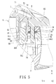
- FIG. 5 is a fragmentary schematic sectional view of FIG. 4 taken along line V-V;
- FIG. 6 is an assembled rear perspective view showing the preferred embodiment when the anchoring members are in a clamping state.
- FIG. 7 is a fragmentary schematic sectional view of FIG. 6 taken along line VII-VII.
- the preferred embodiment of a portable electronic device is shown to include a battery 6 , a main casing 3 , a cover 7 , and two anchoring members.
- the portable electronic device is an industrial personal digital assistant (PDA).
- PDA personal digital assistant
- the battery 6 has two first side surfaces 61 opposite to each other in a first direction (Y), and two second side surfaces 62 opposite to each other in a second direction (Z) perpendicular to the first direction (Y).
- the main casing 3 has first and second side surfaces 31 , 32 opposite to each other in a third direction (X) perpendicular to the first and second directions (Y, Z).
- the first and second side surfaces 31 , 32 can be respectively regarded as front and rear side surfaces.
- a display 4 and a keypad 5 are mounted on the first side surface 31 of the main casing 3 , as shown in FIG. 2 .
- the second side surface 32 of the main casing 3 is formed with a battery-receiving groove 33 for receiving the battery 6 therein, and two aligned resilient abutting tongues 36 flanking the battery-receiving groove 33 .
- the battery-receiving groove 33 is defined by two first inner sidewall surfaces 331 opposite to each other in the first direction (Y), and two second inner sidewall surfaces 332 opposite to each other in the second direction (Z).
- the second side surface 32 of the main casing 3 is further formed with the two recesses 34 disposed respectively adjacent to the first inner sidewall surfaces 331 .
- Each first inner sidewall surface 331 is formed with a via hole 35 in spatial communication with the battery-receiving groove 33 and a corresponding one of the recesses 34 (see FIG. 5 ).
- the abutting tongues 36 (only one is shown in FIG. 5 ) extend respectively into the via holes 35 in the first inner sidewall surfaces 331 in the third direction (X).
- Each abutting tongue 36 has a protrusion 361 extending toward the battery-receiving groove 33 .
- an upper one of the second inner sidewall surfaces 332 has a first surface portion 3321 perpendicular to the second side surface 32 , a second surface portion 3322 connected to and perpendicular to the first surface portion 3321 , and formed with a slot 38 disposed adjacent to the first surface portion 3321 , in spatial communication with the battery-receiving groove 33 and engaging detachably a resilient anchoring plate 63 that extends from a top one of the second side surfaces 62 of the battery 6 (see FIG. 3 ), and a third surface portion 3323 interconnecting the second surface portion 3322 and the second side surface 32 .
- the cover 7 is mounted removably on the second side surface 32 of the main casing 3 for covering the battery-receiving groove 33 .
- the cover 7 has opposite inner and outer surfaces 72 , 71 , and two through holes 73 extending from the inner surface 72 to the outer surface 71 in the third direction (X) and aligned respectively with the recesses 34 .
- the outer surface 71 is formed with two receiving grooves 74 in spatial communication with the through holes 73 , as shown in FIGS. 3 and 5 .
- the cover 7 further has two positioning blocks 75 extending from the outer surface 71 in the second direction (Z) and engaging respectively two positioning holes 37 formed in the third surface portion 3323 of the upper one of the second inner sidewall surfaces 332 of the main casing 3 .
- each anchoring member is mounted rotatably on the cover 7 , extend into the main casing 3 , and are operable so as to switch between a releasing state, where the abutting tongues 36 are spaced respectively apart from the first side surfaces 61 of the battery 6 , as shown in FIG. 5 , and a clamping state, where the abutting tongues 36 are pressed respectively against the first side surfaces 61 of the battery 6 , as shown in FIG. 7 .
- each anchoring member includes an L-shaped rod 8 , and a resilient washer 9 .
- the L-shaped rod 8 has an insertion rod portion 81 extending through a corresponding one of the through holes 73 in the cover 7 and into a corresponding of the recesses 34 in the main casing 3 , and an operating rod portion 82 connected to one end 811 of the insertion rod portion 81 and disposed rotatably on the outer surface 71 of the cover 7 .
- the insertion rod portion 81 of the L-shaped rod 8 includes a rod body 810 perpendicular to the operating rod portion 82 and having a free end 812 and opposite radially extending stopping protrusions 84 disposed adjacent to the operating rod portion 82 , and a pushing block 83 extending radially from the free end 812 and perpendicular to the rod body 810 and the operating rod portion 82 .
- the washer 9 is sleeved on the rod body 810 of the insertion rod portion 81 of the L-shaped rod 8 , and is disposed between and abuts against the stopping protrusions 84 and the inner surface 72 of the cover 7 , as best shown in FIG. 7 .
- each anchoring member is rotatable relative to the cover 7 about an axis of the rod body 810 of the insertion rod portion 81 of the L-shaped rod 8 thereof.
- the cover 7 further has two resilient extension plates 76 extending from the inner surface 72 of the cover 7 in the third direction (X) into the recesses 34 in the main casing 3 , respectively.
- Each extension plate 76 is disposed between the insertion rod portion 81 of the L-shaped rod 8 of a corresponding one of the anchoring members and a corresponding one of the abutting tongues 36 , and has a protrusion 761 extending toward the corresponding one of the abutting tongues 36 .
- the extension plates 76 of the cover 7 are pushed respectively by the pushing blocks 83 of the insertion rod portion 81 of the L-shaped rods 8 of the anchoring members to pivot toward the via holes 35 in the first inner sidewall surfaces 331 of the main casing 3 such that the abutting tongues 36 are respectively pushed and moved by the protrusions 761 of the extension plates 76 to press against the first side surfaces 61 of the battery 6 .
- the protrusion 361 of each abutting tongue 36 engages an engaging groove 611 formed in a corresponding one of the first side surfaces 61 of the battery 6 (see FIG. 7 ), and the operating rod portions 82 of the L-shaped rods 8 of the anchoring members are received respectively in the receiving grooves 74 in the outer surface 71 of the cover 7 (see FIG. 6 ).
- the extension plates 76 can be omitted.
- the abutting tongues 36 can be pushed directly and respectively by the pushing blocks 83 of the insertion rod portions 81 of the L-shaped rods 8 of the anchoring members to press against the first side surfaces 61 of the battery 6 when the anchoring members are operated in the clamping state.
- the battery 6 can be securely positioned in the housing device such that electrical connection between electrical contacts 64 of the battery 6 and electrical terminals (not shown) in the main casing 3 can be ensured. Therefore, the portable electronic device of the present invention can ensure stable power supply from the battery 6 .
Landscapes
- Engineering & Computer Science (AREA)
- Signal Processing (AREA)
- Computer Networks & Wireless Communication (AREA)
- Battery Mounting, Suspending (AREA)
Abstract
Description
Claims (6)
Priority Applications (1)
| Application Number | Priority Date | Filing Date | Title |
|---|---|---|---|
| US12/110,051 US8088507B2 (en) | 2008-04-25 | 2008-04-25 | Portable electronic device having secured battery |
Applications Claiming Priority (1)
| Application Number | Priority Date | Filing Date | Title |
|---|---|---|---|
| US12/110,051 US8088507B2 (en) | 2008-04-25 | 2008-04-25 | Portable electronic device having secured battery |
Publications (2)
| Publication Number | Publication Date |
|---|---|
| US20090270136A1 US20090270136A1 (en) | 2009-10-29 |
| US8088507B2 true US8088507B2 (en) | 2012-01-03 |
Family
ID=41215520
Family Applications (1)
| Application Number | Title | Priority Date | Filing Date |
|---|---|---|---|
| US12/110,051 Active 2030-11-03 US8088507B2 (en) | 2008-04-25 | 2008-04-25 | Portable electronic device having secured battery |
Country Status (1)
| Country | Link |
|---|---|
| US (1) | US8088507B2 (en) |
Cited By (5)
| Publication number | Priority date | Publication date | Assignee | Title |
|---|---|---|---|---|
| USD704711S1 (en) * | 2011-11-04 | 2014-05-13 | Datalogic Ip Tech S.R.L. | Portable terminal |
| USD716307S1 (en) * | 2013-05-16 | 2014-10-28 | Datalogic Ip Tech S.R.L. | Portable terminal |
| US20180062689A1 (en) * | 2016-08-29 | 2018-03-01 | Boe Technology Group Co., Ltd. | Mobile terminal and rear housing for mobile terminal |
| USD917486S1 (en) * | 2019-05-30 | 2021-04-27 | Zebra Technologies Corporation | Data capture device |
| USD922386S1 (en) * | 2018-11-19 | 2021-06-15 | Zebra Technologies Corporation | Data capture device |
Families Citing this family (11)
| Publication number | Priority date | Publication date | Assignee | Title |
|---|---|---|---|---|
| TWI392804B (en) * | 2009-02-12 | 2013-04-11 | King Slide Works Co Ltd | Housing assembly for an electrical device |
| CN201515088U (en) * | 2009-09-14 | 2010-06-23 | 深圳富泰宏精密工业有限公司 | Connector cover body structure and electronic device provided with the connector cover body structure |
| USD673955S1 (en) * | 2010-02-02 | 2013-01-08 | Psion Inc. | Handheld computer |
| USD704903S1 (en) * | 2011-07-22 | 2014-05-13 | Shenzhen Xingrisheng Industrial Co., Ltd. | Ceramic fountain |
| WO2012149806A1 (en) * | 2011-10-20 | 2012-11-08 | Huawei Technologies Co., Ltd. | Mobile terminal comprising lid unit with key device |
| USD771631S1 (en) * | 2015-06-02 | 2016-11-15 | Hand Held Products, Inc. | Mobile computer housing |
| USD829212S1 (en) * | 2016-08-01 | 2018-09-25 | Hand Held Products, Inc. | Optical scanner |
| USD883285S1 (en) * | 2017-10-13 | 2020-05-05 | Symbol Technologies, Llc | Mobile computing device |
| USD909383S1 (en) * | 2018-03-06 | 2021-02-02 | Trimble Inc. | Handheld computer device housing |
| US11437681B2 (en) * | 2019-06-28 | 2022-09-06 | Omachron Intellectual Property Inc. | Enclosure device |
| USD910636S1 (en) * | 2020-04-30 | 2021-02-16 | Trimble Inc. | Handheld computing device housing |
Citations (5)
| Publication number | Priority date | Publication date | Assignee | Title |
|---|---|---|---|---|
| US5140138A (en) * | 1989-05-16 | 1992-08-18 | Kabushiki Kaisha Toshiba | Battery operated personal terminal apparatus |
| US6455188B1 (en) * | 2000-08-23 | 2002-09-24 | Nokia Mobile Phones Ltd. | Battery lock |
| US6710576B1 (en) * | 2000-01-07 | 2004-03-23 | Motorola, Inc. | Auxiliary battery adapter for cellular telephones |
| US6730432B1 (en) * | 2002-05-23 | 2004-05-04 | Symbol Technologies, Inc. | Secure battery latch |
| US20060154136A1 (en) * | 2005-01-07 | 2006-07-13 | Fih Co.,Ltd | Battery cover latching assembly for portable electronic device |
-
2008
- 2008-04-25 US US12/110,051 patent/US8088507B2/en active Active
Patent Citations (5)
| Publication number | Priority date | Publication date | Assignee | Title |
|---|---|---|---|---|
| US5140138A (en) * | 1989-05-16 | 1992-08-18 | Kabushiki Kaisha Toshiba | Battery operated personal terminal apparatus |
| US6710576B1 (en) * | 2000-01-07 | 2004-03-23 | Motorola, Inc. | Auxiliary battery adapter for cellular telephones |
| US6455188B1 (en) * | 2000-08-23 | 2002-09-24 | Nokia Mobile Phones Ltd. | Battery lock |
| US6730432B1 (en) * | 2002-05-23 | 2004-05-04 | Symbol Technologies, Inc. | Secure battery latch |
| US20060154136A1 (en) * | 2005-01-07 | 2006-07-13 | Fih Co.,Ltd | Battery cover latching assembly for portable electronic device |
Cited By (10)
| Publication number | Priority date | Publication date | Assignee | Title |
|---|---|---|---|---|
| USD704711S1 (en) * | 2011-11-04 | 2014-05-13 | Datalogic Ip Tech S.R.L. | Portable terminal |
| USD716307S1 (en) * | 2013-05-16 | 2014-10-28 | Datalogic Ip Tech S.R.L. | Portable terminal |
| USD732534S1 (en) | 2013-05-16 | 2015-06-23 | Datalogic Ip Tech S.R.L. | Portable terminal |
| USD753119S1 (en) | 2013-05-16 | 2016-04-05 | Datalogic Ip Tech S.R.L. | Portable terminal |
| US20180062689A1 (en) * | 2016-08-29 | 2018-03-01 | Boe Technology Group Co., Ltd. | Mobile terminal and rear housing for mobile terminal |
| US10211873B2 (en) * | 2016-08-29 | 2019-02-19 | Boe Technology Group Co., Ltd. | Mobile terminal and rear housing for mobile terminal |
| USD922386S1 (en) * | 2018-11-19 | 2021-06-15 | Zebra Technologies Corporation | Data capture device |
| USD944802S1 (en) * | 2018-11-19 | 2022-03-01 | Zebra Technologies Corporation | Data capture device |
| USD1012935S1 (en) | 2018-11-19 | 2024-01-30 | Zebra Technologies Corporation | Data capture device |
| USD917486S1 (en) * | 2019-05-30 | 2021-04-27 | Zebra Technologies Corporation | Data capture device |
Also Published As
| Publication number | Publication date |
|---|---|
| US20090270136A1 (en) | 2009-10-29 |
Similar Documents
| Publication | Publication Date | Title |
|---|---|---|
| US8088507B2 (en) | Portable electronic device having secured battery | |
| US8284568B2 (en) | Key button mechanism and portable electronic device using same | |
| US8331107B2 (en) | Key button mechanism and portable electronic device using same | |
| US7264492B2 (en) | Power supply device with removable plug | |
| US8080757B2 (en) | Sliding button mechanism and portable electronic device using the same | |
| US7381059B2 (en) | Power supply device with rotatable plug | |
| US8143545B2 (en) | Sliding button mechanism | |
| CA2683352C (en) | Fixing structure for battery | |
| US20100258421A1 (en) | Control key and electronic device using the same | |
| JP2000349875A (en) | Radio communication unit, battery pack and connector | |
| US8089244B2 (en) | Electronic device | |
| US7031758B2 (en) | Mobile phone with two input modes | |
| US6385039B1 (en) | Portable computer assembly with a detachable battery module | |
| US8435663B2 (en) | Battery ejector and electronic device using the same | |
| JP2011109633A (en) | Side key module for mobile communication terminal | |
| US8334856B2 (en) | Stylus | |
| JP3122429B2 (en) | Wireless communication device, battery pack and connector | |
| US8199467B2 (en) | Battery ejector and electronic device using the same | |
| US7463911B2 (en) | Communication device | |
| US20100291809A1 (en) | Conducting mechanism for electronic device | |
| US8503158B2 (en) | Key button mechanism and portable electronic device using same | |
| KR101076510B1 (en) | Mobile terminal | |
| JP2006050758A5 (en) | ||
| CN210156950U (en) | Wireless earphone charging cabin | |
| JP2004134271A (en) | Button type battery holder and its connecting structure |
Legal Events
| Date | Code | Title | Description |
|---|---|---|---|
| AS | Assignment |
Owner name: UNIVERSAL SCIENTIFIC INDUSTRIAL CO., LTD., TAIWAN Free format text: ASSIGNMENT OF ASSIGNORS INTEREST;ASSIGNORS:SU, FEI-MING;TSENG, JIA-HAO;REEL/FRAME:020867/0817 Effective date: 20080414 |
|
| AS | Assignment |
Owner name: UNIVERSAL GLOBAL SCIENTIFIC INDUSTRIAL CO., LTD., Free format text: ASSIGNMENT OF ASSIGNORS INTEREST;ASSIGNOR:UNIVERSAL SCIENTIFIC INDUSTRIAL CO., LTD.;REEL/FRAME:025677/0814 Effective date: 20101230 Owner name: UNIVERSAL SCIENTIFIC INDUSTRIAL (SHANGHAI) CO., LT Free format text: ASSIGNMENT OF ASSIGNORS INTEREST;ASSIGNOR:UNIVERSAL SCIENTIFIC INDUSTRIAL CO., LTD.;REEL/FRAME:025677/0814 Effective date: 20101230 |
|
| STCF | Information on status: patent grant |
Free format text: PATENTED CASE |
|
| FPAY | Fee payment |
Year of fee payment: 4 |
|
| MAFP | Maintenance fee payment |
Free format text: PAYMENT OF MAINTENANCE FEE, 8TH YEAR, LARGE ENTITY (ORIGINAL EVENT CODE: M1552); ENTITY STATUS OF PATENT OWNER: LARGE ENTITY Year of fee payment: 8 |
|
| MAFP | Maintenance fee payment |
Free format text: PAYMENT OF MAINTENANCE FEE, 12TH YEAR, LARGE ENTITY (ORIGINAL EVENT CODE: M1553); ENTITY STATUS OF PATENT OWNER: LARGE ENTITY Year of fee payment: 12 |