US8083384B2 - Efficient illumination device for aircraft - Google Patents
Efficient illumination device for aircraft Download PDFInfo
- Publication number
- US8083384B2 US8083384B2 US12/364,250 US36425009A US8083384B2 US 8083384 B2 US8083384 B2 US 8083384B2 US 36425009 A US36425009 A US 36425009A US 8083384 B2 US8083384 B2 US 8083384B2
- Authority
- US
- United States
- Prior art keywords
- electromagnetic energy
- aircraft
- light source
- energy emitters
- array
- Prior art date
- Legal status (The legal status is an assumption and is not a legal conclusion. Google has not performed a legal analysis and makes no representation as to the accuracy of the status listed.)
- Expired - Fee Related, expires
Links
- 238000005286 illumination Methods 0.000 title claims abstract description 23
- 239000000758 substrate Substances 0.000 claims abstract description 55
- 230000003595 spectral effect Effects 0.000 claims description 7
- 238000012546 transfer Methods 0.000 claims description 5
- 239000000463 material Substances 0.000 description 16
- 238000000034 method Methods 0.000 description 15
- 238000001228 spectrum Methods 0.000 description 10
- 239000004020 conductor Substances 0.000 description 7
- 229910010271 silicon carbide Inorganic materials 0.000 description 7
- HBMJWWWQQXIZIP-UHFFFAOYSA-N silicon carbide Chemical compound [Si+]#[C-] HBMJWWWQQXIZIP-UHFFFAOYSA-N 0.000 description 7
- 238000004519 manufacturing process Methods 0.000 description 6
- 229910052751 metal Inorganic materials 0.000 description 6
- 239000002184 metal Substances 0.000 description 6
- 230000007480 spreading Effects 0.000 description 6
- 238000003892 spreading Methods 0.000 description 6
- 238000001429 visible spectrum Methods 0.000 description 6
- 230000007246 mechanism Effects 0.000 description 5
- 150000004767 nitrides Chemical class 0.000 description 5
- OAICVXFJPJFONN-UHFFFAOYSA-N Phosphorus Chemical compound [P] OAICVXFJPJFONN-UHFFFAOYSA-N 0.000 description 4
- 230000008569 process Effects 0.000 description 4
- 229910052594 sapphire Inorganic materials 0.000 description 4
- 239000010980 sapphire Substances 0.000 description 4
- 239000004065 semiconductor Substances 0.000 description 4
- 239000007787 solid Substances 0.000 description 4
- 229910002601 GaN Inorganic materials 0.000 description 3
- JMASRVWKEDWRBT-UHFFFAOYSA-N Gallium nitride Chemical compound [Ga]#N JMASRVWKEDWRBT-UHFFFAOYSA-N 0.000 description 3
- 239000003086 colorant Substances 0.000 description 3
- 230000005670 electromagnetic radiation Effects 0.000 description 3
- 238000001652 electrophoretic deposition Methods 0.000 description 3
- 230000004048 modification Effects 0.000 description 3
- 238000012986 modification Methods 0.000 description 3
- 238000000465 moulding Methods 0.000 description 3
- 230000003287 optical effect Effects 0.000 description 3
- 229920001296 polysiloxane Polymers 0.000 description 3
- IJGRMHOSHXDMSA-UHFFFAOYSA-N Atomic nitrogen Chemical compound N#N IJGRMHOSHXDMSA-UHFFFAOYSA-N 0.000 description 2
- 239000004642 Polyimide Substances 0.000 description 2
- 239000004954 Polyphthalamide Substances 0.000 description 2
- FTWRSWRBSVXQPI-UHFFFAOYSA-N alumanylidynearsane;gallanylidynearsane Chemical compound [As]#[Al].[As]#[Ga] FTWRSWRBSVXQPI-UHFFFAOYSA-N 0.000 description 2
- 229910052782 aluminium Inorganic materials 0.000 description 2
- RNQKDQAVIXDKAG-UHFFFAOYSA-N aluminum gallium Chemical compound [Al].[Ga] RNQKDQAVIXDKAG-UHFFFAOYSA-N 0.000 description 2
- 238000003491 array Methods 0.000 description 2
- 150000001875 compounds Chemical class 0.000 description 2
- 238000001816 cooling Methods 0.000 description 2
- 229910052802 copper Inorganic materials 0.000 description 2
- 239000010949 copper Substances 0.000 description 2
- 238000010168 coupling process Methods 0.000 description 2
- 239000008393 encapsulating agent Substances 0.000 description 2
- 229910052738 indium Inorganic materials 0.000 description 2
- 239000007788 liquid Substances 0.000 description 2
- 239000000203 mixture Substances 0.000 description 2
- 229920001721 polyimide Polymers 0.000 description 2
- 229920006375 polyphtalamide Polymers 0.000 description 2
- 230000002028 premature Effects 0.000 description 2
- 230000005855 radiation Effects 0.000 description 2
- 238000009423 ventilation Methods 0.000 description 2
- PIGFYZPCRLYGLF-UHFFFAOYSA-N Aluminum nitride Chemical compound [Al]#N PIGFYZPCRLYGLF-UHFFFAOYSA-N 0.000 description 1
- RYGMFSIKBFXOCR-UHFFFAOYSA-N Copper Chemical compound [Cu] RYGMFSIKBFXOCR-UHFFFAOYSA-N 0.000 description 1
- GYHNNYVSQQEPJS-UHFFFAOYSA-N Gallium Chemical compound [Ga] GYHNNYVSQQEPJS-UHFFFAOYSA-N 0.000 description 1
- 229910000530 Gallium indium arsenide Inorganic materials 0.000 description 1
- NIXOWILDQLNWCW-UHFFFAOYSA-N acrylic acid group Chemical group C(C=C)(=O)O NIXOWILDQLNWCW-UHFFFAOYSA-N 0.000 description 1
- XAGFODPZIPBFFR-UHFFFAOYSA-N aluminium Chemical compound [Al] XAGFODPZIPBFFR-UHFFFAOYSA-N 0.000 description 1
- AJGDITRVXRPLBY-UHFFFAOYSA-N aluminum indium Chemical compound [Al].[In] AJGDITRVXRPLBY-UHFFFAOYSA-N 0.000 description 1
- 238000000429 assembly Methods 0.000 description 1
- 230000000712 assembly Effects 0.000 description 1
- 239000000919 ceramic Substances 0.000 description 1
- 229910010293 ceramic material Inorganic materials 0.000 description 1
- 238000005229 chemical vapour deposition Methods 0.000 description 1
- PMHQVHHXPFUNSP-UHFFFAOYSA-M copper(1+);methylsulfanylmethane;bromide Chemical compound Br[Cu].CSC PMHQVHHXPFUNSP-UHFFFAOYSA-M 0.000 description 1
- 230000008878 coupling Effects 0.000 description 1
- 238000005859 coupling reaction Methods 0.000 description 1
- 239000013078 crystal Substances 0.000 description 1
- 230000003247 decreasing effect Effects 0.000 description 1
- 238000013461 design Methods 0.000 description 1
- 238000010586 diagram Methods 0.000 description 1
- 238000005401 electroluminescence Methods 0.000 description 1
- 238000000605 extraction Methods 0.000 description 1
- 238000009472 formulation Methods 0.000 description 1
- 229910052733 gallium Inorganic materials 0.000 description 1
- 230000005251 gamma ray Effects 0.000 description 1
- 229910052737 gold Inorganic materials 0.000 description 1
- APFVFJFRJDLVQX-UHFFFAOYSA-N indium atom Chemical compound [In] APFVFJFRJDLVQX-UHFFFAOYSA-N 0.000 description 1
- 238000002347 injection Methods 0.000 description 1
- 239000007924 injection Substances 0.000 description 1
- 239000012212 insulator Substances 0.000 description 1
- 230000003278 mimic effect Effects 0.000 description 1
- 229910052759 nickel Inorganic materials 0.000 description 1
- 229910052757 nitrogen Inorganic materials 0.000 description 1
- 230000006911 nucleation Effects 0.000 description 1
- 238000010899 nucleation Methods 0.000 description 1
- 230000008520 organization Effects 0.000 description 1
- TWNQGVIAIRXVLR-UHFFFAOYSA-N oxo(oxoalumanyloxy)alumane Chemical compound O=[Al]O[Al]=O TWNQGVIAIRXVLR-UHFFFAOYSA-N 0.000 description 1
- 238000004806 packaging method and process Methods 0.000 description 1
- 230000000737 periodic effect Effects 0.000 description 1
- 239000004033 plastic Substances 0.000 description 1
- 238000011160 research Methods 0.000 description 1
- 229910052710 silicon Inorganic materials 0.000 description 1
- 239000010703 silicon Substances 0.000 description 1
- 229910052709 silver Inorganic materials 0.000 description 1
Images


Classifications
-
- F—MECHANICAL ENGINEERING; LIGHTING; HEATING; WEAPONS; BLASTING
- F21—LIGHTING
- F21K—NON-ELECTRIC LIGHT SOURCES USING LUMINESCENCE; LIGHT SOURCES USING ELECTROCHEMILUMINESCENCE; LIGHT SOURCES USING CHARGES OF COMBUSTIBLE MATERIAL; LIGHT SOURCES USING SEMICONDUCTOR DEVICES AS LIGHT-GENERATING ELEMENTS; LIGHT SOURCES NOT OTHERWISE PROVIDED FOR
- F21K9/00—Light sources using semiconductor devices as light-generating elements, e.g. using light-emitting diodes [LED] or lasers
- F21K9/20—Light sources comprising attachment means
- F21K9/23—Retrofit light sources for lighting devices with a single fitting for each light source, e.g. for substitution of incandescent lamps with bayonet or threaded fittings
- F21K9/232—Retrofit light sources for lighting devices with a single fitting for each light source, e.g. for substitution of incandescent lamps with bayonet or threaded fittings specially adapted for generating an essentially omnidirectional light distribution, e.g. with a glass bulb
-
- B—PERFORMING OPERATIONS; TRANSPORTING
- B60—VEHICLES IN GENERAL
- B60Q—ARRANGEMENT OF SIGNALLING OR LIGHTING DEVICES, THE MOUNTING OR SUPPORTING THEREOF OR CIRCUITS THEREFOR, FOR VEHICLES IN GENERAL
- B60Q3/00—Arrangement of lighting devices for vehicle interiors; Lighting devices specially adapted for vehicle interiors
- B60Q3/10—Arrangement of lighting devices for vehicle interiors; Lighting devices specially adapted for vehicle interiors for dashboards
- B60Q3/14—Arrangement of lighting devices for vehicle interiors; Lighting devices specially adapted for vehicle interiors for dashboards lighting through the surface to be illuminated
-
- B—PERFORMING OPERATIONS; TRANSPORTING
- B60—VEHICLES IN GENERAL
- B60Q—ARRANGEMENT OF SIGNALLING OR LIGHTING DEVICES, THE MOUNTING OR SUPPORTING THEREOF OR CIRCUITS THEREFOR, FOR VEHICLES IN GENERAL
- B60Q3/00—Arrangement of lighting devices for vehicle interiors; Lighting devices specially adapted for vehicle interiors
- B60Q3/60—Arrangement of lighting devices for vehicle interiors; Lighting devices specially adapted for vehicle interiors characterised by optical aspects
- B60Q3/68—Arrangement of lighting devices for vehicle interiors; Lighting devices specially adapted for vehicle interiors characterised by optical aspects using ultraviolet light
-
- F—MECHANICAL ENGINEERING; LIGHTING; HEATING; WEAPONS; BLASTING
- F21—LIGHTING
- F21Y—INDEXING SCHEME ASSOCIATED WITH SUBCLASSES F21K, F21L, F21S and F21V, RELATING TO THE FORM OR THE KIND OF THE LIGHT SOURCES OR OF THE COLOUR OF THE LIGHT EMITTED
- F21Y2113/00—Combination of light sources
- F21Y2113/10—Combination of light sources of different colours
- F21Y2113/13—Combination of light sources of different colours comprising an assembly of point-like light sources
-
- F—MECHANICAL ENGINEERING; LIGHTING; HEATING; WEAPONS; BLASTING
- F21—LIGHTING
- F21Y—INDEXING SCHEME ASSOCIATED WITH SUBCLASSES F21K, F21L, F21S and F21V, RELATING TO THE FORM OR THE KIND OF THE LIGHT SOURCES OR OF THE COLOUR OF THE LIGHT EMITTED
- F21Y2115/00—Light-generating elements of semiconductor light sources
- F21Y2115/10—Light-emitting diodes [LED]
Definitions
- Aircraft cockpit display panel illumination systems are designed around the output of a filament based incandescent light source (incandescent filament lamps), which is measured in mean spherical candle power (MSCP) radiating light in a spherical emission pattern.
- the incandescent lamps operate from standard 14 VDC or 28 VDC aircraft electrical power systems.
- Current aircraft cockpit panel illumination systems were designed for incandescent filament lamps, which require little or no thermal transfer.
- An LED lamp is a type of solid state lighting that uses light-emitting diodes (LEDs) as the source of light, rather than electrical filaments.
- LEDs light-emitting diodes
- a typical LED produces non-uniform radiation patterns primarily due to packaging constraints. Accordingly, typical LED lamps produce unsatisfactory illumination appearance.
- a typical miniature LED lamp incorporates only a single LED, which has a forward voltage drop of anywhere from about 2 VDC to about 3.5 VDC.
- a basic LED lamp used in an aircraft cockpit display panel illumination system requires a dropping resistor in series with the LED to offset the 14 VDC or 28 VDC aircraft electrical power operating system.
- the product of excess voltage dropped across the resistor and current through the resistor manifests itself as heat, which must be dissipated.
- the dropping resistor is formed integrally with the LED lamp assembly. For this reason, excess heat produced by the dropping resistor can eventually lead to premature failure of the LED lamp assembly. In order to increase the life and reliability of the LED lamp, the heat must be drawn away from the LED.
- an aircraft light source comprises a first substrate having a first side and a second side.
- An array of electromagnetic energy emitters is disposed on the first side.
- the electromagnetic energy emitters are connected in series and the electromagnetic energy emitters are configured to radiate electromagnetic energy at one or more than one predetermined wavelength.
- the second side of the first substrate is configured to connect to a second substrate.
- a second substrate is connected to the first substrate.
- the second substrate comprises a first side, a second side, a first end, and a second end.
- the first and second sides are configured to receive one or more electrical components.
- the first end is configured to electrically couple to the array of electromagnetic energy emitters and the second end is configured to electrically couple to an aircraft electrical power system.
- the aircraft light source comprises a housing having a cylindrical portion and a base portion.
- the cylindrical portion has a first end configured to couple to a lens and a second end configured to couple to an electric socket suitable for an incandescent lamp in an aircraft illumination system.
- the cylindrical portion defines an opening to receive the array of electromagnetic energy emitters and the first and second substrates therein.
- the base portion is adapted and configured to electrically couple to an electric socket suitable for an incandescent lamp in an aircraft illumination system.
- FIG. 1 is an exploded perspective view of one embodiment of a light source suitable for an aircraft cockpit display panel illumination system.
- FIG. 2 is an exploded perspective view of one embodiment of the light source shown in FIG. 1 .
- FIG. 3 is an exploded perspective view of one embodiment of the light source shown in FIG. 1 .
- FIG. 4 is an exploded side view of one embodiment of the light source shown in FIG. 1 .
- FIG. 5 is an exploded side view of one embodiment of the light source shown in FIG. 1 .
- FIG. 6 is an exploded side view of one embodiment of the light source shown in FIG. 1 .
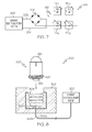
- FIG. 7 is a schematic view of one embodiment of the light emitting element of the light source shown in FIG. 1 coupled to an aircraft electrical power system.
- FIG. 8 illustrates a cross-sectional view of an aircraft cockpit display system configured to receive embodiment of a light source.
- FIG. 9 illustrates a partial cross-sectional view of an aircraft cockpit display system configured to receive one embodiment of an aircraft light source assembly shown in a first position.
- FIG. 10 illustrates a partial cross-sectional view of the aircraft cockpit display system shown in FIG. 9 with one embodiment of the light source assembly shown in a second snapped-in position.
- first, second, and so on may be used herein to describe various elements, components, regions, layers, and/or sections, these elements, components, regions, layers and/or sections should not be limited by these terms. These terms are only used to distinguish one element, component, region, layer, or section from another region, layer or section. Thus, a first element, component, region, layer, or section discussed below could be termed a second element, component, region, layer, or section without limiting the scope of the appended claims.
- FIGS. 1-6 illustrate one embodiment of a light source 100 suitable for an aircraft cockpit display panel illumination system.
- the light source 100 comprises a first substrate 102 having a first side 104 and a second side 106 .
- An array 108 of electromagnetic energy emitters 110 1-n is disposed on the first side 104 of the first substrate 102 in any predetermined arrangement.
- the array 108 comprises four electromagnetic energy emitters 110 1-4 connected in series.
- the electromagnetic energy emitters 110 1-4 are configured to radiate electromagnetic energy at one or more than one predetermined wavelength.
- each one of the electromagnetic energy emitters 110 1-4 is configured to radiate electromagnetic energy at a different wavelength or at one or more than one wavelength.
- At least one of the electromagnetic energy emitters 110 1-4 comprises at least one light emitting element such as one or more than one LED, for example.
- Elements of the electromagnetic energy emitters 110 1-4 are electrically interconnected by a network of electrical conductors and are coupled to aircraft electrical power system 200 ( FIG. 7 ) to energize the electromagnetic energy emitters 110 1-4 .
- the light source 100 produces a specific spectral output, which is suitable for aircraft cockpit display panel illumination systems designed around the output of an incandescent filament lamp.
- the specific spectral output may be suitable for use in existing incandescent filament lamp systems to illuminate aircraft cockpit displays, instrument panels, avionics, switch panels, and aircraft interiors. Electrical connections to the electromagnetic energy emitters 110 1-4 may be made through conventional electrical contacts.
- each of the four electromagnetic energy emitters 110 1-4 are arranged in one array.
- each of the four electromagnetic energy emitters 110 1-4 may be configured to radiate electromagnetic radiation at the same wavelength or at different wavelengths when energized by an electrical power source, such as an aircraft electrical power system 200 ( FIG. 7 ).
- Each of the electromagnetic energy emitters 110 1-4 may comprise LEDs, vertical cavity surface emitting lasers (VCSELs), or other semiconductor devices configured to radiate electromagnetic energy at one or more than one predetermined wavelength.
- the electromagnetic energy emitters 110 1-4 may comprise one or more LEDs configured to emit light at predetermined visible wavelengths.
- Each of the electromagnetic energy emitters 110 1-4 may comprise one or more LEDs.
- each of the electromagnetic energy emitters 110 1-4 comprises a corresponding LED.
- the first and second electromagnetic energy emitters 110 1 , 110 2 may be configured to radiate the red light in the wavelength range of about 620 nm to about 750 nm and the third and fourth electromagnetic energy emitters 110 3 , 110 4 may be configured to radiate blue light in the wavelength range of about 450 nm to about 495 nm.
- the electromagnetic energy emitters 110 1-4 may be configured to radiate light at any suitable wavelength.
- the light source 100 may be configured to radiate light at a single monochromatic wavelength. It will be appreciated by those skilled in the art that the light source 100 may comprise one or more light emitting elements that, when energized by an electrical power source, such as an aircraft electrical power system 200 ( FIG. 7 ), may be configured to radiate electromagnetic energy in the visible spectrum as well as the invisible spectrum.
- the visible spectrum sometimes referred to as the optical spectrum or luminous spectrum, is that portion of the electromagnetic spectrum that is visible to (e.g., can be detected by) the human eye and may referred to as visible light or simply light.
- a typical human eye will respond to wavelengths in air from about 380 nm to about 750 nm.
- the visible spectrum is continuous and without clear boundaries between one color and the next. The following ranges may be used as an approximation of color wavelength:
- Red about 620 nm to about 750 nm.
- the invisible spectrum is that portion of the electromagnetic spectrum lies below and above the visible spectrum (e.g., below about 380 nm and above about 750 nm).
- the invisible spectrum is not detectable by the human eye.
- Wavelengths greater than about 750 nm are longer than the red visible spectrum and they become invisible infrared, microwave, and radio electromagnetic radiation.
- Wavelengths less than about 380 nm are shorter than the violet spectrum and they become invisible ultra-violet, x-ray, and gamma ray electromagnetic radiation.
- multiple light sources 100 configured to radiate light in the visible spectrum may be disposed in a predetermined array or arrangement.
- the light sources 100 When the light sources 100 are energized by the aircraft electrical power system 200 ( FIG. 7 ), the light sources 100 produce a specific uniform predetermined spectral output suitable for use in existing incandescent filament lamp systems for illuminating aircraft cockpit displays, instrument panels, avionics, switch panels, and aircraft interiors.
- the light source 100 comprises a second substrate 112 , which comprises a first side 114 , a second side 116 , a first end 118 , and a second end 120 .
- the first and second sides 114 , 116 are configured to receive one or more electrical components 122 .
- the first end 118 of the second substrate 112 is connected to the second side 106 of the first substrate 102 .
- the second substrate 112 is connected substantially perpendicularly to the first substrate 102 .
- the first end 118 is configured to electrically couple to the array 108 of the electromagnetic energy emitters 110 1-4 .
- the second end 120 is configured to electrically couple to the aircraft electrical power system 200 ( FIG. 7 ).
- a resistor 142 is disposed on the second substrate 112 and is coupled in series to the array 108 of the electromagnetic energy emitters 110 .
- a rectifier 144 is disposed on the second substrate 112 to convert alternating current received from the aircraft electrical power system 200 to direct current suitable for powering the array 108 of the electromagnetic energy emitters 110 .
- the second substrate 112 may be T-shaped.
- the first and second substrate 102 , 112 may be formed in any suitable shape or size and configured to be removably or fixedly attached to a housing 124 .
- the first and second substrate 102 , 112 may be formed as a unitary substrate.
- the first and second substrate 102 , 112 can be made of many different structures and materials such as a printed circuit board (PCB), standard FR-4 PCB, ceramic, a metal core printed circuit board (MCPCB), or any other suitable type of printed circuit board materials.
- Other suitable materials include, without limitation, ceramic materials such as aluminum oxide, aluminum nitride or organic insulators like polyimide (PI), and polyphthalamide (PPA) laminated with thermally and electrically conductive materials such as copper or other similar materials.
- the first and second substrate 102 , 112 may comprise sapphire or silicon, or any other suitable material, such as T-Clad thermal clad insulated substrate material, available from The Bergquist Company of Chanhassen, Minn.
- the housing 124 has a cylindrical portion 126 and a base 128 portion.
- the cylindrical portion 126 has a first end 129 configured to couple to a lens 130 (e.g., ball lens, lens cap, optical cap) and a second end 132 configured to couple to an electric socket suitable for an incandescent lamp in an avionics cockpit display system.
- a lens 130 e.g., ball lens, lens cap, optical cap
- the cylindrical portion 126 defines an opening 134 to receive the array 108 of the electromagnetic energy emitters 110 and the first and second substrates 102 , 112 , therein.
- the base 128 is adapted and configured to electrically couple to an electric socket suitable for an incandescent filament lamp for illuminating an aircraft cockpit display, instrument panel, avionics, switch panels, and aircraft interiors, for example.
- the base 128 acts as the electrical return terminal.
- An electrical contact 138 is formed on the base 128 of the housing 124 .
- the electrical contact 138 is the power receiving portion of the light source 100 .
- the base 128 and the electrical contact 138 portion are adapted to couple to the aircraft electrical power system 200 ( FIGS. 7 and 8 ).
- the base e.g., base 128 ′ as described with reference to FIG.
- the base 128 may provide an electrical contact surface for coupling to an aircraft cockpit display, instrument panel, avionics, switch panels, and aircraft interiors, for example, as described with reference to FIGS. 9 and 10 below.
- the lens 130 may be produced from acrylic or any other suitable optically transmissive plastic.
- the lens 130 may be configured to couple to the first end 129 of the cylindrical portion 126 of the housing 124 .
- the lens 130 comprises a plurality of projecting members 136 and the first end 129 of the cylindrical portion 126 of the housing 124 comprises a plurality of slots 146 to receive the respective projecting members 136 .
- the lens 130 may be coated, injected molded, or impregnated with one or more phosphors to absorb at least some of the energy emitted by the electromagnetic energy emitters 110 1-4 .
- the energy output through the lens 130 is a combination of energy emitted by the electromagnetic energy emitters 110 and phosphor light.
- the lens 130 can be coated using many different methods such as, for example, electrophoretic deposition (EPD).
- EPD electrophoretic deposition
- a mixture of phosphor and silicone can be introduced (e.g., potted) into the opening 148 defined by the concave portion 150 of the lens cap 130 , as best seen in FIG. 3 .
- the light source 100 can be used as an efficient drop-in replacement for conventional miniature incandescent filament lamps for illuminating aircraft cockpit displays, instrument panels, avionics, switch panels, and aircraft interiors.
- Typical incandescent filament lamps used in aircraft applications operate from standard 14 VDC or 28 VDC aircraft electrical power systems.
- replacing the incandescent filament lamp with an LED lamp comprising a single LED is not efficient because of the excess heat that must be dissipated by the LED lamp assembly.
- a single blue wavelength LED has a typical forward bias voltage of about 3.5 VDC. To achieve sufficient radiant power, the blue wavelength LED should be driven at a current I 1 of about 30 mA.
- the current limiting resistor 142 connected in series with the blue wavelength LED will drop 24.5 VDC.
- FIG. 7 is a schematic diagram showing the four LED 110 1-4 array 108 portion of the light source 100 coupled to an aircraft electrical power system 200 .
- the aircraft electrical power system 200 may be configured to supply a direct current (DC) or an alternating current (AC) at output terminals 202 , 204 .
- the rectifier 144 may be connected to the output terminals 202 , 204 to supply DC voltage to the four LED 110 1-4 array 108 regardless of whether the aircraft electrical power system 200 is a DC or AC source.
- the rectifier 144 can be connected between the aircraft electrical power system 200 and the four LED 110 1-4 array 108 to supply a DC voltage suitable for operating the light source 100 .
- the aircraft electrical power system 200 is representative of one of many ways to supply electrical power to the light source 100 .
- the aircraft electrical power system 200 may be coupled to a bank of batteries.
- the LEDs 110 1-4 may be interconnected and arranged in one or more arrays. As shown, the four LEDs 110 1-4 are connected in series and are connected in series with the current limiting resistor 142 . As shown in FIG. 7 , the array 108 is coupled to a 28 VDC aircraft electrical power system 200 .
- the forward bias voltage drop Vf 1-4 across each LED 110 1-4 is about 3.5 VDC, thus the total bias voltage drop across all four LEDs 110 1-4 is about 14 VDC, or the sum of the bias voltage drops Vf 1-4 for each LED 110 1-4 .
- the array 108 of series connected LEDs 110 1-4 produces sufficient radiant power while consuming much less electrical power and, as a result, dissipating much less heat. Because conventional incandescent filament lamps assemblies in aircraft cockpit displays, instrument panels, avionics, switch panels, and aircraft interiors generally are not thermally conductive, the array 108 provides a suitable efficient light source 100 for avionic cockpit displays, instrument panels, switch panels, and aircraft interiors.
- the array 108 can be scalable to an N ⁇ M array (where N and M are any positive integers) of electromagnetic energy emitters (e.g., LEDs). The number of electromagnetic energy emitters in the array may be limited by the available power supply, e.g., 28 VDC for the aircraft electrical power system 200 .
- the LEDs 110 1-4 used in the light source 100 are highly efficient semiconductor photon sources that can radiate light in the visible as well as the invisible spectrum. They are typically forward-biased p-n junctions fabricated from a semiconductor material that emits light via injection electroluminescence. The small size, high efficiency, high reliability, and compatibility with electronic systems make the LEDs 110 1-4 very useful for the aircraft light source 100 application. Any suitable combination of LEDs may be employed. For example, any combination of LEDs that can radiate visible light in a range of colors or LEDs that can radiate infrared and ultraviolet light may be employed in the light source 100 .
- the light source 100 may comprise multiple LEDs arranged in various configurations or arrays to achieve luminous outputs at various wavelengths. Various spectral responses may be produced based on the intensity of the light emitted by the individual LED 110 1-4 elements.
- the LEDs 110 1-4 are laid out on a surface of the first side 104 of the first substrate 102 in the array 108 .
- the array 108 may take nearly any shape.
- the necessary electrical connections to power the LED 110 1-4 array 108 are provided to input and output connections, which also may be located on the first side 104 of the fist substrate 102 .
- the LED 110 1-4 array 108 can be arranged and interconnected in various ways.
- the LED 110 1-4 array 108 can be soldered, wire-bonded, epoxied, or can be interconnected using a connector, for example.
- the light source 100 may comprise many different types of solid state electromagnetic energy emitters 110 1-n , even though the embodiments have been described in relation to LEDs, provided that the solid state electromagnetic energy emitters 110 1-n emit light at a wavelength suitable for use in existing incandescent filament lamps to illuminate aircraft cockpit displays, instrument panels, avionics, switch panels, and aircraft interiors. It is also to be understood that different colors of LEDs can be used in a single array with a suitable mixer to generate the desired output color of light. For example, red emitting LEDs can be combined with green and blue emitting LEDs so that the array emits white light.
- the embodiments discussed herein may be employed in many different aircraft lighting applications and the discussion of the embodiments herein should not be construed as limiting to a particular embodiment or similar embodiments.
- the optical design and color temperature formulation of the light source 100 may be selected to produce light emissions that mimic incandescent filament lamp performance.
- the housing 124 may be selected to enable the light source 100 to be used as a drop-in replacement for an incandescent filament lamp.
- the electromagnetic energy source comprises a high efficiency LED lamp assembly to replace the incandescent filament based (white light) lamps in aircraft illumination and indication applications.
- the structures of the LEDs 110 1-4 and their fabrication and operation are generally known in the art and are only briefly discussed herein.
- the LED 110 1-4 layers can be fabricated using known processes with a suitable process being fabrication using metal organic chemical vapor deposition (MOCVD).
- MOCVD metal organic chemical vapor deposition
- the LED 110 1-4 layers generally comprise an active layer/region sandwiched between first and second oppositely doped epitaxial layers all of which are formed successively on a growth substrate.
- the LEDs 110 1-4 can be formed on a wafer and then singulated for mounting on the substrate 102 . It is understood that the growth substrate can remain as part of the final singulated LED 110 1-4 or the growth substrate can be fully or partially removed.
- the active region can comprise single quantum well (SQW), multiple quantum well (MQW), double heterostructure, or super lattice structures.
- SQW single quantum well
- MQW multiple quantum well
- the active region and doped layers may be fabricated from different material systems, with preferred material systems being Group-III nitride based material systems.
- Group-III nitrides refer to those semiconductor compounds formed between nitrogen and the elements in the Group III of the periodic table, usually aluminum (Al), gallium (Ga), and indium (In).
- the term also refers to ternary and quaternary compounds such as aluminum gallium nitride (AlGaN) and aluminum indium gallium nitride (AlInGaN).
- the doped layers are gallium nitride (GaN) and the active region is InGaN.
- the doped layers may be AlGaN, aluminum gallium arsenide (AlGaAs) or aluminum gallium indium arsenide phosphide (AlGaInAsP).
- the growth substrate can be made of many materials such at sapphire, silicon carbide, aluminum nitride (AlN), GaN, with a suitable substrate being a 4H polytype of silicon carbide, although other silicon carbide polytypes can also be used including 3C, 6H and 15R polytypes.
- Silicon carbide has certain advantages, such as a closer crystal lattice match to Group III nitrides than sapphire and results in Group III nitride films of higher quality. Silicon carbide also has a very high thermal conductivity so that the total output power of Group-III nitride devices on silicon carbide are typically not limited by the thermal dissipation of the substrate 102 (as may be the case with some devices formed on sapphire).
- SiC substrates are available from Cree Research, Inc., of Durham, N.C. and methods for producing them are set forth in the scientific literature as well as in a U.S. Pat. Nos. Re. 34,861; 4,946,547; and 5,200,022.
- the LEDs 110 1-4 also may comprise a conductive current spreading structure and the one or more wire bond pads on their top surface, both of which are made of a conductive material and can be deposited using known methods. Some materials that can be used for these elements include Au, Cu, Ni, In, Al, Ag or combinations thereof and conducting oxides and transparent conducting oxides.
- the current spreading structure generally comprises conductive fingers arranged in a grid on the LEDs 110 1-4 with the fingers spaced to enhance current spreading from the pads into the top surface of the LEDs 110 1-4 . In operation, an electrical signal may be applied to the bond pads through wire bonds and the electrical signal spreads through the fingers of the current spreading structure and the top surface into the LEDs 110 1-4 . Current spreading structures are often used in LEDs where the top surface is p-type, but can also be used for n-type materials.
- the LEDs 110 1-4 may be coated with one or more phosphors with the phosphors absorbing at least some of the LED 110 1-4 light and emitting a different wavelength of light such that the light source 100 emits a combination of light from the LED 110 1-4 and the phosphor. In one embodiment, the LED 110 1-4 emits a combination of LED and phosphor light.
- the LEDs 110 1-4 can be coated using many different methods. Alternatively, the LEDs 110 1-4 can be coated using other methods such as the previously discussed EPD method. It is understood that one LED may comprise multiple LEDs of different colors, one or more of which may be white emitting.
- an encapsulant may be formed over the LEDs 110 1-4 by molding over each of the LEDs 110 1-4 and many different molding methods can be used. In one embodiment a molding process may be used to simultaneously form lenses over the LEDs 110 1-4 .
- a suitable encapsulant material may be liquid curable silicone. The liquid silicone can be poured over the LEDs 110 1-4 and can then be cured using known curing processes.
- FIG. 8 illustrates a cross-sectional view of an aircraft cockpit display system 300 configured to receive one embodiment of an aircraft light source 100 ′.
- the internal components of the light source 100 ′ were previously discussed in FIGS. 1-7 with the exception being that base 128 ′ is threaded.
- the aircraft cockpit display system 300 comprises a panel 302 .
- the panel 302 is representative of aircraft cockpit displays, instrument panels, avionics, switch panels, and aircraft interiors illuminated by light sources.
- a metal electric socket 304 disposed within the panel 302 and is adapted and configured to receive conventional miniature incandescent filament lamps to illuminate the panel 302 , e.g., aircraft cockpit displays, instrument panels, avionics, switch panels, aircraft interiors.
- the light source 100 ′ is configured as an efficient drop-in replacement for conventional miniature incandescent filament lamps to illuminate the panel 302 .
- the male-threaded base 128 ′ of the light source 100 ′ is configured to be received within the female-threaded socket 304 , which is the electrical return terminal.
- the electrical contact 138 the power receiving portion of the light source 100 ′, is configured to couple to a metal contact spring 306 , which is the power receiving input terminal.
- the electric socket 304 and the contact spring 306 are coupled to the aircraft electrical power system 200 through electrical conductors 308 a and 308 b .
- the base 128 ′ of the light source 100 ′ may be configured in any suitable manner to match particular aircraft cockpit display systems.
- Other configurations, such as snap-in or twist-in light source-to-socket coupling techniques are within the scope of this specification. Accordingly, the embodiments are not limited in this context.
- the light source 100 ′ comprises an array 108 of electromagnetic energy emitters 110 1-n and produces a uniform radiation pattern suitable for replacement of conventional incandescent filament based lamps.
- the power dissipation of the array 108 of electromagnetic energy emitters 110 1-n is low such that excess heat is not produced within the socket 304 and/or the panel 302 and does not require ventilation or cooling for drawing excess heat away form the light source 100 ′.
- the light source 100 ′ may be coupled to the aircraft electrical power system 200 . Accordingly, the light source 100 ′ is a suitable drop-in replacement for conventional incandescent filament based lamps in aircraft panel 302 systems and does not suffer for the power dissipation limitations of conventional single LED replacement lamps.
- FIGS. 9 and 10 illustrates a partial cross-sectional view of an aircraft cockpit display system 400 configured to receive one embodiment of an aircraft light source assembly 450 .
- FIG. 9 illustrates the aircraft cockpit display system 400 with the one embodiment of the light source assembly 450 shown in a first position.
- FIG. 10 illustrates the aircraft cockpit display system 400 with one embodiment of the light source assembly 450 shown in a second snapped-in position.
- the light source assembly 450 is movable between the first position and the second position by applying a pushing force 412 against an outer surface of an optically transparent member 410 of the light source assembly 450 .
- the light source assembly 450 comprises the light source 100 , previously discussed in FIGS.
- the aircraft cockpit display system 400 comprises a panel 402 configured to house the aircraft light source assembly 450 .
- the panel 402 is representative of aircraft cockpit displays, instrument panels, avionics, switch panels, and aircraft interiors illuminated by light sources.
- the electrically insulative housing 406 is disposed within the panel 402 and is adapted and configured to receive conventional miniature incandescent filament lamps to illuminate the panel 402 , e.g., aircraft cockpit displays, instrument panels, avionics, switch panels, aircraft interiors.
- light generated by the array 108 of electromagnetic energy emitters 110 1-n exits the lens 130 portion of the light source 100 and is transmitted through the optically transparent member 410 .
- the sleeve 404 is slidably disposed within the housing 406 and is adapted and configured to receive the light source 100 in an opening defined therein. The sleeve 404 is attached to the optically transparent member 410 .
- the light source 100 is configured as an efficient drop-in replacement for conventional miniature incandescent filament lamps to illuminate the panel 402 .
- the plunger switch mechanism 408 is slidably disposed within the housing 406 .
- the plunger switch mechanism 408 is spring loaded and engages the electrical contact 138 , which is the power receiving portion of the light source 100 .
- the sleeve 404 and the optically transparent member 410 form a lighted push-button assembly.
- the plunger switch mechanism 408 can be actuated and deactuated by applying the pushing force 412 against the optically transparent member 410 .
- the light source 100 is coupled to the aircraft electrical power system 200 through electrical conductors 308 a and 308 b .
- the base 128 of the light source 100 is configured to contact electrically conductive surfaces of the sleeve 404 and forms the electrical return terminal.
- the plunger switch mechanism 408 is coupled to the electrical contact 138 and the aircraft electrical power system 200 through the electrical conductor 308 b .
- the base 128 is coupled to the aircraft electrical power system 200 through the electrical conductor 308 a.
Landscapes
- Engineering & Computer Science (AREA)
- Mechanical Engineering (AREA)
- Physics & Mathematics (AREA)
- Microelectronics & Electronic Packaging (AREA)
- Optics & Photonics (AREA)
- General Engineering & Computer Science (AREA)
- Arrangement Of Elements, Cooling, Sealing, Or The Like Of Lighting Devices (AREA)
- Non-Portable Lighting Devices Or Systems Thereof (AREA)
Abstract
Description
24.5 VDC=28 VDC−3.5 VDC
735 mW=24.5 VDC*30 mA
140 mW=14 VDC*10 mA
Claims (23)
Priority Applications (2)
| Application Number | Priority Date | Filing Date | Title |
|---|---|---|---|
| US12/364,250 US8083384B2 (en) | 2009-02-02 | 2009-02-02 | Efficient illumination device for aircraft |
| PCT/US2010/020032 WO2010088003A1 (en) | 2009-02-02 | 2010-01-04 | Efficient illumination device for aircraft |
Applications Claiming Priority (1)
| Application Number | Priority Date | Filing Date | Title |
|---|---|---|---|
| US12/364,250 US8083384B2 (en) | 2009-02-02 | 2009-02-02 | Efficient illumination device for aircraft |
Publications (2)
| Publication Number | Publication Date |
|---|---|
| US20100195338A1 US20100195338A1 (en) | 2010-08-05 |
| US8083384B2 true US8083384B2 (en) | 2011-12-27 |
Family
ID=41800722
Family Applications (1)
| Application Number | Title | Priority Date | Filing Date |
|---|---|---|---|
| US12/364,250 Expired - Fee Related US8083384B2 (en) | 2009-02-02 | 2009-02-02 | Efficient illumination device for aircraft |
Country Status (2)
| Country | Link |
|---|---|
| US (1) | US8083384B2 (en) |
| WO (1) | WO2010088003A1 (en) |
Cited By (1)
| Publication number | Priority date | Publication date | Assignee | Title |
|---|---|---|---|---|
| US8534901B2 (en) | 2010-09-13 | 2013-09-17 | Teledyne Reynolds, Inc. | Collimating waveguide apparatus and method |
Families Citing this family (4)
| Publication number | Priority date | Publication date | Assignee | Title |
|---|---|---|---|---|
| JP5268166B2 (en) * | 2010-09-21 | 2013-08-21 | 株式会社スズデン | Lighting device |
| US10274183B2 (en) | 2010-11-15 | 2019-04-30 | Cree, Inc. | Lighting fixture |
| FR2978813B1 (en) * | 2011-08-04 | 2015-04-24 | Ledpower | LED LAMP DEVICE AND AUTOMATED METHOD FOR MANUFACTURING THE SAME |
| US9644799B2 (en) * | 2013-03-13 | 2017-05-09 | Smartbotics Inc. | LED light bulb construction and manufacture |
Citations (6)
| Publication number | Priority date | Publication date | Assignee | Title |
|---|---|---|---|---|
| EP0107480A2 (en) | 1982-10-21 | 1984-05-02 | Idec Izumi Corporation | Light emission diode lamp and method of producing it |
| EP0557775A1 (en) | 1992-02-28 | 1993-09-01 | EBT Licht-Technik GmbH | Arrangement with a rectifier connectable to an A.C.voltage |
| US6886963B2 (en) * | 2002-06-21 | 2005-05-03 | Pervaiz Lodhie | LED light bulb for use in an illuminated aircraft sign |
| US20070007898A1 (en) | 2003-09-09 | 2007-01-11 | Koninklijke Philips Electronics N.V. | Integrated lamp with feedback and wireless control |
| WO2008037940A1 (en) | 2006-09-26 | 2008-04-03 | Ghollam Tahmosybayat | Lamp assembly |
| US7758223B2 (en) * | 2005-04-08 | 2010-07-20 | Toshiba Lighting & Technology Corporation | Lamp having outer shell to radiate heat of light source |
Family Cites Families (3)
| Publication number | Priority date | Publication date | Assignee | Title |
|---|---|---|---|---|
| US4866005A (en) | 1987-10-26 | 1989-09-12 | North Carolina State University | Sublimation of silicon carbide to produce large, device quality single crystals of silicon carbide |
| US4946547A (en) | 1989-10-13 | 1990-08-07 | Cree Research, Inc. | Method of preparing silicon carbide surfaces for crystal growth |
| US5200022A (en) | 1990-10-03 | 1993-04-06 | Cree Research, Inc. | Method of improving mechanically prepared substrate surfaces of alpha silicon carbide for deposition of beta silicon carbide thereon and resulting product |
-
2009
- 2009-02-02 US US12/364,250 patent/US8083384B2/en not_active Expired - Fee Related
-
2010
- 2010-01-04 WO PCT/US2010/020032 patent/WO2010088003A1/en active Application Filing
Patent Citations (7)
| Publication number | Priority date | Publication date | Assignee | Title |
|---|---|---|---|---|
| EP0107480A2 (en) | 1982-10-21 | 1984-05-02 | Idec Izumi Corporation | Light emission diode lamp and method of producing it |
| EP0557775A1 (en) | 1992-02-28 | 1993-09-01 | EBT Licht-Technik GmbH | Arrangement with a rectifier connectable to an A.C.voltage |
| US6886963B2 (en) * | 2002-06-21 | 2005-05-03 | Pervaiz Lodhie | LED light bulb for use in an illuminated aircraft sign |
| US20070007898A1 (en) | 2003-09-09 | 2007-01-11 | Koninklijke Philips Electronics N.V. | Integrated lamp with feedback and wireless control |
| US7521872B2 (en) * | 2003-09-09 | 2009-04-21 | Koninklijke Philips Electronics, N.V. | Integrated lamp with feedback and wireless control |
| US7758223B2 (en) * | 2005-04-08 | 2010-07-20 | Toshiba Lighting & Technology Corporation | Lamp having outer shell to radiate heat of light source |
| WO2008037940A1 (en) | 2006-09-26 | 2008-04-03 | Ghollam Tahmosybayat | Lamp assembly |
Non-Patent Citations (2)
| Title |
|---|
| International Search Report mailed Mar. 29, 2010 for Application No. PCT/US2010/020032, 5 pages. |
| Written Opinion of the International Searching Authority for Application No. PCT/US2010/020032, 6 pages. |
Cited By (1)
| Publication number | Priority date | Publication date | Assignee | Title |
|---|---|---|---|---|
| US8534901B2 (en) | 2010-09-13 | 2013-09-17 | Teledyne Reynolds, Inc. | Collimating waveguide apparatus and method |
Also Published As
| Publication number | Publication date |
|---|---|
| WO2010088003A1 (en) | 2010-08-05 |
| US20100195338A1 (en) | 2010-08-05 |
Similar Documents
| Publication | Publication Date | Title |
|---|---|---|
| US10679973B2 (en) | Multiple pixel surface mount device package | |
| US10347804B2 (en) | Light source package and display device including the same | |
| US10842016B2 (en) | Compact optically efficient solid state light source with integrated thermal management | |
| US20150022114A1 (en) | Tubular light-emitting apparatus | |
| US9097393B2 (en) | LED based lamp assembly | |
| US9468066B2 (en) | Photo sensor-integrated tubular light emitting apparatus and lighting system using the same | |
| US20110037083A1 (en) | Led package with contrasting face | |
| US20160215939A1 (en) | Wide angle based indoor lighting lamp | |
| KR20150002361A (en) | Semiconductor light emitting device and method for manufacturing method for light source module | |
| US9698304B2 (en) | Lighting system | |
| US8083384B2 (en) | Efficient illumination device for aircraft | |
| EP2315283B1 (en) | Light emitting device package, lighting module and lighting unit | |
| US20150292682A1 (en) | Lighting apparatus | |
| US20150233551A1 (en) | Method of manufacturing light source module and method of manufacturing lighting device | |
| WO2018132962A1 (en) | Multiple led light source lens design in an integrated package | |
| KR101423387B1 (en) | Coated diffuser cap for led illumination device | |
| CN108321149B (en) | Light emitting diode package and light emitting diode display | |
| KR20190121945A (en) | Lighting device | |
| KR101142961B1 (en) | Led lamp mounting a led having an array of light emitting cells coupled in series | |
| KR20150083248A (en) | Package for light emitting device | |
| KR20180085223A (en) | Light device | |
| KR102007407B1 (en) | Light emitting device and Light emitting device package | |
| KR20160073617A (en) | Lighting device | |
| KR20160066229A (en) | Lighting device |
Legal Events
| Date | Code | Title | Description |
|---|---|---|---|
| AS | Assignment |
Owner name: TELEDYNE LIGHTING AND DISPLAY PRODUCTS, INC., CALI Free format text: ASSIGNMENT OF ASSIGNORS INTEREST;ASSIGNORS:PANAGOTACOS, GEORGE;CHEN, VICTOR;REEL/FRAME:022965/0490 Effective date: 20090624 |
|
| ZAAA | Notice of allowance and fees due |
Free format text: ORIGINAL CODE: NOA |
|
| ZAAB | Notice of allowance mailed |
Free format text: ORIGINAL CODE: MN/=. |
|
| AS | Assignment |
Owner name: TELEDYNE TECHNOLOGIES INCORPORATED, CALIFORNIA Free format text: MERGER;ASSIGNOR:TELEDYNE LIGHTING AND DISPLAY PRODUCTS, INC.;REEL/FRAME:027040/0686 Effective date: 20110804 |
|
| FEPP | Fee payment procedure |
Free format text: PAYOR NUMBER ASSIGNED (ORIGINAL EVENT CODE: ASPN); ENTITY STATUS OF PATENT OWNER: LARGE ENTITY |
|
| STCF | Information on status: patent grant |
Free format text: PATENTED CASE |
|
| AS | Assignment |
Owner name: TELEDYNE TECHNOLOGIES INCORPORATED, CALIFORNIA Free format text: CORRECTIVE ASSIGNMENT TO CORRECT THE CONFIRMATORY PATENT ASSIGNMENT WHICH INCORRECTLY LISTED THE SURVIVING CORPORATION AS THE ASSIGNOR PREVIOUSLY RECORDED ON REEL 027040, FRAME 0686;ASSIGNOR:TELEDYNE LIGHTING AND DISPLAY PRODUCTS, INC.;REEL/FRAME:027533/0552 Effective date: 20111205 |
|
| FPAY | Fee payment |
Year of fee payment: 4 |
|
| FEPP | Fee payment procedure |
Free format text: PAYOR NUMBER ASSIGNED (ORIGINAL EVENT CODE: ASPN); ENTITY STATUS OF PATENT OWNER: LARGE ENTITY Free format text: PAYER NUMBER DE-ASSIGNED (ORIGINAL EVENT CODE: RMPN); ENTITY STATUS OF PATENT OWNER: LARGE ENTITY |
|
| FEPP | Fee payment procedure |
Free format text: PAYOR NUMBER ASSIGNED (ORIGINAL EVENT CODE: ASPN); ENTITY STATUS OF PATENT OWNER: LARGE ENTITY Free format text: PAYER NUMBER DE-ASSIGNED (ORIGINAL EVENT CODE: RMPN); ENTITY STATUS OF PATENT OWNER: LARGE ENTITY |
|
| AS | Assignment |
Owner name: SEOUL SEMICONDUCTOR COMPANY, LTD., KOREA, REPUBLIC Free format text: ASSIGNMENT OF ASSIGNORS INTEREST;ASSIGNOR:TELEDYNE TECHNOLOGIES INCORPORATED;REEL/FRAME:040972/0261 Effective date: 20170104 |
|
| AS | Assignment |
Owner name: TELEDYNE TECHNOLOGIES INCORPORATED, CALIFORNIA Free format text: LICENSE;ASSIGNOR:SEOUL SEMICONDUCTOR CO., LTD.;REEL/FRAME:041920/0953 Effective date: 20161231 |
|
| MAFP | Maintenance fee payment |
Free format text: PAYMENT OF MAINTENANCE FEE, 8TH YEAR, LARGE ENTITY (ORIGINAL EVENT CODE: M1552); ENTITY STATUS OF PATENT OWNER: LARGE ENTITY Year of fee payment: 8 |
|
| FEPP | Fee payment procedure |
Free format text: MAINTENANCE FEE REMINDER MAILED (ORIGINAL EVENT CODE: REM.); ENTITY STATUS OF PATENT OWNER: LARGE ENTITY |
|
| LAPS | Lapse for failure to pay maintenance fees |
Free format text: PATENT EXPIRED FOR FAILURE TO PAY MAINTENANCE FEES (ORIGINAL EVENT CODE: EXP.); ENTITY STATUS OF PATENT OWNER: LARGE ENTITY |
|
| STCH | Information on status: patent discontinuation |
Free format text: PATENT EXPIRED DUE TO NONPAYMENT OF MAINTENANCE FEES UNDER 37 CFR 1.362 |
|
| FP | Lapsed due to failure to pay maintenance fee |
Effective date: 20231227 |