BACKGROUND OF THE INVENTION
The present application is directed to an improved labyrinth seal design, and more specifically to a labyrinth seal design which hybridizes known straight through seal designs and known staggered seal designs.
Air flow management machines such as fans, turbines, and compressors typically have rotating air seals which separate areas of high fluid pressure and low fluid pressure within the machine. As a result of the rotation, it is not possible to create a perfect seal which prevents 100% of the leakage which could occur between the high pressure area and the low pressure area. The path which the fluid travels when it leaks from the high pressure area to the low pressure area is referred to as the “leakage flow path.”
In order to reduce the amount of fluid which can flow across the leakage flow path, two types of seals have been used in the prior art. The first type of seal uses a straight leakage flow path and is referred to as a straight through seal. The straight leakage flow path has a large amount of leakage relative to other types of seals. However, it is easy to assemble and is constructed out of significantly simpler and cheaper components than other known seals.
The second type of seal used in the prior art is a staggered seal. The staggered seal creates a flow path which is significantly more restricted than the flow path of a straight through seal. The staggered seal uses a series of fins on the static element and a series of fins on the rotating element within the seal. The fins alternate, with each fin from the rotating element being adjacent to two fins from the static element. This forces the leakage flow path to travel a more complex, winding, pathway and results in a decrease in pressure leakage between the high pressure area and the low pressure area, relative to the straight-through design, due to the leakage flow path being throttled.
The staggered seal design is significantly more complicated to construct, as the fins must be arranged in the correct pattern and have a tight tolerance. The staggered seal additionally uses more expensive components and a greater quantity of components. These two features combined result in the staggered seal assembly costing significantly more to manufacture and assemble than other less complicated seal designs.
SUMMARY OF THE INVENTION
Disclosed is a seal assembly having a rotating element contained within a static sealing element. Adjacent to the static sealing element is a staggered element, which also surrounds the rotating element. The static element has at least one fin, which extends radially inward toward the rotating element, and the rotating element has at least one fin, which extends radially outward from the rotating element. The staggered element has at least one fin, which extends radially outward from the rotating element, toward the static element.
Also disclosed is a cylindrical seal having a plurality of notches and at least one fin. The seal is cylindrical with an interior through hole extending axially through the cylinder.
These and other features of the present invention can be best understood from the following specification and drawings, the following of which is a brief description.
BRIEF DESCRIPTION OF THE DRAWINGS
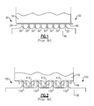
FIG. 1 illustrates a prior art labyrinth seal utilizing a straight through leakage path.
FIG. 2 illustrates a prior art labyrinth seal utilizing a staggered leakage path.
FIG. 3 illustrates a vapor cycle compressor utilizing an improved staggered seal assembly.
FIG. 4 illustrates the hybrid staggered seal assembly of the vapor cycle compressor of FIG. 3 in greater detail.
FIG. 5 illustrates a cut view of a cylindrical seal for use with the seal assembly of FIG. 4.
FIG. 6 illustrates a 3 dimensional view of the cylindrical seal of FIG. 5.
DETAILED DESCRIPTION OF THE PREFERRED EMBODIMENT
FIGS. 1 and 2 illustrate prior art labyrinth seals. FIG. 1 illustrates a labyrinth seal which has a static element 10 separating a high pressure region 20 from a low pressure region 22. The static element radially surrounds a rotating element 30. The rotating element 30 has a set of fins 32. The fins 32 are adjacent to an edge 24 of the static element 10. The gap between the fins 32 and the static element 10 is a leakage flow path 40, which allows a portion of the fluid in the high pressure region to leak into the low pressure region 22. The fins 32 and the leakage flow path 40 of FIG. 1 are enlarged for illustration purposes.
As an alternate to the straight through seal illustrated in FIG. 1, some prior art systems use a staggered seal assembly such as the one illustrated in FIG. 2. The staggered seal assembly has a static element 110 with fins 112 protruding radially inward toward a rotating element 130. The rotating element 130 also has fins 132, which extend radially outward toward the static element 110. The static element fins 112 and the rotor fins 132 are arranged in an alternating pattern with a gap between them to create a complex leakage flow path 140. The complex leakage flow path 140 results in a slower leakage from a high pressure zone 120 to a low pressure zone 122 than exists in the straight through leakage path of FIG. 1. As in FIG. 1, the fins 112, 132 and the leakage flow path are enlarged for illustrative purposes.
FIG. 3 illustrates a schematic vapor cycle compressor 198 which utilizes an improved staggered seal assembly 200. The seal assembly 200 has a static element 210 which creates the seal, and limits airflow from a high pressure side 202 of the seal to a low pressure side 204 of the seal. The static element 210 is ring shaped and surrounds the shaft 212. The static element 210 is held in place by contact with a thrust plate 230. An impeller 240 is connected to the shaft 212 and rotates along with the shaft 212. The impeller 240 also provides a staggered component 340 (pictured in FIG. 4), which aids in the formation of the seal. The seal assembly 200 has a leakage path which allows a portion of the fluid in the high pressure side 202 to travel through a gap between the static element 210 and the rotor 212 to the low pressure side 204.
As can be appreciated from FIGS. 3 and 4, the seal assembly 200 can be assembled by sliding the static element 210 up the shaft 212 until the static element 210 is in place. The thrust plate 230 then contacts the static element 210 and secures the static element 210, preventing the static element 210 from moving. The impeller 240 is then installed contacting the shaft 212 with a staggered element 340 (pictured in FIG. 4) adjacent to the static element 210 to further stagger the leakage flow path. This installation technique allows the static element 210 to be constructed out of a single piece, thereby reducing the component costs and construction time of the seal assembly 200 relative to prior art staggered seal designs. Additionally the use of a single piece for the static element 210 allows the static element 210 to be replaceable after the static element 210 is worn out, thereby allowing the seal assembly 200 to have a greater lifespan.
The static element 210 and the shaft 212 separate the high pressure side 202 from the low pressure side 204 through the use of several fins 310, 320, 330, 340. The shaft 212 has a first shaft fin 310 and a set of second shaft fins 320. The first shaft fin 310 extends farther away from the shaft 212 and into a notch 350 of the static element 210. The set of second shaft fins 320 extend away from the shaft 212 toward the static element 210 along a center portion 352 of the static element 310. The static element 210 has a static fin 330, which extends radially inward from the static element 210 toward the shaft 212. Adjacent to the static fin 330 is a staggered element fin 340. The staggered element fin 340 extends radially outward from the shaft 212 into a second notch 354 of the static element 210, and is connected to the impeller 240. In alternate applications the staggered element fin 340 could be attached to any component, which is adjacent to the high pressure side 202 of the static element 210, and which rotates along with the shaft 212.
The static element 210 is radially thinner in the notches 350, 354 than in the center portion 352. This allows the fins 310, 320, 330, 340 to create a staggered leakage flow path (illustrated in FIG. 5) while simultaneously allowing for easier manufacturing and construction of the seal assembly 200 than the prior art staggered seal assemblies. The first notch 350 and the second notch 354 further allow the first sized rotor fin 310 (in the case of the first notch 350) and the staggered component fin 340 (in the case of the second notch 354) to freely rotate without intersecting the static element 210. While the illustration of FIG. 4 shows a cut-out sectional view of the static element 210, an actual staggered seal assembly 200 will have the static element 210 radially surrounding the rotor in a uniform shape such that the cross-sectional view would be the same, regardless of where the cross-section was taken (see FIG. 6).
FIG. 5 illustrates an enlarged view of a portion of the seal assembly 200, which illustrates the leakage flow path 400 using a series of arrows. The leakage flow path 400 is forced in a staggered path around the fins 310, 320, 330, 340 as it progresses from the high pressure side 202 to the low pressure side 204 of the static element 210. This configuration achieves the benefits of the prior art staggered seal assembly (illustrated in FIG. 2) by forcing the leakage fluid through a winding path, while at the same time maintaining the ease of construction found in the prior art strait through seal assembly (illustrated in FIG. 1).
FIG. 6 illustrates a three dimensional view of the static element 210. The static element 210 has a through hole 602 which, when the static element 210 is installed, fits the shaft 212 with a gap between the static element fin 330 and the shaft 212. A first end 606 of the static element 210 has the first notch 350 and a third notch 604. A second end 608 of the static element 210 has the second notch 354 and a fourth notch 610. The third notch 604 and the fourth notch 610 allow another static component of the seal assembly 200 (pictured in FIG. 3) to grip the static element 210 and hold the static element 210 in a stationary position while the shaft 212 rotates within the through hole 602. The static element fin 330 extends from the border between the second notch 354 and the central portion 352 of the static element 210. The first notch 350 and the second notch 354 allow the first rotor fin 310 (pictured in FIG. 4) and the staggered element fin 340 (pictured in FIG. 4) to rotate freely without intersecting the static element 210.
Although an embodiment of this invention has been disclosed, a worker of ordinary skill in this art would recognize that certain modifications would come within the scope of this invention. For that reason, the following claims should be studied to determine the true scope and content of this invention.