US8074514B1 - Liquid level sensor with conductive torsion springs - Google Patents
Liquid level sensor with conductive torsion springs Download PDFInfo
- Publication number
- US8074514B1 US8074514B1 US12/471,385 US47138509A US8074514B1 US 8074514 B1 US8074514 B1 US 8074514B1 US 47138509 A US47138509 A US 47138509A US 8074514 B1 US8074514 B1 US 8074514B1
- Authority
- US
- United States
- Prior art keywords
- torsion springs
- sealed
- probes
- shafts
- electrically conductive
- Prior art date
- Legal status (The legal status is an assumption and is not a legal conclusion. Google has not performed a legal analysis and makes no representation as to the accuracy of the status listed.)
- Expired - Fee Related, expires
Links
Images


Classifications
-
- G—PHYSICS
- G01—MEASURING; TESTING
- G01F—MEASURING VOLUME, VOLUME FLOW, MASS FLOW OR LIQUID LEVEL; METERING BY VOLUME
- G01F23/00—Indicating or measuring liquid level or level of fluent solid material, e.g. indicating in terms of volume or indicating by means of an alarm
- G01F23/22—Indicating or measuring liquid level or level of fluent solid material, e.g. indicating in terms of volume or indicating by means of an alarm by measuring physical variables, other than linear dimensions, pressure or weight, dependent on the level to be measured, e.g. by difference of heat transfer of steam or water
- G01F23/24—Indicating or measuring liquid level or level of fluent solid material, e.g. indicating in terms of volume or indicating by means of an alarm by measuring physical variables, other than linear dimensions, pressure or weight, dependent on the level to be measured, e.g. by difference of heat transfer of steam or water by measuring variations of resistance of resistors due to contact with conductor fluid
- G01F23/241—Indicating or measuring liquid level or level of fluent solid material, e.g. indicating in terms of volume or indicating by means of an alarm by measuring physical variables, other than linear dimensions, pressure or weight, dependent on the level to be measured, e.g. by difference of heat transfer of steam or water by measuring variations of resistance of resistors due to contact with conductor fluid for discrete levels
- G01F23/242—Mounting arrangements for electrodes
Definitions
- This invention relates to sensing the liquid level in a container as used in a beverage brewing device or hot water container in an aircraft.
- probes mounted with springs are used. This provides an electrode without gaps to become contaminated. These probes are always oriented downward into the server. When the server is put into the coffee maker the probes are pushed out of the way by the server and then flex back into position inside the server. The probes are attached to the springs with the axis of the probes aligned with the axis of the spring coils causing the springs to flex perpendicular to the axis of the spring.
- torsion springs attached to sealed shafts rotate the probe to a downward position.
- the level sensor probes pivot about a sealed shaft when a server or other container pushes on the end of the probes.
- the torsion springs attached to the sealed shaft allow the shaft to rotate the probes to an upward position.
- the torsion springs are not overstressed, do not bend and therefore do not sever and detach.
- the torsion springs are electrically conductive, as are the shafts and probes.
- the connection between the shafts and torsion springs is a solid conductive connection.
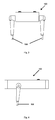
- FIG. 1 shows an exploded view of the assembly
- FIG. 2 shows an isometric view of the assembly
- FIG. 3 shows a front view of the assembly
- FIG. 4 shows a side view of the assembly
- FIG. 5 shows a top view of the assembly with the cover removed
- the present invention provides for an apparatus with a reliable sensor probe assembly to detect the surface of a liquid in a container with an upper opening, such as a server for a beverage maker or a hot water container in an aircraft.
- the sensor probe assembly 100 comprises a housing 150 , has two electrically conductive probes 106 connected via sealed rotation joints 160 with electrically conductive sealed shafts 108 .
- Housing 150 has a cover 170 and a sealed cavity 158 containing two torsion springs 110 .
- Torsion springs 110 are held in place inside sealed cavity 158 by spring channels 162 .
- One end of torsion springs 110 are fixed by screw 174 and connected electrically to sensor probe wires 118 as shown in FIG. 5 .
- the other end of sensor probe wires 118 are secured with screws 176 to cover 170 .
- Sealed shafts 108 are inserted through holes 164 in the sealed cavity 158 and secured with retainers 178 in such manner as to retain the sealed shafts 108 and allow the sealed shafts 108 to rotate in the sealed rotation joints 160 .
- Seals 172 are shown in FIG. 1 .
- the ends of sealed shafts 108 inserted into sealed cavity 158 are connected to the ends of torsion springs 110 that are not fixed.
- the connections between torsion springs 110 and sealed shafts 108 are electrically conductive. There is electrical continuity from probes 106 to sealed shafts 108 to torsion springs 110 to sensor probe wires 118 with all connections being solid, that is without any electrical slip joints or rotating electrical contact joints which could become contaminated and build up electrical resistance.
- a container is placed in a coffee maker or hot water system pushing probes 106 out of the way. This causes the probes 106 to rotate about sealed shafts 108 to an upward position. Sealed shafts 108 are connected to torsion springs 110 . The rotation of sealed shafts 108 cause torsion springs 110 to be put into torsion. Once probes 106 pass the edge of the container, torsion springs 110 cause probes 106 to rotate back to the downward position inside the container.
- the liquid makes contact with probes 106 completing an electric circuit through an electronic controller via the conductive sealed shafts 108 , torsion springs 110 and sensor probe wires 118 signaling the controller to close a solenoid valve that is filling the container.
Abstract
An assembly with liquid level sensor probes which rotate down into a container by means of torsion springs, thereby eliminating failure to the springs due to bending. The torsion springs also act as conductors in an electric circuit without any electrical slip joints or rotating electrical contact joints which can become contaminated or oxidized and thereby interrupt electric continuity of the circuit.
Description
Not Applicable
Not Applicable
Not Applicable
1. Field of Invention
This invention relates to sensing the liquid level in a container as used in a beverage brewing device or hot water container in an aircraft.
2. Prior Art
Coffee makers on aircraft are used many times per month and therefore must be very reliable. The current art, U.S. Pat. No. 4,949,627, uses “swingably” mounted electrodes to detect when the coffee maker server is full and to therefore stop filling the server. These electrodes are conductive metal segments linked together by conductive pins, bolts, and nuts. The problem with this design is the fact that over time coffee residue and oxidation builds up between the links and between the pins and links. This residue and oxidation reduces the electrical conductivity of the electrode linkage, and thus renders the electrode sensor inoperable and causing the server to overflow.
One conventional technique for solving the problem of residue interrupting electrical conductivity in electrodes is to use a probe without links. Instead of “swingably” mounted electrodes, probes mounted with springs are used. This provides an electrode without gaps to become contaminated. These probes are always oriented downward into the server. When the server is put into the coffee maker the probes are pushed out of the way by the server and then flex back into position inside the server. The probes are attached to the springs with the axis of the probes aligned with the axis of the spring coils causing the springs to flex perpendicular to the axis of the spring.
Repeated bending and overstressing of the springs causes failure of the springs and the probes to sever and detach. The current art, U.S. Pat. No. 7,017,408, attempted to eliminate the mechanical failures associated with spring mounted probes by replacing conductive probes with infrared light emitting diodes (IRED) to detect the liquid level in the server. The IRED concept has problems with the lenses becoming dirty from steam and coffee residue which cause the IRED concept to not detect the liquid surface and therefore overfilling occurs. The IRED also has difficulty detecting the liquid surface when the surface is rippled due to aircraft vibration. The IRED concept also has errors detecting the maximum allowed surface level when the aircraft is not in level flight since the liquid surface is not horizontal. Problems also occur with the IRED concept in detecting the liquid surface due to the density of steam. All of these problems cause the IRED concept to overflow the server.
In accordance with one embodiment, torsion springs attached to sealed shafts rotate the probe to a downward position. The level sensor probes pivot about a sealed shaft when a server or other container pushes on the end of the probes. The torsion springs attached to the sealed shaft allow the shaft to rotate the probes to an upward position. The torsion springs are not overstressed, do not bend and therefore do not sever and detach. The torsion springs are electrically conductive, as are the shafts and probes. The connection between the shafts and torsion springs is a solid conductive connection.
- 100 sensor probe assembly
- 106 probes
- 108 sealed shaft
- 110 torsion spring
- 118 sensor probe wire
- 150 housing
- 158 sealed cavity
- 160 sealed rotation joint
- 162 spring channel
- 164 holes in sealed cavity
- 170 cover
- 172 seal
- 174 screw
- 176 screw
- 178 retainer
The present invention provides for an apparatus with a reliable sensor probe assembly to detect the surface of a liquid in a container with an upper opening, such as a server for a beverage maker or a hot water container in an aircraft.
One embodiment of a reliable sensor probe assembly is illustrated in FIGS. 1-5 . The sensor probe assembly 100 comprises a housing 150, has two electrically conductive probes 106 connected via sealed rotation joints 160 with electrically conductive sealed shafts 108. Housing 150 has a cover 170 and a sealed cavity 158 containing two torsion springs 110. Torsion springs 110 are held in place inside sealed cavity 158 by spring channels 162. One end of torsion springs 110 are fixed by screw 174 and connected electrically to sensor probe wires 118 as shown in FIG. 5 . The other end of sensor probe wires 118 are secured with screws 176 to cover 170. Sealed shafts 108 are inserted through holes 164 in the sealed cavity 158 and secured with retainers 178 in such manner as to retain the sealed shafts 108 and allow the sealed shafts 108 to rotate in the sealed rotation joints 160. Seals 172 are shown in FIG. 1 . The ends of sealed shafts 108 inserted into sealed cavity 158 are connected to the ends of torsion springs 110 that are not fixed. The connections between torsion springs 110 and sealed shafts 108 are electrically conductive. There is electrical continuity from probes 106 to sealed shafts 108 to torsion springs 110 to sensor probe wires 118 with all connections being solid, that is without any electrical slip joints or rotating electrical contact joints which could become contaminated and build up electrical resistance.
Operation
A container is placed in a coffee maker or hot water system pushing probes 106 out of the way. This causes the probes 106 to rotate about sealed shafts 108 to an upward position. Sealed shafts 108 are connected to torsion springs 110. The rotation of sealed shafts 108 cause torsion springs 110 to be put into torsion. Once probes 106 pass the edge of the container, torsion springs 110 cause probes 106 to rotate back to the downward position inside the container. When the container is filled with liquid to a predetermined level, the liquid makes contact with probes 106 completing an electric circuit through an electronic controller via the conductive sealed shafts 108, torsion springs 110 and sensor probe wires 118 signaling the controller to close a solenoid valve that is filling the container.
Advantages
From the description above, a number of advantages of some embodiments of my sensor probe assembly become evident:
(a) Reliability of a beverage brewing device or hot water container will be increased due to the use of torsion springs that are not forced to bend, thereby eliminating failure due to overstressing of the springs.
(b) Eliminating the IRED level sensors which are prone to error detecting the fluid level surface.
(c) Eliminating overflow due to metal linkage type probes becoming contaminated or oxidized and losing electrical continuity between links.
(d) Eliminating the need for rotating electrical contact joints which can lose electrical continuity.
(e) Eliminating the need for brushes or fingers to make electrical contact which can become deformed or contaminated, thereby losing electrical continuity.
The reader will see that, according to one embodiment of the present invention, I have provided a sensor probe assembly that improves the reliability of a beverage brewing device or hot water container. This reliability improvement is due to the probes being connected to torsion springs that are not forced to bend, thereby eliminating failure due to overstressing the springs. Reliability is also improved by not having to rely on IRED sensors that are prone to error in detecting a liquid surface. While the above description contains many specificities, these should not be construed as limitations on the scope of any embodiment, but as exemplifications of the presently preferred embodiments thereof. Many other variations are possible within the teachings of the various embodiments. Thus the scope of the invention should be determined by the appended claims and their legal equivalents, and not by the examples given.
Claims (2)
1. An apparatus for detecting the liquid level in a container having an upper opening, that apparatus comprising:
(a) a housing,
(b) a plurality of electrically conductive probes, each said probe being attached to said housing by electrically conductive sealed shafts and sealed rotation joints, and
(c) a plurality of electrically conductive torsion springs contained in a sealed cavity with one end of said torsion springs being attached to said housing and the other end of said torsion springs being attached to said sealed shafts,
whereby said torsion springs cause said probes to rotate about said sealed shafts to a downward position.
2. An apparatus for detecting the liquid level in a container having an upper opening, that apparatus comprising:
(a) a housing,
(b) a plurality of electrically conductive probes, each said probe being attached to said housing by electrically conductive sealed shafts and sealed rotation joints,
(c) a plurality of electrically conductive torsion springs contained in a sealed cavity with one end of said torsion springs being attached to said housing and the other end of said torsion springs being attached to said sealed shafts, and
(d) a plurality of sensor probe wires connected to said torsion springs whereby there is electrical continuity from said probes to said sealed shafts to said torsion springs and to said sensor probe wires.
Priority Applications (1)
| Application Number | Priority Date | Filing Date | Title |
|---|---|---|---|
| US12/471,385 US8074514B1 (en) | 2009-05-24 | 2009-05-24 | Liquid level sensor with conductive torsion springs |
Applications Claiming Priority (1)
| Application Number | Priority Date | Filing Date | Title |
|---|---|---|---|
| US12/471,385 US8074514B1 (en) | 2009-05-24 | 2009-05-24 | Liquid level sensor with conductive torsion springs |
Publications (1)
| Publication Number | Publication Date |
|---|---|
| US8074514B1 true US8074514B1 (en) | 2011-12-13 |
Family
ID=45092559
Family Applications (1)
| Application Number | Title | Priority Date | Filing Date |
|---|---|---|---|
| US12/471,385 Expired - Fee Related US8074514B1 (en) | 2009-05-24 | 2009-05-24 | Liquid level sensor with conductive torsion springs |
Country Status (1)
| Country | Link |
|---|---|
| US (1) | US8074514B1 (en) |
Cited By (1)
| Publication number | Priority date | Publication date | Assignee | Title |
|---|---|---|---|---|
| US20120197113A1 (en) * | 2011-01-31 | 2012-08-02 | Sunnybrook Health Sciences Centre | Ultasonic probe with ultrasonic transducers addressable on common electrical channel |
Citations (8)
| Publication number | Priority date | Publication date | Assignee | Title |
|---|---|---|---|---|
| US4949627A (en) | 1989-03-09 | 1990-08-21 | Nordskog Robert A | Coffee maker for use in aircraft |
| US6047630A (en) | 1998-02-16 | 2000-04-11 | Be Aerospace, Inc. | Beverage brewing device having an integral beverage server locking apparatus |
| US6227101B1 (en) | 1999-12-10 | 2001-05-08 | Masoud Rabadi | Coffeemaker with automated interlocks |
| US6779435B1 (en) | 1999-02-01 | 2004-08-24 | Iacobucci S.P.A. | Machine for American style coffee for use on aircraft |
| US7017408B2 (en) | 2004-02-13 | 2006-03-28 | Be Intellectual Property, Inc. | Electro-optic liquid level sensing system for aircraft beverage brewing |
| US7210400B2 (en) | 2004-02-20 | 2007-05-01 | Jamco Corporation | Folding coffee maker |
| WO2008154698A1 (en) * | 2007-06-21 | 2008-12-24 | Breville Pty Limited | Reservoir level sensing |
| US20110011177A1 (en) * | 2007-10-24 | 2011-01-20 | B/E Intellectual Property, Inc. | Liquid level sensor for galley inserts |
-
2009
- 2009-05-24 US US12/471,385 patent/US8074514B1/en not_active Expired - Fee Related
Patent Citations (9)
| Publication number | Priority date | Publication date | Assignee | Title |
|---|---|---|---|---|
| US4949627A (en) | 1989-03-09 | 1990-08-21 | Nordskog Robert A | Coffee maker for use in aircraft |
| US6047630A (en) | 1998-02-16 | 2000-04-11 | Be Aerospace, Inc. | Beverage brewing device having an integral beverage server locking apparatus |
| US6050175A (en) | 1998-02-16 | 2000-04-18 | Be Aerospace, Inc. | Beverage brewing device having an integral beverage server locking apparatus |
| US6779435B1 (en) | 1999-02-01 | 2004-08-24 | Iacobucci S.P.A. | Machine for American style coffee for use on aircraft |
| US6227101B1 (en) | 1999-12-10 | 2001-05-08 | Masoud Rabadi | Coffeemaker with automated interlocks |
| US7017408B2 (en) | 2004-02-13 | 2006-03-28 | Be Intellectual Property, Inc. | Electro-optic liquid level sensing system for aircraft beverage brewing |
| US7210400B2 (en) | 2004-02-20 | 2007-05-01 | Jamco Corporation | Folding coffee maker |
| WO2008154698A1 (en) * | 2007-06-21 | 2008-12-24 | Breville Pty Limited | Reservoir level sensing |
| US20110011177A1 (en) * | 2007-10-24 | 2011-01-20 | B/E Intellectual Property, Inc. | Liquid level sensor for galley inserts |
Cited By (2)
| Publication number | Priority date | Publication date | Assignee | Title |
|---|---|---|---|---|
| US20120197113A1 (en) * | 2011-01-31 | 2012-08-02 | Sunnybrook Health Sciences Centre | Ultasonic probe with ultrasonic transducers addressable on common electrical channel |
| US9700280B2 (en) * | 2011-01-31 | 2017-07-11 | Sunnybrook Health Sciences Centre | Ultrasonic probe with ultrasonic transducers addressable on common electrical channel |
Similar Documents
| Publication | Publication Date | Title |
|---|---|---|
| US8061263B1 (en) | Sensor head and brew cup for a beverage brewing device | |
| CN107874612B (en) | Cooking utensil | |
| KR100854267B1 (en) | Fabrication method of pogo pin and test socket using the same | |
| CN102483435A (en) | Electrically conductive kelvin contacts for microcircuit tester | |
| EP1889331A2 (en) | Electrical connector with embedded canted coil spring | |
| US8074514B1 (en) | Liquid level sensor with conductive torsion springs | |
| CN102448354B (en) | Electric domestic appliance for food preparation, comprising a base for receiving a working vessel including a heating plate | |
| TW201423108A (en) | Connection terminal and conductivity inspecting equipment using same | |
| JP2014081375A (en) | Ground contact point of integrated circuit inspection device | |
| US20180301840A1 (en) | Reversible connector interface | |
| CN110391568A (en) | High circuit count electric connector | |
| TWI604487B (en) | Electronic device and pressure sensor thereof | |
| CN204931247U (en) | A kind of anti-overflow Normal juice machine | |
| CN203405265U (en) | Water temperature and water level detector of solar water heater | |
| CN102869302B (en) | Pressure transducer for medical use and contact holder | |
| EP2208030B1 (en) | Liquid level sensor for galley inserts | |
| US6943661B2 (en) | Quick-connect positive temperature coefficient of resistance resistor/overload assembly and method | |
| JP5113139B2 (en) | Electric water heater | |
| US10883869B2 (en) | Retainer for a moveable arm of a fluid level sensor | |
| SE442252B (en) | ELECTRICAL SWITCH | |
| CN207074221U (en) | Test conductor | |
| EP1087685A1 (en) | Electrical cooking appliance with removable bowl | |
| JP4992689B2 (en) | Magnetic position detector | |
| JP5248356B2 (en) | Temperature detector structure | |
| CN101846539A (en) | Dual-purpose sensor and electric heating kettle with the same |
Legal Events
| Date | Code | Title | Description |
|---|---|---|---|
| REMI | Maintenance fee reminder mailed | ||
| LAPS | Lapse for failure to pay maintenance fees | ||
| STCH | Information on status: patent discontinuation |
Free format text: PATENT EXPIRED DUE TO NONPAYMENT OF MAINTENANCE FEES UNDER 37 CFR 1.362 |
|
| FP | Lapsed due to failure to pay maintenance fee |
Effective date: 20151213 |