US8073049B2 - Method of coding a video signal - Google Patents
Method of coding a video signal Download PDFInfo
- Publication number
- US8073049B2 US8073049B2 US12/068,025 US6802508A US8073049B2 US 8073049 B2 US8073049 B2 US 8073049B2 US 6802508 A US6802508 A US 6802508A US 8073049 B2 US8073049 B2 US 8073049B2
- Authority
- US
- United States
- Prior art keywords
- frames
- decoder
- description
- video
- decoding
- Prior art date
- Legal status (The legal status is an assumption and is not a legal conclusion. Google has not performed a legal analysis and makes no representation as to the accuracy of the status listed.)
- Expired - Fee Related, expires
Links
Images


Classifications
-
- H—ELECTRICITY
- H04—ELECTRIC COMMUNICATION TECHNIQUE
- H04N—PICTORIAL COMMUNICATION, e.g. TELEVISION
- H04N19/00—Methods or arrangements for coding, decoding, compressing or decompressing digital video signals
- H04N19/10—Methods or arrangements for coding, decoding, compressing or decompressing digital video signals using adaptive coding
- H04N19/134—Methods or arrangements for coding, decoding, compressing or decompressing digital video signals using adaptive coding characterised by the element, parameter or criterion affecting or controlling the adaptive coding
- H04N19/136—Incoming video signal characteristics or properties
-
- H—ELECTRICITY
- H04—ELECTRIC COMMUNICATION TECHNIQUE
- H04N—PICTORIAL COMMUNICATION, e.g. TELEVISION
- H04N19/00—Methods or arrangements for coding, decoding, compressing or decompressing digital video signals
- H04N19/10—Methods or arrangements for coding, decoding, compressing or decompressing digital video signals using adaptive coding
- H04N19/102—Methods or arrangements for coding, decoding, compressing or decompressing digital video signals using adaptive coding characterised by the element, parameter or selection affected or controlled by the adaptive coding
- H04N19/12—Selection from among a plurality of transforms or standards, e.g. selection between discrete cosine transform [DCT] and sub-band transform or selection between H.263 and H.264
-
- H—ELECTRICITY
- H04—ELECTRIC COMMUNICATION TECHNIQUE
- H04N—PICTORIAL COMMUNICATION, e.g. TELEVISION
- H04N19/00—Methods or arrangements for coding, decoding, compressing or decompressing digital video signals
- H04N19/10—Methods or arrangements for coding, decoding, compressing or decompressing digital video signals using adaptive coding
- H04N19/169—Methods or arrangements for coding, decoding, compressing or decompressing digital video signals using adaptive coding characterised by the coding unit, i.e. the structural portion or semantic portion of the video signal being the object or the subject of the adaptive coding
- H04N19/17—Methods or arrangements for coding, decoding, compressing or decompressing digital video signals using adaptive coding characterised by the coding unit, i.e. the structural portion or semantic portion of the video signal being the object or the subject of the adaptive coding the unit being an image region, e.g. an object
- H04N19/172—Methods or arrangements for coding, decoding, compressing or decompressing digital video signals using adaptive coding characterised by the coding unit, i.e. the structural portion or semantic portion of the video signal being the object or the subject of the adaptive coding the unit being an image region, e.g. an object the region being a picture, frame or field
-
- H—ELECTRICITY
- H04—ELECTRIC COMMUNICATION TECHNIQUE
- H04N—PICTORIAL COMMUNICATION, e.g. TELEVISION
- H04N19/00—Methods or arrangements for coding, decoding, compressing or decompressing digital video signals
- H04N19/44—Decoders specially adapted therefor, e.g. video decoders which are asymmetric with respect to the encoder
-
- H—ELECTRICITY
- H04—ELECTRIC COMMUNICATION TECHNIQUE
- H04N—PICTORIAL COMMUNICATION, e.g. TELEVISION
- H04N19/00—Methods or arrangements for coding, decoding, compressing or decompressing digital video signals
- H04N19/46—Embedding additional information in the video signal during the compression process
-
- H—ELECTRICITY
- H04—ELECTRIC COMMUNICATION TECHNIQUE
- H04N—PICTORIAL COMMUNICATION, e.g. TELEVISION
- H04N19/00—Methods or arrangements for coding, decoding, compressing or decompressing digital video signals
- H04N19/60—Methods or arrangements for coding, decoding, compressing or decompressing digital video signals using transform coding
- H04N19/61—Methods or arrangements for coding, decoding, compressing or decompressing digital video signals using transform coding in combination with predictive coding
-
- H—ELECTRICITY
- H04—ELECTRIC COMMUNICATION TECHNIQUE
- H04N—PICTORIAL COMMUNICATION, e.g. TELEVISION
- H04N21/00—Selective content distribution, e.g. interactive television or video on demand [VOD]
- H04N21/20—Servers specifically adapted for the distribution of content, e.g. VOD servers; Operations thereof
- H04N21/23—Processing of content or additional data; Elementary server operations; Server middleware
- H04N21/234—Processing of video elementary streams, e.g. splicing of video streams, manipulating MPEG-4 scene graphs
- H04N21/2343—Processing of video elementary streams, e.g. splicing of video streams, manipulating MPEG-4 scene graphs involving reformatting operations of video signals for distribution or compliance with end-user requests or end-user device requirements
- H04N21/23439—Processing of video elementary streams, e.g. splicing of video streams, manipulating MPEG-4 scene graphs involving reformatting operations of video signals for distribution or compliance with end-user requests or end-user device requirements for generating different versions
-
- H—ELECTRICITY
- H04—ELECTRIC COMMUNICATION TECHNIQUE
- H04N—PICTORIAL COMMUNICATION, e.g. TELEVISION
- H04N21/00—Selective content distribution, e.g. interactive television or video on demand [VOD]
- H04N21/20—Servers specifically adapted for the distribution of content, e.g. VOD servers; Operations thereof
- H04N21/25—Management operations performed by the server for facilitating the content distribution or administrating data related to end-users or client devices, e.g. end-user or client device authentication, learning user preferences for recommending movies
- H04N21/262—Content or additional data distribution scheduling, e.g. sending additional data at off-peak times, updating software modules, calculating the carousel transmission frequency, delaying a video stream transmission, generating play-lists
- H04N21/26275—Content or additional data distribution scheduling, e.g. sending additional data at off-peak times, updating software modules, calculating the carousel transmission frequency, delaying a video stream transmission, generating play-lists for distributing content or additional data in a staggered manner, e.g. repeating movies on different channels in a time-staggered manner in a near video on demand system
-
- H—ELECTRICITY
- H04—ELECTRIC COMMUNICATION TECHNIQUE
- H04N—PICTORIAL COMMUNICATION, e.g. TELEVISION
- H04N21/00—Selective content distribution, e.g. interactive television or video on demand [VOD]
- H04N21/40—Client devices specifically adapted for the reception of or interaction with content, e.g. set-top-box [STB]; Operations thereof
- H04N21/43—Processing of content or additional data, e.g. demultiplexing additional data from a digital video stream; Elementary client operations, e.g. monitoring of home network or synchronising decoder's clock; Client middleware
- H04N21/4302—Content synchronisation processes, e.g. decoder synchronisation
- H04N21/4305—Synchronising client clock from received content stream, e.g. locking decoder clock with encoder clock, extraction of the PCR packets
Definitions
- the present invention relates to a method and apparatus for encoding of a video sequence.
- a video sequence consists of a number of still images called frames. Coding of a video sequence, video coding, is done by describing the frames as bit-efficiently as possible. To do this, redundancy in the video sequence is exploited. There are three types of redundancies that can be exploited, temporal redundancy, spatial redundancy and spectral redundancy. Temporal redundancy is the redundancy between two frames, while spatial redundancy is the redundancy within a frame. Spectral redundancy is the redundancy between different colour components in the video. In the following we will not consider the spectral redundancy.
- Video coding standards define a number of frame types, out of which the I-frame and the P-frame are common to most standards.
- the I-frame is coded by exploiting spatial redundancy solely, resulting in a representation that is independent of all other frames.
- P-frames are coded by exploiting both temporal and spatial redundancies. This leads to a more compact representation of the frame, while at the same time making this representation dependent of an other frame (in most cases the previous one).
- the applications have mainly included videoconferencing and videotelephony over circuit-switched networks, but also storing video material for later retrieval, e.g., the DVD.
- Newer standards e.g., MPEG-4 and H.264, have a performance that is significantly improved over their predecessors and achieve low bit-rates for given video quality.
- the main ideas of using different frame types have been preserved and the performance improvement is a result of refinement of the methods used in older standards.
- One such refinement is that a frame can be segmented into smaller regions called slices, and the method of using I frames and P frames can be applied on individual slices.
- An object of the present invention is to provide encoding and decoding of a video sequence which improves the perceptual video quality with only a moderate increase of the bit-rate for transferring the encoded video sequence.
- a method and an apparatus for encoding a video sequence, and a method and an apparatus for decoding a video sequence, in accordance with the present invention are defined in the appended independent claims.
- the invention is based on the idea of using two or more coding units for encoding two or more descriptions of the same video sequence, wherein the encoding units perform their encoding operations displaced in time in relation to each other.
- the invention also includes the use of two or more decoding units for decoding two or more descriptions of the same video sequence, wherein the decoding units perform their decoding operations displaced in time in relation to each other.
- the use of more than one encoder for encoding the same video sequence has the advantage of increasing the possibility that one or more encoded descriptions of a video sequence frame are received without error, even though one or more encoded descriptions of the same frame are non-existent due to an error or delay when transferring the encoded video sequence over a network from a transmitting end to a receiving end.
- By displacing the encoding operations of the encoders in time the probability that the received encoded sequences include propagated errors at the same time will be reduced. This is because the different encoded sequences will have some kind of zero states occurring at different points in time. With increased time since the last zero state for an encoded sequence, the higher probability of a propagated error for that encoded sequence.
- Another advantage of displacing the encoding operations of the encoders in time is achieved in case of a disruption in the network transferring all the encoded video sequences and effecting all the sequences at the same time.
- the time until one of the video sequences includes a zero state after the disruption will in most cases be smaller, as compared to the case with no displacement of the zero state.
- the time to the next zero state for all the multiple encoded sequences will be the same as in the case when only one single encoded sequence is used for transferring the video.
- the present inventions has jitter buffer arranged at the receiving end, preferably one jitter buffer for each description received, and, thus, for each decoder.
- the decoders will be provided with data to be decoded from respective jitter buffers. According to the invention, the decoding operations of one decoder are then displaced in time with regard to decoding operations of another decoder.
- a zero state as discussed above corresponds to an intra-encoding operation, i.e. an encoding operation exploiting spatial redundancy only, and the encoding operations between two zero states of the same encoded video sequence correspond to inter-encoding operations, i.e. encoding operations exploiting temporal redundancy between successive points of time of encoding.
- the intra-encoding and inter-encoding may be used on a frame-by-frame basis of the video sequence, or on a slice-by-slice basis, wherein a slice corresponds to a segment of a frame.
- the intra-encoding and inter-encoding correspond to I type and P type encoding, respectively.
- the invention is applicable both for video coding standards in which the encoding uses I/P frames and video coding standards using I/P slices. Consequently, as the invention does not depend on whether successive full frames or successive slices of frames are encoded using the I/P concept, the following description will use the term I/P frame as general notation for both I/P frame and I/P slice. Thus, whenever I and P frames are discussed and described, the same description applies for I and P slices.
- the inter-encoded frames/slices of the present invention can be implemented with different kinds of predictive frames/slices, e.g. B type (Bi-predictive encoding), and that the reference to P type encoding merely discloses an exemplifying embodiment.
- the present invention provides video sequence encoding using two or more encoders such that shorter error propagation on an average is provided, which results in perceptually improved quality of the displayed video at a receiving end after decoding of the video sequences.
- displacing the encoding operations for different encoders in time does not increase the bit-rate for transferring the different encoded video sequences, as compared to transferring the same number of encoded video sequences without any displacement of the encoding operations.
- the present invention improves the video quality by ensuring robustness against transmission errors.
- FIG. 1 schematically shows an exemplifying overall system environment in which various embodiments of the invention may be included and arranged to operate;
- FIG. 2 schematically shows how to obtain several different descriptions of a video frame (or slice of a video frame) for encoding of each of the description by a separate encoder;
- FIG. 3 shows an embodiment of the invention where intra-encoding operations of each encoded video sequence among three encoded video sequences are displaced in relation to the intra-encoding operations of the other encoded video sequences;
- FIG. 4 shows an embodiment of the invention where intra-encoding operations of one encoded video sequence is displaced in relation to the intra-encoding operations of another encoded video sequences.
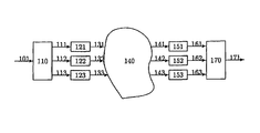
- FIG. 1 schematically shows an exemplifying overall system environment in which the different embodiments of the invention may be included and arranged to operate.
- FIG. 1 a digitized video signal 101 , divided into frames, is input, each frame representing a still image in time.
- a video signal can be divided into multiple descriptions. Each description is then encoded in a separate coding unit which is an implementation of an existing standard coder. This implies that there are I-frames and P-frames for each description. In case all descriptions are received at the receiver end, the best quality of video is obtained. In case there are errors in the transmission, affecting a number of descriptions, these descriptions are disregarded until they have been updated by an I-frame. Of course, this has the effect that the quality of the video is reduced temporarily.
- the descriptions in a multiple description video encoding setup can relate to each other in a number of ways. First of all, they can be either equivalent or non-equivalent, i.e., each description results in the same quality or a differing quality compared to another description. Whether the descriptions are equivalent or not, they can (i) be fully redundant, i.e., several descriptions are replications of one another, (ii) have zero redundancy, i.e., the descriptions have no mutual information and (iii) be redundant to some extent, i.e. there is some mutual information between the descriptions. How the descriptions relate can affect the overall performance on different networks.
- the transmitting end includes three encoders 121 , 122 and 123 .
- These three encoders are preferably standard encoders operating in accordance with the H.263, MPEG-2, H.264, or MPEG-4 video coding standards.
- the three encoders all handle their respective description in a similar manner, i.e. encode the received description using I-frames and P-frames (or when applicable, I-slices and P-slices) in accordance with the video coding standard used.
- the difference between the three encoders themselves is the time during which they perform intra-encoding operations.
- the receiving end includes three decoders 151 , 152 and 153 , also preferably being standard encoders operating in accordance with the H.263, MPEG-2, H.264, or MPEG-4 video coding standards.
- Each decoder 151 , 152 , 153 decodes a respective description 111 , 112 , 113 of the video signal.
- the three decoders all handle their respective description in a similar manner, i.e. decode the received encoded description consisting of I-frames and P-frames (or when applicable, I-slices and P-slices) in accordance with the video coding standard used.
- the difference between the three decoders themselves is the time during which they perform intra-decoding operations.
- the sequence of decoded I-frames and P-frames differ between the three encoders.
- the video signal 101 is input to a sub-sampling unit 110 .
- the sub-sampling unit sub-samples (in time or space, i.e. performs temporal or spatial sub-sampling) the input video sequence signal 101 into multiple, differing descriptions 111 , 112 and 113 of the video signal 101 .
- the receiving end includes an up-sampling unit 170 that performs the inverse procedure of the sub-sampling procedure, i.e. rearranges the decoded descriptions, decoded by decoders 151 , 152 and 153 , into one set of successive video frames.
- the descriptions 111 , 112 and 113 are identical, in which case the unit referenced as 110 is a replication unit replicating the input video signal 101 into three identical descriptions 111 , 112 and 113 . Consequently, in this alternative embodiment, the up-sampling unit 170 may simply be a unit responsible for discarding redundant decoded description (or for merging decoded descriptions if these are not fully redundant). That is, if two or more descriptions 161 , 162 , 163 are decoded by respective decoders 151 , 152 and 153 at the receiving end without errors, and if the descriptions are fully redundant, all but one of the decoded descriptions may simply be discarded by the unit 170 .
- This exemplified sub-sampling procedure assigns pixels from the input video still images to the three descriptions 111 , 112 and 113 .
- An input video image, or frame, 201 is here five pixels high and nine pixels wide.
- the pixels are assigned to descriptions column-wise: columns one, four and seven are assigned to description one, denoted 202 , columns two, five and eight are assigned to description two, denoted 203 , and columns three, six and nine are assigned to description three, denoted 204 .
- Each pixel is named in the figure and can be located in its description.
- the sub-sampling procedure of FIG. 2 is not the only one that can be used. There are other possible sub-sampling procedures, which also can be incorporated with the invention. Depending on the number of descriptions in the multiple description coding setup, so called quincunx sub-sampling, temporal sub-sampling and poly-phase sub-sampling can be used. In quincunx sub sampling, two descriptions are assigned the pixels in a checker-board fashion, the (odd-row, odd-column) pixels and the (even-row, even-column) pixels are assigned to one description, while the (odd-row, even-column) pixels and the (even-row, odd-column) pixels are assigned to the other description.
- temporal sub-sampling the number of descriptions is arbitrary. For example, assigning every third frame starting from frame one to description one, every third frame starting from frame two to description two and every third frame starting from frame three to description three, which yields three descriptions.
- Poly-phase sub-sampling is performed by sub-sampling the original frame along rows (by factor R), producing R temporary descriptions. These R temporary descriptions are then sub-sampled (by factor C), each producing C descriptions and a total of R*C descriptions.
- each description is independently encoded by its respective encoder 121 , 122 and 123 .
- each encoder encodes its input description so as to output the encoded video description as a series of I frames and P frames.
- the intra-encoding operations applied to each video sequence description among three different video sequence descriptions are displaced in relation to the intra-encoding operations applied to the other video sequence descriptions.
- the independency of the corresponding three encoding units is exploited by displacing the I frames to be interlaced in time such that the temporal distance between two (in different encoded descriptions) following I-frames is always equal.
- the group of pictures (GOP) length for each encoded description is six frames, while the distance between two I-frames is two frames.
- the first frame of each description is coded as an I-frame. This is done to get a good reference for prediction in all the encoded descriptions.
- intra-decoding operations applied to each received video sequence description among three different video sequence descriptions are displaced in relation to the intra-decoding operations applied to the other video sequence descriptions.
- the displacement of the intra-decoding operations of two decoders corresponds to the temporal distance between two I-frames of respective encoded descriptions that are to be decoded.
- each coded description 131 - 133 is sent over the network 140 .
- the network is such that some of the encoded description frames may be transferred with errors or be delayed, which in a packet switched network results in missing video data for the frames in question. This behaviour is typical of packet-switched networks.
- the encoded descriptions 141 - 143 that arrive at the receiving end are decoded in respective decoders 151 - 153 .
- the final result is obtained by up-sampling of the decoded descriptions 161 - 163 in up-sampling unit 170 .
- the up-sampling procedure is the inverse of the sub-sampling procedure, i.e. the pixels are rearranged from the three descriptions into one final frame.
- the final result 171 is a digital representation of the video that was input at the receiving end and is sent for further processing, e.g., displaying on a monitor.
- Some of the descriptions of a current frame may be lost, delayed or corrupted, resulting in a treatment as being non-existent. This will result in a propagated error in the decoded representation of the description.
- the propagated error is caused by the dependence of frames which causes all inter-coded frames following an erroneous frame to be erroneous.
- a non-existent or corrupted description is disregarded by up-sampling unit 170 and its pixels are instead estimated from the pixels of the other descriptions. This can be done in an interpolating manner, e.g., pixel b 1 in FIG. 2 is estimated as the mean of a 1 and c 1 .
- a description is disregarded as long as it is corrupt. Hence, it will be taken in use only when an I-frame of that description arrives at the receiver end. Having access to as many non-corrupt descriptions as possible results in the best quality, why one wants to maximize the number of non-corrupt descriptions at all times.
- the expected number of descriptions available at any time will be greater than if the same frame would have been encoded as an I-frame for every description. This follows from the fact that the interval between I-frames is smaller and the probability of a propagated error will at any time be different for the three different descriptions.
- the up-sampling unit 170 In order to for the up-sampling unit 170 to be able to decide how to arrange the received descriptions, i.e. the output of the decoders, into one set of successive video frames, it needs to keep track of the validity of the received descriptions. This is preferrably done by including output validity flags in the up-sampling unit, one output validity flag for each decoder connected to the up-sampling unit.
- a decoder's output validity flag indicates whether the description from that decoder is corrupted or non-corrupted, and, thus, whether that description should be used when arranging the received descriptions into one set of successive video frames.
- a decoder When a decoder determines a description to be lost, delayed or corrupted, it signals to the up-sampling unit that the corresponding output validity flag should be set to corrupted. When a decoder decodes an I frame, it signals to the up-sampling unit that the corresponding output validity flag should be set to non-corrupted. Thus, the up-sampling unit 170 will at every time instance be able keep track of the validity of each one of the descriptions received from the decoders.
- the above design of separate signalling for each decoder with regard to setting output validity as non-corrupted is due to the fact that the I frames of the different descriptions are displaced in time. In comparison, in a design in which the I frames of the different descriptions are not displaced in time, it is sufficient with a single signalling for all descriptions when the I frames are decoded.
- FIG. 4 another embodiment of the invention is described.
- the independence of the coding units is in this embodiment exploited by placing the I-frames in the multiple descriptions such that the expected distortion at the receiver end is minimized.
- the I frames of the different descriptions are placed based on calculations that utilize known transmission error probabilities, i.e. known network characteristics.
- FIG. 4 shows an example with two descriptions in which the probability of transmission error for the upper (in FIG. 4 ) description is assumed or known to be lower than the probability of transmission error for the lower (in FIG. 4 ) description. In this way the I-frames are interlaced such that the expected distortion at the receiver end is minimized.
- the sender can choose to use the information regarding different transmission error probabilities for the two transferred encoded descriptions to improve the performance, not only in comparison to placement of the I frames at the same time for both descriptions, but also in comparison to the placement of I frames described in the previous embodiment.
- the displacement of the decoding operations at the receiving end corresponds to the placement of the I-frames shown in FIG. 4 .
- the probability of error for the upper description is lower than the probability of error for the lower description, then it is advantageous to move the relative placement of the I frames of the encoded descriptions in accordance with what is shown in FIG. 4 .
- the lower description can be seen as complementary, i.e., it is used to decrease the probability of error when the upper description is no longer reliable. Since, the upper description has lower probability of error, the I frame of the lower description can be moved to the right (to occur later in time) and the upper description is trusted with a greater number of P frames before the lower description is used to decrease the overall probability of error. For example, with the time from left to right in FIG. 4 , the first P frame after the I frame of the lower description occurs at the same time as the fifth P frame of the upper description, thereby providing a decreased overall probability of error. The situation for the lower description is the opposite.
- the optimal placement of the I-frames for descriptions one and two can with given probabilities of error and expected distortion be calculated in a minimization problem.
- the expected value of the total distortion is minimized with respect to the relative placement of the I-frames.
- the expression for the expected distortion is shown to occur in periods, why it is sufficient to solve the minimization problem only for an interval between two I-frames in either description.
- the expression for the expected distortion in this interval is differentiated with respect to the length of I-frame displacement, giving an extremum. Since, the problem now lies in an interval, the minimum is found by evaluating the expected distortion at the extremum and at the boundaries of the interval. This will be described further in the following.
- ⁇ ln ⁇ ( - ⁇ / ⁇ ) ln ⁇ ( r A ) + ln ⁇ ( r B ) and is dependent only on r A and r B , i.e., the probabilities that the transmission in the channels will remain error free if the previous transmission was error free.
Abstract
Description
| Variable | Meaning | ||
| pX | Probability that channel X is in state 1 if | ||
| it previously was in state 0. | |||
| qX | Probability that channel X is in state 0 if | ||
| it previously was in state 1. | |||
| D0 | Distortion of the output video if both | ||
| descriptions are received. | |||
| DX | Distortion of the output video if only | ||
| description X is received. | |||
| DT | Distortion of the output video if no | ||
| descriptions are received. | |||
Let us define the following variables to simplify notation.
The optimization problem is to minimize the expectation of distortion D over all frames kε{−κ,κ}
for the discrete displacement variable Δε{0,K−1} where K denotes the I-frame period length.
where
denotes the modulo b division of a.
Let us approximate that the distortion summation is represented by the following integral, in which the frame number kε(−κ,κ), and the displacement variable
-
- Δε[0,K) are continuous.
where D1=D0−DA−DB+DT and D2=DB−DT.
the extremum is found in the following equation.
where γ≡rB κ−1−RrB κ+R and α≡R(1−rA κ)rB κ.
and is dependent only on rA and rB, i.e., the probabilities that the transmission in the channels will remain error free if the previous transmission was error free.
and D(Δ=K−1). The brackets └·┘ and ┌·┐ denote the floor and ceil operations, respectively.
Claims (18)
Priority Applications (4)
| Application Number | Priority Date | Filing Date | Title |
|---|---|---|---|
| US12/068,025 US8073049B2 (en) | 2007-02-01 | 2008-01-31 | Method of coding a video signal |
| US13/281,087 US8582662B2 (en) | 2007-02-01 | 2011-10-25 | Method of coding a video signal |
| US14/077,304 US9137561B2 (en) | 2007-02-01 | 2013-11-12 | Independent temporally concurrent video stream coding |
| US14/834,624 US10291917B2 (en) | 2007-02-01 | 2015-08-25 | Independent temporally concurrent Video stream coding |
Applications Claiming Priority (2)
| Application Number | Priority Date | Filing Date | Title |
|---|---|---|---|
| US89871807P | 2007-02-01 | 2007-02-01 | |
| US12/068,025 US8073049B2 (en) | 2007-02-01 | 2008-01-31 | Method of coding a video signal |
Related Child Applications (1)
| Application Number | Title | Priority Date | Filing Date |
|---|---|---|---|
| US13/281,087 Continuation US8582662B2 (en) | 2007-02-01 | 2011-10-25 | Method of coding a video signal |
Publications (2)
| Publication Number | Publication Date |
|---|---|
| US20080205520A1 US20080205520A1 (en) | 2008-08-28 |
| US8073049B2 true US8073049B2 (en) | 2011-12-06 |
Family
ID=39715875
Family Applications (4)
| Application Number | Title | Priority Date | Filing Date |
|---|---|---|---|
| US12/068,025 Expired - Fee Related US8073049B2 (en) | 2007-02-01 | 2008-01-31 | Method of coding a video signal |
| US13/281,087 Expired - Fee Related US8582662B2 (en) | 2007-02-01 | 2011-10-25 | Method of coding a video signal |
| US14/077,304 Expired - Fee Related US9137561B2 (en) | 2007-02-01 | 2013-11-12 | Independent temporally concurrent video stream coding |
| US14/834,624 Active 2030-02-26 US10291917B2 (en) | 2007-02-01 | 2015-08-25 | Independent temporally concurrent Video stream coding |
Family Applications After (3)
| Application Number | Title | Priority Date | Filing Date |
|---|---|---|---|
| US13/281,087 Expired - Fee Related US8582662B2 (en) | 2007-02-01 | 2011-10-25 | Method of coding a video signal |
| US14/077,304 Expired - Fee Related US9137561B2 (en) | 2007-02-01 | 2013-11-12 | Independent temporally concurrent video stream coding |
| US14/834,624 Active 2030-02-26 US10291917B2 (en) | 2007-02-01 | 2015-08-25 | Independent temporally concurrent Video stream coding |
Country Status (1)
| Country | Link |
|---|---|
| US (4) | US8073049B2 (en) |
Cited By (1)
| Publication number | Priority date | Publication date | Assignee | Title |
|---|---|---|---|---|
| US9191671B2 (en) | 2012-04-19 | 2015-11-17 | Vid Scale, Inc. | System and method for error-resilient video coding |
Families Citing this family (2)
| Publication number | Priority date | Publication date | Assignee | Title |
|---|---|---|---|---|
| GB2505912B (en) * | 2012-09-14 | 2015-10-07 | Canon Kk | Method and device for generating a description file, and corresponding streaming method |
| WO2019210152A1 (en) * | 2018-04-26 | 2019-10-31 | Phenix Real Time Solutions, Inc. | Adaptive bit-rate methods for live broadcasting |
Citations (15)
| Publication number | Priority date | Publication date | Assignee | Title |
|---|---|---|---|---|
| DE19531847A1 (en) | 1995-08-29 | 1997-03-06 | Sel Alcatel Ag | Device for storing video image data |
| US20030007515A1 (en) * | 2001-07-03 | 2003-01-09 | Apostolopoulos John G. | System and method for receiving mutiple description media streams in fixed and mobile streaming media systems |
| US20030039308A1 (en) * | 2001-08-15 | 2003-02-27 | General Instrument Corporation | First pass encoding of I and P-frame complexity for compressed digital video |
| US20030067938A1 (en) | 2001-10-08 | 2003-04-10 | Kurt Schmidt | Method for determining a time offset of a CDMA signal |
| US20040120358A1 (en) | 2002-12-19 | 2004-06-24 | Sony Corporation | System and method for intraframe timing in multiplexed channel |
| US20040213345A1 (en) * | 2002-09-04 | 2004-10-28 | Microsoft Corporation | Multi-resolution video coding and decoding |
| EP1578131A1 (en) | 2004-03-18 | 2005-09-21 | STMicroelectronics S.r.l. | Encoding/decoding methods and systems, computer program products therefor |
| US6965643B1 (en) * | 1998-12-18 | 2005-11-15 | Canon Kabushiki Kaisha | Image processing apparatus and method, and storage medium storing image processing program |
| EP1615441A1 (en) | 2004-07-06 | 2006-01-11 | STMicroelectronics S.r.l. | Multiple description coding combined with channel encoding |
| EP1638344A2 (en) | 2004-09-21 | 2006-03-22 | D & M Holdings, Inc. | Recorder, player |
| US20060114995A1 (en) * | 2004-12-01 | 2006-06-01 | Joshua Robey | Method and system for high speed video encoding using parallel encoders |
| US20060126733A1 (en) | 2003-01-28 | 2006-06-15 | Boyce Jill M | Robust mode staggercasting without artifacts |
| US20070047650A1 (en) * | 2005-08-29 | 2007-03-01 | Antonio Vilei | Method for encoding signals, related systems and program product therefor |
| US20070092004A1 (en) * | 2005-10-26 | 2007-04-26 | Cheng-Tsai Ho | Memory sharing in video transcoding and displaying |
| US20080267290A1 (en) * | 2004-04-08 | 2008-10-30 | Koninklijke Philips Electronics N.V. | Coding Method Applied to Multimedia Data |
Family Cites Families (9)
| Publication number | Priority date | Publication date | Assignee | Title |
|---|---|---|---|---|
| US6357045B1 (en) * | 1997-03-31 | 2002-03-12 | Matsushita Electric Industrial Co., Ltd. | Apparatus and method for generating a time-multiplexed channel surfing signal at television head-end sites |
| US20030185455A1 (en) * | 1999-02-04 | 2003-10-02 | Goertzen Kenbe D. | Digital image processor |
| US7072393B2 (en) * | 2001-06-25 | 2006-07-04 | International Business Machines Corporation | Multiple parallel encoders and statistical analysis thereof for encoding a video sequence |
| JP3866538B2 (en) * | 2001-06-29 | 2007-01-10 | 株式会社東芝 | Video coding method and apparatus |
| US9894379B2 (en) * | 2001-07-10 | 2018-02-13 | The Directv Group, Inc. | System and methodology for video compression |
| KR100973216B1 (en) * | 2002-04-23 | 2010-07-30 | 노키아 코포레이션 | Method and device for indicating quantizer parameters in a video coding system |
| US7668712B2 (en) * | 2004-03-31 | 2010-02-23 | Microsoft Corporation | Audio encoding and decoding with intra frames and adaptive forward error correction |
| JP2006311366A (en) * | 2005-04-28 | 2006-11-09 | Matsushita Electric Ind Co Ltd | Image recorder and method for driving image recorder |
| US8340183B2 (en) * | 2007-05-04 | 2012-12-25 | Qualcomm Incorporated | Digital multimedia channel switching |
-
2008
- 2008-01-31 US US12/068,025 patent/US8073049B2/en not_active Expired - Fee Related
-
2011
- 2011-10-25 US US13/281,087 patent/US8582662B2/en not_active Expired - Fee Related
-
2013
- 2013-11-12 US US14/077,304 patent/US9137561B2/en not_active Expired - Fee Related
-
2015
- 2015-08-25 US US14/834,624 patent/US10291917B2/en active Active
Patent Citations (15)
| Publication number | Priority date | Publication date | Assignee | Title |
|---|---|---|---|---|
| DE19531847A1 (en) | 1995-08-29 | 1997-03-06 | Sel Alcatel Ag | Device for storing video image data |
| US6965643B1 (en) * | 1998-12-18 | 2005-11-15 | Canon Kabushiki Kaisha | Image processing apparatus and method, and storage medium storing image processing program |
| US20030007515A1 (en) * | 2001-07-03 | 2003-01-09 | Apostolopoulos John G. | System and method for receiving mutiple description media streams in fixed and mobile streaming media systems |
| US20030039308A1 (en) * | 2001-08-15 | 2003-02-27 | General Instrument Corporation | First pass encoding of I and P-frame complexity for compressed digital video |
| US20030067938A1 (en) | 2001-10-08 | 2003-04-10 | Kurt Schmidt | Method for determining a time offset of a CDMA signal |
| US20040213345A1 (en) * | 2002-09-04 | 2004-10-28 | Microsoft Corporation | Multi-resolution video coding and decoding |
| US20040120358A1 (en) | 2002-12-19 | 2004-06-24 | Sony Corporation | System and method for intraframe timing in multiplexed channel |
| US20060126733A1 (en) | 2003-01-28 | 2006-06-15 | Boyce Jill M | Robust mode staggercasting without artifacts |
| EP1578131A1 (en) | 2004-03-18 | 2005-09-21 | STMicroelectronics S.r.l. | Encoding/decoding methods and systems, computer program products therefor |
| US20080267290A1 (en) * | 2004-04-08 | 2008-10-30 | Koninklijke Philips Electronics N.V. | Coding Method Applied to Multimedia Data |
| EP1615441A1 (en) | 2004-07-06 | 2006-01-11 | STMicroelectronics S.r.l. | Multiple description coding combined with channel encoding |
| EP1638344A2 (en) | 2004-09-21 | 2006-03-22 | D & M Holdings, Inc. | Recorder, player |
| US20060114995A1 (en) * | 2004-12-01 | 2006-06-01 | Joshua Robey | Method and system for high speed video encoding using parallel encoders |
| US20070047650A1 (en) * | 2005-08-29 | 2007-03-01 | Antonio Vilei | Method for encoding signals, related systems and program product therefor |
| US20070092004A1 (en) * | 2005-10-26 | 2007-04-26 | Cheng-Tsai Ho | Memory sharing in video transcoding and displaying |
Non-Patent Citations (2)
| Title |
|---|
| European Search Report for EP Application No. EP 07 10 1527, dated Jul. 19, 2007. |
| Patent Cooperation Treaty International Search Report and Written Opinion for International Application No. PCT/EP2008/000579, mailed on Jun. 2, 2008. |
Cited By (1)
| Publication number | Priority date | Publication date | Assignee | Title |
|---|---|---|---|---|
| US9191671B2 (en) | 2012-04-19 | 2015-11-17 | Vid Scale, Inc. | System and method for error-resilient video coding |
Also Published As
| Publication number | Publication date |
|---|---|
| US10291917B2 (en) | 2019-05-14 |
| US20160065967A1 (en) | 2016-03-03 |
| US8582662B2 (en) | 2013-11-12 |
| US20120039392A1 (en) | 2012-02-16 |
| US9137561B2 (en) | 2015-09-15 |
| US20080205520A1 (en) | 2008-08-28 |
| US20140079123A1 (en) | 2014-03-20 |
Similar Documents
| Publication | Publication Date | Title |
|---|---|---|
| US6317462B1 (en) | Method and apparatus for transmitting MPEG video over the internet | |
| US6490705B1 (en) | Method and apparatus for receiving MPEG video over the internet | |
| EP1205076B1 (en) | Video coding | |
| KR101012149B1 (en) | Video coding | |
| RU2297729C2 (en) | Method for grouping image frames during video decoding | |
| EP1127467B1 (en) | Error concealment in a video signal | |
| Hannuksela et al. | Isolated regions in video coding | |
| KR101739821B1 (en) | Methods for error concealment due to enhancement layer packet loss in scalable video coding (svc) decoding | |
| EP1746845A2 (en) | Video error concealment method | |
| JP2009260981A (en) | Picture decoding method | |
| GB2366464A (en) | Video coding using intra and inter coding on the same data | |
| MXPA05011533A (en) | Picture coding method. | |
| US10291917B2 (en) | Independent temporally concurrent Video stream coding | |
| Ducla-Soares et al. | Error resilience and concealment performance for MPEG-4 frame-based video coding | |
| EP1954056A1 (en) | Multiple description coding and transmission of a video signal | |
| Fernandez et al. | Error concealment and early resynchronization techniques for MPEG-2 video streams damaged by transmission over ATM networks | |
| Richardson et al. | Intelligent packetising of MPEG video data | |
| North | MPEG video and ATM network cell loss: analysis and experimentation | |
| Aladrovic et al. | An error resilience scheme for layered video coding | |
| JP2003111077A (en) | Compressed image data transmission system | |
| Scoville et al. | A Dependency-based Strategy for Handling ATM Cell Loss in MPEG-2 Transport Streams | |
| Ling | Error-Resilient Coding Tools In MPEG-4 | |
| Katsaggelos et al. | Video coding standards: error resilience and concealment | |
| Muzaffar et al. | Increased video compression with error-resilience capability based on macroblock processing |
Legal Events
| Date | Code | Title | Description |
|---|---|---|---|
| AS | Assignment |
Owner name: GLOBAL IP SOLUTIONS, INC., CALIFORNIA Free format text: ASSIGNMENT OF ASSIGNORS INTEREST;ASSIGNORS:KOZICA, ERMIN;ZACHARIAH, DAVE;KLEIJN, WILLEM BASTIAAN;REEL/FRAME:020880/0972;SIGNING DATES FROM 20080318 TO 20080319 Owner name: GLOBAL IP SOLUTIONS (GIPS) AB, SWEDEN Free format text: ASSIGNMENT OF ASSIGNORS INTEREST;ASSIGNORS:KOZICA, ERMIN;ZACHARIAH, DAVE;KLEIJN, WILLEM BASTIAAN;REEL/FRAME:020880/0972;SIGNING DATES FROM 20080318 TO 20080319 Owner name: GLOBAL IP SOLUTIONS, INC.,CALIFORNIA Free format text: ASSIGNMENT OF ASSIGNORS INTEREST;ASSIGNORS:KOZICA, ERMIN;ZACHARIAH, DAVE;KLEIJN, WILLEM BASTIAAN;SIGNING DATES FROM 20080318 TO 20080319;REEL/FRAME:020880/0972 Owner name: GLOBAL IP SOLUTIONS (GIPS) AB,SWEDEN Free format text: ASSIGNMENT OF ASSIGNORS INTEREST;ASSIGNORS:KOZICA, ERMIN;ZACHARIAH, DAVE;KLEIJN, WILLEM BASTIAAN;SIGNING DATES FROM 20080318 TO 20080319;REEL/FRAME:020880/0972 Owner name: GLOBAL IP SOLUTIONS, INC., CALIFORNIA Free format text: ASSIGNMENT OF ASSIGNORS INTEREST;ASSIGNORS:KOZICA, ERMIN;ZACHARIAH, DAVE;KLEIJN, WILLEM BASTIAAN;SIGNING DATES FROM 20080318 TO 20080319;REEL/FRAME:020880/0972 Owner name: GLOBAL IP SOLUTIONS (GIPS) AB, SWEDEN Free format text: ASSIGNMENT OF ASSIGNORS INTEREST;ASSIGNORS:KOZICA, ERMIN;ZACHARIAH, DAVE;KLEIJN, WILLEM BASTIAAN;SIGNING DATES FROM 20080318 TO 20080319;REEL/FRAME:020880/0972 |
|
| AS | Assignment |
Owner name: GOOGLE INC., CALIFORNIA Free format text: ASSIGNMENT OF ASSIGNORS INTEREST;ASSIGNORS:GLOBAL IP SOLUTIONS (GIPS) AB;GLOBAL IP SOLUTIONS, INC.;REEL/FRAME:026805/0600 Effective date: 20110819 |
|
| STCF | Information on status: patent grant |
Free format text: PATENTED CASE |
|
| FPAY | Fee payment |
Year of fee payment: 4 |
|
| AS | Assignment |
Owner name: GOOGLE LLC, CALIFORNIA Free format text: CHANGE OF NAME;ASSIGNOR:GOOGLE INC.;REEL/FRAME:044101/0405 Effective date: 20170929 |
|
| FEPP | Fee payment procedure |
Free format text: MAINTENANCE FEE REMINDER MAILED (ORIGINAL EVENT CODE: REM.); ENTITY STATUS OF PATENT OWNER: LARGE ENTITY |
|
| LAPS | Lapse for failure to pay maintenance fees |
Free format text: PATENT EXPIRED FOR FAILURE TO PAY MAINTENANCE FEES (ORIGINAL EVENT CODE: EXP.); ENTITY STATUS OF PATENT OWNER: LARGE ENTITY |
|
| STCH | Information on status: patent discontinuation |
Free format text: PATENT EXPIRED DUE TO NONPAYMENT OF MAINTENANCE FEES UNDER 37 CFR 1.362 |
|
| FP | Expired due to failure to pay maintenance fee |
Effective date: 20191206 |