US8072844B2 - Electronic timepiece with internal antenna - Google Patents
Electronic timepiece with internal antenna Download PDFInfo
- Publication number
- US8072844B2 US8072844B2 US12/361,646 US36164609A US8072844B2 US 8072844 B2 US8072844 B2 US 8072844B2 US 36164609 A US36164609 A US 36164609A US 8072844 B2 US8072844 B2 US 8072844B2
- Authority
- US
- United States
- Prior art keywords
- antenna
- magnetic
- lead
- amorphous foil
- timepiece
- Prior art date
- Legal status (The legal status is an assumption and is not a legal conclusion. Google has not performed a legal analysis and makes no representation as to the accuracy of the status listed.)
- Expired - Fee Related, expires
Links
- 230000005291 magnetic effect Effects 0.000 claims abstract description 370
- 238000004804 winding Methods 0.000 claims abstract description 22
- 238000000034 method Methods 0.000 claims abstract description 8
- 230000008569 process Effects 0.000 claims abstract description 8
- 239000011888 foil Substances 0.000 claims description 337
- 230000004907 flux Effects 0.000 claims description 165
- 239000010410 layer Substances 0.000 claims description 93
- 239000012790 adhesive layer Substances 0.000 claims description 27
- 238000012545 processing Methods 0.000 claims description 25
- 230000035699 permeability Effects 0.000 claims description 23
- 229910052751 metal Inorganic materials 0.000 claims description 19
- 239000002184 metal Substances 0.000 claims description 19
- 239000005300 metallic glass Substances 0.000 claims description 10
- 238000010030 laminating Methods 0.000 claims description 4
- 239000012811 non-conductive material Substances 0.000 claims description 3
- 230000000694 effects Effects 0.000 description 41
- 230000035945 sensitivity Effects 0.000 description 27
- 125000006850 spacer group Chemical group 0.000 description 21
- 238000001514 detection method Methods 0.000 description 15
- 239000002985 plastic film Substances 0.000 description 13
- 239000013078 crystal Substances 0.000 description 12
- 238000010586 diagram Methods 0.000 description 12
- 230000035939 shock Effects 0.000 description 12
- 229910017052 cobalt Inorganic materials 0.000 description 11
- 239000010941 cobalt Substances 0.000 description 11
- GUTLYIVDDKVIGB-UHFFFAOYSA-N cobalt atom Chemical compound [Co] GUTLYIVDDKVIGB-UHFFFAOYSA-N 0.000 description 11
- 239000000853 adhesive Substances 0.000 description 10
- 230000001070 adhesive effect Effects 0.000 description 10
- 239000003990 capacitor Substances 0.000 description 10
- 238000004519 manufacturing process Methods 0.000 description 7
- 229910001220 stainless steel Inorganic materials 0.000 description 7
- 239000010935 stainless steel Substances 0.000 description 7
- 238000010276 construction Methods 0.000 description 6
- 238000013500 data storage Methods 0.000 description 6
- NDVLTYZPCACLMA-UHFFFAOYSA-N silver oxide Chemical compound [O-2].[Ag+].[Ag+] NDVLTYZPCACLMA-UHFFFAOYSA-N 0.000 description 6
- 230000002194 synthesizing effect Effects 0.000 description 6
- 239000004033 plastic Substances 0.000 description 5
- 229920003023 plastic Polymers 0.000 description 5
- 229910000859 α-Fe Inorganic materials 0.000 description 5
- 229910001369 Brass Inorganic materials 0.000 description 4
- RTAQQCXQSZGOHL-UHFFFAOYSA-N Titanium Chemical compound [Ti] RTAQQCXQSZGOHL-UHFFFAOYSA-N 0.000 description 4
- 239000010951 brass Substances 0.000 description 4
- 230000008859 change Effects 0.000 description 4
- 238000013461 design Methods 0.000 description 4
- 230000006872 improvement Effects 0.000 description 4
- 239000000463 material Substances 0.000 description 4
- 230000004048 modification Effects 0.000 description 4
- 238000012986 modification Methods 0.000 description 4
- 239000010409 thin film Substances 0.000 description 4
- 239000010936 titanium Substances 0.000 description 4
- 229910052719 titanium Inorganic materials 0.000 description 4
- HBBGRARXTFLTSG-UHFFFAOYSA-N Lithium ion Chemical compound [Li+] HBBGRARXTFLTSG-UHFFFAOYSA-N 0.000 description 3
- 239000004642 Polyimide Substances 0.000 description 3
- 238000000137 annealing Methods 0.000 description 3
- 230000005540 biological transmission Effects 0.000 description 3
- 239000011248 coating agent Substances 0.000 description 3
- 238000000576 coating method Methods 0.000 description 3
- 239000004020 conductor Substances 0.000 description 3
- 239000000284 extract Substances 0.000 description 3
- 229910001416 lithium ion Inorganic materials 0.000 description 3
- 229920001721 polyimide Polymers 0.000 description 3
- 229920002635 polyurethane Polymers 0.000 description 3
- 239000004814 polyurethane Substances 0.000 description 3
- 230000008054 signal transmission Effects 0.000 description 3
- 229910001923 silver oxide Inorganic materials 0.000 description 3
- 238000005476 soldering Methods 0.000 description 3
- 239000000919 ceramic Substances 0.000 description 2
- 239000011521 glass Substances 0.000 description 2
- 239000003550 marker Substances 0.000 description 2
- 229920003002 synthetic resin Polymers 0.000 description 2
- 239000000057 synthetic resin Substances 0.000 description 2
- 238000012360 testing method Methods 0.000 description 2
- RYGMFSIKBFXOCR-UHFFFAOYSA-N Copper Chemical compound [Cu] RYGMFSIKBFXOCR-UHFFFAOYSA-N 0.000 description 1
- 239000006096 absorbing agent Substances 0.000 description 1
- 229910052802 copper Inorganic materials 0.000 description 1
- 239000010949 copper Substances 0.000 description 1
- 230000002950 deficient Effects 0.000 description 1
- 230000005294 ferromagnetic effect Effects 0.000 description 1
- 230000007246 mechanism Effects 0.000 description 1
- 150000002739 metals Chemical class 0.000 description 1
Images


Classifications
-
- G—PHYSICS
- G04—HOROLOGY
- G04G—ELECTRONIC TIME-PIECES
- G04G21/00—Input or output devices integrated in time-pieces
- G04G21/04—Input or output devices integrated in time-pieces using radio waves
-
- G—PHYSICS
- G04—HOROLOGY
- G04R—RADIO-CONTROLLED TIME-PIECES
- G04R60/00—Constructional details
- G04R60/06—Antennas attached to or integrated in clock or watch bodies
- G04R60/10—Antennas attached to or integrated in clock or watch bodies inside cases
- G04R60/12—Antennas attached to or integrated in clock or watch bodies inside cases inside metal cases
-
- H—ELECTRICITY
- H01—ELECTRIC ELEMENTS
- H01Q—ANTENNAS, i.e. RADIO AERIALS
- H01Q1/00—Details of, or arrangements associated with, antennas
- H01Q1/27—Adaptation for use in or on movable bodies
- H01Q1/273—Adaptation for carrying or wearing by persons or animals
Definitions
- the present invention relates to an electronic timepiece with an internal antenna enabling receiving external radio frequency signals through the antenna.
- Electronic timepieces with an internal antenna are known from the literature. Typical of such timepieces is a radio-controlled timepiece that receives external radio frequency signals carrying time information from an external source and uses this information to adjust the time kept by the timepiece.
- Japanese Unexamined Patent Appl. Pub. JP-A-2005-269234 and Japanese Unexamined Patent Appl. Pub. JP-A-2007-184894 teach configurations that improve the flux collection effect of the antenna.
- the wristwatch described in Japanese Unexamined Patent Appl. Pub. JP-A-2005-269234 has an internal antenna that includes a laminated core part, a winding part having a wire wound around the laminated core, and end caps affixed to both ends of the laminated core part.
- the wristwatch described in Japanese Unexamined Patent Appl. Pub. JP-A-2007-184894 uses a configuration having a core, a core case housing the core, a coil wound around the core case, and an amorphous thin film applied to a part of the core to which the coil is not wound.
- a problem with the configuration that affixes an amorphous thin film to the core as described in Japanese Unexamined Patent Appl. Pub. JP-A-2007-184894 is that the amorphous thin film becomes easily damaged when shock is applied to the timepiece. Damage to the thin film can be prevented by additionally providing a support member, but providing such a support member also increases the size of the timepiece.
- an electronic timepiece with an internal antenna improves the antenna characteristics without making the timepiece large.
- An electronic timepiece with an internal antenna has an antenna that has an elongated magnetic core formed from a magnetic body and a coil wound around the magnetic core, and can receive external wireless information, the magnetic core having a coil winding part to which the coil is wound in the lengthwise center part of the magnetic core, and a pair of lead parts extending from both ends of the coil winding part; a module that houses the antenna and processes the external wireless information; and a magnetic member that is positioned with a predetermined gap between the magnetic member and the lead part at a position that is not superposed on a coil-overlapping area that overlaps the coil winding part of the antenna and is superposed on at least a part of a lead-overlapping area that overlaps the pair of lead parts when the electronic timepiece with internal antenna is viewed in plan view from the timepiece thickness direction of the electronic timepiece with internal antenna.
- the magnetic member is positioned so that it is not superposed on the coil-overlapping area and is superposed on the lead-overlapping area.
- the coil-overlapping area and lead-overlapping area are areas that are respectively superposed with the coil winding part of the antenna and the lead parts of the antenna when the electronic timepiece with an internal antenna is seen in plan view from the thickness direction.
- the thickness direction of the timepiece is the direction in which the outside dimension of the electronic timepiece with an internal antenna is smallest, such as the direction from the back cover to the crystal of a wristwatch.
- the flux collection effect of the antenna can therefore be improved and reception performance can be improved. Because the magnetic member is not positioned in the coil-overlapping area, magnetic flux lines can be effectively collected in the lead parts at both ends of the magnetic core, and a secondary magnetic path can be easily formed from one end to the other end of the magnetic core. As a result, the reception performance of the antenna can be further improved.
- An electronic timepiece with an internal antenna further preferably has a dial made from a nonconductive material, and the magnetic member has higher magnetic permeability than the dial and is positioned between the dial and the module.
- the magnetic member is located at a position not superposed to the coil-overlapping area and superposed to the lead-overlapping area between the module and the dial.
- the position in which the magnetic member is located is not superposed on the coil and is superposed on the lead parts, and may be on the surface of the dial facing the module, the surface of the module facing the dial, or between the dial and the module.
- a magnetic member with higher magnetic permeability than the dial is positioned in the lead-overlapping area proximally to the lead parts, more magnetic flux lines can be collected by the magnetic member, and these magnetic flux lines can be guided from the lead parts to the magnetic core.
- Flux collection by the antenna can therefore be improved and reception performance can be improved. Because the magnetic member is not positioned in the coil-overlapping area, magnetic flux lines can be effectively collected in the lead parts at both ends of the magnetic core, and a secondary magnetic path can be easily formed from one end to the other end of the magnetic core. As a result, the reception performance of the antenna can be further improved.
- the case member and back cover of a wristwatch are commonly metal, and external wireless information such as standard time signals can enter through the nonconductive crystal positioned on the dial side of the timepiece.
- external wireless information such as standard time signals
- a drive mechanism for driving hands or other form of time display is commonly assembled on the back cover side of the module, and clockwork parts are not usually positioned on the dial side of the module. Other clockwork parts are therefore not typically positioned between the module and the dial, and space sufficient to accommodate the magnetic member can be easily assured.
- the module has a base plate to which the antenna is fastened, and the magnetic member is positioned on the surface of the base plate that faces the dial.
- the magnetic member is positioned on the surface of the base plate that faces the dial.
- clockwork parts are not usually positioned between the base plate and dial, and space sufficient to accommodate the magnetic member can be easily assured on the surface of the base plate facing the dial.
- a recess, for example, for holding the magnetic member can therefore be easily formed in the surface of the base plate facing the dial, and the surface of the base plate opposite the dial can be easily formed flush by positioning the magnetic member in this recess. Therefore, because the base plate is flat, the surface of the base plate opposite the dial can be set in contact with the dial during timepiece assembly, and the timepiece can be formed thin.
- the magnetic member can be easily affixed to a suitable position relative to the antenna, and manufacturing productivity can be improved.
- the tuning frequency of the antenna and the reception sensitivity of the antenna can be easily measured before the module is assembled into the case.
- the magnetic member is positioned on the surface of the dial that faces the module.
- clockwork parts are not usually positioned between the base plate and dial, and space sufficient to accommodate the magnetic member can be easily assured on the back side of the dial. Furthermore, because the back of the dial is flat, the magnetic member can be easily located in the desired position.
- the dial is typically affixed to the module before being assembled in the timepiece case, the tuning frequency of the antenna and the reception sensitivity of the antenna can be easily measured before the module and dial are assembled into the case.
- the module has a base plate to which the antenna is fastened, and the magnetic member is positioned on the surface of the base plate that faces the dial through an intervening adhesive layer.
- the magnetic member can be easily affixed through an intervening adhesive layer formed by applying an adhesive.
- Using an adhesive layer to hold the magnetic member also enables reducing the thickness compared with using a synthetic resin. The gap between the dial and the module can thus be further reduced, and a thin electronic timepiece with an internal antenna can be achieved.
- the depth of the recess can be shallow, the base plate can be more easily manufactured, and a thin timepiece can be achieved without impinging on the space available on the base plate for positioning other timepiece components.
- the base plate comprises a through-hole communicating the lead-side surface opposite the lead parts and the dial-side surface opposite the dial in at least one part opposite the lead parts
- the magnetic member includes a flux collection unit positioned in an area larger than the lead-overlapping area on the dial-side surface of the base plate and covering the through-hole, and a magnetic field output unit that is laminated through the through-hole and projects toward the lead parts from the surface of the flux collection unit opposite the antenna.
- the flux collection unit positioned on the side of the base plate facing the dial can efficiently collect magnetic flux lines, and the magnetic flux lines can be guided by the magnetic field output unit laminated in the through-hole to the side of the base plate facing the lead parts. Magnetic flux lines can thus be more efficiently guided to the lead parts, and antenna performance can be further improved.
- the module has a base plate on which the antenna is positioned, and one or more date wheels positioned on the surface of the base plate opposite the dial for displaying the date in a date display window formed in the dial, and the magnetic member is located in a position that is not superposed on the date wheel between the base plate and the dial.
- the magnetic member is positioned between the base plate and the dial. More specifically, in a configuration having a date wheel, a space of a certain size is required between the base plate and the dial to accommodate the thickness of the date wheel, and sufficient space can therefore be gained where the date wheel is not located in the space between the base plate and the dial. By positioning the magnetic member in this space, the space can be used efficiently, it is not necessary to form a recess for holding the magnetic member in the base plate, and the construction of the base plate is thus simplified.
- An electronic timepiece with an internal antenna preferably also has an outside case having a back cover made of metal, and the magnetic member has higher magnetic permeability than the back cover and is positioned on the inside surface of the back cover opposite the module.
- a metal magnetic foil member is located on the inside surface of the back cover at a position that is not superposed to the coil-facing area (coil-overlapping area) opposite the coil winding part and is superposed to the lead-facing area (lead-overlapping area) opposite the lead parts.
- the magnetic member is located at a position closest to the lead parts in this aspect of the invention, magnetic flux lines collected by the magnetic member are input to the antenna through the magnetic core, and the reception performance of the antenna is improved. Because the magnetic member is not positioned in the coil-overlapping area, magnetic flux lines can be effectively collected in the lead parts at both ends of the magnetic core, and a secondary magnetic path can be easily formed from one end to the other end of the magnetic core. As a result, the reception performance of the antenna can be further improved.
- the magnetic member is adhesively affixed to the inside surface of the back cover by an intervening adhesive layer.
- the magnetic member can be easily affixed through an intervening adhesive layer formed by applying an adhesive.
- Using an adhesive layer to hold the magnetic member also enables reducing the thickness compared with using a synthetic resin. The gap between the back cover and the module can thus be further reduced, and a thin electronic timepiece with an internal antenna can be achieved.
- the magnetic member is positioned on the inside surface of the back cover through an intervening nonconductive member.
- this aspect of the invention enables positioning the magnetic member close to the antenna, further improving flux collection, and improving antenna performance.
- problems caused by part of the magnetic flux flowing from the magnetic member to the back cover and producing an eddy current in the back cover can be prevented.
- the nonconductive member functions as a shock absorber, preventing stress from the back cover being applied directly to the magnetic member and thus preventing damage to the magnetic member.
- the module comprises a circuit board on which is positioned a processing circuit unit for executing processes based on external wireless information received by the antenna, and the magnetic member has higher magnetic permeability than the circuit board and is positioned on the circuit board.
- the magnetic member is located at a position on the circuit board that is not superposed on the coil-overlapping area and is superposed on the lead-overlapping area. If the magnetic member is located at a position that is not superposed with the coil and is superposed with a part of the lead parts when seen in plan view, the magnetic member may be positioned on the front side of the circuit board opposite the antenna or on the back side opposite the back cover.
- a magnetic member with higher magnetic permeability than the circuit board is positioned in the lead-overlapping area proximally to the lead parts, more magnetic flux lines can be collected by the magnetic member, and these magnetic flux lines can be guided from the lead parts to the magnetic core.
- the flux collection effect of the antenna can therefore be improved and reception performance can be improved. Because the magnetic member is not positioned in the coil-overlapping area, magnetic flux lines can be effectively collected in the lead parts at both ends of the magnetic core, and a secondary magnetic path can be easily formed from one end to the other end of the magnetic core. As a result, the reception performance of the antenna can be further improved.
- the circuit board is commonly positioned on the back cover side in the timepiece thickness direction, and by positioning the magnetic member on the circuit board, external wireless information such as standard time signals entering through the back cover can be desirably collected by the magnetic member if the back cover is made from glass or other nonconductive member.
- the back cover is metal, external wireless information that enters from the crystal side and is not picked up by the antenna can be stopped by this magnetic member, travel around from the back cover side, and enter the antenna. The reception sensitivity of the antenna is thus good and antenna performance can be improved.
- the magnetic member can be positioned closer to the lead part of the antenna than in a configuration in which the magnetic member is positioned on the back cover, magnetic flux lines collected at the magnetic member can be better guided to the lead parts without escaping in a different direction, and antenna performance, including the reception sensitivity of the antenna, can be improved.
- the magnetic member can be adhesively affixed more easily and productivity can be improved.
- the magnetic member is adhesively affixed to the circuit board by an intervening adhesive layer.
- the magnetic member can be easily affixed through an intervening adhesive layer formed by applying an adhesive.
- Using an adhesive layer to hold the magnetic member also enables reducing the thickness compared with using a plastic sheet, for example, to affix the metal magnetic foil member. As a result, a thin electronic timepiece with an internal antenna can be achieved.
- the depth of the recess can be shallow, the base plate can be more easily manufactured, and a thin timepiece can be achieved without impinging on the space available on the base plate for positioning other timepiece components.
- the magnetic member is positioned on the antenna side of the circuit board opposite the antenna.
- This aspect of the invention positions the magnetic member on the antenna side of the circuit board, and the magnetic member can thus be positioned closer to the lead parts of the antenna. Magnetic flux lines collected in the magnetic member can thus be guided more easily to the lead parts of the antenna, and antenna performance can be improved.
- An electronic timepiece with an internal antenna preferably also has an outside case that houses the antenna and the circuit board and has a back cover.
- the circuit board is positioned between the antenna and the back cover, and the magnetic member is positioned on the back cover side of the circuit board opposite the back cover.
- the circuit board is commonly positioned near the back cover in the timepiece thickness direction, and the capacitors, integrated circuit devices, wiring patterns, and other circuit elements populate the antenna side of the circuit board on the side that does not face the back cover. Because the circuit elements are not positioned on the back cover side of this circuit board opposite the back cover, space sufficient to accommodate the magnetic member can be assured.
- a magnetic member with a large surface area can be positioned on the circuit board, more magnetic flux lines can thus be collected, and flux collection can be further improved.
- the magnetic member includes a flux collection unit positioned in an area larger than the lead-overlapping area when seen in plan view, and a magnetic field output unit that is formed by laminating a plurality of magnetic foil members toward the lead parts at a position superposed with a part of the lead-overlapping area when seen in plan view.
- a flux collection unit with an area larger than the lead-overlapping area is located in a position not superposed with the coil-overlapping area and superposed with a part of the lead-overlapping area by, for example, a single thin magnetic body positioned on the back cover side of the circuit board.
- the flux collection unit can collect more magnetic flux lines, and the flux collection effect is improved.
- a magnetic field output unit is formed in the lead-overlapping area on the antenna side of the circuit board, that is, at a position opposite the lead parts, by laminating a plurality of magnetic foil members in a stack that grows toward the lead parts.
- the magnetic field output unit thus formed proximally to the lead parts can desirably output the magnetic flux lines collected by the flux collection unit to the lead parts.
- the magnetic field output unit may be positioned in part of the lead-overlapping area on the antenna side without affecting the space needed to position other circuit elements on the antenna side of the circuit board.
- magnetic flux lines efficiently collected in the flux collection unit can be desirably output from the magnetic field output unit to the lead parts, the flux density can be increased in the magnetic core, and antenna performance can be improved.
- the space used to position the magnetic member does not interfere with the placement of the circuit elements of the processing circuit, the dimensions of the electronic timepiece with an internal antenna are not increased, and the size of the electronic timepiece with an internal antenna can be reduced.
- An electronic timepiece with an internal antenna preferably also has an outside case that houses the antenna and the circuit board and has a back cover, the circuit board being positioned between the antenna and the back cover, the flux collection unit being positioned on the back cover side of the circuit board opposite the back cover, and the magnetic field output unit being positioned on the antenna side of the circuit board opposite the antenna.
- the flux collection unit is positioned on the back cover side of the circuit board where few circuit elements forming the processing circuits on the circuit board are positioned, the area of the flux collection unit can be increased as described above and more magnetic flux lines can be collected.
- the magnetic field output unit is positioned on the antenna side of the circuit board, the magnetic field output unit can be positioned closer to the lead parts, and magnetic flux lines collected in the flux collection unit can be output more reliably to the lead parts. The flux collection effect can thus be further improved, and antenna performance can be further improved.
- the circuit board comprises a through-hole passing from the antenna side to the back cover side in at least a part of the lead-overlapping area, the flux collection unit is positioned on the back cover side of the circuit board covering this through-hole, and the magnetic field output unit protrudes through the through-hole toward the lead part from the surface of the flux collection unit facing the antenna.
- This aspect of the invention forms a through-hole in the circuit board and forms the magnetic field output unit in this through-hole.
- the magnetic field output unit and flux collection unit can thus be positioned in contact with each other, and magnetic flux lines collected by the flux collection unit can be guided directly to the magnetic field output unit.
- magnetic flux lines collected by the flux collection unit can be output more efficiently from the magnetic field output unit to the lead parts, the flux density of the magnetic core can be increased, and antenna performance can be further improved.
- the magnetic member is an amorphous foil member made from an amorphous metal.
- the amorphous foil member in this aspect of the invention is, for example, a cobalt-based amorphous metal such as Co—Fe—Ni—B—Si.
- Amorphous metals have significantly higher magnetic permeability than the circuit board and the conductive materials (such as copper) used for the processing circuit, such as the wiring pattern.
- the flux collection effect can therefore be increased by using an amorphous foil member, more magnetic flux lines can be input to the antenna from the lead parts of the magnetic core, and antenna performance can be further improved.
- the magnetic member is formed to a larger area than the lead-overlapping area when seen in plan view.
- this aspect of the invention can collect magnetic flux lines from a broader area, and the flux collection effect can be improved. Therefore, more magnetic flux lines can be passed through the pair of lead parts to the magnetic core, antenna performance, including the reception sensitivity of the antenna, can be improved, and an antenna with desirable characteristics can be achieved.
- the magnetic member is composed of a plurality of layers.
- this aspect of the invention increases the thickness of the magnetic member and can thus collect even more magnetic flux lines. The flux collection effect is thus improved and antenna performance is further improved.
- FIG. 1 is a front view of a radio-controlled timepiece as an example of an electronic timepiece with an internal antenna according to a preferred embodiment of the invention.
- FIG. 2 is a schematic plan view from the back cover side of the radio-controlled timepiece according to the first embodiment of the invention.
- FIG. 3 is a schematic block diagram of the radio-controlled timepiece according to the first embodiment of the invention.
- FIG. 4 is a schematic block diagram of the reception circuit unit of the radio-controlled timepiece according to the first embodiment of the invention.
- FIG. 5 is a side section view through the thickness of the radio-controlled timepiece according to the first embodiment of the invention.
- FIG. 6 is a section view through a position near the antenna in the radio-controlled timepiece according to the first embodiment of the invention.
- FIG. 7 is a front view of the base plate of the timekeeping module in the radio-controlled timepiece according to the first embodiment from the side facing the dial.
- FIG. 8 is a table showing the measured results of the reception sensitivity of the antenna of the radio-controlled timepiece according to the first embodiment of the invention, and the measured results of the reception sensitivity of the antenna in a radio-controlled timepiece having an amorphous foil member positioned overlapping both the coil-overlapping area and the lead-overlapping area.
- FIG. 9 is a section view through a position near the lead part of the antenna in a radio-controlled timepiece according to a second embodiment of the invention.
- FIG. 10 is a section view through a position near the lead part of the antenna in a radio-controlled timepiece according to a third embodiment of the invention.
- FIG. 11 is a section view through a position near the lead part of the antenna in a radio-controlled timepiece according to a fourth embodiment of the invention.
- FIG. 12 is a plan view showing the side of the base plate facing the dial in the radio-controlled timepiece according to the fourth embodiment of the invention.
- FIG. 13 is a front view of a radio-controlled timepiece as an example of an electronic timepiece with an internal antenna according to a fifth embodiment of the invention.
- FIG. 14 is a schematic plan view if the radio-controlled timepiece according to the fifth embodiment of the invention from the back side of the timepiece.
- FIG. 15 is a block diagram showing the configuration of a radio-controlled timepiece according to a fifth embodiment of the invention.
- FIG. 16 is a block diagram showing the configuration of a reception circuit unit in a radio-controlled timepiece according to the fifth embodiment of the invention.
- FIG. 17 is a side section view through the thickness of a radio-controlled timepiece according to the fifth embodiment of the invention.
- FIG. 18 is a plan view showing the configuration of the inside surface of the back cover in the fifth embodiment of the invention.
- FIG. 19 shows the configuration of the back cover of a radio-controlled timepiece according to a sixth embodiment of the invention.
- FIG. 20 shows the configuration of the back cover in a variation of the sixth embodiment of the invention.
- FIG. 21 is a side section view of a radio-controlled timepiece according to a seventh embodiment of the invention.
- FIG. 22 is a side section view of a radio-controlled timepiece according to an eighth embodiment of the invention.
- FIG. 23 is a front view of a radio-controlled timepiece as an example of an electronic timepiece with an internal antenna according to a ninth embodiment of the invention.
- FIG. 24 is a plan view showing the inside of a radio-controlled timepiece according to a ninth embodiment of the invention from the back cover side with the circuit board removed.
- FIG. 25 is a plan view showing the inside of a radio-controlled timepiece according to a ninth embodiment of the invention from the back cover side with the circuit board installed.
- FIG. 26 is a side section view through the thickness of a radio-controlled timepiece according to the ninth embodiment of the invention.
- FIG. 27 is a schematic block diagram showing the configuration of a radio-controlled timepiece according to the ninth embodiment of the invention.
- FIG. 28 is a block diagram showing the configuration of the reception circuit unit in a radio-controlled timepiece according to the ninth embodiment of the invention.
- FIG. 29 is a table showing the measured results of the reception sensitivity of the antenna of the radio-controlled timepiece according to the ninth embodiment of the invention, and the measured results of the reception sensitivity of the antenna in a radio-controlled timepiece having an amorphous foil member positioned overlapping both the coil-overlapping area and the lead-overlapping area.
- FIG. 30 is a side section view schematically showing a radio-controlled timepiece according to a tenth embodiment of the invention.
- FIG. 31 is a side section view schematically showing a radio-controlled timepiece according to an eleventh embodiment of the invention.
- FIG. 32 is a side section view schematically showing a radio-controlled timepiece according to a twelfth embodiment of the invention.
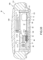
- FIG. 33 is a side section view schematically showing a radio-controlled timepiece according to a thirteenth embodiment of the invention.
- FIG. 34 is a side section view schematically showing a radio-controlled timepiece according to yet another variation of the invention.
- FIG. 35 is a side section view schematically showing a radio-controlled timepiece according to yet another variation of the invention.
- FIG. 1 is a front view of a radio-controlled timepiece as an example of an electronic timepiece with an internal antenna according to a preferred embodiment of the invention.
- a radio-controlled timepiece 1 is an analog timepiece with hands 11 , 12 , and 13 and a dial 14 , and is a timepiece that can receive long-wave standard time signals as external radio frequency information containing time information, and can correct the positions indicated by the hands 11 , 12 , and 13 based on the received time information.
- the radio-controlled timepiece 1 includes the hands 11 , 12 , and 13 , the dial 14 , a module 10 (see FIG. 2 ) including components for controlling an antenna 21 that receives the standard time signals and driving the hands 11 , 12 , and 13 , and an external case 100 that houses thereinside the hands 11 , 12 , and 13 , dial 14 , and module 10 .
- the dial 14 is preferably made from a non-electrically conductive material such as plastic or ceramic so that the dial 14 does not interfere with standard time signal waves entering the timepiece from the crystal side and signals can be received with good reception.
- the module 10 used in the radio-controlled timepiece 1 is described below with reference to FIG. 2 to FIG. 7 .
- FIG. 2 is a schematic plan view from the back cover side of the radio-controlled timepiece according to the first embodiment of the invention.
- FIG. 3 is a schematic block diagram of the radio-controlled timepiece according to the first embodiment of the invention.
- FIG. 4 is a schematic block diagram of the reception circuit unit of the radio-controlled timepiece according to the first embodiment of the invention.
- FIG. 5 is a side section view through the thickness of the radio-controlled timepiece according to the first embodiment of the invention.
- FIG. 6 is a section view through a position near the antenna in the radio-controlled timepiece according to the first embodiment of the invention.
- FIG. 7 is a front view of the base plate of the timekeeping module in the radio-controlled timepiece according to the first embodiment from the side facing the dial.
- the module 10 has a plastic module spacer 101 that is round when seen in plan view (see FIG. 5 ), and is secured by being press fit, for example, to the inside of the external case 100 .
- a plurality of bosses may be positioned projecting from the outside surface of the module spacer 101 so that when the module spacer 101 is housed in the external case 100 , the bosses contact the inside circumference surface of the external case 100 and hold the module spacer 101 in place.
- Assembled on the inside of the module spacer 101 in the module 10 are components including a circuit board 80 (see FIG. 5 ), the movement, a high capacity secondary power supply (storage battery) 72 forming a power supply 7 , an antenna 21 for receiving signals, and a base plate 102 that supports the movement and antenna 21 .
- the circuit board 80 is populated with devices including a reception chip 86 (see FIG. 2 ), a CPU 87 (see FIG. 2 ), and a reference oscillator 311 (see FIG. 3 ).
- the movement includes motors 411 and 421 that are part of the drive unit 4 , and a wheel train.
- the module 10 is housed in the casing 110 with the dial-side surface 103 of the base plate 102 facing the dial 14 substantially touching the solar cell 15 positioned on the back side of the dial 14 .
- the circuit devices positioned on the circuit board 80 include a reception processor 2 for processing the received signals, a drive control circuit unit 3 , a drive unit 4 for driving the hands, and a counter unit 6 for counting the time.
- the reception processor 2 includes the antenna 21 for receiving signals, a tuning circuit unit 22 composed of a capacitor and other components for tuning to the signal received by the antenna 21 , a reception processing circuit 23 that processes information received by the antenna 21 , and a time data storage circuit unit 24 that stores the time data processed by the reception processing circuit 23 .
- the tuning circuit unit 22 includes two capacitors 22 A and 22 B parallel connected to the antenna 21 with one capacitor 22 B connected to the antenna 21 through a switch 22 C.
- the frequency of the signal received by the antenna 21 can be changed by a frequency switching control signal that is output from the drive control circuit unit 3 and causes the switch 22 C to turn on or off.
- This enables switching and receiving long-wave standard time signals of two different frequencies, such as the 40-kHz signals that are transmitted by the standard time signal transmission station at Mount Otakadoya (for eastern Japan) and the 60-kHz signals that are transmitted by the transmission station at Mount Hagane (for western Japan) in Japan.
- the reception processing circuit 23 includes an amplifier circuit 231 , a bandpass filter 232 , a demodulation circuit 233 , an automatic gain control (AGC) circuit 234 , and a decoding circuit 235 .
- AGC automatic gain control
- the amplifier circuit 231 amplifies the long-wave standard time signal received by the antenna 21 .
- the bandpass filter 232 extracts the desired frequency component from the amplified long-wave standard time signal.
- the demodulation circuit 233 smoothes and demodulates the extracted long-wave standard time signal.
- the AGC circuit 234 controls the gain of the amplifier circuit 231 to keep the reception level of the long-wave standard time signal constant.
- the decoding circuit 235 then decodes and outputs the demodulated long-wave standard time signal.
- the time data that is received and signal processed by the reception processing circuit 23 is output to and stored by the time data storage circuit unit 24 as shown in FIG. 3 .
- the reception processing circuit 23 starts receiving time information based on a reception control signal output from the drive control circuit unit 3 according to a predetermined reception schedule or when reception is started unconditionally by operation of an external input device 8 .
- a pulse signal from the pulse synthesizing circuit 31 is input to the drive control circuit unit 3 .
- the pulse synthesizing circuit 31 frequency divides a reference pulse from the reference oscillator 311 , such as a crystal oscillator, to generate a clock pulse, and generates pulse signals of different pulse widths and timing from the reference pulse.
- the reference oscillator 311 is connected to the CPU 87 and produces a clock signal for the circuitry, and is located away from the antenna 21 because the clock signal frequency is near the frequency of the received long-wave standard time signal and produces noise if mixed with the signals received by the antenna 21 .
- the drive control circuit unit 3 outputs a seconds drive pulse signal PS 1 that is output once a second for driving the second hand, and an hour/minute drive pulse signal PS 2 that is output once a minute for driving the hour and minute hands, to the seconds drive circuit 41 and hour/minute drive circuit 42 .
- the drive circuits 41 and 42 drive the seconds motor 411 and hour/minute motor 421 , which are stepping motors, thus driving the second hand and the minute and hour hands that are connected to the motors 411 and 421 .
- the hands, dial, motors 411 and 421 , and drive circuits 41 and 42 thus form a time display for displaying the time. Note that the time display may also drive the hour hand, minute hand, and second hand using a single motor.
- the counter unit 6 includes a seconds counter circuit unit 61 for counting the seconds, and a hour/minute counter circuit unit 62 for counting the hour and minute.
- the seconds counter circuit unit 61 includes a seconds position counter 611 , a seconds time counter 612 , and a match detection circuit 613 .
- the seconds position counter 611 and seconds time counter 612 are both counters that loop at the 60 count, that is, every 60 seconds when a 1-Hz signal is input.
- the seconds position counter 611 counts the drive pulse signal (seconds drive pulse signal PS 1 ) that is supplied from the drive control circuit unit 3 to the seconds drive circuit 41 . More specifically, the position that is pointed to by the second hand is counted by counting the drive pulse signal that drives the second hand.
- the seconds time counter 612 normally counts the 1-Hz reference pulse (clock pulse) that is output from the drive control circuit unit 3 . If time data is received by the reception processor 2 , the counter is adjusted to match the seconds value in the received time data.
- the hour/minute counter circuit unit 62 similarly includes an hour/minute position counter 621 , an hour/minute time counter 622 , and a match detection circuit 623 .
- the hour/minute position counter 621 and hour/minute time counter 622 are both counters that loop when signals equal to 24 hours are input.
- the hour/minute position counter 621 counts the drive pulse signal (hour/minute drive pulse signal PS 2 ) that is supplied from the drive control circuit unit 3 to the hour/minute drive circuit 42 , and counts the positions that are pointed to by the hour hand and minute hand.
- the hour/minute time counter 622 normally counts a 1-Hz clock pulse that is output from the drive control circuit unit 3 . More precisely, the hour/minute time counter 622 increments 1 when sixty 1-Hz pulses are counted. If time data is received by the reception processor 2 , the counter is adjusted to match the hour and minute values in the received time data.
- the match detection circuits 613 and 623 detect if the counts of the position counters 611 and 621 and the counts of the time counters 612 and 622 match, and output a detection signal indicating whether or not the counts match to the drive control circuit unit 3 .
- the drive control circuit unit 3 continues outputting the drive pulse signals PS 1 and PS 2 until a match signal is input. If the 1-Hz reference signal from the drive control circuit unit 3 causes the count of the time counters 612 and 622 to change and a mismatch with the position counters 611 and 621 occurs during the normal timekeeping operation of the movement, the drive pulse signals PS 1 and PS 2 are output so that the hands move and the position counters 611 and 621 again match the time counters 612 and 622 . This operation keeps repeating and the movement is controlled as usual.
- the drive pulse signals PS 1 and PS 2 are output continuously and the hands are moved quickly and adjusted to the correct time until the counts of the position counters 611 and 621 and the time counters 612 and 622 match.
- the power supply 7 is formed with a high capacity secondary power supply 72 that is connected to a solar cell 15 adhesively affixed to the back cover side of the dial 14 (the side facing the module 10 ) and stores power produced by the solar cell 15 .
- the high capacity secondary power supply 72 may be a lithium ion battery or other type of secondary cell.
- a primary cell such as a silver oxide battery may alternatively be used as the power supply 7 .
- the high capacity secondary power supply 72 has a stainless steel case, and is positioned at a location near 3:00 o'clock separated from the antenna 21 inside the module 10 as shown in FIG. 2 in order to suppress its influence on antenna performance.
- a solar battery panel with magnetic permeability low enough to not affect standard time signal reception is used for the solar cell 15 .
- the external input device 8 used for external input has a crown 8 A and is used to set the time and start reception, for example.
- the antenna 21 has a magnetic core 211 , a coil 212 wound around the magnetic core 211 , and an antenna frame 213 that supports the magnetic core 211 .
- the antenna 21 When seen in plan view as shown in FIG. 2 , the antenna 21 has an elongated arc shape that is substantially concentric to the inside surface of the casing 110 forming the body of the external case 100 , and is positioned at the 9:00 o'clock position of a timepiece along the inside surface of the module spacer 101 .
- the magnetic core 211 has an elongated shape conforming to the length of the antenna 21 .
- the magnetic core 211 has a coil winding part 211 A in the middle around which the coil 212 is wound, and lead parts 211 B that extend from both ends of the coil winding part 211 A.
- the magnetic core 211 is made by adhesively stacking approximately 10 to 30 foil layers stamped or etched from a cobalt-based amorphous foil sheet (such as amorphous foil containing at least 50 wt % Co) as a magnetic foil member, and heat treating the foil layers by annealing, for example, to stabilize the magnetic characteristics.
- the magnetic core 211 is thus formed by stacking flat amorphous foil layers in the thickness direction of the timepiece.
- the magnetic core 211 is not limited to a layered amorphous foil construction, and may be made using a ferrite material that is shaped using a mold and then heat treated.
- the magnetic core 211 is supported by the antenna frame 213 .
- the antenna frame 213 has a recessed core-holding-magnetic-member seat 213 A corresponding to the shape of the magnetic core 211 .
- the magnetic core 211 is adhesively affixed in the core-holding-magnetic-member seat 213 A of the antenna frame 213 by an intervening adhesive layer formed by applying an adhesive, for example.
- a fastening part not shown is positioned on an end part of the antenna frame 213 , and this fastening part is affixed to the base plate 102 to secure the antenna 21 in the module 10 .
- the antenna frame 213 is fastened to the base plate 102 so that the open part of the core-holding-magnetic-member seat 213 A faces the base plate 102 . This enables locating the magnetic core 211 closer to the dial side, which is the side of the timepiece from which the standard time signal is received.
- the magnetic core 211 is also fastened to the base plate 102 so that a gap of a predetermined size is formed between the magnetic core 211 and the base plate 102 . This prevents damage to the antenna 21 because when the radio-controlled timepiece 1 is subject to shock the impact is not passed from the base plate 102 directly to the magnetic core 211 .
- the coil 212 must have an inductance of approximately 10 mH to receive long-wave standard time signals in the 40-77.5 kHz range.
- the coil 212 was made by wrapping several hundred winds of an approximately 0.1 ⁇ m diameter polyurethane-coated magnet wire around the core.
- a coil-overlapping area 104 that overlaps the coil 212 and a lead-overlapping area 105 that overlaps the lead part 211 B, are defined as shown in FIG. 7 .
- the antenna 21 and the reception chip 86 are connected by two leads. More specifically, the antenna 21 and the reception chip 86 are electrically connected by soldering the coil 212 at an end part of the antenna to the circuit board 80 . This enables outputting the standard time signal received by the antenna 21 to the reception processor 2 .
- the electrical connection may alternatively be made by attaching a flexible circuit made of polyimide, for example, to the antenna 21 , and fastening this circuit to the circuit board 80 with a screw.
- the amorphous foil member 140 is bonded as a magnetic member to the dial-side surface 103 of the base plate 102 facing the dial 14 .
- recessed magnetic member seats 102 A are formed in the dial-side surface 103 of the base plate 102 at positions that are outside of the coil-overlapping area 104 superposed on the coil 212 of the antenna 21 , and are partially within the pair of lead-overlapping areas 105 that are superposed on the pair of lead parts 211 B of the antenna 21 .
- These two amorphous foil members 140 are formed extending in the direction in which the lead parts 211 B project from the coil 212 (that is, away from the coil 212 ) when seen in plan view.
- the amorphous foil members 140 are larger in area than the lead-overlapping areas 105 .
- the amorphous foil members 140 are also bonded to the dial-side surface 103 through an intervening adhesive layer.
- This amorphous foil member 140 is a cobalt-based amorphous foil made of Co—Fe—Ni—B—Si, for example.
- the relative magnetic permeability of an amorphous foil member 140 made of a Co—Fe—Ni—B—Si cobalt-based amorphous foil, for example, is 20,000, and the permeability is significantly higher than the dial 14 and the solar cell 15 .
- Ambient magnetic flux lines therefore collect in the amorphous foil members 140 , the field strength rises, and more flux lines pass from the amorphous foil members 140 through the lead parts 211 B into the magnetic core 211 .
- a test sample was prepared with the amorphous foil members 140 positioned on the base plate 102 at locations superimposed on the coil-overlapping area 104 and lead-overlapping area 105 , and another sample was prepared with the amorphous foil members 140 not superimposed on the coil-overlapping area but superimposed on the lead-overlapping area.
- the reception sensitivity of the antenna 21 was then measured in both samples, and the results are shown in FIG. 8 .
- an improvement in reception sensitivity was not observed when the amorphous foil members 140 are located at positions superimposed on the coil-overlapping area. More specifically, when a part of the amorphous foil member 140 overlaps the coil-overlapping area 104 , the distance from the amorphous foil member 140 to the coil 212 becomes closer, magnetic flux lines collected in the coil 212 escape from the part of the amorphous foil members 140 overlapping the coil-overlapping area, reception sensitivity does not improve, and the desired effect of improving antenna performance is not achieved.
- the external case 100 includes the casing 110 , a crystal 120 attached to the dial side of the casing 110 , and a metal back cover 130 removably attached to the back side of the casing 110 (the side on the bottom).
- the casing 110 may be made of metal, such as stainless steel, brass, or titanium.
- the casing 110 in this embodiment of the invention is substantially cylindrical and the inside surface is substantially round when seen in plan view.
- a magnetic member for preventing eddy currents produced in a secondary magnetic path by the antenna 21 receiving radio waves may be positioned on the back cover 130 or casing 110 .
- an amorphous foil member 140 with higher permeability than the dial 14 and solar cell 15 is positioned in a radio-controlled timepiece 1 according to this first embodiment of the invention between the dial 14 and base plate 102 of the module 10 at a position not superposed to the coil-overlapping area 104 and superposed to the lead-overlapping area 105 .
- the amorphous foil members 140 can attract more magnetic flux lines and guide the magnetic flux lines into the lead parts 211 B, and thus more effectively collect magnetic flux lines in the antenna 21 . Furthermore, because the amorphous foil members 140 are not positioned in the coil-overlapping area, the magnetic flux lines collected by the amorphous foil members 140 do not escape into the coil 212 and can be concentrated in the lead parts 211 B of the magnetic core 211 . More magnetic flux lines therefore pass through the magnetic core 211 , the magnetic flux density increases, and the performance of the antenna 21 can be improved.
- the antenna 21 is preferably located near the dial 14 away from the back cover as described in the foregoing embodiment of the invention and amorphous foil members 140 are positioned between the dial 14 and the module 10 , further suppressing the production of eddy current in the secondary magnetic path produced at the antenna 21 and thus improving antenna characteristics.
- the amorphous foil members 140 can be positioned in this space without impinging on the space available for other parts while also assuring sufficient space for positioning the amorphous foil members 140 .
- the area of the amorphous foil members 140 can therefore be increased and flux collection can be improved.
- the amorphous foil members 140 are adhesively affixed to the magnetic member seats 102 A formed in the dial-side surface 103 of the base plate 102 . More specifically, because the circuit board 80 and the drive unit, motors, wheel train, high capacity secondary power supply 72 , and other parts of the movement are positioned on the back cover side of the base plate 102 in the module 10 , none of the movement parts are located on the dial-side surface 103 side of the base plate 102 . Sufficient area for positioning the amorphous foil members 140 can thus be assured, and the area of the amorphous foil members 140 can be increased. More magnetic flux lines can therefore be collected, the flux collection effect of the antenna 21 can be improved, and antenna performance can be improved.
- antenna performance such as the tuning frequency of the antenna 21
- the invention Compared with measuring the antenna performance after the radio-controlled timepiece 1 is assembled, the invention thus enables inspecting the antenna 21 and detecting defective antennas 21 at an earlier stage in the manufacturing process. Therefore, compared with measuring the performance of the antenna 21 after the radio-controlled timepiece 1 is assembled, the invention enables simplifying the manufacturing process and efficiently manufacturing the radio-controlled timepiece 1 .
- the antenna 21 and the amorphous foil members 140 must be precisely positioned to each other when installing the module 10 after installing the dial 14 in the casing 110 .
- the position of the antenna 21 on the base plate 102 is fixed with the foregoing configuration in which the amorphous foil members 140 are adhesively affixed to the base plate 102 , the amorphous foil member 140 and the antenna 21 can be easily positioned to each other. The manufacturing efficiency of the radio-controlled timepiece 1 can thus be further improved.
- An amorphous foil member 140 is used as the magnetic member in this embodiment of the invention.
- the permeability of this amorphous foil member 140 is significantly greater than the timepiece parts other than the magnetic core 211 of the antenna 21 , particularly the dial 14 , the solar cell 15 , the casing 110 , and the back cover 130 .
- Ambient magnetic flux lines can thus be efficiently gathered in the amorphous foil member 140 . More magnetic flux lines are thus input to the magnetic core 211 from the amorphous foil members 140 through the lead parts 211 B, the magnetic flux collection effect of the antenna 21 is improved, and antenna performance can be improved.
- the amorphous foil members 140 are formed extending in the same directions as the lead parts 211 B, and cover a larger area than the lead-overlapping area.
- More magnetic flux lines are thus gathered in the amorphous foil members 140 , and more magnetic flux lines are input to the lead parts 211 B.
- the flux density in the center of the magnetic core 211 is thus also increased, and reception sensitivity can be further improved.
- the amorphous foil members 140 are made of foil and are adhesively affixed using an adhesive layer.
- the thickness of the amorphous foil members 140 and the adhesive layer can be sufficiently reduced compared with the configuration of the related art that uses a magnetic sheet having an amorphous metal blended with a plastic sheet, and the amorphous foil members 140 can be easily positioned in the small gap between base plate 102 and the solar cell 15 that is adhesively affixed to the back side of the dial 14 .
- the thickness of the radio-controlled timepiece 1 is thus not increased and a good design can be achieved.
- FIG. 9 is a section view of a radio-controlled timepiece according to a second embodiment of the invention through a position near the lead part of the antenna.
- the radio-controlled timepiece 1 A has plural layers of the amorphous foil members 140 positioned on the base plate 102 in the first embodiment.
- a plurality of amorphous foil members 140 are layered on the base plate 102 of the radio-controlled timepiece 1 A according to the second embodiment of the invention at a position that is not superposed to the coil-overlapping area 104 and is superposed to the lead-overlapping area 105 as shown in FIG. 9 , thus forming an amorphous foil layer 141 .
- magnetic member seats 102 A are positioned on the dial-side surface 103 of the base plate 102 .
- the depth of this magnetic member seats 102 A is set appropriately according to the number of amorphous foil members 140 that are stacked so that when the amorphous foil layer 141 is formed the dial-side surface 103 of the base plate 102 and the surface of the amorphous foil layer 141 facing the dial 14 are substantially flush.
- These amorphous foil members 140 are bonded together by an adhesive layer formed from an adhesive, and are adhesively bonded to the base plate 102 through an intervening adhesive layer as described above in the first embodiment.
- an amorphous foil layer 141 of plural stacked amorphous foil members 140 is positioned on the dial-side surface 103 of the base plate 102 in the radio-controlled timepiece 1 A according to the second embodiment of the invention at a position not overlapping the coil-overlapping area 104 and overlapping at least a part of the lead-overlapping area 105 .
- this embodiment of the invention increases the thickness of the amorphous foil layer 141 so that even more magnetic flux lines can be collected and the magnetic flux collection effect can be further improved. The performance of the antenna 21 can thus be even further improved.
- the surface of the amorphous foil layer 141 facing the dial 14 can be formed substantially flush to the dial-side surface 103 of the base plate 102 . Therefore, when the module 10 is placed in the casing 110 , the gap between the solar cell 15 on the back cover side of the dial 14 and the base plate 102 can be reduced and a thin radio-controlled timepiece 1 A can be achieved.
- the distance between the amorphous foil layer 141 and the lead parts 211 B can be shortened, magnetic flux lines collected by the amorphous foil layer 141 can be desirably input to the lead parts 211 B, and the flux density passing through the center of the magnetic core 211 can be increased.
- the magnetic flux collection efficiency of the amorphous foil layer 141 can thus be improved and antenna performance can be improved.
- FIG. 10 is a section view through a position near the lead part of the antenna in a radio-controlled timepiece according to a third embodiment of the invention.
- the amorphous foil layer 141 is formed by stacking the amorphous foil members 140 on the dial-side surface 103 of the base plate 102 .
- the amorphous foil members 140 are stacked towards the lead part 211 B side.
- a through-hole 102 B communicating the dial-side surface 103 with the lead-facing surface 106 opposite the lead part 211 B is positioned in a part of the magnetic member seats 102 A within the lead-overlapping area 105 of the base plate 102 .
- the amorphous foil members 140 are positioned in the magnetic member seats 102 A.
- the amorphous foil members 140 form the magnetic flux collection unit of the invention.
- Amorphous foil members 140 A are then stacked toward the lead part 211 B from the surface of the amorphous foil member 140 that is adhesively affixed to the magnetic member seats 102 A and facing the through-hole 102 B.
- This amorphous foil layer 141 A forms the magnetic field output unit of the invention.
- a gap of a predetermined size is positioned between the surface of the amorphous foil layer 141 A facing the lead part 211 B and the lead part 211 B to prevent damage to the lead part 211 B and the amorphous foil layer 141 A. More particularly, if the lead part 211 B and the amorphous foil layer 141 A touch and the radio-controlled timepiece 1 B is subject to shock, vibration induced by the shock will cause the amorphous foil layer 141 A and lead part 211 B to collide and possibly be damaged. However, by providing a gap as described above, this collision caused by vibration can be avoided even if the timepiece is subject to shock, and damage to the lead part 211 B and amorphous foil layer 141 A can be prevented.
- an amorphous foil member 140 is positioned on the dial-side surface 103 of the base plate 102 in the radio-controlled timepiece 1 A according to the third embodiment of the invention at a position not overlapping the coil-overlapping area 104 and overlapping at least a part of the lead-overlapping area 105 .
- a through-hole 102 B communicating the dial-side surface 103 with the lead-facing surface 106 is also formed in the lead-overlapping area 105 of the base plate 102 , and amorphous foil members 140 A are stacked in this through-hole 102 B from the amorphous foil member 140 toward the lead part 211 B to form an amorphous foil layer 141 A.
- the resulting amorphous foil layer 141 A can thus desirably guide magnetic flux lines collected by the amorphous foil members 140 from the dial-side surface 103 of the base plate 102 to the lead-facing surface 106 side. Furthermore, because the amorphous foil layer 141 A is positioned proximally to the lead part 211 B, magnetic flux lines guided by the base plate 102 can be more efficiently input to the lead parts 211 B. This increases magnetic flux line input to the lead parts 211 B, increases the flux density of the magnetic core 211 , improves the flux collection effect, and further improves antenna performance.
- a gap of a predetermined size is positioned between the lead part 211 B and the amorphous foil layer 141 A. Therefore, even if impact is applied to the radio-controlled timepiece 1 B, vibration caused by the impact will not cause the lead parts 211 B and amorphous foil layer 141 A to collide, and damage can be prevented.
- FIG. 11 is a section view through a position near the lead part of the antenna in a radio-controlled timepiece according to a fourth embodiment of the invention.
- FIG. 12 is a plan view showing the side of the base plate facing the dial in the radio-controlled timepiece according to the fourth embodiment of the invention.
- the radio-controlled timepiece 1 C according to a fourth embodiment of the invention has a date display window not shown for displaying the date formed in the dial 14 and solar cell 15 , and therefore also has in the module 10 a date wheel 160 for displaying the date in the date display window.
- the date wheel 160 includes a tens-digit wheel 162 and a ones-digit wheel 161 .
- the tens-digit wheel 162 has tens-digit markers for 0, 1, 2, and 3 positioned at equal intervals around the outside edge on the side facing the dial 14 . Positioned around the outside edge of the ones-digit wheel 161 on the side facing the dial 14 in the following order are a group of markers displaying “1” to “9” for the first ten days of the month (the 1st to the 9th), a group of markers displaying “0” to “9” for the second ten days of the month (the 10th to the 19th), a group of markers displaying “0” to “9” for the third ten days of the month (the 20th to the 29th), and end-of-month markers “0” and “1” corresponding to the 30th and 31st.
- Drive power from the hour/minute motor 421 is speed-reduced and transferred to the ones-digit wheel 161 through a date wheel train that is configured to a predetermined gear ratio. This results in the ones-digit wheel 161 turning the distance of one marker in 24 hours, thereby advancing the date displayed in the date window one day, and turning one revolution in 31 days.
- the ones-digit wheel 161 also has a tens-digit wheel engaging unit not shown.
- the tens-digit wheel engaging unit engages the tens-digit wheel 162 and causes the tens-digit wheel 162 to advance one marker. This causes one of the tens digit markers on the tens-digit wheel 162 and one of the unit markers on the ones-digit wheel 161 of the date wheel 160 assembly to be displayed in the date display window, and the displayed date thus changes daily.
- the date wheel 160 described above is attached to the dial 14 side of the base plate 102 in the module 10 . More specifically, a gap 163 of a predetermined size is formed between the solar cell 15 and the base plate 102 in the module 10 of the radio-controlled timepiece 1 C, and the date wheel 160 is positioned in this gap 163 .
- the amorphous foil member 140 is then adhesively affixed in this gap 163 between the base plate 102 and solar cell 15 at a position that is not superposed to the coil-overlapping area 104 , is superposed to the lead-overlapping area 105 , and is outside the area occupied by the date wheel 160 .
- a magnetic member seat 102 A such as formed in the base plate 102 in the first to third embodiments is not formed in this embodiment of the invention, and the amorphous foil member 140 is adhesively affixed protruding from the dial-side surface 103 of the base plate 102 into this gap 163 .
- the module 10 in the radio-controlled timepiece 1 C includes a date wheel 160 for displaying the date in a date window formed in the dial 14 .
- This date wheel 160 is positioned in a gap 163 formed between the base plate 102 and the dial 14 .
- the amorphous foil member 140 is positioned protruding from the dial-side surface 103 of the base plate 102 into the gap 163 at a position that is not superposed to the coil-overlapping area or the date wheel 160 and is superposed with the lead-overlapping area 105 .
- the amorphous foil member 140 is positioned to use the gap 163 where the date wheel 160 is positioned effectively. It is therefore not necessary to form a magnetic member seat 102 A in the base plate 102 , an amorphous foil member 140 can be positioned with a simpler construction, and the performance of the antenna 21 can be improved.
- FIG. 13 is a front view of a radio-controlled timepiece as an example of an electronic timepiece with an internal antenna according to a fifth embodiment of the invention.
- a radio-controlled timepiece 1 D is an analog timepiece with hands 11 , 12 , and 13 and a dial 14 , and is a timepiece that can receive long-wave standard time signals as external radio frequency information containing time information, and can correct the positions indicated by the hands 11 , 12 , and 13 based on the received time information.
- the radio-controlled timepiece 1 includes the hands 11 , 12 , and 13 , the dial 14 , a module 10 including components for controlling an antenna 21 that receives the standard time signals and driving the hands 11 , 12 , and 13 , and an external case 100 that houses thereinside the hands 11 , 12 , and 13 , dial 14 , and module 10 .
- the module 10 used in the radio-controlled timepiece 1 D is described below with reference to FIG. 14 to FIG. 17 .
- FIG. 14 is a schematic plan view from the back cover side of the radio-controlled timepiece according to the fifth embodiment of the invention.
- FIG. 15 is a schematic block diagram of the radio-controlled timepiece according to the fifth embodiment of the invention.
- FIG. 16 is a schematic block diagram of the reception circuit unit of the radio-controlled timepiece according to the fifth embodiment of the invention.
- FIG. 17 is a side section view through the thickness of the radio-controlled timepiece according to the fifth embodiment of the invention.
- the module 10 has a plastic module spacer 101 that is round when seen in plan view.
- a plurality of bosses that contact the inside surface of the external case 100 are formed protruding radially on the side of the module spacer 101 , and these bosses are arranged around the inside circumference surface of the external case 100 .
- Gaps equal to the protruding height of the bosses are formed between the inside surface of the external case 100 and the side of the module spacer 101 in the areas (see FIG. 17 ) where these bosses are not formed around the entire circumference of the side of the module spacer 101 .
- the bosses positioned on the module spacer 101 touch the inside surface of the external case 100 and thus fix the position of the module 10 inside the external case 100 .
- Assembled on the inside of the module spacer 101 in the module 10 are components including a circuit board, the movement, and a high capacity secondary power supply (storage battery) 72 forming a power supply 7 .
- the circuit board 80 is populated with devices including a reception chip 86 , a CPU 87 , and a reference oscillator 311 (see FIG. 15 ).
- the movement includes motors 411 and 421 that are part of the drive unit 4 , and a wheel train.
- An antenna 21 for receiving signals is positioned proximally to the external case 100 .
- the circuit devices positioned on the circuit board include a reception processor 2 for processing the received signals, a drive control circuit unit 3 , a drive unit 4 for driving the hands, and a counter unit 6 for counting the time.
- the reception processor 2 includes the antenna 21 for receiving signals, a tuning circuit unit 22 composed of a capacitor and other components for tuning to the signal received by the antenna 21 , a reception processing circuit 23 that processes information received by the antenna 21 , and a time data storage circuit unit 24 that stores the time data processed by the reception processing circuit 23 .
- the tuning circuit unit 22 includes two capacitors 22 A and 22 B parallel connected to the antenna 21 with one capacitor 22 B connected to the antenna 21 through a switch 22 C.
- the frequency of the signal received by the antenna 21 can be changed by a frequency switching control signal that is output from the drive control circuit unit 3 and causes the switch 22 C to turn on or off.
- This enables switching and receiving long-wave standard time signals of two different frequencies, such as the 40-kHz signals that are transmitted by the standard time signal transmission station at Mount Otakadoya (for eastern Japan) and the 60-kHz signals that are transmitted by the transmission station at Mount Hagane (for western Japan) in Japan.
- the reception processing circuit 23 includes an amplifier circuit 231 , a bandpass filter 232 , a demodulation circuit 233 , an automatic gain control (AGC) circuit 234 , and a decoding circuit 235 .
- AGC automatic gain control
- the amplifier circuit 231 amplifies the long-wave standard time signal received by the antenna 21 .
- the bandpass filter 232 extracts the desired frequency component from the amplified long-wave standard time signal.
- the demodulation circuit 233 smoothes and demodulates the extracted long-wave standard time signal.
- the AGC circuit 234 controls the gain of the amplifier circuit 231 to keep the reception level of the long-wave standard time signal constant.
- the decoding circuit 235 then decodes and outputs the demodulated long-wave standard time signal.
- the time data that is received and signal processed by the reception processing circuit 23 is output to and stored by the time data storage circuit unit 24 as shown in FIG. 15 .
- the reception processing circuit 23 starts receiving time information based on a reception control signal output from the drive control circuit unit 3 according to a predetermined reception schedule or when reception is started unconditionally by operation of an external input device 8 .
- a pulse signal from the pulse synthesizing circuit 31 is input to the drive control circuit unit 3 .
- the pulse synthesizing circuit 31 frequency divides a reference pulse from the reference oscillator 311 , such as a crystal oscillator, to generate a clock pulse, and generates pulse signals of different pulse widths and timing from the reference pulse.
- the reference oscillator 311 is connected to the CPU 87 and produces a clock signal for the circuitry, and is located away from the antenna 21 because the clock signal frequency is near the frequency of the received long-wave standard time signal and produces noise if mixed with the signals received by the antenna 21 .
- the drive control circuit unit 3 outputs a seconds drive pulse signal PS 1 that is output once a second for driving the second hand, and an hour/minute drive pulse signal PS 2 that is output once a minute for driving the hour and minute hands, to the seconds drive circuit 41 and hour/minute drive circuit 42 to drive the hands.
- the drive circuits 41 and 42 drive the seconds motor 411 and hour/minute motor 421 , which are stepping motors that are driven by pulse signals from the corresponding drive circuits 41 and 42 , and thus drive the second hand and the minute and hour hands that are connected to the motors 411 and 421 .
- the hands, dial, motors 411 and 421 , and drive circuits 41 and 42 thus form a time display for displaying the time. Note that the time display may also drive the hour hand, minute hand, and second hand using a single motor.
- the counter unit 6 includes a seconds counter circuit unit 61 for counting the seconds, and a hour/minute counter circuit unit 62 for counting the hour and minute.
- the seconds counter circuit unit 61 includes a seconds position counter 611 , a seconds time counter 612 , and a match detection circuit 613 .
- the seconds position counter 611 and seconds time counter 612 are both counters that loop at the 60 count, that is, every 60 seconds when a 1-Hz signal is input.
- the seconds position counter 611 counts the drive pulse signal (seconds drive pulse signal PS 1 ) that is supplied from the drive control circuit unit 3 to the seconds drive circuit 41 . More specifically, the position that is pointed to by the second hand is counted by counting the drive pulse signal that drives the second hand.
- the seconds time counter 612 normally counts the 1-Hz reference pulse (clock pulse) that is output from the drive control circuit unit 3 . If time data is received by the reception processor 2 , the counter is adjusted to match the seconds value in the received time data.
- the hour/minute counter circuit unit 62 similarly includes an hour/minute position counter 621 , an hour/minute time counter 622 , and a match detection circuit 623 .
- the hour/minute position counter 621 and hour/minute time counter 622 are both counters that loop when signals equal to 24 hours are input.
- the hour/minute position counter 621 counts the drive pulse signal (hour/minute drive pulse signal PS 2 ) that is supplied from the drive control circuit unit 3 to the hour/minute drive circuit 42 , and counts the positions that are pointed to by the hour hand and minute hand.
- the hour/minute time counter 622 normally counts a 1-Hz clock pulse that is output from the drive control circuit unit 3 . More precisely, the hour/minute time counter 622 increments 1 when sixty 1-Hz pulses are counted. If time data is received by the reception processor 2 , the counter is adjusted to match the hour and minute values in the received time data.
- the match detection circuits 613 and 623 detect if the counts of the position counters 611 and 621 and the counts of the time counters 612 and 622 match, and output a detection signal indicating whether or not the counts match to the drive control circuit unit 3 .
- the drive control circuit unit 3 continues outputting the drive pulse signals PS 1 and PS 2 until a match signal is input. If the 1-Hz reference signal from the drive control circuit unit 3 causes the count of the time counters 612 and 622 to change and a mismatch with the position counters 611 and 621 occurs during the normal timekeeping operation of the movement, the drive pulse signals PS 1 and PS 2 are output so that the hands move and the position counters 611 and 621 again match the time counters 612 and 622 . This operation keeps repeating and the movement is controlled as usual.
- the drive pulse signals PS 1 and PS 2 are output continuously and the hands are moved quickly and adjusted to the correct time until the counts of the position counters 611 and 621 and the time counters 612 and 622 match.
- a power supply 7 includes a generating device 71 and the high capacity secondary power supply 72 .
- the generating device 71 is a power generator formed by a self-winding generator or a solar cell (solar generator).
- the high capacity secondary power supply 72 stores power generated by the generating device 71 .
- the high capacity secondary power supply 72 may be a lithium ion battery or other type of secondary cell.
- a primary cell such as a silver oxide battery may alternatively be used as the power supply 7 . Note that because the high capacity secondary power supply 72 has a stainless steel case, it is positioned in the module 10 at a position separated from the antenna 21 at a location near 3:00 o'clock as shown in FIG. 14 in order to suppress its influence on antenna performance.
- the external input device 8 used as an external input has a crown and is used to set the time and start reception, for example.
- the antenna 21 is located near the 9:00 o'clock position of the timepiece dial conforming substantially to the inside surface of the module spacer 101 .
- the antenna 21 has a magnetic core 211 and a coil 212 wound around the magnetic core 211 .
- the magnetic core 211 is substantially square in section as shown in FIG. 17 . As shown in FIG. 14 , the magnetic core 211 has a straight coil winding part 211 A around which the coil 212 is wound, and lead parts 211 B that extend from both ends of the coil winding part 211 A conforming substantially to the inside surface of the casing 110 that forms the body of the external case 100 .
- the magnetic core 211 is made by adhesively stacking approximately 10 to 30 foil layers stamped or etched from a cobalt-based amorphous foil sheet (such as amorphous foil containing at least 50 wt % Co), and heat treating the foil layers by annealing, for example, to stabilize the magnetic characteristics.
- the magnetic core 211 is thus formed by stacking flat amorphous foil layers in the thickness direction of the timepiece.
- the magnetic core 211 is not limited to a layered amorphous foil construction, and may be made using a ferrite material that is shaped using a mold and then heat treated.
- the coil 212 must have an inductance of approximately 10 mH to receive long-wave standard time signals in the 40-77.5 kHz range.
- the coil 212 was made by wrapping several hundred winds of an approximately 0.1 ⁇ m diameter polyurethane-coated magnet wire around the core.
- the antenna 21 and the reception chip 86 are connected by two leads. More specifically, the antenna 21 and the reception chip 86 are electrically connected by soldering the coil 212 at an end part of the antenna to the circuit board. This enables outputting the standard time signal received by the antenna 21 to the reception processor 2 .
- the electrical connection may alternatively be made by attaching a flexible circuit made of polyimide, for example, to the antenna 21 , and fastening this circuit to the circuit board with a screw.
- the external case 100 includes the casing 110 , a crystal 120 attached to the dial side of the casing 110 , and a metal back cover 130 attached to the back side of the casing 110 (the side on the bottom).
- the casing 110 is made of metal, such as stainless steel, brass, or titanium.
- the casing 110 in this embodiment of the invention is substantially cylindrical and the inside surface is substantially round when seen in plan view.
- FIG. 18 is a plan view showing the configuration of the inside surface of the back cover in the fifth embodiment of the invention.
- the back cover 130 includes a disc-shaped round part 131 that is slightly larger in diameter than the inside surface of the casing 110 , and four screw flanges 132 projecting to the outside radially from the round part 131 .
- Each screw flange 132 has a screw hole 133 through which a screw can pass.
- the back cover 130 is located in a predetermined position on the bottom of the casing 110 , and then fastened to the casing 110 with screws screwed through the screw hole 133 in each of the screw flanges 132 into the bottom of the casing 110 .
- an amorphous foil member 140 is adhesively affixed as a metal magnetic foil member to the inside surface of the back cover 130 (the surface facing the module 10 ).
- this amorphous foil member 140 is positioned on the inside surface of the back cover 130 at positions that are not superposed to the coil-facing area 134 (coil-overlapping area) opposite the coil winding part 211 A, and are partially superposed to the pair of lead-facing areas 135 (lead-overlapping areas) opposite the lead parts 211 B.
- the pair of amorphous foil members 140 are formed extending in the direction in which the lead parts 211 B project (the direction away from the coil 212 ) when seen in plan view.
- These amorphous foil members 140 are adhesively affixed to the back cover 130 through an intervening adhesive layer.
- This amorphous foil member 140 is a cobalt-based amorphous foil made of Co—Fe—Ni—B—Si, for example.
- the relative magnetic permeability of an amorphous foil member 140 made of a Co—Fe—Ni—B—Si cobalt-based amorphous foil, for example, is 20 , 000 .
- the relative magnetic permeability of a back cover 130 made of stainless steel is 1.4, 1.0 when made of brass, and 1.0001 when made of titanium.
- the magnetic permeability of the amorphous foil member 140 is thus significantly greater than the metal from which the back cover 130 is made. Ambient magnetic flux lines are thus collected in the amorphous foil member 140 , and the magnetic field becomes stronger. As a result, more magnetic flux lines pass from the lead parts 211 B opposite the amorphous foil members 140 through the magnetic core, and the magnetic flux density increases.
- the electrical conductivity of the amorphous foil members 140 is lower than the metal used in the back cover 130 , less eddy current is produced by the magnetic flux lines passing through the amorphous foil members 140 than when the magnetic flux lines pass through the back cover 130 .
- the radio-controlled timepiece 1 D has a pair of amorphous foil members 140 positioned on the inside surface of the back cover 130 at a position that is not superposed to the coil-facing area 134 opposite the antenna 21 and is superposed to part of the lead-facing areas 135 .
- the magnetic flux lines collected by the amorphous foil members 140 pass from the lead parts 211 B into the magnetic core 211 , and the flux collection effect of the antenna can be improved.
- the reception voltage of the antenna 21 is generally proportional to the flux density in the center of the magnetic core 211 , the reception sensitivity can also be increased by thus improving the flux collection effect, and an antenna 21 with good reception sensitivity can be achieved.
- the size of the radio-controlled timepiece 1 D is not increased as a result of a larger antenna 21 .
- the flux collection effect can therefore be improved while affording a pleasing design characteristic.
- the amorphous foil members 140 do not directly touch the antenna 21 , damage caused by shock-induced vibration can be prevented when the radio-controlled timepiece 1 D is subjected to shock. A separate member for protecting the amorphous foil members 140 is therefore also not necessary.
- the radio-controlled timepiece 1 D described above thus affords a thinner, smaller timepiece having a simple construction while also achieving good antenna 21 performance.
- An amorphous foil member 140 is used as the metal magnetic foil member.
- the magnetic permeability of this amorphous foil member 140 is significantly higher than the casing 110 , back cover 130 , and other timepiece parts other than the magnetic core 211 of the antenna 21 .
- magnetic flux around the amorphous foil members 140 can be efficiently collected, the magnetic flux lines input from the amorphous foil members 140 through the lead parts 211 B to the magnetic core 211 can be increased, the flux collection effect of the antenna 21 is thus improved, and antenna performance can be further improved.
- the amorphous foil members 140 are formed extending from the lead-facing areas 135 opposite the lead parts 211 B in the direction away from the coil-facing area 134 .
- the amorphous foil members 140 are thus formed in an area larger than the lead-facing areas 135 .
- the amorphous foil members 140 are also made of foil and are adhesively affixed by an adhesive layer formed by applying an adhesive coating. As a result, the thickness of the amorphous foil members 140 and the adhesive layer can be sufficiently reduced compared with the configuration of the related art that uses a magnetic sheet having an amorphous metal blended with a plastic sheet, and the size of the gap between the back cover 130 and module 10 can be reduced. The thickness of the radio-controlled timepiece 1 D is thus not increased and a good design can be achieved.
- FIG. 19 shows the configuration of the back cover of a radio-controlled timepiece according to a sixth embodiment of the invention.
- This sixth embodiment changes the shape of the amorphous foil members 140 positioned on the back cover 130 in the fifth embodiment.
- the amorphous foil members 140 are positioned on the back cover 130 of the radio-controlled timepiece according to the sixth embodiment of the invention opposite the pair of lead-facing areas 135 in an area superposed to substantially the entire area covered by the lead-facing areas 135 and not superposed to the coil-facing area 134 .
- These amorphous foil members 140 extend on the surface of the back cover 130 opposite the inside surface of the casing 110 to near the center line of the timepiece (a line connecting the 12:00 o'clock and 6:00 o'clock positions of the dial).
- These amorphous foil member 140 can be made from the same amorphous metal that is used for the amorphous foil members 140 in the fifth embodiment of the invention, and a cobalt-based amorphous metal is used in this embodiment.
- the size of the extension and the area of the amorphous foil members 140 are not limited to the foregoing. As shown in FIG. 20 , for example, the amorphous foil members 140 may be positioned covering the larger part of the 12:00 o'clock and 6:00 o'clock regions on opposite sides of areas extended from the coil-facing area 134 . Further alternatively, the pair of amorphous foil members 140 may be located in any positions where the amorphous foil members 140 are not superposed to the coil-facing area 134 and are superposed to the pair of lead-facing areas 135 , and the amorphous foil members 140 do not touch each other.
- This configuration increases the area of the amorphous foil members 140 and improves magnetic flux collection, but magnetic flux lines entering the amorphous foil members 140 at positions relatively distant to the lead-facing areas 135 opposite the lead parts 211 B are simply dispersed. Therefore, forming the amorphous foil members 140 in positions proximal to the center line of the timepiece as shown in FIG. 19 enables most efficiently collecting magnetic flux lines that can enter the lead parts 211 B.
- the amorphous foil members 140 are positioned on the inside surface of the back cover 130 extending substantially along the inside surface of the casing from a position that is not superposed to the coil-facing area 134 and is superposed to substantially the entire area occupied by the lead-facing areas 135 to a position near the center line of the timepiece.
- the amorphous foil member 140 covers a larger area than the amorphous foil member 140 in the fifth embodiment, and thus further improves flux collection. Furthermore, because the magnetic flux lines collected by the amorphous foil member 140 are input to substantially the entire area of the lead parts 211 B, more magnetic flux lines enter the magnetic core 211 from the lead parts 211 B, and the reception sensitivity of the antenna 21 can be further improved.
- a radio-controlled timepiece according to a seventh embodiment of the invention is described next with reference to the accompanying figures.
- FIG. 21 is a side section view of a radio-controlled timepiece according to a seventh embodiment of the invention.
- the radio-controlled timepiece 1 D according to the fifth embodiment described above has a single amorphous foil member 140 adhesively affixed to the back cover 130 opposite each of the pair of lead-facing areas 135 .
- a plurality of amorphous foil members 140 are stacked together on the back cover 130 to form an amorphous foil layer 141 opposite each of the pair of lead-facing areas 135 .
- the amorphous foil layers 141 are formed so that there is a gap of approximately 1 mm, for example, between the top of the amorphous foil layer 141 (the surface facing the module 10 ) and the module 10 .
- an amorphous foil layer 141 composed of stacked amorphous foil members 140 is formed in the radio-controlled timepiece 1 E according to this seventh embodiment of the invention at a position on the inside surface of the back cover 130 that does not overlap the coil-facing area 134 opposite the coil winding part 211 A and overlaps at least a part of the lead-facing areas 135 opposite the lead parts 211 B.
- the thickness of the amorphous foil layer 141 is thus greater than a configuration having a single amorphous foil member 140 affixed, more magnetic flux lines can therefore be collected, and the flux collection effect can be improved. Furthermore, because the distance between the amorphous foil layer 141 and the lead parts 211 B is smaller, magnetic flux lines collected by the amorphous foil layer 141 are desirably input to the lead parts 211 B, and the flux density passing through the center of the magnetic core 211 can be increased. The flux collection effect of the amorphous foil layer 141 can therefore be improved, and the reception sensitivity of the antenna 21 can be increased.
- a small gap is also formed between the top of the amorphous foil layer 141 and the module 10 .
- the amorphous foil layer 141 will not contact the module 10 , and damage to the amorphous foil layer 141 can be prevented.
- a radio-controlled timepiece according to an eighth embodiment of the invention is described next with reference to the accompanying figures.
- FIG. 22 is a side section view of a radio-controlled timepiece according to an eighth embodiment of the invention.
- the amorphous foil members 140 are stacked directly on the inside surface of the back cover 130 to form the amorphous foil layer 141 .
- a plastic sheet 142 is adhesively affixed as a non-conductive member to the inside surface of the back cover 130 , and the amorphous foil members 140 are layered on top of this plastic sheet to form an amorphous foil layer 143 .
- amorphous foil member 140 is shown layered on top of the plastic sheet 142 , but the invention is not so limited and a plurality of amorphous foil members 140 may be laminated together.
- the position where this amorphous foil layer 143 is formed is the same site as in the seventh embodiment, that is, a position where there is no overlap with the coil-facing area 134 and superposed to at least a part of the lead-facing areas 135 .
- plastic sheet is not limited to being affixed only at the position where the amorphous foil members 140 are stacked, and may be applied over the entire inside surface of the back cover 130 , for example.
- a plastic sheet 142 is affixed to the inside surface of the back cover 130 , and the amorphous foil member 140 is laminated on top of the plastic sheet 142 to form the amorphous foil layer 143 .
- the magnetic flux lines produced when signals are received by the antenna 21 thus do not flow from the amorphous foil member 140 to the back cover 130 , and the production of eddy current in the back cover 130 can be more effectively suppressed. Furthermore, if the radio-controlled timepiece 1 F is subject to shock, the plastic sheet 142 acts as a damper so that stress is not applied directly from the back cover 130 to the amorphous foil member 140 . As a result, impact damage to the amorphous foil member 140 can also be prevented.
- the amorphous foil member 140 can be positioned proximally to the lead parts 211 B as described in the seventh embodiment, the flux collection effect of the antenna 21 can be improved and good antenna performance can be achieved.
- FIG. 23 is a front view of a radio-controlled timepiece as an example of an electronic timepiece with an internal antenna according to a ninth embodiment of the invention.
- a radio-controlled timepiece 1 G is an analog timepiece with hands 11 , 12 , and 13 and a dial 14 , and is a timepiece that can receive long-wave standard time signals as external radio frequency information containing time information, and can correct the positions indicated by the hands 11 , 12 , and 13 based on the received time information.
- the radio-controlled timepiece 1 G includes the hands 11 , 12 , and 13 , the dial 14 , a module 10 (see FIG. 24 ) including components for controlling an antenna 21 that receives the standard time signals and driving the hands 11 , 12 , and 13 , and an external case 100 that houses within the hands 11 , 12 , and 13 , dial 14 , and module 10 .
- the dial 14 is preferably made from a non-electrically conductive material such as plastic or ceramic so that the dial 14 does not interfere with standard time signal waves entering the timepiece from the crystal side and signals can be received with good reception.
- the module 10 used in the radio-controlled timepiece 1 G is described below with reference to FIG. 24 to FIG. 28 .
- FIG. 24 is a plan view showing the inside of a radio-controlled timepiece according to a ninth embodiment of the invention from the back cover side with the circuit board removed.
- FIG. 25 is a plan view showing the inside of a radio-controlled timepiece according to a ninth embodiment of the invention from the back cover side with the circuit board installed.
- FIG. 26 is a side section view through the thickness of a radio-controlled timepiece according to the ninth embodiment of the invention.
- FIG. 27 is a schematic block diagram showing the configuration of a radio-controlled timepiece according to the ninth embodiment of the invention.
- FIG. 28 is a block diagram showing the configuration of the reception circuit unit in a radio-controlled timepiece according to the ninth embodiment of the invention.
- the module 10 has a plastic module spacer 101 that is round when seen in plan view (see FIG. 26 ), and is secured by being press fit, for example, to the inside of the external case 100 .
- a plurality of bosses may be positioned projecting from the outside surface of the module spacer 101 so that when the module spacer 101 is housed in the external case 100 , the bosses contact the inside circumference surface of the external case 100 and hold the module spacer 101 in place.
- Assembled on the inside of the module spacer 101 in the module 10 are components including a circuit board 80 , the movement, a high capacity secondary power supply (storage battery) 72 forming a power supply 7 , and an antenna 21 for receiving signals.
- the circuit board 80 is populated with devices including a reception chip 86 , a CPU 87 , and a reference oscillator 311 .
- the movement includes motors 411 and 421 that are part of the drive unit 4 , and a wheel train.
- the module spacer 101 of the module 10 in this embodiment is substantially container shaped, and the circuit board 80 is fastened by, for example, being press fit to the back cover 130 side of the module spacer 101 .
- the module 10 is then held in the external case 100 so that the circuit board 80 faces the back cover 130 .
- the antenna 21 is located near the 9:00 o'clock position of the timepiece dial conforming substantially to the inside surface of the module spacer 101 .
- the antenna 21 has a magnetic core 211 and a coil 212 wound around the magnetic core 211 .
- the magnetic core 211 is substantially square in section as shown in FIG. 26 . As shown in FIG. 24 , the magnetic core 211 has a straight coil winding part 211 A around which the coil 212 is wound, and lead parts 211 B that extend from both ends of the coil winding part 211 A conforming substantially to the inside surface of the casing 110 that forms the body of the external case 100 .
- the magnetic core 211 is made by adhesively stacking approximately 10 to 30 foil layers stamped or etched from a cobalt-based amorphous foil sheet (such as amorphous foil containing at least 50 wt % Co), and heat treating the foil layers by annealing, for example, to stabilize the magnetic characteristics.
- the magnetic core 211 is thus formed by stacking flat amorphous foil layers in the thickness direction of the timepiece.
- the magnetic core 211 is not limited to a layered amorphous foil construction, and may be made using a ferrite material that is shaped using a mold and then heat treated.
- the coil 212 must have an inductance of approximately 10 mH to receive long-wave standard time signals in the 40-77.5 kHz range.
- the coil 212 was made by wrapping several hundred winds of an approximately 0.1 ⁇ m diameter polyurethane-coated magnet wire around the core.
- an area superposed on the coil 212 when the radio-controlled timepiece 1 G is seen in plan view from the crystal or back cover side is defined as a coil-overlapping area 83 .
- the area superposed on the lead parts 211 B in the same view is defined as a lead-overlapping area 84 .
- the antenna 21 and the reception chip 86 described below positioned on the circuit board 80 are connected by two leads. More specifically, the antenna 21 and the reception chip 86 are electrically connected by soldering the coil 212 at an end part of the antenna to the circuit board. This enables outputting the standard time signal received by the antenna 21 to the reception processor 2 .
- the electrical connection may alternatively be made by attaching a flexible circuit made of polyimide, for example, to the antenna 21 , and fastening this circuit to the circuit board 80 with a screw.
- the circuit board 80 is described next with reference to the figures.
- the circuit devices positioned on the circuit board 80 include a reception processor 2 for processing the received signals, a drive control circuit unit 3 , a drive unit 4 for driving the hands, and a counter unit 6 for counting the time.
- the reception processor 2 includes the antenna 21 for receiving signals, a tuning circuit unit 22 composed of a capacitor and other components for tuning to the signal received by the antenna 21 , a reception processing circuit 23 that processes information received by the antenna 21 , and a time data storage circuit unit 24 that stores the time data processed by the reception processing circuit 23 .
- the tuning circuit unit 22 includes two capacitors 22 A and 22 B parallel connected to the antenna 21 with one capacitor 22 B connected to the antenna 21 through a switch 22 C.
- the frequency of the signal received by the antenna 21 can be changed by a frequency switching control signal that is output from the drive control circuit unit 3 and causes the switch 22 C to turn on or off.
- This enables switching and receiving long-wave standard time signals of two different frequencies, such as the 40-kHz signals that are transmitted by the standard time signal transmission station at Mount Otakadoya (for eastern Japan) and the 60-kHz signals that are transmitted by the transmission station at Mount Hagane (for western Japan) in Japan.
- the reception processing circuit 23 includes an amplifier circuit 231 , a bandpass filter 232 , a demodulation circuit 233 , an automatic gain control (AGC) circuit 234 , and a decoding circuit 235 .
- AGC automatic gain control
- the amplifier circuit 231 amplifies the long-wave standard time signal received by the antenna 21 .
- the bandpass filter 232 extracts the desired frequency component from the amplified long-wave standard time signal.
- the demodulation circuit 233 smoothes and demodulates the extracted long-wave standard time signal.
- the AGC circuit 234 controls the gain of the amplifier circuit 231 to keep the reception level of the long-wave standard time signal constant.
- the decoding circuit 235 then decodes and outputs the demodulated long-wave standard time signal.
- the time data that is received and signal processed by the reception processing circuit 23 is output to and stored by the time data storage circuit unit 24 as shown in FIG. 27 .
- the reception processing circuit 23 starts receiving time information based on a reception control signal output from the drive control circuit unit 3 according to a predetermined reception schedule or when reception is started unconditionally by operation of an external input device 8 .
- a pulse signal from the pulse synthesizing circuit 31 is input to the drive control circuit unit 3 .
- the pulse synthesizing circuit 31 frequency divides a reference pulse from the reference oscillator 311 , such as a crystal oscillator, to generate a clock pulse, and generates pulse signals of different pulse widths and timing from the reference pulse.
- the reference oscillator 311 is connected to the CPU 87 and produces a clock signal for the circuitry, and is located away from the antenna 21 because the clock signal frequency is near the frequency of the received long-wave standard time signal and produces noise if mixed with the signals received by the antenna 21 .
- the drive control circuit unit 3 outputs a seconds drive pulse signal PS 1 that is output once a second for driving the second hand, and an hour/minute drive pulse signal PS 2 that is output once a minute for driving the hour and minute hands, to the seconds drive circuit 41 and hour/minute drive circuit 42 .
- the drive circuits 41 and 42 drive the seconds motor 411 and hour/minute motor 421 , which are stepping motors, thus driving the second hand and the minute and hour hands that are connected to the motors 411 and 421 .
- the hands, dial, motors 411 and 421 , and drive circuits 41 and 42 thus form a time display for displaying the time. Note that the time display may also drive the hour hand, minute hand, and second hand using a single motor.
- the counter unit 6 includes a seconds counter circuit unit 61 for counting the seconds, and a hour/minute counter circuit unit 62 for counting the hour and minute.
- the seconds counter circuit unit 61 includes a seconds position counter 611 , a seconds time counter 612 , and a match detection circuit 613 .
- the seconds position counter 611 and seconds time counter 612 are both counters that loop at the 60 count, that is, every 60 seconds when a 1-Hz signal is input.
- the seconds position counter 611 counts the drive pulse signal (seconds drive pulse signal PS 1 ) that is supplied from the drive control circuit unit 3 to the seconds drive circuit 41 . More specifically, the position that is pointed to by the second hand is counted by counting the drive pulse signal that drives the second hand.
- the seconds time counter 612 normally counts the 1-Hz reference pulse (clock pulse) that is output from the drive control circuit unit 3 . If time data is received by the reception processor 2 , the counter is adjusted to match the seconds value in the received time data.
- the hour/minute counter circuit unit 62 similarly includes an hour/minute position counter 621 , an hour/minute time counter 622 , and a match detection circuit 623 .
- the hour/minute position counter 621 and hour/minute time counter 622 are both counters that loop when signals equal to 24 hours are input.
- the hour/minute position counter 621 counts the drive pulse signal (hour/minute drive pulse signal PS 2 ) that is supplied from the drive control circuit unit 3 to the hour/minute drive circuit 42 , and counts the positions that are pointed to by the hour hand and minute hand.
- the hour/minute time counter 622 normally counts a 1-Hz clock pulse that is output from the drive control circuit unit 3 . More precisely, the hour/minute time counter 622 increments 1 when sixty 1-Hz pulses are counted. If time data is received by the reception processor 2 , the counter is adjusted to match the hour and minute values in the received time data.
- the match detection circuits 613 and 623 detect if the counts of the position counters 611 and 621 and the counts of the time counters 612 and 622 match, and output a detection signal indicating whether or not the counts match to the drive control circuit unit 3 .
- the drive control circuit unit 3 continues outputting the drive pulse signals PS 1 and PS 2 until a match signal is input. If the 1-Hz reference signal from the drive control circuit unit 3 causes the count of the time counters 612 and 622 to change and a mismatch with the position counters 611 and 621 occurs during the normal timekeeping operation of the movement, the drive pulse signals PS 1 and PS 2 are output so that the hands move and the position counters 611 and 621 again match the time counters 612 and 622 . This operation keeps repeating and the movement is controlled as usual.
- the drive pulse signals PS 1 and PS 2 are output continuously and the hands are moved quickly and adjusted to the correct time until the counts of the position counters 611 and 621 and the time counters 612 and 622 match.
- the circuit elements such as the wiring pattern connecting the reception processor 2 , drive control circuit unit 3 , drive unit 4 , counter unit 6 , and other devices on the circuit board 80 are positioned on the antenna-facing surface 81 of the circuit board 80 on the side facing the antenna 21 described below at a position that is not opposite the antenna 21 . More specifically, because the effect of the electrical operation of these various circuit elements on the magnetic field can affect the performance of the antenna 21 , these circuit elements are positioned at a position separated from the antenna 21 as shown in FIG. 24 to avoid a drop in antenna performance.
- An amorphous foil member 140 is also adhesively affixed as a magnetic member on the antenna-facing surface 81 of the circuit board 80 opposite the antenna 21 as shown in FIG. 25 and FIG. 26 .
- amorphous foil members 140 are adhesively affixed to the back cover side 82 of the circuit board 80 facing the back cover 130 at positions that are outside of the coil-overlapping area 83 superposed on the coil 212 of the antenna 21 , and are partially within the pair of lead-overlapping areas 84 that are superposed on the pair of lead parts 211 B of the antenna 21 .
- These two amorphous foil members 140 are formed extending in the direction in which the lead parts 211 B project from the coil 212 (that is, away from the coil 212 ) when seen in plan view.
- the amorphous foil members 140 are larger in area than the lead-overlapping areas 84 .
- the amorphous foil members 140 are also bonded to the back cover side 82 through an intervening adhesive layer not shown formed by applying adhesive.
- This amorphous foil member 140 is a cobalt-based amorphous foil made of Co—Fe—Ni—B—Si, for example.
- the relative magnetic permeability of an amorphous foil member 140 made of a Co—Fe—Ni—B—Si cobalt-based amorphous foil, for example, is 20,000, and the permeability is significantly higher than the circuit board 80 .
- Ambient magnetic flux lines therefore collect in the amorphous foil members 140 , the field strength rises, and more flux lines pass from the amorphous foil members 140 through the lead parts 211 B into the magnetic core 211 .
- a test sample was prepared with the amorphous foil members 140 positioned to the circuit board 80 at locations superimposed on the coil-overlapping area 83 and the lead-overlapping area 84 , and another sample was prepared with the amorphous foil members 140 not superimposed on the coil-overlapping area 83 but superimposed on the lead-overlapping area 84 .
- the reception sensitivity of the antenna 21 was then measured in both samples, and the results are shown in FIG. 29 .
- an improvement in reception sensitivity was not observed when the amorphous foil members 140 are located at positions superimposed on the coil-overlapping area 83 . More specifically, when a part of the amorphous foil member 140 overlaps the lead-overlapping area 84 , the distance from the amorphous foil member 140 to the coil 212 becomes closer, magnetic flux lines collected in the coil 212 escape from the part of the amorphous foil members 140 overlapping the coil-overlapping area 83 , reception sensitivity does not improve, and the desired effect of improving antenna performance is not achieved.
- a power supply 7 includes a generating device 71 and the high capacity secondary power supply 72 .
- the generating device 71 is a power generator formed by a self-winding generator or a solar cell (solar generator).
- the high capacity secondary power supply 72 stores power generated by the generating device 71 .
- the high capacity secondary power supply 72 may be a lithium ion battery or other type of secondary cell.
- a primary cell such as a silver oxide battery may alternatively be used as the power supply 7 . Note that because the high capacity secondary power supply 72 has a stainless steel case, it is located at a position in the module 10 separated from the antenna 21 as shown in FIG. 24 .
- the external input device 8 used as an external input has a crown 8 A and is used to set the time and start reception, for example.
- the external case 100 includes the casing 110 , a crystal 120 attached to the dial side of the casing 110 , and a metal back cover 130 removably attached to the back side of the casing 110 (the side on the bottom).
- the casing 110 may be made of metal, such as stainless steel, brass, or titanium.
- the casing 110 in this embodiment of the invention is substantially cylindrical and the inside surface is substantially round when seen in plan view.
- a magnetic member for preventing eddy currents produced in a secondary magnetic path by the antenna 21 receiving radio waves may be positioned on the back cover 130 or casing 110 .
- an amorphous foil member 140 is adhesively affixed in a radio-controlled timepiece 1 G according to the ninth embodiment of the invention on the back cover side 82 of the circuit board 80 at a position that is not superposed on the coil-overlapping area 83 and is superposed on a part of the lead-overlapping area 84 .
- This amorphous foil member 140 enables collecting more magnetic flux lines, guides the magnetic flux lines to the lead parts 211 B, and thus improves flux collection by antenna 21 .
- the amorphous foil member 140 is not positioned within the coil-overlapping area 83 , magnetic flux lines collected by the amorphous foil member 140 do not escape into the coil 212 , and the magnetic flux lines can be concentrated and collected in the lead parts 211 B of the magnetic core 211 . Therefore, more magnetic flux lines pass through the inside of the magnetic core 211 , the flux density also increases, standard time signals can be captured more easily, and the performance of the antenna 21 can be improved.
- the amorphous foil member 140 is adhesively affixed to the back cover side 82 of the circuit board 80 , that is, to a flat surface, the amorphous foil member 140 can be easily located in the desired position.
- amorphous foil member 140 can therefore be increased, magnetic flux lines can be more easily captured, and antenna performance can be further improved.
- An amorphous foil member 140 is used as the magnetic member in this embodiment of the invention.
- the permeability of this amorphous foil member 140 is significantly greater than the timepiece parts other than the magnetic core 211 of the antenna 21 , particularly the circuit board 80 , the casing 110 , and the back cover 130 .
- Ambient magnetic flux lines can thus be efficiently gathered in the amorphous foil member 140 . More magnetic flux lines are thus input to the magnetic core 211 from the amorphous foil members 140 through the lead parts 211 B, the magnetic flux collection effect of the antenna 21 is improved, and antenna performance can be improved.
- the amorphous foil members 140 are formed extending in the same directions as the lead parts 211 B, and cover a larger area than the lead-overlapping areas 84 .
- More magnetic flux lines are thus gathered in the amorphous foil members 140 , and more magnetic flux lines are input to the lead parts 211 B.
- the flux density in the center of the magnetic core 211 is thus also increased, and reception sensitivity can be further improved.
- the amorphous foil members 140 are made of foil and are adhesively affixed using an adhesive layer.
- the thickness of the amorphous foil members 140 and the adhesive layer can be sufficiently reduced compared with the configuration of the related art that uses a magnetic sheet having an amorphous metal blended with a plastic sheet, and the amorphous foil members 140 can be easily positioned in the small gap between the back cover side 82 of the circuit board 80 and the back cover 130 .
- the thickness of the radio-controlled timepiece 1 G is thus not increased and a good design can be achieved.
- FIG. 30 is a side section view schematically showing a radio-controlled timepiece according to a tenth embodiment of the invention.
- the radio-controlled timepiece 1 H according to the tenth embodiment of the invention differs from the radio-controlled timepiece 1 G according to the ninth embodiment of the invention in where the amorphous foil member 140 is positioned.
- the amorphous foil member 140 is adhesively affixed in the antenna-facing surface 81 of the circuit board 80 opposite the antenna 21 . More specifically, as shown in FIG. 30 , the amorphous foil member 140 is adhesively affixed on the antenna-facing surface 81 at a position where the amorphous foil member 140 is not superposed on the coil-overlapping area 83 and is superposed on the lead-overlapping area 84 .
- the amorphous foil member 140 is adhesively affixed by an intervening adhesive layer formed with an adhesive, for example, at a position where it is not superposed on any circuit elements positioned on the circuit board 80 , including the reception chip 86 , the CPU 87 , and the reference oscillator 311 .
- the radio-controlled timepiece 1 H according to the tenth embodiment of the invention has the following effect.
- the amorphous foil member 140 is adhesively affixed on the antenna-facing surface 81 of the circuit board 80 at a position where the amorphous foil member 140 is not superposed on the coil-overlapping area 83 and is superposed to at least a part of the lead-overlapping area 84 .
- this aspect of the invention shortens the distance between the amorphous foil member 140 and the lead parts 211 B. As a result, magnetic flux lines attracted by the amorphous foil member 140 are guided more easily to the lead parts 211 B, and the flux density in the magnetic core 211 can be increased. The performance of the antenna 21 can therefore also be improved.
- FIG. 31 is a side section view schematically showing a radio-controlled timepiece according to an eleventh embodiment of the invention.
- the radio-controlled timepiece 1 I according to the eleventh embodiment of the invention differs from the radio-controlled timepiece 1 H according to the tenth embodiment of the invention in the configuration of the amorphous foil member 140 . More specifically, the radio-controlled timepiece 1 I according to the eleventh embodiment of the invention has an amorphous foil layer 141 composed of a plurality of layered amorphous foil members 140 positioned on the antenna-facing surface 81 of the circuit board 80 at a position where it is not superposed on the coil-overlapping area 83 and is superposed on the lead-overlapping area 84 .
- the amorphous foil layer 141 is formed by adhesively affixing a plurality of amorphous foil members 140 together in a stack by using intervening adhesive layers formed by an adhesive coating, and then adhesively affixing the amorphous foil layer 141 to the circuit board 80 with an adhesive.
- a gap of a predetermined size is formed between the surface of the amorphous foil layer 141 facing the lead parts 211 B and the lead parts 211 B.
- This gap functions to protect the lead parts 211 B and amorphous foil layer 141 when, for example, impact is applied to the radio-controlled timepiece 1 I. More specifically, even if an impact that causes the amorphous foil layer 141 or lead parts 211 B to vibrate is applied, the amorphous foil layer 141 and lead parts 211 B do not collide with each other due to this vibration, and damage thereto is thus prevented.
- the radio-controlled timepiece 1 I has an amorphous foil layer 141 composed of a plurality of layered amorphous foil members 140 positioned on the antenna-facing surface 81 of the circuit board 80 at a position where it is not superposed on the coil-overlapping area 83 and is superposed to at least a part of the lead-overlapping area 84 .
- the thickness of the resulting amorphous foil layer 141 is thus greater than the thickness of a single adhesively affixed amorphous foil member 140 , more magnetic flux lines can be collected, and the flux collection effect can be improved. The performance of the antenna 21 can therefore be improved.
- the amorphous foil layer 141 is laminated to the antenna-facing surface 81 of the circuit board 80 , the distance between the amorphous foil layer 141 and the lead parts 211 B is shortened, and the collected magnetic flux lines can be more reliably input to the lead parts 211 B. The flux density in the magnetic core 211 is thus increased, and antenna performance can be improved.
- a gap of a predetermined size is also positioned between the amorphous foil layer 141 and the lead parts 211 B.
- FIG. 32 is a side section view schematically showing a radio-controlled timepiece according to a twelfth embodiment of the invention.
- the radio-controlled timepiece 1 J according to the twelfth embodiment of the invention is a modification of the radio-controlled timepiece 1 G according to the ninth embodiment of the invention.
- the radio-controlled timepiece 1 J has an amorphous foil member 140 adhesively affixed as a flux collection unit at a position on the back cover side 82 of the circuit board 80 where the amorphous foil member 140 is not superposed to the coil-overlapping area 83 and is superposed to at least a part of the lead-overlapping area 84 .
- an amorphous foil layer 141 A is formed as a magnetic field output unit.
- the amorphous foil layer 141 A is formed by stacking a plurality of amorphous foil members 140 A as magnetic foil members toward the lead parts 211 B. Similarly to the amorphous foil layer 141 in the eleventh embodiment described above, these amorphous foil members 140 A are bonded to each other by intervening adhesive layers.
- a gap of a predetermined size is also positioned between the amorphous foil layer 141 A and the lead parts 211 B, thereby preventing damage to the amorphous foil layer 141 A and lead parts 211 B.
- an amorphous foil member 140 is adhesively affixed to the back cover side 82 of the circuit board 80 at a position where it is not superposed to the coil-overlapping area 83 and is superposed to at least a part of the lead-overlapping area 84 , and an amorphous foil layer 141 A is formed in a part of the lead-overlapping area 84 on the antenna-facing surface 81 of the circuit board 80 by stacking a plurality of amorphous foil members 140 A toward the lead parts 211 B.
- ambient magnetic flux lines can be desirably collected in the amorphous foil member 140 , and the magnetic flux lines collected in the amorphous foil member 140 can be output to the lead parts 211 B from the amorphous foil layer 141 A formed toward the lead parts 211 B. More specifically, more magnetic flux lines collected in the amorphous foil member 140 can be guided into the lead part 211 B, and the flux density of the antenna 21 can also be increased. The reception sensitivity of the antenna 21 can therefore be further improved, and antenna performance can be further improved.
- the amorphous foil layer 141 A is formed only in a part of the lead-overlapping area 84 on the antenna-facing surface 81 , the amorphous foil layer 141 A does not interfere with other circuit elements on the circuit board 80 or impinge on the space available for installing other parts inside the module 10 , such as the clockwork parts forming the movement.
- the performance of the antenna 21 can therefore be improved without increasing the size of the radio-controlled timepiece 1 J.
- a radio-controlled timepiece 1 K according to a thirteenth embodiment of the invention is described next with reference to the accompanying figures.
- FIG. 33 is a side section view schematically showing a radio-controlled timepiece according to a thirteenth embodiment of the invention.
- the radio-controlled timepiece 1 K according to the thirteenth embodiment of the invention is a modification of the radio-controlled timepiece 1 J according to the twelfth embodiment of the invention.
- the radio-controlled timepiece 1 K has a through-hole 85 passing through the antenna-facing surface 81 and the back cover side 82 in a part of the lead-overlapping area 84 of the circuit board 80 .
- an amorphous foil member 140 is adhesively affixed at a position on the back cover side 82 of the circuit board 80 where the amorphous foil member 140 is not superposed to the coil-overlapping area 83 and is superposed to at least a part of the lead-overlapping area 84 .
- the amorphous foil member 140 forms the flux collection unit of the invention.
- an amorphous foil layer 141 A formed by stacking a plurality of amorphous foil members 140 A is positioned in this through-hole 85 in the circuit board 80 projecting toward the lead parts 211 B.
- the amorphous foil layer 141 A is formed passing through the through-hole 85 with the end on the back cover 130 side adhesively affixed in contact with the amorphous foil member 140 .
- a gap of a predetermined size is formed between the amorphous foil layer 141 A and the lead parts 211 B to prevent damage to the amorphous foil layer 141 A and lead parts 211 B.
- a through-hole 85 is formed in a part of the lead-overlapping area 84 through the circuit board 80 in the radio-controlled timepiece 1 K according to the thirteenth embodiment of the invention.
- An amorphous foil member 140 is adhesively affixed at a position on the back cover side 82 of the circuit board 80 where the amorphous foil member 140 is not superposed to the coil-overlapping area 83 and is superposed to at least a part of the lead-overlapping area 84 , and an amorphous foil layer 141 A forming by stacking amorphous foil members 140 A is positioned in the through-hole 85 of the circuit board 80 touching the amorphous foil member 140 .
- ambient magnetic flux lines can be desirably collected in the amorphous foil member 140 , and the magnetic flux lines collected in the amorphous foil member 140 can be output from the amorphous foil layer 141 A to the lead parts 211 B. Because the amorphous foil member 140 and the amorphous foil layer 141 A are in contact with each other, the magnetic flux lines move desirably to the amorphous foil layer 141 A with no magnetic flux line loss when the flux lines are guided from the amorphous foil member 140 to the amorphous foil layer 141 A. Output of magnetic flux lines from the amorphous foil layer 141 A to the lead parts 211 B thus increases, and the performance of the antenna 21 can be yet further improved.
- a foil member made of a ferromagnetic amorphous metal is used as the magnetic member in the embodiments described above, but the invention is not so limited.
- any magnetic member with permeability that is higher than the permeability of the dial 14 and solar cell 15 may be used, and the position to which the magnetic member is affixed on the dial 14 , back cover 130 , or circuit board 80 may be suitably determined according to the configuration thereof.
- the position to which the amorphous foil member 140 is positioned is also not limited to the foregoing embodiments, and the amorphous foil member 140 can be extended to increase its area if it is located in a position where it is not superposed on the coil-overlapping area 104 or date wheel 160 and is superposed at least in part on the lead-overlapping area.
- a pair of amorphous foil members 140 corresponding to the pair of lead parts 211 B are positioned in the embodiments described above, but a configuration having only a single amorphous foil member 140 positioned on only one of the pair of lead parts is also conceivable. This configuration improves antenna performance compared with a configuration that does not have the amorphous foil member 140 .
- the radio-controlled timepiece 1 B describes a configuration having a through-hole 102 B in the base plate 102 and an amorphous foil layer 141 A stacked in this through-hole 102 B, but the invention is not so limited.
- the amorphous foil members 140 A may be positioned on the lead-facing area of the base plate 102 opposite the lead parts without forming a through-hole 102 B in the base plate 102 .
- magnetic flux lines can pass from the amorphous foil member 140 adhesively affixed to the dial-side surface 103 through the amorphous foil members 140 A into the lead parts 211 B.
- an amorphous foil member 140 is described as the magnetic member in the first to fourth embodiments, but the invention is not so limited.
- the magnetic member may be formed by a configuration formed from a ferrite material, a configuration having a ferrite coating, or a plastic sheet to which an amorphous metal or other magnetic member is positioned.
- the magnetic member can be formed to a thickness enabling it to be positioned in this gap 163 , and a relatively thick member such as a plastic sheet can be used in this configuration.
- the amorphous foil member 140 is positioned on the base plate 102 in the first to fourth embodiments, but the amorphous foil member 140 may alternatively be positioned on the dial 14 or the solar cell 15 . More specifically, the location of the coil-overlapping area 104 is not particularly limited insofar as it is not superposed on the coil-overlapping area 104 and is superposed to at least part of the lead-overlapping area 105 when seen in plan view.
- the amorphous foil member 140 may be positioned on this wheel train bridge, or the amorphous foil member 140 may be located in any position not superposed with the coil-overlapping area 104 in the area surrounded by the surface area closest to the lead parts 211 B on the back side of the dial 14 and the surface area closest to the lead parts 211 B on the dial-side surface 103 of the base plate 102 .
- the solar cell 15 is affixed to the back side of the dial 14 in the foregoing embodiments, but the invention is not so limited and a configuration not having a solar cell 15 is also conceivable.
- the amorphous foil layers 141 , 143 are located in the same position as the amorphous foil member 140 in the fifth embodiment, but these amorphous foil layers 141 , 143 may be located in the same position as the amorphous foil member 140 in the sixth embodiment or as shown in FIG. 20 .
- the back cover 130 is made of metal in the embodiments described above, but it may be made of glass or other nonconductive material. This enables standard time signals to enter from the back cover 130 side, enables standard time signals entering from the back cover 130 side to be desirably picked up by the amorphous foil member 140 and received by the antenna 21 , and thus further improves the reception sensitivity of the antenna 21 .
- an amorphous foil layer 141 is formed by stacking amorphous foil members 140 on the antenna-facing surface 81 of the circuit board 80 , but the invention is not so limited.
- the amorphous foil layer 141 of laminated amorphous foil members 140 may be formed on the back cover side 82 of the circuit board 80 .
- the plural amorphous foil members 140 increase the thickness of the amorphous foil layer 141 compared with a configuration having only one amorphous foil member 140 , thus further improving flux collection and improving antenna performance.
- an amorphous foil member 140 or amorphous foil layer 141 , 141 A is positioned in each of the pair of lead-overlapping areas 84 corresponding to the pair of lead parts 211 B, but the invention is not so limited.
- the amorphous foil member 140 or amorphous foil layer 141 , 141 A may be positioned in the lead-overlapping area 84 corresponding to only one of the pair of lead parts 211 B.
- one of the pair of amorphous foil members 140 may be positioned on the back cover side 82 and the other may be positioned on the antenna-facing surface 81 .
- An amorphous foil member 140 positioned on the back cover side 82 is described as the flux collection unit in the twelfth and thirteenth embodiments described above, but the invention is not so limited.
- an amorphous foil member 140 may be positioned as the flux collection unit on the antenna-facing surface 81 , and the amorphous foil layer 141 A may be positioned on top of this amorphous foil member 140 .
Abstract
Description
Claims (20)
Applications Claiming Priority (6)
| Application Number | Priority Date | Filing Date | Title |
|---|---|---|---|
| JP2008-027890 | 2008-02-07 | ||
| JP2008027890A JP2009186373A (en) | 2008-02-07 | 2008-02-07 | Electronic timepiece with internal antenna |
| JP2008-121656 | 2008-05-07 | ||
| JP2008121655A JP5228608B2 (en) | 2008-05-07 | 2008-05-07 | Electronic clock with built-in antenna |
| JP2008121656A JP2009270934A (en) | 2008-05-07 | 2008-05-07 | Electronic timepiece with built-in antenna and electronic device |
| JP2008-121655 | 2008-05-07 |
Publications (2)
| Publication Number | Publication Date |
|---|---|
| US20090201769A1 US20090201769A1 (en) | 2009-08-13 |
| US8072844B2 true US8072844B2 (en) | 2011-12-06 |
Family
ID=40456208
Family Applications (1)
| Application Number | Title | Priority Date | Filing Date |
|---|---|---|---|
| US12/361,646 Expired - Fee Related US8072844B2 (en) | 2008-02-07 | 2009-01-29 | Electronic timepiece with internal antenna |
Country Status (2)
| Country | Link |
|---|---|
| US (1) | US8072844B2 (en) |
| EP (1) | EP2088484A3 (en) |
Cited By (6)
| Publication number | Priority date | Publication date | Assignee | Title |
|---|---|---|---|---|
| US20120105288A1 (en) * | 2010-10-28 | 2012-05-03 | Casio Computer Co., Ltd. | Electronic device equipped with antenna device and solar panel |
| US20140233357A1 (en) * | 2013-02-15 | 2014-08-21 | Casio Computer Co., Ltd. | Electronic device |
| US20160005309A1 (en) * | 2014-07-01 | 2016-01-07 | Panasonic Intellectual Property Corporation Of America | Information communication method |
| US20170068220A1 (en) * | 2015-09-07 | 2017-03-09 | Casio Computer Co., Ltd. | Electronic timepiece |
| US20170261944A1 (en) * | 2016-03-09 | 2017-09-14 | Seiko Epson Corporation | Electronic timepiece |
| US11221591B2 (en) * | 2018-03-23 | 2022-01-11 | Seiko Epson Corporation | Electronic timepiece having a conductive member spaced apart from a planar antenna |
Families Citing this family (8)
| Publication number | Priority date | Publication date | Assignee | Title |
|---|---|---|---|---|
| US8456368B2 (en) * | 2009-01-27 | 2013-06-04 | Casio Computer Co., Ltd. | Antenna device and radio-wave receiver with such antenna device |
| CN201611681U (en) * | 2009-11-30 | 2010-10-20 | 华为终端有限公司 | Data card with rotary head and rotary head of data card |
| WO2013128865A1 (en) * | 2012-02-29 | 2013-09-06 | セイコーエプソン株式会社 | Integral-antenna-type electronic clock |
| EP2687919A1 (en) * | 2012-07-16 | 2014-01-22 | ETA SA Manufacture Horlogère Suisse | Electronic module with a quartz resonator comprising anti-shock fixing means |
| CN103676632A (en) * | 2012-09-24 | 2014-03-26 | 精工爱普生株式会社 | Electronic timepiece with internal antenna |
| CH708234B1 (en) * | 2013-06-27 | 2015-05-15 | Soprod Sa | Portable multifunction device controlled by external information. |
| TWI582553B (en) * | 2014-09-30 | 2017-05-11 | 巨擘科技股份有限公司 | Wristwatch structure with physical hands and method for offering communication function to wristwatch |
| WO2018044072A1 (en) * | 2016-08-31 | 2018-03-08 | Samsung Electronics Co., Ltd. | Antenna and electronic device with the same |
Citations (8)
| Publication number | Priority date | Publication date | Assignee | Title |
|---|---|---|---|---|
| EP1523063A1 (en) | 2003-10-09 | 2005-04-13 | Casio Computer Co., Ltd. | Antenna and wristwatch using the same |
| US6927739B2 (en) * | 2003-01-28 | 2005-08-09 | Casio Computer Co., Ltd. | Antenna and wristwatch equipped with antenna |
| JP2005269234A (en) | 2004-03-18 | 2005-09-29 | Sanyo Electric Co Ltd | Antenna, electronic equipment, and manufacturing method of antenna |
| JP2006053158A (en) | 2005-10-13 | 2006-02-23 | Casio Comput Co Ltd | Electronic device |
| JP2007184894A (en) | 2005-12-08 | 2007-07-19 | Casio Comput Co Ltd | Antenna device and electronic apparatus |
| EP1906270A2 (en) | 2006-09-29 | 2008-04-02 | Casio Computer Co., Ltd. | Electronic apparatus and timepiece |
| US7511679B2 (en) * | 2003-11-27 | 2009-03-31 | Hitachi Metals Ltd. | Antenna, and radio timepiece using the same, keyless entry system, and RFID system |
| US7515112B2 (en) * | 2006-03-10 | 2009-04-07 | Casio Computer Co Ltd | Antenna device and radio wave controlled timepiece |
-
2009
- 2009-01-29 US US12/361,646 patent/US8072844B2/en not_active Expired - Fee Related
- 2009-02-06 EP EP09152266A patent/EP2088484A3/en not_active Withdrawn
Patent Citations (11)
| Publication number | Priority date | Publication date | Assignee | Title |
|---|---|---|---|---|
| US6927739B2 (en) * | 2003-01-28 | 2005-08-09 | Casio Computer Co., Ltd. | Antenna and wristwatch equipped with antenna |
| EP1523063A1 (en) | 2003-10-09 | 2005-04-13 | Casio Computer Co., Ltd. | Antenna and wristwatch using the same |
| US7511679B2 (en) * | 2003-11-27 | 2009-03-31 | Hitachi Metals Ltd. | Antenna, and radio timepiece using the same, keyless entry system, and RFID system |
| JP2005269234A (en) | 2004-03-18 | 2005-09-29 | Sanyo Electric Co Ltd | Antenna, electronic equipment, and manufacturing method of antenna |
| JP2006053158A (en) | 2005-10-13 | 2006-02-23 | Casio Comput Co Ltd | Electronic device |
| JP2007184894A (en) | 2005-12-08 | 2007-07-19 | Casio Comput Co Ltd | Antenna device and electronic apparatus |
| US7436372B2 (en) | 2005-12-08 | 2008-10-14 | Casio Computer Co., Ltd. | Antenna device and electronic equipment comprising the antenna device |
| US7515112B2 (en) * | 2006-03-10 | 2009-04-07 | Casio Computer Co Ltd | Antenna device and radio wave controlled timepiece |
| US7724199B2 (en) * | 2006-03-10 | 2010-05-25 | Casio Computer Co., Ltd. | Antenna device and radio wave controlled timepiece |
| EP1906270A2 (en) | 2006-09-29 | 2008-04-02 | Casio Computer Co., Ltd. | Electronic apparatus and timepiece |
| US20080080320A1 (en) * | 2006-09-29 | 2008-04-03 | Casio Computer Co., Ltd. | Electronic apparatus and timepiece |
Cited By (12)
| Publication number | Priority date | Publication date | Assignee | Title |
|---|---|---|---|---|
| US20120105288A1 (en) * | 2010-10-28 | 2012-05-03 | Casio Computer Co., Ltd. | Electronic device equipped with antenna device and solar panel |
| US9030362B2 (en) * | 2010-10-28 | 2015-05-12 | Casio Computer Co., Ltd | Electronic device equipped with antenna device and solar panel |
| US20140233357A1 (en) * | 2013-02-15 | 2014-08-21 | Casio Computer Co., Ltd. | Electronic device |
| US9459593B2 (en) * | 2013-02-15 | 2016-10-04 | Casio Computer Co., Ltd. | Electronic device |
| US20160005309A1 (en) * | 2014-07-01 | 2016-01-07 | Panasonic Intellectual Property Corporation Of America | Information communication method |
| US9443423B2 (en) * | 2014-07-01 | 2016-09-13 | Panasonic Intellectual Property Corporation Of America | Information communication method |
| US20170068220A1 (en) * | 2015-09-07 | 2017-03-09 | Casio Computer Co., Ltd. | Electronic timepiece |
| US10180660B2 (en) * | 2015-09-07 | 2019-01-15 | Casio Computer Co., Ltd. | Electronic timepiece |
| US20170261944A1 (en) * | 2016-03-09 | 2017-09-14 | Seiko Epson Corporation | Electronic timepiece |
| US10031487B2 (en) * | 2016-03-09 | 2018-07-24 | Seiko Epson Corporation | Electronic timepiece |
| US10571866B2 (en) | 2016-03-09 | 2020-02-25 | Seiko Epson Corporation | Electronic timepiece |
| US11221591B2 (en) * | 2018-03-23 | 2022-01-11 | Seiko Epson Corporation | Electronic timepiece having a conductive member spaced apart from a planar antenna |
Also Published As
| Publication number | Publication date |
|---|---|
| US20090201769A1 (en) | 2009-08-13 |
| EP2088484A2 (en) | 2009-08-12 |
| EP2088484A3 (en) | 2009-09-16 |
Similar Documents
| Publication | Publication Date | Title |
|---|---|---|
| US8072844B2 (en) | Electronic timepiece with internal antenna | |
| KR100605776B1 (en) | Electronic timepiece and electronic equipment | |
| JP2009186373A (en) | Electronic timepiece with internal antenna | |
| KR100605775B1 (en) | Electronic timepiece and electronic equipment | |
| EP1455249A2 (en) | Radio-controlled electronic timepiece | |
| EP2088483B1 (en) | Electronic timepiece with internal antenna | |
| JP2010048605A (en) | Built-in antenna-type electronic timepiece | |
| JP2012163516A (en) | Antenna built-in electronic timepiece | |
| JP2007178393A (en) | Electronic clock with built-in antenna | |
| JP2006153752A (en) | Electronic time piece with built-in antenna | |
| JP4618120B2 (en) | Electronic clock with built-in antenna | |
| JP5228608B2 (en) | Electronic clock with built-in antenna | |
| JP2009270934A (en) | Electronic timepiece with built-in antenna and electronic device | |
| JP4273900B2 (en) | Electronic clock with built-in antenna | |
| WO2007111217A1 (en) | Antenna and radio receiver having the antenna | |
| JP5169413B2 (en) | Method for manufacturing antenna | |
| JP5332796B2 (en) | Electronic clock with built-in antenna | |
| JP5211818B2 (en) | Electronic clock with built-in antenna | |
| JP2012189481A (en) | Antenna built-in electronic timepiece | |
| JP2011069764A (en) | Electronic timepiece with built-in antenna | |
| JP2004077491A (en) | Electronic timepiece and electronic device | |
| JP5716470B2 (en) | Electronic clock with built-in antenna | |
| JP2005049154A (en) | Built-in aerial type electronic timepiece | |
| JP2012194093A (en) | Electronic timepiece with internal antenna | |
| JP4697300B2 (en) | Electronic clock with built-in antenna |
Legal Events
| Date | Code | Title | Description |
|---|---|---|---|
| AS | Assignment |
Owner name: SEIKO EPSON CORPORATION, JAPAN Free format text: ASSIGNMENT OF ASSIGNORS INTEREST;ASSIGNOR:MIYAHARA, FUMIAKI;REEL/FRAME:022173/0781 Effective date: 20081226 |
|
| ZAAA | Notice of allowance and fees due |
Free format text: ORIGINAL CODE: NOA |
|
| ZAAB | Notice of allowance mailed |
Free format text: ORIGINAL CODE: MN/=. |
|
| FEPP | Fee payment procedure |
Free format text: PAYOR NUMBER ASSIGNED (ORIGINAL EVENT CODE: ASPN); ENTITY STATUS OF PATENT OWNER: LARGE ENTITY |
|
| STCF | Information on status: patent grant |
Free format text: PATENTED CASE |
|
| FPAY | Fee payment |
Year of fee payment: 4 |
|
| MAFP | Maintenance fee payment |
Free format text: PAYMENT OF MAINTENANCE FEE, 8TH YEAR, LARGE ENTITY (ORIGINAL EVENT CODE: M1552); ENTITY STATUS OF PATENT OWNER: LARGE ENTITY Year of fee payment: 8 |
|
| FEPP | Fee payment procedure |
Free format text: MAINTENANCE FEE REMINDER MAILED (ORIGINAL EVENT CODE: REM.); ENTITY STATUS OF PATENT OWNER: LARGE ENTITY |
|
| LAPS | Lapse for failure to pay maintenance fees |
Free format text: PATENT EXPIRED FOR FAILURE TO PAY MAINTENANCE FEES (ORIGINAL EVENT CODE: EXP.); ENTITY STATUS OF PATENT OWNER: LARGE ENTITY |
|
| STCH | Information on status: patent discontinuation |
Free format text: PATENT EXPIRED DUE TO NONPAYMENT OF MAINTENANCE FEES UNDER 37 CFR 1.362 |
|
| FP | Lapsed due to failure to pay maintenance fee |
Effective date: 20231206 |