US8072185B2 - Batteries and chargers therefor - Google Patents
Batteries and chargers therefor Download PDFInfo
- Publication number
- US8072185B2 US8072185B2 US12/053,226 US5322608A US8072185B2 US 8072185 B2 US8072185 B2 US 8072185B2 US 5322608 A US5322608 A US 5322608A US 8072185 B2 US8072185 B2 US 8072185B2
- Authority
- US
- United States
- Prior art keywords
- battery
- voltage
- rechargeable
- rechargeable cell
- charger
- Prior art date
- Legal status (The legal status is an assumption and is not a legal conclusion. Google has not performed a legal analysis and makes no representation as to the accuracy of the status listed.)
- Expired - Fee Related, expires
Links
Images


Classifications
-
- H—ELECTRICITY
- H01—ELECTRIC ELEMENTS
- H01M—PROCESSES OR MEANS, e.g. BATTERIES, FOR THE DIRECT CONVERSION OF CHEMICAL ENERGY INTO ELECTRICAL ENERGY
- H01M10/00—Secondary cells; Manufacture thereof
- H01M10/42—Methods or arrangements for servicing or maintenance of secondary cells or secondary half-cells
- H01M10/44—Methods for charging or discharging
- H01M10/441—Methods for charging or discharging for several batteries or cells simultaneously or sequentially
-
- H—ELECTRICITY
- H01—ELECTRIC ELEMENTS
- H01M—PROCESSES OR MEANS, e.g. BATTERIES, FOR THE DIRECT CONVERSION OF CHEMICAL ENERGY INTO ELECTRICAL ENERGY
- H01M10/00—Secondary cells; Manufacture thereof
- H01M10/42—Methods or arrangements for servicing or maintenance of secondary cells or secondary half-cells
- H01M10/48—Accumulators combined with arrangements for measuring, testing or indicating the condition of cells, e.g. the level or density of the electrolyte
- H01M10/482—Accumulators combined with arrangements for measuring, testing or indicating the condition of cells, e.g. the level or density of the electrolyte for several batteries or cells simultaneously or sequentially
-
- H—ELECTRICITY
- H01—ELECTRIC ELEMENTS
- H01M—PROCESSES OR MEANS, e.g. BATTERIES, FOR THE DIRECT CONVERSION OF CHEMICAL ENERGY INTO ELECTRICAL ENERGY
- H01M10/00—Secondary cells; Manufacture thereof
- H01M10/42—Methods or arrangements for servicing or maintenance of secondary cells or secondary half-cells
- H01M10/48—Accumulators combined with arrangements for measuring, testing or indicating the condition of cells, e.g. the level or density of the electrolyte
- H01M10/486—Accumulators combined with arrangements for measuring, testing or indicating the condition of cells, e.g. the level or density of the electrolyte for measuring temperature
-
- H—ELECTRICITY
- H01—ELECTRIC ELEMENTS
- H01M—PROCESSES OR MEANS, e.g. BATTERIES, FOR THE DIRECT CONVERSION OF CHEMICAL ENERGY INTO ELECTRICAL ENERGY
- H01M10/00—Secondary cells; Manufacture thereof
- H01M10/42—Methods or arrangements for servicing or maintenance of secondary cells or secondary half-cells
- H01M10/48—Accumulators combined with arrangements for measuring, testing or indicating the condition of cells, e.g. the level or density of the electrolyte
- H01M10/488—Cells or batteries combined with indicating means for external visualization of the condition, e.g. by change of colour or of light density
-
- H—ELECTRICITY
- H02—GENERATION; CONVERSION OR DISTRIBUTION OF ELECTRIC POWER
- H02J—CIRCUIT ARRANGEMENTS OR SYSTEMS FOR SUPPLYING OR DISTRIBUTING ELECTRIC POWER; SYSTEMS FOR STORING ELECTRIC ENERGY
- H02J7/00—Circuit arrangements for charging or depolarising batteries or for supplying loads from batteries
- H02J7/0013—Circuit arrangements for charging or depolarising batteries or for supplying loads from batteries acting upon several batteries simultaneously or sequentially
-
- H—ELECTRICITY
- H02—GENERATION; CONVERSION OR DISTRIBUTION OF ELECTRIC POWER
- H02J—CIRCUIT ARRANGEMENTS OR SYSTEMS FOR SUPPLYING OR DISTRIBUTING ELECTRIC POWER; SYSTEMS FOR STORING ELECTRIC ENERGY
- H02J7/00—Circuit arrangements for charging or depolarising batteries or for supplying loads from batteries
- H02J7/0047—Circuit arrangements for charging or depolarising batteries or for supplying loads from batteries with monitoring or indicating devices or circuits
- H02J7/0048—Detection of remaining charge capacity or state of charge [SOC]
- H02J7/0049—Detection of fully charged condition
-
- H—ELECTRICITY
- H02—GENERATION; CONVERSION OR DISTRIBUTION OF ELECTRIC POWER
- H02J—CIRCUIT ARRANGEMENTS OR SYSTEMS FOR SUPPLYING OR DISTRIBUTING ELECTRIC POWER; SYSTEMS FOR STORING ELECTRIC ENERGY
- H02J7/00—Circuit arrangements for charging or depolarising batteries or for supplying loads from batteries
- H02J7/0047—Circuit arrangements for charging or depolarising batteries or for supplying loads from batteries with monitoring or indicating devices or circuits
- H02J7/005—Detection of state of health [SOH]
-
- Y—GENERAL TAGGING OF NEW TECHNOLOGICAL DEVELOPMENTS; GENERAL TAGGING OF CROSS-SECTIONAL TECHNOLOGIES SPANNING OVER SEVERAL SECTIONS OF THE IPC; TECHNICAL SUBJECTS COVERED BY FORMER USPC CROSS-REFERENCE ART COLLECTIONS [XRACs] AND DIGESTS
- Y02—TECHNOLOGIES OR APPLICATIONS FOR MITIGATION OR ADAPTATION AGAINST CLIMATE CHANGE
- Y02E—REDUCTION OF GREENHOUSE GAS [GHG] EMISSIONS, RELATED TO ENERGY GENERATION, TRANSMISSION OR DISTRIBUTION
- Y02E60/00—Enabling technologies; Technologies with a potential or indirect contribution to GHG emissions mitigation
- Y02E60/10—Energy storage using batteries
-
- Y—GENERAL TAGGING OF NEW TECHNOLOGICAL DEVELOPMENTS; GENERAL TAGGING OF CROSS-SECTIONAL TECHNOLOGIES SPANNING OVER SEVERAL SECTIONS OF THE IPC; TECHNICAL SUBJECTS COVERED BY FORMER USPC CROSS-REFERENCE ART COLLECTIONS [XRACs] AND DIGESTS
- Y02—TECHNOLOGIES OR APPLICATIONS FOR MITIGATION OR ADAPTATION AGAINST CLIMATE CHANGE
- Y02T—CLIMATE CHANGE MITIGATION TECHNOLOGIES RELATED TO TRANSPORTATION
- Y02T10/00—Road transport of goods or passengers
- Y02T10/60—Other road transportation technologies with climate change mitigation effect
- Y02T10/70—Energy storage systems for electromobility, e.g. batteries
Definitions
- the present invention relates to the field of battery powered vehicles.
- Battery powered vehicles of various sizes and designs are well known in the prior art. Of particular interest to the present invention are the smaller vehicles wherein the battery may be recharged in the vehicle or removed for recharging while another battery is placed in the vehicle so that the vehicle may be used while recharging occurs.
- One such vehicle is the three-wheeled vehicle shown in FIGS. 1 a and 1 b . This vehicle is manufactured by T3 Motion, Inc., assignee of the present invention.
- the battery In small electric powered vehicles using a removable rechargeable battery, the battery typically is recharged through its power output terminals, whether in the vehicle or removed from the vehicle for recharging. This provides a simple and low cost way of recharging such batteries, though has certain disadvantages.
- the power output terminals of the battery must be readily accessible, creating a possible safety hazard on the inadvertent shorting of those power terminals.
- batteries typically are comprised of multiple cells connected in series, so that individual cells cannot be monitored through its power output terminals. Accordingly, the general health of the battery, its rate of self discharge, etc. can only be monitored on an overall battery basis.
- FIGS. 1 a and 1 b are views of a three wheeled electric vehicle in which the preferred embodiment of the present invention is used.
- FIGS. 2 a through 2 e are illustrations of a battery and its mounting in the vehicle of FIGS. 1 a and 1 b in accordance with the present invention.
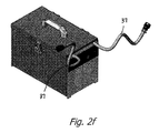
- FIG. 2 f is a perspective view of a battery charger in accordance with the present invention.
- FIG. 3 is a block diagram of each battery of FIGS. 2 a through 2 e.
- FIGS. 4 a and 4 b are battery control flow charts in accordance with the present invention.
- FIG. 5 is a charger block diagram for each of the two chargers in the charger of FIG. 2 f.
- FIGS. 6 , 7 and 8 are charger control flow charts in accordance with the present invention.
- FIG. 2 a is a perspective view of the chassis of the vehicle of FIGS. 1 a and 1 b , with FIG. 2 b being a side view of the chassis.
- FIG. 2 a shows a complete battery 20 and a battery container 22 , the vehicle of FIGS. 1 a and 1 b using two batteries for the operation thereof.
- the batteries 20 are aligned and slide into the vehicle on guides 24 , and when slid to their forward most position, make contact with connectors 26 fastened to the chassis.
- a typical battery 20 may be seen in FIGS. 2 c , 2 d and 2 e .
- FIG. 2 c is a view of a battery from the back
- FIG. 2 d a front view of the battery
- FIG. 2 e a side view of the battery.
- the power connector 28 within the battery does not project outward from the back of the battery as may be seen in FIG. 2 e , but rather is recessed for protection and to avoid inadvertent shorting of the battery terminals and the hazards presented thereby.
- a handle 30 At the front of the battery 20 is a handle 30 , a monitoring/recharging connector 32 , three lighting emitting diodes (LEDs) 34 and a push button switch 36 .
- Connector 32 in the present invention provides individual electrical connection to each cell in the battery, and further provides a serial communication link with a charger for control of the battery charging and monitoring the state of charge and health of the battery.
- push button switch 36 may be used for checking the state of charge of the battery through LEDs 34 on the battery, even when a charger is not connected to the battery.
- FIG. 2 f is a perspective view of a battery charger in accordance with the present invention.
- the battery charger has two cables 37 for plugging into connectors 32 on two batteries 20 to charge up to two batteries at a time.
- the word charger as used hereafter is used in two contexts, first for a charger for an individual battery, and second, for a pair of such chargers as packaged together as in FIG. 2 f.
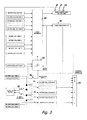
- FIG. 3 is a block diagram of the battery circuit.
- the particular batteries used are four cell batteries, though of course this is not a limitation of the invention.
- a microprocessor 38 in the battery monitors the battery cell voltage for all four cells, the first connection shown being for the battery ground, the second connection being for the first cell voltage, and then each cell voltage thereafter being measured relative to the prior cell voltage.
- the microprocessor also monitors battery cell temperature using a temperature sensor or similar device, and provides this information to a serial communication link 40 for communication to and from the battery through connector 32 when connected to a battery charger.
- the battery cell terminals themselves are also connected to connector 32 , in the embodiment shown through pins 3 , 4 , 5 , 6 and 7 , with the series connection of the batteries being connected to connector 28 in the battery for supplying power to the vehicle when charged and in the vehicle.
- the serial communication link 40 will control an active switch 42 which will cause the microprocessor to turn on and communicate with the charger when the charger is plugged in.
- the charger also contains three status display LEDs, duplicating the display provided by LEDs 34 on the battery. When the charger is not plugged in, the battery status may be determined by pressing switch 36 , which triggers microprocessor 38 on to power the status LEDs in accordance with the status as determined by the microprocessor.
- the microprocessor will shut off, of course turning off LEDs 34 and microprocessor 38 to save battery power.
- a resistor in the battery the resistance of which can be read by the charger over the serial communication link, the resistance being selected to indicate the battery chemistry for setting the recharging characteristics.
- FIG. 4 a is a flow chart for the battery control on the battery
- the microprocessor when the microprocessor is started, there is first an initialization process, and then it proceeds to read the cell voltages and the cell temperatures. It will then set the state of the LEDs (LED progress) in accordance with those readings. If a charger is plugged in, it will send that data through the serial communication link to the charger and similarly receive a data package from the charger. If a bad battery is detected (bad or excessively discharged), the status of LEDs 34 on the battery is updated (LED progress) to indicate the bad battery.
- FIG. 4 b is a flow chart illustrating the determination of the various battery states. For each type of battery used, a minimum voltage, an empty voltage, a half full or half charged voltage and a full or fully charged voltage for that type of battery is used.
- the empty voltage represents the low voltage of the battery's useful discharge cycle
- the half full voltage represents a voltage at or above which the battery is considered to have a state of charge of at least 50%
- the full voltage is the voltage the battery is presumed to bed fully charged.
- the minimum voltage is a voltage below the empty voltage, indicative not only of the discharge of the battery to below its useful voltage, but further indicative of a possible problem with the battery.
- all cells in the battery are tested to determine whether any are below the minimum (MIN) voltage, and if yes for any cell, the zero voltage battery flag is initiated. As shown at the top of the Figure, this is indicated on the battery LEDs by having the full and half full LEDs off and the empty LED flashing in one second intervals. If no cells are below the minimum, the cell voltages are then tested to determine if any of the cells are above the minimum voltage but less than the empty voltage. If they are, the low battery flag is initiated. This flag turns the full LED and half full LED off and the empty LED flashing, though now flashing in 100 millisecond intervals rather than one second intervals.
- the full LED will be off, the half full LED will blink in half second intervals and the empty LED will be on, indicating that the battery is more than empty though less than half full. If none of the cells fall between the empty and the half full voltage, the voltage readings are then tested to determine whether any cell is between the half full and full voltage. If so, the full diode will blink in half second periods, the half full diode will be on and the empty LED will be on. Finally if none of the cells fall between half full and full, then all cells must be fully charged, and accordingly all three LEDs are turned on.
- the sequence stops at that point to power the LEDs accordingly.
- the serial I/O connection will report the same to the charger.
- the LEDs will indicate the state of the battery as being between empty and half charged, though because the voltage of each cell will be communicated to the charger, the charger will have the information to determine which cell is the errant cell.
- FIG. 5 an overall block diagram of a battery charger in accordance with the present invention may be seen.
- the charger is controlled by a microprocessor control board 44 .
- the microprocessor control board 44 controls the charger under program control by controlling the connection of the charger to the cells through relays 46 , and controlling the charging mode of each cell based on information obtained from the battery over the serial communication link.
- CC MODE 1 is a low constant current mode, 7 amps in the preferred embodiment
- CC MODE 2 is a high constant current mode, 15 amps in the preferred embodiment
- CV MODE being a constant voltage charging mode representing the charging voltage limit for the 15 amp charging rate, the specific constant voltage used depending on the type (chemistry) of battery being charged.
- any of these three charging modes may be applied to the cells in a battery through relays 46 , though in the preferred embodiment, the same mode is applied to all cells of a battery, with the voltage of the lowest voltage cell determining the mode.
- the microprocessor may communicate with a battery connected to the connector 28 through the serial communication link 40 , and is configured to indicate not only that charging is in progress through LED 46 or finished through LED 48 , but also to indicate the state of charge of the battery through diodes 34 , replicating the indication on the battery itself.
- the charger can be activated by push button switch 52 , and once activated, will normally continue until all cells are fully charged, then disconnect the charger from the battery through relays 46 and continue to monitor the state of charge of the battery through the serial communication link.
- Push button switch 52 is also used to wake the battery up when the battery is very low capacity or completely drained.
- FIG. 6 part of the charger control flowchart for a charger in accordance with a preferred embodiment may be seen. Since the vehicle of FIG. 1 uses two batteries, the charger of the preferred embodiment is also capable of charging two batteries at the same time. It is, of course, also capable of charging only a single battery at a time, which may be connected to either port of the charger.
- the charger goes through an initialization process and then sends a request for data to the first battery connection. If there is no battery connected to that charger connection, or alternatively the battery that is connected is too dead to reply, the charger for that battery is disabled.
- the LEDs on that charger and battery are updated to indicate that the battery is being charged and the present state of charge of the battery, and the charger is then enabled with the logic flow then proceeding as identified as sequence 1 ( FIG. 7 ). Whether or not the charger for battery 1 was enabled, the charger then goes through the same process for battery 2 . Note that in either case, if no battery is connected to the charger, or alternatively the battery is too dead to respond, the charger for that battery will believe no battery is connected and accordingly will not begin the charging sequence. The charger will also check to see if either charger, Charger 1 for the first battery or Charger 2 for the second battery, has been turned on by control switches on the battery charger (charger # 1 enable pushbutton and charger # 2 enable pushbutton).
- sequence 1 and sequence 2 are identical sequences and accordingly only sequence 1 will be described herein in detail.
- Sequence 1 begins with a communication from the battery of the battery cell voltages and temperatures as well as battery type, which the charger then uses to update the LEDs on the charger to indicate that status. Even if the communication with the battery is unsuccessful, the charger proceeds with sequence 1 . The cells of the battery are tested to see if any cell is above the maximum temperature allowed, and if so, the charger is disabled and a bad battery is flagged. If not, the cells of the battery are then tested to see if any cell is below the minimum charge, and if yes, the charger is enabled and set to the CC mode 1 (7 amps) to charge the cells for 10 minutes, after which the cells are again tested to determine if any cell is below the minimum charge.
- the 10 minutes should be adequate to bring the voltage of any properly operating cell to above the minimum voltage. If it doesn't, the charger is disabled and the bad battery flag activated. If none of the cells are below the minimum voltage, or at least are no longer below the minimum voltage after the 10 minutes, the charger is set to CC mode 2 and the maximum timer set to a time more than adequate to charge a properly functioning battery. The LEDs are updated and the charger signals checked. If the check signal indicates 1) an alarm signal (overheating), 2) a working signal at zero volts (charger fault), 3) a cell temperature above the maximum allowable temperature, or 4) over voltage charging above the maximum allowable voltage (charger fault), the charger is disabled and a bad charger flag is activated.
- the charger is latched in the disable mode until the charger is recycled through the AC switch. Otherwise the LEDs will be continually updated, either until the battery is fully charged or the maximum timer times out.
- the CC mode 2 will charge the cells at 15 amps, but will reduce the charging rates as each cell reaches the CV mode. Once all cells are fully charged or the timer has timed out, the battery is allowed to sit without charging for 10 minutes to stabilize, within which time a faulty cell will show itself by an extraordinarily high self discharge rate.
- the LEDs indicating the state of the battery charge are updated, with the charger being disabled at the end of the 10 minutes and going into an auto enable mode.
- the cell temperatures are monitored, and if the temperature of any cell exceeds the maximum allowed, the charger is disabled and a bad battery flagged.
- the auto enable mode is shown in FIG. 8 .
- the charger will periodically test any cell to see if its voltage has fallen below 3 volts. If it has not, it will disable the charger and update the status of the LEDs on the charger to turn on the complete charge LED. If the voltage on a cell has fallen below 3 volts (depending on battery chemistry), the charger for that battery is then turned on and the charger returns to sequence 1 or 2 , identical sequences with sequence 1 being shown in FIG. 7 .
- charger # 1 has five LEDs (for each battery and charger) to indicate charger and battery status.
- LED 48 on indicates that the battery is being charged, and LED 50 on indicates the battery is fully charged.
- a bad battery is flagged by all of LEDs 34 flashing.
- a bad charger (over heat and over voltage) is flagged by LEDs 48 and 50 flashing.
- the LEDs 34 full half and empty) are used to indicate any of four battery states of charge for batteries not flagged as bad. These states of charge, duplicated by the LEDs on the battery itself, and sensed by cell voltages, are battery full (fully charged), between half full and full, between empty and half full, and between a minimum voltage and empty. Below the minimum voltage the battery is flagged as a bad battery.
- Empty means that the battery has reached its defined useful state of discharge and should be recharged. Between the minimum voltage and empty, the state of charge is flagged by the full and half LEDs 34 being off and the empty LED flashing. Between the empty and half full, the state of charge is flagged by the full LED 34 being off, the half LED flashing and the empty LED being on. Between the half full and full, the state of charge is flagged by the full LED 34 flashing and the half and empty LEDs being on. When full, all three LEDs 34 will be turned on. As shown in FIG. 5 , charger # 2 is the same configuration as charger # 1 . Charger # 1 and charger # 2 are independently controlled by the microprocessor.
- the battery is a four rechargeable cell battery, and thus the battery charger accommodates the charging of four cells per battery.
- the batteries and chargers in accordance with the present invention may also be configured for more or less cells, as desired.
Landscapes
- Engineering & Computer Science (AREA)
- Manufacturing & Machinery (AREA)
- Chemical & Material Sciences (AREA)
- Chemical Kinetics & Catalysis (AREA)
- Electrochemistry (AREA)
- General Chemical & Material Sciences (AREA)
- Power Engineering (AREA)
- Health & Medical Sciences (AREA)
- General Health & Medical Sciences (AREA)
- Medical Informatics (AREA)
- Charge And Discharge Circuits For Batteries Or The Like (AREA)
Abstract
Description
Claims (25)
Priority Applications (1)
| Application Number | Priority Date | Filing Date | Title |
|---|---|---|---|
| US12/053,226 US8072185B2 (en) | 2008-03-21 | 2008-03-21 | Batteries and chargers therefor |
Applications Claiming Priority (1)
| Application Number | Priority Date | Filing Date | Title |
|---|---|---|---|
| US12/053,226 US8072185B2 (en) | 2008-03-21 | 2008-03-21 | Batteries and chargers therefor |
Publications (2)
| Publication Number | Publication Date |
|---|---|
| US20090237032A1 US20090237032A1 (en) | 2009-09-24 |
| US8072185B2 true US8072185B2 (en) | 2011-12-06 |
Family
ID=41088202
Family Applications (1)
| Application Number | Title | Priority Date | Filing Date |
|---|---|---|---|
| US12/053,226 Expired - Fee Related US8072185B2 (en) | 2008-03-21 | 2008-03-21 | Batteries and chargers therefor |
Country Status (1)
| Country | Link |
|---|---|
| US (1) | US8072185B2 (en) |
Cited By (5)
| Publication number | Priority date | Publication date | Assignee | Title |
|---|---|---|---|---|
| USD735608S1 (en) * | 2012-10-22 | 2015-08-04 | T3 Motion, Inc. | Three wheeled vehicle |
| US20160084913A1 (en) * | 2013-05-29 | 2016-03-24 | Freescale Semiconductor, Inc. | Cell monitoring apparatus, battery monitoring apparatus, integrated circuit and method of monitoring a rechargeable cell |
| USD766131S1 (en) * | 2014-04-10 | 2016-09-13 | Segway, Inc. | Three-wheeled vehicle |
| US11381095B2 (en) * | 2018-02-01 | 2022-07-05 | Gs Yuasa International Ltd. | Management device, energy storage apparatus, and management method for energy storage device |
| US11515714B1 (en) | 2021-12-28 | 2022-11-29 | Beta Air, Llc | Methods and systems for mitigating charging failure for an electric aircraft |
Families Citing this family (13)
| Publication number | Priority date | Publication date | Assignee | Title |
|---|---|---|---|---|
| US9983645B2 (en) | 2010-06-29 | 2018-05-29 | International Business Machines Corporation | Managing electrical power in a virtual power delivery network |
| CN102313873B (en) * | 2010-07-08 | 2014-07-09 | 凹凸电子(武汉)有限公司 | Battery number detecting circuit and method and monitoring system |
| CN102655333B (en) * | 2011-03-04 | 2015-02-04 | 国基电子(上海)有限公司 | Battery charging device and charging method thereof |
| CN102259594A (en) * | 2011-05-18 | 2011-11-30 | 河海大学 | Advanced reduced instruction-set computer (RISC) machine (ARM)-based integrated information display system for automobile |
| JP2014052296A (en) * | 2011-09-09 | 2014-03-20 | Gs Yuasa Corp | Monitoring device |
| CN102522785A (en) * | 2011-11-22 | 2012-06-27 | 常熟市董浜镇华进电器厂 | Storage battery pack charging device |
| USD845177S1 (en) * | 2016-09-21 | 2019-04-09 | D.S. Raider Ltd. | Personal standing vehicle |
| USD829603S1 (en) * | 2016-12-26 | 2018-10-02 | Hangzhou Chic Intelligent Technology Co., Ltd. | Electric balance vehicle |
| JP1616504S (en) * | 2017-10-19 | 2018-10-29 | ||
| TWI686981B (en) * | 2018-08-22 | 2020-03-01 | 光陽工業股份有限公司 | Battery extraction device with light signal display function |
| IT201800020995A1 (en) * | 2018-12-24 | 2020-06-24 | Borgwarner System Lugo S R L | Battery charger with LED interface |
| USD979460S1 (en) * | 2021-03-10 | 2023-02-28 | Polestar Performance Ab | Electric trike vehicle |
| USD979461S1 (en) * | 2021-03-10 | 2023-02-28 | Polestar Performance Ab | Electric trike vehicle |
Citations (3)
| Publication number | Priority date | Publication date | Assignee | Title |
|---|---|---|---|---|
| US20040189248A1 (en) * | 2003-03-26 | 2004-09-30 | Boskovitch Paul E. | Battery pack for a battery-powered vehicle |
| US20070080662A1 (en) * | 2005-10-11 | 2007-04-12 | Deping Wu | Universal battery module and controller therefor |
| US20070273334A1 (en) * | 2002-11-22 | 2007-11-29 | Meyer Gary D | Method and system for charging multi-cell lithium-based batteries |
-
2008
- 2008-03-21 US US12/053,226 patent/US8072185B2/en not_active Expired - Fee Related
Patent Citations (3)
| Publication number | Priority date | Publication date | Assignee | Title |
|---|---|---|---|---|
| US20070273334A1 (en) * | 2002-11-22 | 2007-11-29 | Meyer Gary D | Method and system for charging multi-cell lithium-based batteries |
| US20040189248A1 (en) * | 2003-03-26 | 2004-09-30 | Boskovitch Paul E. | Battery pack for a battery-powered vehicle |
| US20070080662A1 (en) * | 2005-10-11 | 2007-04-12 | Deping Wu | Universal battery module and controller therefor |
Cited By (6)
| Publication number | Priority date | Publication date | Assignee | Title |
|---|---|---|---|---|
| USD735608S1 (en) * | 2012-10-22 | 2015-08-04 | T3 Motion, Inc. | Three wheeled vehicle |
| US20160084913A1 (en) * | 2013-05-29 | 2016-03-24 | Freescale Semiconductor, Inc. | Cell monitoring apparatus, battery monitoring apparatus, integrated circuit and method of monitoring a rechargeable cell |
| US9927492B2 (en) * | 2013-05-29 | 2018-03-27 | Nxp Usa, Inc. | Cell monitoring apparatus, battery monitoring apparatus, integrated circuit and method of monitoring a rechargeable cell |
| USD766131S1 (en) * | 2014-04-10 | 2016-09-13 | Segway, Inc. | Three-wheeled vehicle |
| US11381095B2 (en) * | 2018-02-01 | 2022-07-05 | Gs Yuasa International Ltd. | Management device, energy storage apparatus, and management method for energy storage device |
| US11515714B1 (en) | 2021-12-28 | 2022-11-29 | Beta Air, Llc | Methods and systems for mitigating charging failure for an electric aircraft |
Also Published As
| Publication number | Publication date |
|---|---|
| US20090237032A1 (en) | 2009-09-24 |
Similar Documents
| Publication | Publication Date | Title |
|---|---|---|
| US8072185B2 (en) | Batteries and chargers therefor | |
| US11447023B2 (en) | Portable vehicle battery jump start apparatus with safety protection and jumper cable device thereof | |
| US11787297B2 (en) | Battery charging device for charging a deeply discharged battery, and battery charging system and method | |
| AU2022201338B2 (en) | Portable vehicle battery jump start apparatus with safety protection | |
| US11108249B2 (en) | Communication to control charging of a rechargeable battery | |
| JP7304816B2 (en) | Portable or handheld vehicle battery jump-start device with battery cell equalization circuit | |
| EP3342623A2 (en) | Charging a lithium batery on a utility vehicle | |
| US5811959A (en) | Smart circuit board for multicell battery protection | |
| AU771405B2 (en) | Portable jump-starting battery pack with charge monitoring system | |
| US9112360B2 (en) | Power supply device | |
| EP2651006B1 (en) | Charging system comprising a charger and an adapter | |
| WO2016006152A1 (en) | Storage battery pack, and storage battery pack operation method | |
| JPS60241736A (en) | Battery charger | |
| EP3137916B1 (en) | Battery sleep mode management method | |
| US8538614B1 (en) | Rechargeable battery systems and methods | |
| US20050156567A1 (en) | Rechargeable electrical power supply unit for an electronic device of a bicycle | |
| CN107743674B (en) | Self-propelled electronic device | |
| US5594314A (en) | Secondary battery discharge adaptor | |
| JP7451693B2 (en) | Battery charging device, battery charging system and method for charging a deeply discharged battery | |
| AU719232B2 (en) | Electrical charging device with function to prevent erroneous electrical charging | |
| CN109698532B (en) | Charging control device, storage battery pack and charger | |
| US6747439B2 (en) | Conditioning of a rechargeable battery | |
| US20220407341A1 (en) | Battery charging device having a temperature sensor for providing temperature compensation during charging, and method of measuring depleted or discharged battery temperature for compensating charging of a battery charging device | |
| JP2014075256A (en) | Portable rechargeable power supply device | |
| JPH02202327A (en) | Battery charger for medical instrument |
Legal Events
| Date | Code | Title | Description |
|---|---|---|---|
| AS | Assignment |
Owner name: T3 MOTION, INC., CALIFORNIA Free format text: ASSIGNMENT OF ASSIGNORS INTEREST;ASSIGNORS:NAM, KI Y.;CAO, KENNETH TIEN;REEL/FRAME:020972/0539 Effective date: 20080429 |
|
| STCF | Information on status: patent grant |
Free format text: PATENTED CASE |
|
| AS | Assignment |
Owner name: JMJ FINANCIAL, CALIFORNIA Free format text: SECURITY AGREEMENT;ASSIGNORS:T3 MOTION, INC.;R3 MOTION, INC.;REEL/FRAME:028930/0579 Effective date: 20120810 |
|
| AS | Assignment |
Owner name: KEENER, JUSTION, D/B/A JMJ FINANCIAL, CALIFORNIA Free format text: CORRECTIVE ASSIGNMENT TO CORRECT THE RECEIVING PARTY NAME, PREVIOUSLY RECORDED ON REEL 028930 FRAME 0579. ASSIGNOR(S) HEREBY CONFIRMS THE SECURITY AGREEMENT;ASSIGNORS:T3 MOTION, INC.;R3 MOTION, INC.;REEL/FRAME:029058/0042 Effective date: 20120810 Owner name: KEENER, JUSTIN, D/B/A JMJ FINANCIAL, CALIFORNIA Free format text: CORRECTIVE ASSIGNMENT TO CORRECT THE RECEIVING PARTY NAME, PREVIOUSLY RECORDED ON REEL 028930 FRAME 0579. ASSIGNOR(S) HEREBY CONFIRMS THE SECURITY AGREEMENT;ASSIGNORS:T3 MOTION, INC.;R3 MOTION, INC.;REEL/FRAME:029058/0042 Effective date: 20120810 |
|
| AS | Assignment |
Owner name: MOMONA CAPITAL LLC, NEW YORK Free format text: SECURITY AGREEMENT;ASSIGNORS:T3 MOTION, INC.;R3 MOTION, INC.;T3 MOTION EUROPE LIMITED;REEL/FRAME:029608/0639 Effective date: 20121126 Owner name: BRIO CAPITAL MASTER FUND LTD., NEW YORK Free format text: SECURITY AGREEMENT;ASSIGNORS:T3 MOTION, INC.;R3 MOTION, INC.;T3 MOTION EUROPE LIMITED;REEL/FRAME:029608/0639 Effective date: 20121126 Owner name: THE SPECIAL EQUITIES GROUP, LLC, NEW YORK Free format text: SECURITY AGREEMENT;ASSIGNORS:T3 MOTION, INC.;R3 MOTION, INC.;T3 MOTION EUROPE LIMITED;REEL/FRAME:029608/0639 Effective date: 20121126 Owner name: JUSTIN KEENER D/B/A JMJ FINANCIAL, CALIFORNIA Free format text: SECURITY AGREEMENT;ASSIGNORS:T3 MOTION, INC.;R3 MOTION, INC.;T3 MOTION EUROPE LIMITED;REEL/FRAME:029608/0639 Effective date: 20121126 Owner name: T-ENERGY, INC., CALIFORNIA Free format text: SECURITY AGREEMENT;ASSIGNORS:T3 MOTION, INC.;R3 MOTION, INC.;T3 MOTION EUROPE LIMITED;REEL/FRAME:029608/0639 Effective date: 20121126 Owner name: HUDSON BAY MASTER FUND LTD, NEW YORK Free format text: SECURITY AGREEMENT;ASSIGNORS:T3 MOTION, INC.;R3 MOTION, INC.;T3 MOTION EUROPE LIMITED;REEL/FRAME:029608/0639 Effective date: 20121126 Owner name: ALPHA CAPITAL ANSTALT, LIECHTENSTEIN Free format text: SECURITY AGREEMENT;ASSIGNORS:T3 MOTION, INC.;R3 MOTION, INC.;T3 MOTION EUROPE LIMITED;REEL/FRAME:029608/0639 Effective date: 20121126 Owner name: TREBATCH, PERRY, NEW YORK Free format text: SECURITY AGREEMENT;ASSIGNORS:T3 MOTION, INC.;R3 MOTION, INC.;T3 MOTION EUROPE LIMITED;REEL/FRAME:029608/0639 Effective date: 20121126 Owner name: GOOD ENERGY SERVICES, LLC, OKLAHOMA Free format text: SECURITY AGREEMENT;ASSIGNORS:T3 MOTION, INC.;R3 MOTION, INC.;T3 MOTION EUROPE LIMITED;REEL/FRAME:029608/0639 Effective date: 20121126 Owner name: HONIG, BARRY, FLORIDA Free format text: SECURITY AGREEMENT;ASSIGNORS:T3 MOTION, INC.;R3 MOTION, INC.;T3 MOTION EUROPE LIMITED;REEL/FRAME:029608/0639 Effective date: 20121126 Owner name: CORDERO 2000 FAMILY TRUST, NEVADA Free format text: SECURITY AGREEMENT;ASSIGNORS:T3 MOTION, INC.;R3 MOTION, INC.;T3 MOTION EUROPE LIMITED;REEL/FRAME:029608/0639 Effective date: 20121126 Owner name: CHARDAN CAPITAL MARKETS, LLC, NEW YORK Free format text: SECURITY AGREEMENT;ASSIGNORS:T3 MOTION, INC.;R3 MOTION, INC.;T3 MOTION EUROPE LIMITED;REEL/FRAME:029608/0639 Effective date: 20121126 |
|
| FPAY | Fee payment |
Year of fee payment: 4 |
|
| AS | Assignment |
Owner name: R3 MOTION, INC., CALIFORNIA Free format text: RELEASE OF SECURITY INTEREST RECORDED AT REEL 028930 FRAME 0579, AND CORRECTED AT REEL 029058 FRAME 0042;ASSIGNOR:JMJ FINANCIAL;REEL/FRAME:036255/0826 Effective date: 20150803 Owner name: LENDER COLLECTIONS LLC, NEVADA Free format text: ASSIGNMENT OF ASSIGNORS INTEREST;ASSIGNOR:T3 MOTION, INC.;REEL/FRAME:036241/0001 Effective date: 20150803 |
|
| AS | Assignment |
Owner name: T3 MOTION, INC., CALIFORNIA Free format text: CORRECTION BY DECLARATION OF IMPROPERLY FILED ASSIGNMENTS RECORDED AT REEL 036241, FRAME 0001;ASSIGNOR:T3 MOTION, INC.;REEL/FRAME:040961/0463 Effective date: 20161213 |
|
| FEPP | Fee payment procedure |
Free format text: MAINTENANCE FEE REMINDER MAILED (ORIGINAL EVENT CODE: REM.); ENTITY STATUS OF PATENT OWNER: SMALL ENTITY |
|
| LAPS | Lapse for failure to pay maintenance fees |
Free format text: PATENT EXPIRED FOR FAILURE TO PAY MAINTENANCE FEES (ORIGINAL EVENT CODE: EXP.); ENTITY STATUS OF PATENT OWNER: SMALL ENTITY |
|
| STCH | Information on status: patent discontinuation |
Free format text: PATENT EXPIRED DUE TO NONPAYMENT OF MAINTENANCE FEES UNDER 37 CFR 1.362 |
|
| FP | Lapsed due to failure to pay maintenance fee |
Effective date: 20191206 |