US8065451B2 - Device for tapping USB power - Google Patents
Device for tapping USB power Download PDFInfo
- Publication number
- US8065451B2 US8065451B2 US11/776,974 US77697407A US8065451B2 US 8065451 B2 US8065451 B2 US 8065451B2 US 77697407 A US77697407 A US 77697407A US 8065451 B2 US8065451 B2 US 8065451B2
- Authority
- US
- United States
- Prior art keywords
- usb
- port
- power
- electronic device
- computer
- Prior art date
- Legal status (The legal status is an assumption and is not a legal conclusion. Google has not performed a legal analysis and makes no representation as to the accuracy of the status listed.)
- Active, expires
Links
Images


Classifications
-
- G—PHYSICS
- G06—COMPUTING; CALCULATING OR COUNTING
- G06F—ELECTRIC DIGITAL DATA PROCESSING
- G06F1/00—Details not covered by groups G06F3/00 - G06F13/00 and G06F21/00
- G06F1/26—Power supply means, e.g. regulation thereof
- G06F1/266—Arrangements to supply power to external peripherals either directly from the computer or under computer control, e.g. supply of power through the communication port, computer controlled power-strips
-
- G—PHYSICS
- G06—COMPUTING; CALCULATING OR COUNTING
- G06F—ELECTRIC DIGITAL DATA PROCESSING
- G06F1/00—Details not covered by groups G06F3/00 - G06F13/00 and G06F21/00
- G06F1/26—Power supply means, e.g. regulation thereof
- G06F1/32—Means for saving power
- G06F1/3203—Power management, i.e. event-based initiation of a power-saving mode
- G06F1/3234—Power saving characterised by the action undertaken
- G06F1/325—Power saving in peripheral device
- G06F1/3253—Power saving in bus
-
- Y—GENERAL TAGGING OF NEW TECHNOLOGICAL DEVELOPMENTS; GENERAL TAGGING OF CROSS-SECTIONAL TECHNOLOGIES SPANNING OVER SEVERAL SECTIONS OF THE IPC; TECHNICAL SUBJECTS COVERED BY FORMER USPC CROSS-REFERENCE ART COLLECTIONS [XRACs] AND DIGESTS
- Y02—TECHNOLOGIES OR APPLICATIONS FOR MITIGATION OR ADAPTATION AGAINST CLIMATE CHANGE
- Y02D—CLIMATE CHANGE MITIGATION TECHNOLOGIES IN INFORMATION AND COMMUNICATION TECHNOLOGIES [ICT], I.E. INFORMATION AND COMMUNICATION TECHNOLOGIES AIMING AT THE REDUCTION OF THEIR OWN ENERGY USE
- Y02D10/00—Energy efficient computing, e.g. low power processors, power management or thermal management
Definitions
- USB Universal Serial Bus
- the USB host port may provide insufficient power for the electronic device to operate.
- Typical USB host ports supply current up to 100 mA in compliance with USB standard 7.2.1.3. if a proper initialization process is not performed.
- the USB host port implements over current protection and the electronic device requires more than 100 mA of current (i.e. high power) to operate, it is possible that the USB voltage (V BUS ) will be turned off in response to connecting the electronic device to the USB host port.
- V BUS USB voltage
- the USB host port may still be disabled and in an unusable state until the user manually resets the USB host port.
- the electronic device will loose power when the USB host port enters a suspend mode.
- the USB host port will suspend the USB bus if there are no data transactions over the USB bus for a certain time. After the USB host port suspends the USB bus for lack of data transactions, the USB power draw is limited to 500 ⁇ A and the electronic device may loose power or be reset.
- tapping USB power without proper initialization may also damage the USB host port.
- the computer may implement an unrecoverable protection mechanism on the USB host port. Connecting an electronic device to the USB host port may generate inrush current. Depending on the protected current limitation of the USB host port, this inrush current may exceed the current limitation of the USB host port and result in an unrecoverable state where the USB host port is inoperable.
- the device includes a universal serial bus (USB) port comprising a data terminal and a power terminal to receive power from a remote USB port.
- the device includes a controller coupled to the data terminal of the USB port to provide a USB initialization signal.
- USB universal serial bus
- FIG. 1 is a block diagram illustrating one embodiment of a system.
- FIG. 2 is a diagram illustrating one embodiment of USB cable connections to a USB slave port.
- FIG. 3 is a diagram illustrating one embodiment of an electronic device tapping USB power from a computer.
- FIG. 4 is a flow diagram illustrating one embodiment of a method for an electronic device to tap USB power from a USB host port.
- FIG. 1 is a block diagram illustrating one embodiment of a system 100 .
- System 100 includes a computer 102 and an electronic device 120 .
- Computer 102 includes a data port 104 , a Universal Serial Bus (USB) host port 106 , and other components (not shown), such as a processor and memory.
- Electronic device 120 includes a data interface 122 , a USB slave port 124 , and a controller 130 .
- Data interface 122 is electrically coupled to controller 130 through signal path 126 .
- USB slave port 124 is electrically coupled to controller 130 through signal path 128 .
- Data port 104 of computer 102 is electrically coupled to data interface 122 of electronic device 120 through a data cable 110 .
- USB host port 106 of computer 102 is electrically coupled to USB slave port 124 of electronic device 120 through a USB cable 112 .
- Electronic device 120 is configured to tap USB power from USB host port 106 while fully complying with the USB standard. Electronic device 120 taps the USB power from USB host port 106 without installing any specific driver or supporting software for supporting or driving electronic device 120 on computer 102 . In addition, electronic device 120 reliably receives up to 500 mA of constant current from USB host port 106 . Electronic device 120 receives sufficient power from USB host port 106 , and USB host port 106 is not suspended, disabled, or damaged. In addition electronic device 120 provides energy savings by powering down or shutting down with computer 102 .
- Computer 102 includes any suitable logical computing device including a USB host port 106 .
- computer 102 is a personal computer (PC), workstation, laptop, handheld computer, or other suitable computing device.
- Data port 104 transmits and/or receives data using any suitable data transmission method.
- Data port 104 includes an Ethernet port, an IEEE 1394 port, a parallel data port, a serial data port, a game port, or any other suitable data port.
- USB host port 106 is a standard USB host port for transmitting and receiving serial data and for providing USB power. In a first state before initialization, USB host port 106 provides up to 100 mA of current to electronic device 120 through USB cable 112 . In a second state after initialization, USB host port 106 provides up to 500 mA of current (i.e. high power) to electronic device 120 through USB cable 112 .
- Electronic device 120 may include any suitable device that uses a predetermined current to operate. For example, in one embodiment, electronic device 120 uses a current higher than the predefined current available by the USB standard. In one embodiment, the current may be up to 500 mA or higher than 500 mA. In one embodiment, electronic device 120 is an Ethernet Asymmetric Digital Subscriber Line (ADSL) modem, an Ethernet Internet Protocol (IP) phone, an Ethernet Analog Telephone Adapter (ATA), or any other suitable electronic device other than a network adaptor. In one embodiment, electronic device 120 transmits and/or receives data from computer 102 through data interface 122 . In another embodiment, data interface 122 is excluded and electronic device 120 does not transmit and/or receive data from computer 102 .
- ADSL Ethernet Asymmetric Digital Subscriber Line
- IP Internet Protocol
- ATA Ethernet Analog Telephone Adapter
- Data interface 122 transmits and/or receives data from computer 102 through data cable 110 .
- data interface 122 include an Ethernet port, an IEEE 1394 port, a parallel data port, a serial data port, a game port, or any other suitable data port complementary to data port 104 of computer 102 .
- USB slave port 124 receives USB power and transmits and/or receives control signals from USB host port 106 of computer 102 through USB cable 112 .
- Controller 130 includes a microprocessor, microcontroller, or other suitable logic circuitry for controlling the operation of electronic device 120 .
- Controller 130 controls data interface 122 through signal path 126 to transmit and/or receive data from computer 102 .
- Controller 130 controls USB slave port 124 through signal path 128 to receive and maintain USB power from computer 102 to power electronic device 120 .
- Electronic device 120 mimics a Remote Network Driver Interface Specification (RNDIS) device to tap USB power from USB host port 106 of computer 102 .
- Electronic device 120 initializes electronic device 120 as a RNDIS device and utilizes the RNDIS control protocols to keep electronic device 120 active. Since RNDIS is built into Windows, software installation on computer 102 and the associated maintenance of that software is eliminated. Electronic device 120 is properly installed in compliance with the USB standard. Electronic device 120 uses the full USB power management mechanism, receives power reliably, and conforms to CE certification.
- RNDIS Remote Network Driver Interface Specification
- FIG. 2 is a diagram illustrating one embodiment of USB cable 112 connections to USB slave port 124 of electronic device 120 .
- USB slave port 124 includes a connector 140 including inputs and/or outputs 142 a - 142 d .
- USB cable 112 includes a USB power (V BUS ) line 112 a , complementary data lines (D+ and D ⁇ ) 112 b and 112 c , and a ground (GND) line 112 d .
- V BUS line 112 a is electrically coupled to input 142 a .
- Complementary data lines D+ 112 b and D ⁇ 112 c are electrically coupled to inputs/outputs 142 b and 142 c , respectively.
- Ground line 112 d is electrically coupled to input 142 d.
- USB slave port 124 uses all four USB lines 112 a - 112 d and associated inputs and/or outputs 142 a - 142 d to comply with the USB standard for receiving and maintaining USB power for operating electronic device 120 .
- FIG. 3 is a diagram illustrating one embodiment of a system 150 .
- System 150 includes a laptop computer 152 and an electronic device 158 .
- Computer 152 is electrically coupled to electronic device 158 through an Ethernet cable 154 and through a USB cable 156 .
- electronic device 158 includes an ADSL modem, an IP phone, an ATA, or other suitable electronic device.
- Electronic device 158 transmits and/or receives data from computer 152 through Ethernet cable 154 .
- Electronic device 158 receives and maintains USB power from computer 152 through USB cable 156 .
- USB connection between computer 152 and electronic device 158 is compliant with the USB standard.
- Computer 152 recognizes both the Ethernet connection and the USB connection of electronic device 158 .
- computer 152 Upon connecting USB cable 156 between electronic device 158 and computer 152 , computer 152 initiates the device enumeration and initialization procedure in compliance with the USB standard.
- electronic device 158 informs computer 152 through USB cable 156 that electronic device 158 is an RNDIS device requiring high power (i.e., up to 500 mA).
- electronic device 158 After the completion of the initialization procedure, electronic device 158 enters into an RNDIS data initialized state. Data traffic between computer 152 and electronic device 158 passes through Ethernet cable 154 . No data traffic between computer 152 and electronic device 158 passes through USB cable 156 . With no data traffic passing through USB cable 156 , computer 152 will suspend the USB device (i.e., electronic device 158 in this embodiment). In a suspended state, electronic device 158 is allowed to draw very little (e.g., 500 ⁇ A) current. To prevent computer 152 from suspending electronic device 158 , electronic device 158 transmits remote NDIS keep alive signals to computer 152 through USB cable 156 as described below with reference to FIG. 4 . In this way, electronic device 158 receives and maintains up to 500 mA of current from computer 152 while complying with the USB standard and without installing additional software on computer 152 .
- USB cable 156 With no data traffic passing through USB cable 156 , computer 152 will suspend the USB device (i.e., electronic device
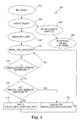
- FIG. 4 is a flow diagram illustrating one embodiment of a method 200 for an electronic device to tap USB power from a USB host port.
- the electronic device such as electronic device 120 previously described and illustrated with reference to FIG. 2 or electronic device 158 previously described and illustrated with reference to FIG. 3 is disconnected and therefore not powered.
- a USB cable is connected between the electronic device and the USB host port of a computer, such as computer 102 previously described and illustrated with reference to FIG. 1 or computer 152 previously described and illustrated with reference to FIG. 3 .
- the USB host port of the computer then initializes the USB connection to the electronic device.
- the electronic device is granted 500 mA of current to power the electronic device.
- the electronic device is powered and fully functional.
- the electronic device is initialized as an RNDIS device.
- the electronic device enters an RNDIS data initialized state.
- the electronic device determines whether an RNDIS keep alive timeout period (i.e., 5 seconds) minus one second (i.e., 4 seconds) has been reached. If the keep alive timeout period minus one second has not been reached, then the electronic device remains in the RNDIS data initialized state at 212 .
- the electronic device determines whether the electronic device has received a remote NDIS keep alive message from the computer. If the electronic device has not received a remote NDIS keep alive message from the computer, then at 220 the electronic device generates the remote NDIS keep alive message and passes it to the computer through the USB cable and the electronic device returns to the RNDIS data initialized state at 212 . If the electronic device has received the remote NDIS keep alive message from the computer, then at 218 the electronic device replies to the computer with a remote NDIS keep alive completion signal and the electronic device returns to the RNDIS data initialized state at 212 . The keep alive process for the electronic device is repeated such that the electronic device maintains up to 500 mA of current through the USB cable from the USB host port of the computer.
- Embodiments of the present invention provide an electronic device for tapping USB power from a USB host port of a computer while complying with the USB standard.
- the electronic device receives and maintains the USB power from the USB host port of the computer without installing software on the computer.
Abstract
Description
Claims (12)
Priority Applications (2)
| Application Number | Priority Date | Filing Date | Title |
|---|---|---|---|
| US11/776,974 US8065451B2 (en) | 2007-07-12 | 2007-07-12 | Device for tapping USB power |
| US13/237,991 US8275919B2 (en) | 2007-07-12 | 2011-09-21 | Device for tapping USB power |
Applications Claiming Priority (1)
| Application Number | Priority Date | Filing Date | Title |
|---|---|---|---|
| US11/776,974 US8065451B2 (en) | 2007-07-12 | 2007-07-12 | Device for tapping USB power |
Related Child Applications (1)
| Application Number | Title | Priority Date | Filing Date |
|---|---|---|---|
| US13/237,991 Continuation US8275919B2 (en) | 2007-07-12 | 2011-09-21 | Device for tapping USB power |
Publications (2)
| Publication Number | Publication Date |
|---|---|
| US20090019186A1 US20090019186A1 (en) | 2009-01-15 |
| US8065451B2 true US8065451B2 (en) | 2011-11-22 |
Family
ID=40254058
Family Applications (2)
| Application Number | Title | Priority Date | Filing Date |
|---|---|---|---|
| US11/776,974 Active 2029-10-11 US8065451B2 (en) | 2007-07-12 | 2007-07-12 | Device for tapping USB power |
| US13/237,991 Active US8275919B2 (en) | 2007-07-12 | 2011-09-21 | Device for tapping USB power |
Family Applications After (1)
| Application Number | Title | Priority Date | Filing Date |
|---|---|---|---|
| US13/237,991 Active US8275919B2 (en) | 2007-07-12 | 2011-09-21 | Device for tapping USB power |
Country Status (1)
| Country | Link |
|---|---|
| US (2) | US8065451B2 (en) |
Cited By (3)
| Publication number | Priority date | Publication date | Assignee | Title |
|---|---|---|---|---|
| US20080153959A1 (en) * | 2006-12-20 | 2008-06-26 | General Electric Company | Thermally Conducting and Electrically Insulating Moldable Compositions and Methods of Manufacture Thereof |
| US8552101B2 (en) | 2011-02-25 | 2013-10-08 | Sabic Innovative Plastics Ip B.V. | Thermally conductive and electrically insulative polymer compositions containing a low thermally conductive filler and uses thereof |
| US8741998B2 (en) | 2011-02-25 | 2014-06-03 | Sabic Innovative Plastics Ip B.V. | Thermally conductive and electrically insulative polymer compositions containing a thermally insulative filler and uses thereof |
Families Citing this family (2)
| Publication number | Priority date | Publication date | Assignee | Title |
|---|---|---|---|---|
| KR101075792B1 (en) | 2011-01-20 | 2011-10-21 | 주식회사 솔라시아 | Usb hardware security module, system for security certifincluding usb hardware security module and method thereof |
| WO2017086920A1 (en) * | 2015-11-16 | 2017-05-26 | Hewlett-Packard Development Company, L.P. | Data communication cables with power |
Citations (11)
| Publication number | Priority date | Publication date | Assignee | Title |
|---|---|---|---|---|
| US6563866B1 (en) | 1999-08-09 | 2003-05-13 | Gutzmer Enterprises | Bus-powered modem interface device |
| EP1367685A1 (en) | 2002-05-31 | 2003-12-03 | Whirlpool Corporation | Electronic system for power consumption management of appliances |
| US20040148539A1 (en) * | 2003-01-28 | 2004-07-29 | Leydier Robert Antoine | Method and apparatus for clock synthesis using universal serial bus downstream received signals |
| US20050138214A1 (en) * | 2001-08-31 | 2005-06-23 | Microsoft Corporation | Point-to-point data communication implemented with multipoint network data communication |
| US20050248966A1 (en) * | 2004-05-10 | 2005-11-10 | Naoya Matsui | Portable terminal and USB device |
| US20060029062A1 (en) * | 2004-07-23 | 2006-02-09 | Citrix Systems, Inc. | Methods and systems for securing access to private networks using encryption and authentication technology built in to peripheral devices |
| US7069347B1 (en) | 2002-09-27 | 2006-06-27 | Cypress Semiconductor Corporation | Device and method for adapting speed of a USB device based on available power |
| US7072989B1 (en) * | 2002-09-27 | 2006-07-04 | Cypress Semiconductor, Inc. | USB peripheral device storing an indication of an operating power mode when a host went into hibernate and restarting at the power mode accordingly |
| EP1710662A1 (en) | 2005-04-07 | 2006-10-11 | Research In Motion Limited | Device and Method for Powering a Peripheral Device |
| US20080104422A1 (en) * | 2006-10-30 | 2008-05-01 | Sony Ericsson Mobile Communications Ab | Method of Maintaining a USB Active State Without Data Transfer |
| US20080130532A1 (en) * | 2006-11-30 | 2008-06-05 | Nokia Corporation | Packet radio communication device |
Family Cites Families (4)
| Publication number | Priority date | Publication date | Assignee | Title |
|---|---|---|---|---|
| US6360269B1 (en) * | 1998-11-02 | 2002-03-19 | Nortel Networks Limited | Protected keepalive message through the internet |
| US7287099B1 (en) * | 2003-03-18 | 2007-10-23 | Unisys Corporation | System for support of remote console by emulation of local console with multipath data flow structure |
| US7412576B2 (en) * | 2004-12-08 | 2008-08-12 | Hitachi, Ltd. | Remote copy system having multiple data centers |
| GB0526029D0 (en) * | 2005-12-21 | 2006-02-01 | Nokia Corp | Managing connections in a wireless communications network |
-
2007
- 2007-07-12 US US11/776,974 patent/US8065451B2/en active Active
-
2011
- 2011-09-21 US US13/237,991 patent/US8275919B2/en active Active
Patent Citations (11)
| Publication number | Priority date | Publication date | Assignee | Title |
|---|---|---|---|---|
| US6563866B1 (en) | 1999-08-09 | 2003-05-13 | Gutzmer Enterprises | Bus-powered modem interface device |
| US20050138214A1 (en) * | 2001-08-31 | 2005-06-23 | Microsoft Corporation | Point-to-point data communication implemented with multipoint network data communication |
| EP1367685A1 (en) | 2002-05-31 | 2003-12-03 | Whirlpool Corporation | Electronic system for power consumption management of appliances |
| US7069347B1 (en) | 2002-09-27 | 2006-06-27 | Cypress Semiconductor Corporation | Device and method for adapting speed of a USB device based on available power |
| US7072989B1 (en) * | 2002-09-27 | 2006-07-04 | Cypress Semiconductor, Inc. | USB peripheral device storing an indication of an operating power mode when a host went into hibernate and restarting at the power mode accordingly |
| US20040148539A1 (en) * | 2003-01-28 | 2004-07-29 | Leydier Robert Antoine | Method and apparatus for clock synthesis using universal serial bus downstream received signals |
| US20050248966A1 (en) * | 2004-05-10 | 2005-11-10 | Naoya Matsui | Portable terminal and USB device |
| US20060029062A1 (en) * | 2004-07-23 | 2006-02-09 | Citrix Systems, Inc. | Methods and systems for securing access to private networks using encryption and authentication technology built in to peripheral devices |
| EP1710662A1 (en) | 2005-04-07 | 2006-10-11 | Research In Motion Limited | Device and Method for Powering a Peripheral Device |
| US20080104422A1 (en) * | 2006-10-30 | 2008-05-01 | Sony Ericsson Mobile Communications Ab | Method of Maintaining a USB Active State Without Data Transfer |
| US20080130532A1 (en) * | 2006-11-30 | 2008-06-05 | Nokia Corporation | Packet radio communication device |
Non-Patent Citations (1)
| Title |
|---|
| Microsoft, "Remote NDIS Specification" Revision 1.1, Aug. 9, 2002. * |
Cited By (3)
| Publication number | Priority date | Publication date | Assignee | Title |
|---|---|---|---|---|
| US20080153959A1 (en) * | 2006-12-20 | 2008-06-26 | General Electric Company | Thermally Conducting and Electrically Insulating Moldable Compositions and Methods of Manufacture Thereof |
| US8552101B2 (en) | 2011-02-25 | 2013-10-08 | Sabic Innovative Plastics Ip B.V. | Thermally conductive and electrically insulative polymer compositions containing a low thermally conductive filler and uses thereof |
| US8741998B2 (en) | 2011-02-25 | 2014-06-03 | Sabic Innovative Plastics Ip B.V. | Thermally conductive and electrically insulative polymer compositions containing a thermally insulative filler and uses thereof |
Also Published As
| Publication number | Publication date |
|---|---|
| US20090019186A1 (en) | 2009-01-15 |
| US20120011379A1 (en) | 2012-01-12 |
| US8275919B2 (en) | 2012-09-25 |
Similar Documents
| Publication | Publication Date | Title |
|---|---|---|
| US8880909B2 (en) | Auto-detect polling for correct handshake to USB client | |
| US7523338B2 (en) | Apparatus and method to support USB enumeration of a bus powered handheld device | |
| EP1550045B1 (en) | Device operable as both a host and a non-host (i.e. dual-mode device) | |
| US9494989B2 (en) | Power distribution inside cable | |
| US20040063464A1 (en) | High-speed data and power source interface cable for mobile devices | |
| US7293118B1 (en) | Apparatus and method for dynamically providing hub or host operations | |
| US8275919B2 (en) | Device for tapping USB power | |
| US20120290761A1 (en) | USB Converter and Related Method | |
| US9940277B2 (en) | Multi-channel peripheral interconnect supporting simultaneous video and bus protocols | |
| EP1775652B1 (en) | Apparatus and method to support USB enumeration of a BUS powered handheld device | |
| EP1139226A1 (en) | Method of emulating an attachment and detachment of a USB device | |
| CN113741670A (en) | USB interface circuit and method for low power operation | |
| EP1685496B1 (en) | An interface for serial data communication | |
| WO2006107509A2 (en) | Dual usb port device | |
| US8266348B2 (en) | System and method of communicating with portable devices | |
| CN102694722B (en) | Bridger and its method of operation | |
| KR100711006B1 (en) | Apparatus for Controlling VBUS Power in USB Device | |
| JP2002190848A (en) | Interface adapting device | |
| CN116945782A (en) | Printer and control method thereof | |
| TW202328934A (en) | Usb chip and operation method thereof | |
| CN115552384A (en) | USB/Lei Li interface to Ethernet adapter with dynamic multiplexing power supply | |
| KR20040103988A (en) | Lan adapter and control method thereof |
Legal Events
| Date | Code | Title | Description |
|---|---|---|---|
| AS | Assignment |
Owner name: INFINEON TECHNOLOGIES AG, GERMANY Free format text: ASSIGNMENT OF ASSIGNORS INTEREST;ASSIGNORS:JIAXIANG, SHI;VOLKENING, INGO;REEL/FRAME:019553/0831 Effective date: 20070628 |
|
| AS | Assignment |
Owner name: INFINEON TECHNOLOGIES WIRELESS SOLUTIONS GMBH,GERM Free format text: ASSIGNMENT OF ASSIGNORS INTEREST;ASSIGNOR:INFINEON TECHNOLOGIES AG;REEL/FRAME:024483/0001 Effective date: 20090703 Owner name: INFINEON TECHNOLOGIES WIRELESS SOLUTIONS GMBH, GER Free format text: ASSIGNMENT OF ASSIGNORS INTEREST;ASSIGNOR:INFINEON TECHNOLOGIES AG;REEL/FRAME:024483/0001 Effective date: 20090703 |
|
| AS | Assignment |
Owner name: LANTIQ DEUTSCHLAND GMBH,GERMANY Free format text: ASSIGNMENT OF ASSIGNORS INTEREST;ASSIGNOR:INFINEON TECHNOLOGIES WIRELESS SOLUTIONS GMBH;REEL/FRAME:024529/0656 Effective date: 20091106 Owner name: LANTIQ DEUTSCHLAND GMBH, GERMANY Free format text: ASSIGNMENT OF ASSIGNORS INTEREST;ASSIGNOR:INFINEON TECHNOLOGIES WIRELESS SOLUTIONS GMBH;REEL/FRAME:024529/0656 Effective date: 20091106 |
|
| FEPP | Fee payment procedure |
Free format text: PAYER NUMBER DE-ASSIGNED (ORIGINAL EVENT CODE: RMPN); ENTITY STATUS OF PATENT OWNER: LARGE ENTITY Free format text: PAYOR NUMBER ASSIGNED (ORIGINAL EVENT CODE: ASPN); ENTITY STATUS OF PATENT OWNER: LARGE ENTITY |
|
| AS | Assignment |
Owner name: DEUTSCHE BANK AG NEW YORK BRANCH, AS COLLATERAL AG Free format text: GRANT OF SECURITY INTEREST IN U.S. PATENTS;ASSIGNOR:LANTIQ DEUTSCHLAND GMBH;REEL/FRAME:025406/0677 Effective date: 20101116 |
|
| STCF | Information on status: patent grant |
Free format text: PATENTED CASE |
|
| AS | Assignment |
Owner name: LANTIQ BETEILIGUNGS-GMBH & CO. KG, GERMANY Free format text: RELEASE OF SECURITY INTEREST RECORDED AT REEL/FRAME 025413/0340 AND 025406/0677;ASSIGNOR:DEUTSCHE BANK AG NEW YORK BRANCH, AS COLLATERAL AGENT;REEL/FRAME:035453/0712 Effective date: 20150415 |
|
| FPAY | Fee payment |
Year of fee payment: 4 |
|
| AS | Assignment |
Owner name: LANTIQ BETEILIGUNGS-GMBH & CO. KG, GERMANY Free format text: MERGER;ASSIGNOR:LANTIQ DEUTSCHLAND GMBH;REEL/FRAME:044907/0045 Effective date: 20150303 |
|
| AS | Assignment |
Owner name: LANTIQ BETEILIGUNGS-GMBH & CO. KG, GERMANY Free format text: MERGER AND CHANGE OF NAME;ASSIGNORS:LANTIQ DEUTSCHLAND GMBH;LANTIQ BETEILIGUNGS-GMBH & CO. KG;REEL/FRAME:045085/0292 Effective date: 20150303 |
|
| MAFP | Maintenance fee payment |
Free format text: PAYMENT OF MAINTENANCE FEE, 8TH YEAR, LARGE ENTITY (ORIGINAL EVENT CODE: M1552); ENTITY STATUS OF PATENT OWNER: LARGE ENTITY Year of fee payment: 8 |
|
| AS | Assignment |
Owner name: INTEL CORPORATION, CALIFORNIA Free format text: ASSIGNMENT OF ASSIGNORS INTEREST;ASSIGNOR:LANTIQ BETEILIGUNGS-GMBH & CO. KG;REEL/FRAME:053259/0678 Effective date: 20200710 |
|
| AS | Assignment |
Owner name: MAXLINEAR, INC., CALIFORNIA Free format text: ASSIGNMENT OF ASSIGNORS INTEREST;ASSIGNOR:INTEL CORPORATION;REEL/FRAME:053626/0636 Effective date: 20200731 |
|
| AS | Assignment |
Owner name: WELLS FARGO BANK, NATIONAL ASSOCIATION, COLORADO Free format text: SECURITY AGREEMENT;ASSIGNORS:MAXLINEAR, INC.;MAXLINEAR COMMUNICATIONS, LLC;EXAR CORPORATION;REEL/FRAME:056816/0089 Effective date: 20210708 |
|
| MAFP | Maintenance fee payment |
Free format text: PAYMENT OF MAINTENANCE FEE, 12TH YEAR, LARGE ENTITY (ORIGINAL EVENT CODE: M1553); ENTITY STATUS OF PATENT OWNER: LARGE ENTITY Year of fee payment: 12 |