US8046053B2 - System and method for modifying images of a body part - Google Patents
System and method for modifying images of a body part Download PDFInfo
- Publication number
- US8046053B2 US8046053B2 US11/311,740 US31174005A US8046053B2 US 8046053 B2 US8046053 B2 US 8046053B2 US 31174005 A US31174005 A US 31174005A US 8046053 B2 US8046053 B2 US 8046053B2
- Authority
- US
- United States
- Prior art keywords
- procedure
- image data
- data set
- during
- body portions
- Prior art date
- Legal status (The legal status is an assumption and is not a legal conclusion. Google has not performed a legal analysis and makes no representation as to the accuracy of the status listed.)
- Expired - Fee Related, expires
Links
Images


Classifications
-
- A—HUMAN NECESSITIES
- A61—MEDICAL OR VETERINARY SCIENCE; HYGIENE
- A61B—DIAGNOSIS; SURGERY; IDENTIFICATION
- A61B5/00—Measuring for diagnostic purposes; Identification of persons
- A61B5/0059—Measuring for diagnostic purposes; Identification of persons using light, e.g. diagnosis by transillumination, diascopy, fluorescence
- A61B5/0073—Measuring for diagnostic purposes; Identification of persons using light, e.g. diagnosis by transillumination, diascopy, fluorescence by tomography, i.e. reconstruction of 3D images from 2D projections
-
- A—HUMAN NECESSITIES
- A61—MEDICAL OR VETERINARY SCIENCE; HYGIENE
- A61B—DIAGNOSIS; SURGERY; IDENTIFICATION
- A61B34/00—Computer-aided surgery; Manipulators or robots specially adapted for use in surgery
- A61B34/20—Surgical navigation systems; Devices for tracking or guiding surgical instruments, e.g. for frameless stereotaxis
-
- A—HUMAN NECESSITIES
- A61—MEDICAL OR VETERINARY SCIENCE; HYGIENE
- A61B—DIAGNOSIS; SURGERY; IDENTIFICATION
- A61B5/00—Measuring for diagnostic purposes; Identification of persons
- A61B5/0059—Measuring for diagnostic purposes; Identification of persons using light, e.g. diagnosis by transillumination, diascopy, fluorescence
- A61B5/0062—Arrangements for scanning
- A61B5/0064—Body surface scanning
-
- A—HUMAN NECESSITIES
- A61—MEDICAL OR VETERINARY SCIENCE; HYGIENE
- A61B—DIAGNOSIS; SURGERY; IDENTIFICATION
- A61B5/00—Measuring for diagnostic purposes; Identification of persons
- A61B5/06—Devices, other than using radiation, for detecting or locating foreign bodies ; determining position of probes within or on the body of the patient
- A61B5/061—Determining position of a probe within the body employing means separate from the probe, e.g. sensing internal probe position employing impedance electrodes on the surface of the body
-
- A—HUMAN NECESSITIES
- A61—MEDICAL OR VETERINARY SCIENCE; HYGIENE
- A61B—DIAGNOSIS; SURGERY; IDENTIFICATION
- A61B5/00—Measuring for diagnostic purposes; Identification of persons
- A61B5/103—Detecting, measuring or recording devices for testing the shape, pattern, colour, size or movement of the body or parts thereof, for diagnostic purposes
- A61B5/107—Measuring physical dimensions, e.g. size of the entire body or parts thereof
- A61B5/1077—Measuring of profiles
-
- A—HUMAN NECESSITIES
- A61—MEDICAL OR VETERINARY SCIENCE; HYGIENE
- A61B—DIAGNOSIS; SURGERY; IDENTIFICATION
- A61B6/00—Apparatus for radiation diagnosis, e.g. combined with radiation therapy equipment
- A61B6/12—Devices for detecting or locating foreign bodies
-
- A—HUMAN NECESSITIES
- A61—MEDICAL OR VETERINARY SCIENCE; HYGIENE
- A61B—DIAGNOSIS; SURGERY; IDENTIFICATION
- A61B6/00—Apparatus for radiation diagnosis, e.g. combined with radiation therapy equipment
- A61B6/50—Clinical applications
- A61B6/501—Clinical applications involving diagnosis of head, e.g. neuroimaging, craniography
-
- A—HUMAN NECESSITIES
- A61—MEDICAL OR VETERINARY SCIENCE; HYGIENE
- A61B—DIAGNOSIS; SURGERY; IDENTIFICATION
- A61B8/00—Diagnosis using ultrasonic, sonic or infrasonic waves
-
- A—HUMAN NECESSITIES
- A61—MEDICAL OR VETERINARY SCIENCE; HYGIENE
- A61B—DIAGNOSIS; SURGERY; IDENTIFICATION
- A61B8/00—Diagnosis using ultrasonic, sonic or infrasonic waves
- A61B8/52—Devices using data or image processing specially adapted for diagnosis using ultrasonic, sonic or infrasonic waves
- A61B8/5215—Devices using data or image processing specially adapted for diagnosis using ultrasonic, sonic or infrasonic waves involving processing of medical diagnostic data
- A61B8/5238—Devices using data or image processing specially adapted for diagnosis using ultrasonic, sonic or infrasonic waves involving processing of medical diagnostic data for combining image data of patient, e.g. merging several images from different acquisition modes into one image
-
- A—HUMAN NECESSITIES
- A61—MEDICAL OR VETERINARY SCIENCE; HYGIENE
- A61B—DIAGNOSIS; SURGERY; IDENTIFICATION
- A61B90/00—Instruments, implements or accessories specially adapted for surgery or diagnosis and not covered by any of the groups A61B1/00 - A61B50/00, e.g. for luxation treatment or for protecting wound edges
- A61B90/10—Instruments, implements or accessories specially adapted for surgery or diagnosis and not covered by any of the groups A61B1/00 - A61B50/00, e.g. for luxation treatment or for protecting wound edges for stereotaxic surgery, e.g. frame-based stereotaxis
-
- A—HUMAN NECESSITIES
- A61—MEDICAL OR VETERINARY SCIENCE; HYGIENE
- A61B—DIAGNOSIS; SURGERY; IDENTIFICATION
- A61B90/00—Instruments, implements or accessories specially adapted for surgery or diagnosis and not covered by any of the groups A61B1/00 - A61B50/00, e.g. for luxation treatment or for protecting wound edges
- A61B90/36—Image-producing devices or illumination devices not otherwise provided for
-
- A—HUMAN NECESSITIES
- A61—MEDICAL OR VETERINARY SCIENCE; HYGIENE
- A61B—DIAGNOSIS; SURGERY; IDENTIFICATION
- A61B17/00—Surgical instruments, devices or methods, e.g. tourniquets
- A61B2017/00017—Electrical control of surgical instruments
- A61B2017/00022—Sensing or detecting at the treatment site
-
- A—HUMAN NECESSITIES
- A61—MEDICAL OR VETERINARY SCIENCE; HYGIENE
- A61B—DIAGNOSIS; SURGERY; IDENTIFICATION
- A61B34/00—Computer-aided surgery; Manipulators or robots specially adapted for use in surgery
- A61B34/20—Surgical navigation systems; Devices for tracking or guiding surgical instruments, e.g. for frameless stereotaxis
- A61B2034/2046—Tracking techniques
- A61B2034/2051—Electromagnetic tracking systems
-
- A—HUMAN NECESSITIES
- A61—MEDICAL OR VETERINARY SCIENCE; HYGIENE
- A61B—DIAGNOSIS; SURGERY; IDENTIFICATION
- A61B34/00—Computer-aided surgery; Manipulators or robots specially adapted for use in surgery
- A61B34/20—Surgical navigation systems; Devices for tracking or guiding surgical instruments, e.g. for frameless stereotaxis
- A61B2034/2068—Surgical navigation systems; Devices for tracking or guiding surgical instruments, e.g. for frameless stereotaxis using pointers, e.g. pointers having reference marks for determining coordinates of body points
-
- A—HUMAN NECESSITIES
- A61—MEDICAL OR VETERINARY SCIENCE; HYGIENE
- A61B—DIAGNOSIS; SURGERY; IDENTIFICATION
- A61B34/00—Computer-aided surgery; Manipulators or robots specially adapted for use in surgery
- A61B34/20—Surgical navigation systems; Devices for tracking or guiding surgical instruments, e.g. for frameless stereotaxis
- A61B2034/2072—Reference field transducer attached to an instrument or patient
-
- A—HUMAN NECESSITIES
- A61—MEDICAL OR VETERINARY SCIENCE; HYGIENE
- A61B—DIAGNOSIS; SURGERY; IDENTIFICATION
- A61B90/00—Instruments, implements or accessories specially adapted for surgery or diagnosis and not covered by any of the groups A61B1/00 - A61B50/00, e.g. for luxation treatment or for protecting wound edges
- A61B90/36—Image-producing devices or illumination devices not otherwise provided for
- A61B2090/363—Use of fiducial points
-
- A—HUMAN NECESSITIES
- A61—MEDICAL OR VETERINARY SCIENCE; HYGIENE
- A61B—DIAGNOSIS; SURGERY; IDENTIFICATION
- A61B90/00—Instruments, implements or accessories specially adapted for surgery or diagnosis and not covered by any of the groups A61B1/00 - A61B50/00, e.g. for luxation treatment or for protecting wound edges
- A61B90/36—Image-producing devices or illumination devices not otherwise provided for
- A61B2090/364—Correlation of different images or relation of image positions in respect to the body
-
- A—HUMAN NECESSITIES
- A61—MEDICAL OR VETERINARY SCIENCE; HYGIENE
- A61B—DIAGNOSIS; SURGERY; IDENTIFICATION
- A61B90/00—Instruments, implements or accessories specially adapted for surgery or diagnosis and not covered by any of the groups A61B1/00 - A61B50/00, e.g. for luxation treatment or for protecting wound edges
- A61B90/36—Image-producing devices or illumination devices not otherwise provided for
- A61B90/37—Surgical systems with images on a monitor during operation
- A61B2090/376—Surgical systems with images on a monitor during operation using X-rays, e.g. fluoroscopy
-
- A—HUMAN NECESSITIES
- A61—MEDICAL OR VETERINARY SCIENCE; HYGIENE
- A61B—DIAGNOSIS; SURGERY; IDENTIFICATION
- A61B90/00—Instruments, implements or accessories specially adapted for surgery or diagnosis and not covered by any of the groups A61B1/00 - A61B50/00, e.g. for luxation treatment or for protecting wound edges
- A61B90/36—Image-producing devices or illumination devices not otherwise provided for
- A61B90/37—Surgical systems with images on a monitor during operation
- A61B2090/378—Surgical systems with images on a monitor during operation using ultrasound
-
- A—HUMAN NECESSITIES
- A61—MEDICAL OR VETERINARY SCIENCE; HYGIENE
- A61B—DIAGNOSIS; SURGERY; IDENTIFICATION
- A61B90/00—Instruments, implements or accessories specially adapted for surgery or diagnosis and not covered by any of the groups A61B1/00 - A61B50/00, e.g. for luxation treatment or for protecting wound edges
- A61B90/39—Markers, e.g. radio-opaque or breast lesions markers
- A61B2090/3925—Markers, e.g. radio-opaque or breast lesions markers ultrasonic
- A61B2090/3929—Active markers
-
- A—HUMAN NECESSITIES
- A61—MEDICAL OR VETERINARY SCIENCE; HYGIENE
- A61B—DIAGNOSIS; SURGERY; IDENTIFICATION
- A61B90/00—Instruments, implements or accessories specially adapted for surgery or diagnosis and not covered by any of the groups A61B1/00 - A61B50/00, e.g. for luxation treatment or for protecting wound edges
- A61B90/39—Markers, e.g. radio-opaque or breast lesions markers
- A61B2090/3937—Visible markers
- A61B2090/3945—Active visible markers, e.g. light emitting diodes
-
- A—HUMAN NECESSITIES
- A61—MEDICAL OR VETERINARY SCIENCE; HYGIENE
- A61B—DIAGNOSIS; SURGERY; IDENTIFICATION
- A61B90/00—Instruments, implements or accessories specially adapted for surgery or diagnosis and not covered by any of the groups A61B1/00 - A61B50/00, e.g. for luxation treatment or for protecting wound edges
- A61B90/39—Markers, e.g. radio-opaque or breast lesions markers
- A61B2090/3954—Markers, e.g. radio-opaque or breast lesions markers magnetic, e.g. NMR or MRI
-
- A—HUMAN NECESSITIES
- A61—MEDICAL OR VETERINARY SCIENCE; HYGIENE
- A61B—DIAGNOSIS; SURGERY; IDENTIFICATION
- A61B90/00—Instruments, implements or accessories specially adapted for surgery or diagnosis and not covered by any of the groups A61B1/00 - A61B50/00, e.g. for luxation treatment or for protecting wound edges
- A61B90/39—Markers, e.g. radio-opaque or breast lesions markers
- A61B2090/3983—Reference marker arrangements for use with image guided surgery
-
- A—HUMAN NECESSITIES
- A61—MEDICAL OR VETERINARY SCIENCE; HYGIENE
- A61B—DIAGNOSIS; SURGERY; IDENTIFICATION
- A61B34/00—Computer-aided surgery; Manipulators or robots specially adapted for use in surgery
- A61B34/10—Computer-aided planning, simulation or modelling of surgical operations
-
- A—HUMAN NECESSITIES
- A61—MEDICAL OR VETERINARY SCIENCE; HYGIENE
- A61B—DIAGNOSIS; SURGERY; IDENTIFICATION
- A61B5/00—Measuring for diagnostic purposes; Identification of persons
- A61B5/05—Detecting, measuring or recording for diagnosis by means of electric currents or magnetic fields; Measuring using microwaves or radio waves
- A61B5/055—Detecting, measuring or recording for diagnosis by means of electric currents or magnetic fields; Measuring using microwaves or radio waves involving electronic [EMR] or nuclear [NMR] magnetic resonance, e.g. magnetic resonance imaging
-
- A—HUMAN NECESSITIES
- A61—MEDICAL OR VETERINARY SCIENCE; HYGIENE
- A61B—DIAGNOSIS; SURGERY; IDENTIFICATION
- A61B5/00—Measuring for diagnostic purposes; Identification of persons
- A61B5/06—Devices, other than using radiation, for detecting or locating foreign bodies ; determining position of probes within or on the body of the patient
- A61B5/061—Determining position of a probe within the body employing means separate from the probe, e.g. sensing internal probe position employing impedance electrodes on the surface of the body
- A61B5/062—Determining position of a probe within the body employing means separate from the probe, e.g. sensing internal probe position employing impedance electrodes on the surface of the body using magnetic field
-
- A—HUMAN NECESSITIES
- A61—MEDICAL OR VETERINARY SCIENCE; HYGIENE
- A61B—DIAGNOSIS; SURGERY; IDENTIFICATION
- A61B90/00—Instruments, implements or accessories specially adapted for surgery or diagnosis and not covered by any of the groups A61B1/00 - A61B50/00, e.g. for luxation treatment or for protecting wound edges
- A61B90/10—Instruments, implements or accessories specially adapted for surgery or diagnosis and not covered by any of the groups A61B1/00 - A61B50/00, e.g. for luxation treatment or for protecting wound edges for stereotaxic surgery, e.g. frame-based stereotaxis
- A61B90/14—Fixators for body parts, e.g. skull clamps; Constructional details of fixators, e.g. pins
-
- A—HUMAN NECESSITIES
- A61—MEDICAL OR VETERINARY SCIENCE; HYGIENE
- A61B—DIAGNOSIS; SURGERY; IDENTIFICATION
- A61B90/00—Instruments, implements or accessories specially adapted for surgery or diagnosis and not covered by any of the groups A61B1/00 - A61B50/00, e.g. for luxation treatment or for protecting wound edges
- A61B90/39—Markers, e.g. radio-opaque or breast lesions markers
Definitions
- the invention relates generally to systems which generate images during medical and surgical procedures, and in particular, a system for generating images during medical and surgical procedures based on a scan taken prior to the procedure.
- Image guided medical and surgical procedures comprise a technology by which images, obtained either pre-procedurally or intra-procedurally (i.e., prior to or during a medical or surgical procedure), are used to guide a doctor during the procedure.
- CT computed tomography
- MRI magnetic resonance imaging
- the reliance upon preoperative images has focused image guidance largely to the cranium.
- the skull by encasing the brain, serves as a vessel which inhibits changes in anatomy between imaging and surgery.
- the skull also provides a relatively easy point of reference to which a localization system may be attached so that registration of pre-procedural images to the procedural work space can be done simply at the beginning of the procedure. Registration is defined as the process of relating pre-procedural images of anatomy to the surgical or medical position of the corresponding anatomy. For example, see Ser. No. 07/909,097, now U.S. Pat. No. 5,383,454, the entire disclosure of which is incorporated herein by reference.
- This situation of rigid fixation and absence of anatomical movement between imaging and surgery is unique to the skull and intracranial contents and permits a one-to-one registration process as shown in FIG. 1 .
- the position during a medical procedure or surgery is in registration with the pre-procedural image data set because of the absence of anatomical movement from the time of the scan until the time of the procedure.
- In almost every other part of the body there is ample opportunity for movement which degrades the fidelity of the pre-procedural images in depicting the intra-procedural anatomy. Therefore, additional innovations are needed to bring image guidance to the rest of the body beyond the cranium.
- the accuracy of image guided surgery is based on the identification of structures within the body that do not change shape, do not compress, nor deform between the process of imaging and surgery.
- Such structures are termed “rigid bodies,” and the bones of the skeleton satisfy this definition for a rigid body.
- Bones are commonly a target for medical or surgical procedures either for repair, fusion, or biopsy. Therefore, a technique is needed whereby registration can be performed between the bones or bone fragments (skeletal elements) as depicted pre-procedurally on scans and the position of these same skeletal elements as detected intra-procedurally. This technique must take into account that movement can occur between portions of the skeleton which are not rigidly joined, such as bones connected by a joint, or fragments of a broken bone.
- the invention comprises a system for use during a medical or surgical procedure on a body.
- the system generates a display representing the position of two or more body elements during the procedure based on an image data set generated by a scanner prior to the procedure, the image data set having reference points for each of the body elements.
- the reference points of a particular body element have a fixed spatial relation to the particular body element.
- the system includes means for identifying, during the procedure, the relative position of each of the reference points of each of the body elements to be displayed.
- the system also includes a processor modifying the image data set according to the identified relative position of each of the reference points during the procedure, as identified by the identifying means.
- the processor generates a displaced image data set representing the position of the body elements during the procedure.
- the system also includes a display utilizing the displaced image data set generated by the processor and illustrating the relative position of the body elements during the procedure.
- the invention also comprises a method for use during a procedure.
- the method generates a display representing the position of two or more body elements during the procedure based on an image data set generated prior to the procedure, which image data set has reference points for each of the body elements.
- the method comprises the steps of:
- the invention also comprises a method for use with two or more body elements which each have reference points.
- the method comprises the steps of:
- FIG. 1 is an illustration of the prior art system in which rigid fixation and absence of movement between imaging and surgery permits a one-to-one registration process between the pre-surgical image data set and the position in surgery.
- FIG. 2A is an illustration of operation of the invention in which the pre-procedural image data set is modified in accordance with the intra-procedural position in order to generate a displaced data set representative of the intra-procedural position.
- FIG. 2B is a block diagram of one preferred embodiment of a system according to the invention.
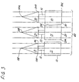
- FIG. 3 is an illustration of the pre-procedural alignment of three body elements during scanning.
- FIG. 4 is an illustration of the intra-procedural alignment of the three body elements of FIG. 3 during surgery.
- FIG. 5 is an illustration of three body elements, one of which has a reference frame attached thereto, in combination with a probe.
- FIG. 6 is an illustration showing ultrasound registration according to the invention in which emitters are attached to the patient's body.
- FIG. 7 is an illustration of a fluoroscopic localizer according to the invention for providing projections of an image of the body elements.
- FIG. 8 is an illustration of a drill guide instrument of the invention wherein the position of a drill guide relative to the body elements may be displayed.
- FIGS. 9 and 10 illustrate a clamped reference frame and a wired reference frame, respectively.
- FIG. 2A an overview of operation of one preferred embodiment of the system according to the invention is illustrated.
- the body elements which will be part of the procedure are scanned to determine their alignment.
- the alignment may be such as illustrated in FIG. 3 wherein body elements 10 , 20 , and 30 are more or less aligned in parallel.
- These body elements may be bones or other rigid bodies.
- three-dimensional skeletal elements 10 , 20 , 30 are depicted in two dimensions as highly stylized vertebral bodies, with square vertebra 11 , 21 , 31 , small rectangular pedicles 12 , 22 , 32 , and triangular spinous processes 13 , 23 , 33 .
- scans are taken at intervals through the body parts 10 , 20 , 30 as represented in FIG. 3 by nine straight lines generally referred to be reference character 40 . At least one scan must be obtained through each of the body elements and the scans taken together constitute a three-dimensional pre-procedural image data set.
- FIG. 2B is a block diagram of the system according to the invention.
- a scanner interface 102 allows a processor 104 to obtain the pre-procedural image data set generated by the scanner and store the data set in pre-procedural image data set memory 106 .
- processor 104 applies a discrimination process to the pre-procedural image data set so that only the body elements 10 , 20 , 30 remain in memory 106 .
- processor 104 may execute the discrimination process while data is being transferred from the scanner through the scanner interface 102 for storage in memory 106 .
- memory 106 may be used for storing undiscriminated data and a separate memory (not shown) may be provided for storing the discriminated data.
- processor 104 would transfer the data set from the scanner through scanner interface 102 into memory 106 and then would discriminate the data stored in memory 106 to generate a discriminated image data set which would be stored in the separate memory.
- the body elements 10 , 20 , 30 are discriminated from the soft tissue and each defined as a single rigid body, they can be repositioned by software algorithms, well known in the art, to form the displaced image data set.
- Each of the body elements 10 , 20 , 30 must have at least three reference points which are selected by the doctor or surgeon and which are visible on the pre-procedural images. These reference points must be able to be indicated with accuracy during the procedure.
- reference points 10 A, 10 B, and 10 C are located on the spinous process 13 ; for body part 20 , reference points 20 A and 20 C are located on the vertebra 21 and reference point 20 B is located on spinous process 23 ; and for body part 30 , reference points 30 A and 30 B are located on the spinous process 33 and reference point 30 C is located on the vertebra 31 . More than one reference point can be selected on each scan through the bone, although the maximal accuracy of registration is achieved by separating the reference points as far as possible. For example, in the case of posterior spinal surgery, it may be preferable to select reference points 10 A, 10 B, and 10 C on the spinous process which is routinely exposed during such surgery.
- work station software may allow the manual or automated identification of these same points on the images of the body elements 10 , 20 , 30 .
- FIG. 3 is a two-dimensional simplification of a three-dimension process, the reference points will not necessarily be limited to a perfect sagittal plane, as depicted.
- the skeletal body elements 10 , 20 , 30 may move with respect to each other at the joints or fracture lines.
- the procedure room such as an operating room or a room where a medical procedure will be performed
- the body elements will assume a different geometry, such as the geometry depicted in FIG. 4 .
- the pre-procedural image data set stored in memory 106 consisting of the scans through the skeletal elements, does not depict the operative position of the skeletal elements, as shown in FIG. 4 .
- the shape of the skeletal elements, as depicted by the scans through the element is consistent between imaging and procedure, as indicated by the lines 40 through each element in FIG. 4 . Therefore, the image data set must be modified to depict the current geometry of the skeletal elements. This modification is performed by identifying the location of each reference point of each skeletal element in procedure space. As diagrammatically illustrated in FIG.
- a localizer 108 identifies the location and provides this information so that the pre-procedural data set may be deformed or re-positioned into the displaced data set. As a result, the displaced data set is in registration with the intra-procedural position of the elements 10 , 20 , 30 .
- processor 104 which is a part of the work station, can execute software which re-positions the images of the skeletal elements to reflect the position of the actual elements in the procedure room thus forming the displaced set and the registration between the displaced set and the intra-procedural position.
- a three-dimensional digitizer may be used as the localizer 108 to determine the position and space of the elements 10 , 20 , 30 during the procedure.
- the digitizer would include a reference array 110 which receives emissions from a series of emitters.
- the emissions consist of some sort of energy, such as light, sound or electromagnetic radiation.
- the emitters are applied to and positioned in coordination with the elements being localized and the reference array 110 is distant therefrom, determining the position of the emitters.
- the emitters may be placed distant to the elements and the reference array 110 may be attached to the elements being localized.
- a reference frame 116 is attached to one of the skeletal elements 10 at the beginning of the procedure.
- Reference frame 116 is equipped with a plurality of emitters 114 which together define a three-dimensional procedural coordinate system with respect to the skeletal element 10 .
- Emitters 114 communicate with sensors 112 on a reference array 110 located in the procedure room and remote from the reference frame 116 and patient. If the body of the patient is not immobilized during surgery, then multiple reference frames may be required.
- the three-dimensional procedural coordinate system may alternatively be defined by rigid fixation of the frame emitters 114 directly (or indirectly, for example, to the skin) to the skeletal elements 10 , 20 , or 30 .
- the emitters 114 emit a signal which is received by the sensors 112 .
- the received signal is digitized to compute position, for example, by triangulation.
- the localizer 108 or a digitizer which is part of the localizer 108 can determine the exact three-dimensional position of the frame emitters 114 relative to the sensors 112 .
- the sensors 112 are in a fixed position throughout the procedure, as the reference array 110 is fixed in the procedure room to the ceiling or other support. Thereby, localizer 108 or the processor 104 can exactly determine the position of the reference frame 116 relative to the array.
- the reference frame 116 is free to move except during localization, e.g., activation of the emitters 114 on the reference frame 116 and activation of the probe emitters 120 .
- Emitters 114 of the reference frame 116 are energized to provide radiation to the sensors 112 , which radiation is received and generates signals provided to the localizer 108 for determining the position of the frame 116 relative to the array 110 .
- the position of the skeletal element 10 to which the reference frame 116 is affixed must be determined.
- the reference points are touched by the tip of a probe 118 equipped with emitters 120 .
- the emitters are energized to communicate with the sensors 112 of reference array 110 . This communication permits the localizer 108 to determine the position of the probe 118 , thereby determining the position of the tip of the probe 118 , thereby determining the position of the reference point 10 A on which the tip is positioned.
- an intra-procedural position data is generated and stored in memory 121 .
- This data is used to derive a transformation which allows the determination of the exact procedural position and orientation of each skeletal element.
- localizer 108 and processor 104 employ software which manipulates the pre-procedural image data set stored in memory 106 to produce a displaced image data set which is stored in memory 122 .
- the displaced image data set in memory 122 reflects the geometry of the actual elements 10 , 20 , 30 during the procedure.
- Processor 104 displays the displaced image data set on display 124 to provide a visual depiction of the relative position of the skeletal elements 10 , 20 , 30 during the procedure. This image is used by the doctor during the procedure to assist in the procedure.
- an instrument which would be used during the procedure may be modified by the addition of emitters. This modified instrument when moved into the area of the skeletal elements 10 , 20 , 30 would be activated so that its emitters would communicate with the reference array 110 thereby permitting localizer 108 to determine the instrument's position.
- processor 104 would modify display 124 to indicate the position of the instrument, such as by positioning a cursor.
- Reference frame 116 allows the patient to be moved during the procedure without the need for re-registering the position of each of the body elements 10 , 20 , 30 . It is assumed that during the procedure, the patient is immobilized so that the body elements are fixed relative to each other. Since the reference frame 116 is affixed to skeletal element 10 , movement of the patient results in corresponding movement of the reference frame 116 . Periodically, or after each movement of the patient, array emitters 114 may be energized to communicate with the sensors 112 of reference array 110 in order to permit localizer 108 to determine the position of the reference frame 116 .
- localizer 108 and/or processor 104 can determine the position of the elements. From this position, a displaced image data set memory can be created for display on display 124 .
- An alternative to touching the reference points A, B, C with the tip of the probe 118 would be to use a contour scanner 126 .
- a contour scanner 126 Such a device, using some form of energy such as sound or light which is emitted, reflected by the contour and sensed, would allow the extraction of a contour of the skeletal elements 10 , 20 , 30 , thus serving as a multitude of reference points which would allow registration to occur.
- the registration process is analogous to the process described for ultrasound extracted contours below.
- markers may be used on the skin surface as reference points to allow the transformation of the pre-procedural image data set into the displaced image data set.
- skin surface fiducials applied at the time of imaging can be used to re-position the body to match the geometry during imaging and is described below.
- Localization of skeletal elements 10 , 20 , 30 may be desired without intra-procedural exposure of the reference points A, B, C on those skeletal elements.
- Examples wherein the spine is minimally exposed include percutaneous biopsy of the spine or discectomy, spinal fixation, endoscopy, percutaneous spinal implant insertion, percutaneous fusion, and insertion of drug delivery systems.
- localization of reference points on the skeletal elements must be determined by some form of imaging which can localize through overlying soft tissue.
- imaging techniques which are available to a surgeon in the operating room or a doctor in a procedure room which satisfy the needs of being low cost and portable. Both imaging techniques, ultrasonography and radiography, can produce two- or three-dimensional images which can be employed in the fashion described herein to register a three-dimensional form such as a skeletal element.
- the coupling of a three-dimensional digitizer to a probe of an ultrasound device affords benefits in that a contour can be obtained which can be related directly to a reference system that defines three-dimensional coordinates in the procedural work space.
- a patient is imaged prior to a procedure to generate a pre-procedural image data set which is stored in memory 106 .
- the patient's body is immobilized to stabilize the spatial relationship between the skeletal elements 10 , 20 , 30 .
- a reference system for the body is established by attaching a reference array 110 to one of the skeletal elements or by otherwise attaching emitters to the patient or skeletal elements as noted above. For example, this could be performed by using the percutaneous placement of a reference system similar to the one described above, radiopaque markers screwed into the elements or by placing emitters 130 directly on the skins, as illustrated in FIG. 6 , based on the assumption that the skin does not move appreciably during the procedure or in respect to the axial skeleton.
- An ultrasound probe 128 equipped with at least three emitters 130 is then placed over the skeletal element of interest.
- the contour (which can be either two- or three-dimensional) of the underlying bone/soft tissue interface is then obtained using the ultrasound probe 128 .
- This contour of the underlying bone can be expressed directly or indirectly in the procedural coordinates defined by the reference system.
- Emitters 130 communicate with sensors 112 of reference array 110 to indicate the position of the ultrasound probe 128 .
- An ultrasound scanner 131 which energizes probe 128 determines the contour of the skeletal element of interest being scanned. This contour information is provided to processor 104 for storage in contour memory 132 .
- the intra-procedural contour stored in memory 132 is then compared by a contour matching algorithm to a corresponding contour extracted from the pre-operative image data set stored in memory 106 .
- a pre-procedural contour data set may be stored in memory 134 based on a pre-procedural ultrasound scan which is input into memory 134 via scanner interface 102 prior to the procedure. This comparison process continues until a match is found for each one of the elements. Through this contour matching process, a registration is obtained between the images of each skeletal element and the corresponding position of each element in the procedural space.
- the ultrasound registration noted above may not be applicable.
- ultrasound does not penetrate bone, and the presence of overlying bone would preclude the registration of an underlying skeletal element.
- the resolution of ultrasound declines as the depth of the tissue being imaged increases and may not be useful when the skeletal element is so deep as to preclude obtaining an accurate ultrasonically generated contour.
- a radiological method is indicated, which utilizes the greater penetrating power of x-rays.
- Pre-operative imaging occurs as usual and the skeletal elements are discriminated from the soft tissue in the image data set as above.
- a CT scan of the skeletal elements 10 , 20 , 30 is taken prior to the procedure.
- Processor 104 may then discriminate the skeletal elements.
- the patient is immobilized for the procedure.
- a radiograph of the skeletal anatomy of interest is taken by a radiographic device equipped with emitters detectible by the digitizer.
- a fluoroscopic localizer 136 is illustrated in FIG. 7 .
- Localizer 136 includes a device which emits x-rays such as tube 138 and a screen 140 which is sensitive to x-rays, producing an image when x-rays pass through it.
- this screen is referred to as a fluoroscopic plate.
- Emitters 142 may be positioned on the tube 138 , or on the fluoroscopic plate 140 or on both.
- the reference array 110 may be attached to the tube or the plate.
- Fluoroscopic localizer 136 includes a processor which digitizes the image on the plate 140 and provides the digitized image to processor 104 for storage in memory 106 .
- Processor 104 may simulate the generation of this two-dimensional x-ray image by creating a two-dimensional projection of the three-dimensional skeletal elements that have been discriminated in the image data set stored in memory 106 .
- an iterative process is used which re-positions the images of the skeletal elements such that a two-dimensional projection through the displaced data set matches the actual radiographic image.
- the described process can utilize more than one radiographic image. Since the processor 104 is also aware of the position of the fluoroscopic localizers because of the emitters 142 thereon, which are in communication with localizer 108 , the exact position of the skeletal elements during the procedure is determined.
- the above solutions achieve registration by the formation of a displaced image data set stored in memory 122 which matches the displacement of the skeletal elements at the time of the procedure.
- An alternative technique to achieve registration is to ensure that the positions of the skeletal elements during the procedure are identical to that found at the time of imaging. This can be achieved by using a frame that adjusts and immobilizes the patient's position.
- at least three markers are placed on the skin prior to imaging. These markers have to be detectible by the imaging technique employed and are called fiducials. A multiplicity of fiducials is desirable for improving accuracy.
- the patient's body is placed on a frame that allows precise positioning.
- Such frames are commonly used for spinal surgery and could be modified to allow their use during imaging and could be used for repositioning the patient during the procedure.
- These frames could be equipped with drive mechanisms that allow the body to be moved slowly through a variety of positions.
- the fiducials placed at the time of imaging are replaced by emitters. By activating the drive mechanism on the frame, the exact position of the emitters can be determined during the procedure and compared to the position of the fiducials on the pre-procedural image data set stored in memory 106 .
- the emitters assume a geometry identical to the geometry of the fiducials of the image data set, it is considered that the skeletal elements will have resumed a geometric relationship identical to the position during the pre-procedural scan, and the procedure can be performed using the unaltered image data set stored in memory 106 .
- instrumentation employed during procedures on the skeleton is somewhat different than that used for cranial applications. Rather than being concerned with the current location, surgery on the skeleton usually consists of placing hardware through bones, taking a biopsy through the bone, or removing fragments. Therefore, the instrumentation has to be specialized for this application.
- One instrument that is used commonly is a drill.
- a drill By placing emitters on a surgical drill, and by having a fixed relationship between the drill body and its tip (usually a drill bit), the direction and position of the drill bit can be determined. At least three emitters would be needed on the drill, as most drills have a complex three-dimensional shape.
- emitters could be placed on a drill guide tube 800 having emitters 802 , and the direction 804 of the screw being placed or hole being made could be determined by the digitizer and indicated on the image data set (see FIG. 8 ).
- the skeletal element 806 would also have emitters thereon to indicate its position.
- a clamp like arrangement for open surgery, a clamp like arrangement, as depicted in FIG. 9 , can be used.
- a clamp 900 is equipped with at least two points 902 , 904 , 906 , 908 which provide fixation to a projection 910 of a skeletal element.
- the clamp includes emitters 912 , 914 , 916 which communicate with the array to indicate the position of the skeletal element as it is moved during the procedure.
- FIG. 10 depicts a reference platform 956 attached to such wires or screws 950 , 952 projecting through the skin 954 .
- the platform 956 includes a plurality of emitters 958 , 960 , 962 , 964 which communicate with the array to indicate the position of the bone fragment 940 as it is moved during the procedure.
- the reference frame can be slipped over or attached to the projecting screws or wires to establish a reference system.
- the frame can be attached to only one wire, as long as the method of attachment of the frame to the screw or wire prevents rotation, and that the wire or screw cannot rotate within the attached skeletal element.
Abstract
A system for use during a medical or surgical procedure on a body. The system modifies a reference image data set according to a density image of a body element during a procedure, generates a displaced image data set representing the position and geometry of the body element during the procedure, and compares the density image of the body element during the procedure to the reference image of the body element. The system also includes a display utilizing the displaced image data set generated by the processor to illustrate the position and geometry of the body element during the procedure. Methods relating to the system are also disclosed.
Description
This application is a continuation of U.S. patent application Ser. No. 10/198,324, filed Jul. 18, 2002, now U.S. Pat. No. 6,978,166, which is a continuation of U.S. patent application Ser. No. 09/398,313, filed on Sep. 20, 1999, now U.S. Pat. No. 6,434,415, which is a continuation of U.S. patent application Ser. No. 08/931,654 filed on Sep. 16, 1997, now U.S. Pat. No. 6,347,240, which is a continuation of U.S. patent application Ser. No. 08/319,615, filed on Oct. 7, 1994, now abandoned.
The invention relates generally to systems which generate images during medical and surgical procedures, and in particular, a system for generating images during medical and surgical procedures based on a scan taken prior to the procedure.
Image guided medical and surgical procedures comprise a technology by which images, obtained either pre-procedurally or intra-procedurally (i.e., prior to or during a medical or surgical procedure), are used to guide a doctor during the procedure. The recent increase in interest in this field is a direct result of the recent advances in imaging technology, especially in devices using computers to generate three dimensional images of parts of the body, such as computed tomography (CT) or magnetic resonance imaging (MRI).
The majority of the advances in imaging involve devices which tend to be large, encircle the body part being imaged, and are expensive. Although the images produced by these devices depict the body part under investigation with high resolution and good spatial fidelity, their cost usually precludes the dedication of a unit to the performance of procedures. Therefore, image guided surgery is usually performed using images taken preoperatively.
The reliance upon preoperative images has focused image guidance largely to the cranium. The skull, by encasing the brain, serves as a vessel which inhibits changes in anatomy between imaging and surgery. The skull also provides a relatively easy point of reference to which a localization system may be attached so that registration of pre-procedural images to the procedural work space can be done simply at the beginning of the procedure. Registration is defined as the process of relating pre-procedural images of anatomy to the surgical or medical position of the corresponding anatomy. For example, see Ser. No. 07/909,097, now U.S. Pat. No. 5,383,454, the entire disclosure of which is incorporated herein by reference.
This situation of rigid fixation and absence of anatomical movement between imaging and surgery is unique to the skull and intracranial contents and permits a one-to-one registration process as shown in FIG. 1 . The position during a medical procedure or surgery is in registration with the pre-procedural image data set because of the absence of anatomical movement from the time of the scan until the time of the procedure. In almost every other part of the body there is ample opportunity for movement which degrades the fidelity of the pre-procedural images in depicting the intra-procedural anatomy. Therefore, additional innovations are needed to bring image guidance to the rest of the body beyond the cranium.
The accuracy of image guided surgery is based on the identification of structures within the body that do not change shape, do not compress, nor deform between the process of imaging and surgery. Such structures are termed “rigid bodies,” and the bones of the skeleton satisfy this definition for a rigid body. Bones are commonly a target for medical or surgical procedures either for repair, fusion, or biopsy. Therefore, a technique is needed whereby registration can be performed between the bones or bone fragments (skeletal elements) as depicted pre-procedurally on scans and the position of these same skeletal elements as detected intra-procedurally. This technique must take into account that movement can occur between portions of the skeleton which are not rigidly joined, such as bones connected by a joint, or fragments of a broken bone.
It is an object of this invention to provide a system which allows registration between multiple skeletal elements depicted in pre-procedural images and detected during surgery.
It is a further object of this invention to provide a system which can localize multiple rigid bodies that move with respect to each other between imaging and a procedure and provide a display during the procedure of the bodies in their displaced positions.
It is another object of this invention to provide a system for use during a medical or surgical procedure on the body, the system generating a display representing the position of two or more body elements during the procedure based on an image data set generated by a scanner prior to the procedure.
It is another object of this invention to provide a system for use during a medical or surgical procedure on a body which modifies the image data set according to the identified relative position of each of the elements during the procedure.
It is another object of this invention to provide a system which generates a display representative of the position of a medical or surgical instrument during a procedure in relation to body elements.
It is a further object of this invention to provide a system for use during image guided medical and surgical procedures which is easily employed by the doctor or surgeon conducting the procedure.
It is another object of this invention to provide a system which determines the relative position of body elements based on the contour of the body elements which, in some cases, avoids the need for exposing the body elements.
It is still another object of this invention to provide a system which employs the projected fluoroscopic images of body elements to determine their relative position.
It is yet a further object of this invention to describe a surgical or medical procedure which employs a display representing the position of body elements during the procedure based on an image data set of the body elements generated prior to the procedure.
It is a further object of this invention to provide a system and method for medical or surgical procedures which allows repositioning of body elements during the procedure and still permits the generation of a display showing the relative position of the body elements.
Other objects and features will be in part apparent and in part pointed out hereinafter.
The invention comprises a system for use during a medical or surgical procedure on a body. The system generates a display representing the position of two or more body elements during the procedure based on an image data set generated by a scanner prior to the procedure, the image data set having reference points for each of the body elements. The reference points of a particular body element have a fixed spatial relation to the particular body element. The system includes means for identifying, during the procedure, the relative position of each of the reference points of each of the body elements to be displayed. The system also includes a processor modifying the image data set according to the identified relative position of each of the reference points during the procedure, as identified by the identifying means. The processor generates a displaced image data set representing the position of the body elements during the procedure. The system also includes a display utilizing the displaced image data set generated by the processor and illustrating the relative position of the body elements during the procedure.
The invention also comprises a method for use during a procedure. The method generates a display representing the position of two or more body elements during the procedure based on an image data set generated prior to the procedure, which image data set has reference points for each of the body elements. The method comprises the steps of:
identifying, during the procedure, the relative position of each of the reference points of each of the body elements to be displayed;
modifying the image data set according to the identified relative position of each of the reference points during the procedure in order to generate a displaced image data set representing the position of the body elements during the procedure; and
generating a display based on the displaced image data set illustrating the relative position of the body elements during the procedure.
The invention also comprises a method for use with two or more body elements which each have reference points. The method comprises the steps of:
prior to a procedure:
placing the body elements in a frame to fix their relative position; and
scanning the fixed body elements; and
during the procedure:
placing the body elements in the frame so that the body elements have the same relative position as their position during scanning;
determining the position of reference points on the body elements relative to reference means;
determining the position of a medical or surgical instrument relative to the reference means;
determining the position of the medical or surgical instrument relative to the body elements; and
generating a display based on the pre-procedural scanning illustrating the determined position of the medical or surgical instrument relative to the body elements.
Corresponding reference characters indicate corresponding parts throughout the drawings.
Referring to FIG. 2A , an overview of operation of one preferred embodiment of the system according to the invention is illustrated. Prior to a particular procedure, the body elements which will be part of the procedure are scanned to determine their alignment. For example, the alignment may be such as illustrated in FIG. 3 wherein body elements 10, 20, and 30 are more or less aligned in parallel. These body elements may be bones or other rigid bodies. In FIG. 3 , three-dimensional skeletal elements 10, 20, 30 are depicted in two dimensions as highly stylized vertebral bodies, with square vertebra 11, 21, 31, small rectangular pedicles 12, 22, 32, and triangular spinous processes 13, 23, 33. During imaging, scans are taken at intervals through the body parts 10, 20, 30 as represented in FIG. 3 by nine straight lines generally referred to be reference character 40. At least one scan must be obtained through each of the body elements and the scans taken together constitute a three-dimensional pre-procedural image data set.
Once the body elements 10, 20, 30 are discriminated from the soft tissue and each defined as a single rigid body, they can be repositioned by software algorithms, well known in the art, to form the displaced image data set. Each of the body elements 10, 20, 30 must have at least three reference points which are selected by the doctor or surgeon and which are visible on the pre-procedural images. These reference points must be able to be indicated with accuracy during the procedure. For body part 10, reference points 10A, 10B, and 10C are located on the spinous process 13; for body part 20, reference points 20A and 20C are located on the vertebra 21 and reference point 20B is located on spinous process 23; and for body part 30, reference points 30A and 30B are located on the spinous process 33 and reference point 30C is located on the vertebra 31. More than one reference point can be selected on each scan through the bone, although the maximal accuracy of registration is achieved by separating the reference points as far as possible. For example, in the case of posterior spinal surgery, it may be preferable to select reference points 10A, 10B, and 10C on the spinous process which is routinely exposed during such surgery. It is contemplated that work station software may allow the manual or automated identification of these same points on the images of the body elements 10, 20, 30. As FIG. 3 is a two-dimensional simplification of a three-dimension process, the reference points will not necessarily be limited to a perfect sagittal plane, as depicted.
After imaging, the skeletal body elements 10, 20, 30 may move with respect to each other at the joints or fracture lines. In the procedure room, such as an operating room or a room where a medical procedure will be performed, after positioning the patient for surgery, the body elements will assume a different geometry, such as the geometry depicted in FIG. 4 .
As a result of this movement, the pre-procedural image data set stored in memory 106, consisting of the scans through the skeletal elements, does not depict the operative position of the skeletal elements, as shown in FIG. 4 . However, the shape of the skeletal elements, as depicted by the scans through the element, is consistent between imaging and procedure, as indicated by the lines 40 through each element in FIG. 4 . Therefore, the image data set must be modified to depict the current geometry of the skeletal elements. This modification is performed by identifying the location of each reference point of each skeletal element in procedure space. As diagrammatically illustrated in FIG. 2B , a localizer 108 identifies the location and provides this information so that the pre-procedural data set may be deformed or re-positioned into the displaced data set. As a result, the displaced data set is in registration with the intra-procedural position of the elements 10, 20, 30. Once the locations of the reference points are determined by the localizer 108, processor 104, which is a part of the work station, can execute software which re-positions the images of the skeletal elements to reflect the position of the actual elements in the procedure room thus forming the displaced set and the registration between the displaced set and the intra-procedural position.
Preferably, a three-dimensional digitizer may be used as the localizer 108 to determine the position and space of the elements 10, 20, 30 during the procedure. In general, the digitizer would include a reference array 110 which receives emissions from a series of emitters. Usually, the emissions consist of some sort of energy, such as light, sound or electromagnetic radiation. The emitters are applied to and positioned in coordination with the elements being localized and the reference array 110 is distant therefrom, determining the position of the emitters. As is apparent, the emitters may be placed distant to the elements and the reference array 110 may be attached to the elements being localized.
According to one preferred embodiment of the invention as shown in FIG. 5 , a reference frame 116 is attached to one of the skeletal elements 10 at the beginning of the procedure. Reference frame 116 is equipped with a plurality of emitters 114 which together define a three-dimensional procedural coordinate system with respect to the skeletal element 10. Emitters 114 communicate with sensors 112 on a reference array 110 located in the procedure room and remote from the reference frame 116 and patient. If the body of the patient is not immobilized during surgery, then multiple reference frames may be required. The three-dimensional procedural coordinate system may alternatively be defined by rigid fixation of the frame emitters 114 directly (or indirectly, for example, to the skin) to the skeletal elements 10, 20, or 30. In either case, the emitters 114 emit a signal which is received by the sensors 112. The received signal is digitized to compute position, for example, by triangulation. Through such information, the localizer 108 or a digitizer which is part of the localizer 108 can determine the exact three-dimensional position of the frame emitters 114 relative to the sensors 112. The sensors 112 are in a fixed position throughout the procedure, as the reference array 110 is fixed in the procedure room to the ceiling or other support. Thereby, localizer 108 or the processor 104 can exactly determine the position of the reference frame 116 relative to the array. The reference frame 116 is free to move except during localization, e.g., activation of the emitters 114 on the reference frame 116 and activation of the probe emitters 120. Emitters 114 of the reference frame 116 are energized to provide radiation to the sensors 112, which radiation is received and generates signals provided to the localizer 108 for determining the position of the frame 116 relative to the array 110.
Next, it is necessary to determine the position of the skeletal element 10 to which the reference frame 116 is affixed. In particular, the position of the skeletal element 10 relative to the reference frame 116 must be determined. After exposure of the reference points 10A, 10B, 10C by surgical dissection, the reference points are touched by the tip of a probe 118 equipped with emitters 120. As each of the reference points 10A, 10B, 10C is touched by the tip of the probe 118, the emitters are energized to communicate with the sensors 112 of reference array 110. This communication permits the localizer 108 to determine the position of the probe 118, thereby determining the position of the tip of the probe 118, thereby determining the position of the reference point 10A on which the tip is positioned. By touching each of the reference points 10A, 10B, 10C on each skeletal element 10, 20, 30 involved in the procedure, and relating them to their corresponding reference points on the images of the same elements, an intra-procedural position data is generated and stored in memory 121. This data is used to derive a transformation which allows the determination of the exact procedural position and orientation of each skeletal element. Using the intra-procedural position of the skeletal elements 10, 20, 30, localizer 108 and processor 104 employ software which manipulates the pre-procedural image data set stored in memory 106 to produce a displaced image data set which is stored in memory 122. The displaced image data set in memory 122 reflects the geometry of the actual elements 10, 20, 30 during the procedure. Processor 104 displays the displaced image data set on display 124 to provide a visual depiction of the relative position of the skeletal elements 10, 20, 30 during the procedure. This image is used by the doctor during the procedure to assist in the procedure. In addition, it is contemplated that an instrument which would be used during the procedure may be modified by the addition of emitters. This modified instrument when moved into the area of the skeletal elements 10, 20, 30 would be activated so that its emitters would communicate with the reference array 110 thereby permitting localizer 108 to determine the instrument's position. As a result, processor 104 would modify display 124 to indicate the position of the instrument, such as by positioning a cursor.
An alternative to touching the reference points A, B, C with the tip of the probe 118 would be to use a contour scanner 126. Such a device, using some form of energy such as sound or light which is emitted, reflected by the contour and sensed, would allow the extraction of a contour of the skeletal elements 10, 20, 30, thus serving as a multitude of reference points which would allow registration to occur. The registration process is analogous to the process described for ultrasound extracted contours below.
In certain situations, markers may be used on the skin surface as reference points to allow the transformation of the pre-procedural image data set into the displaced image data set. Reciprocally, skin surface fiducials applied at the time of imaging can be used to re-position the body to match the geometry during imaging and is described below.
Localization of skeletal elements 10, 20, 30 may be desired without intra-procedural exposure of the reference points A, B, C on those skeletal elements. Examples wherein the spine is minimally exposed include percutaneous biopsy of the spine or discectomy, spinal fixation, endoscopy, percutaneous spinal implant insertion, percutaneous fusion, and insertion of drug delivery systems. In this situation, localization of reference points on the skeletal elements must be determined by some form of imaging which can localize through overlying soft tissue. There are currently two imaging techniques which are available to a surgeon in the operating room or a doctor in a procedure room which satisfy the needs of being low cost and portable. Both imaging techniques, ultrasonography and radiography, can produce two- or three-dimensional images which can be employed in the fashion described herein to register a three-dimensional form such as a skeletal element.
As described in U.S. Pat. Nos. 5,851,183 and 5,871,445, the entire disclosures of which are incorporated herein by reference, the coupling of a three-dimensional digitizer to a probe of an ultrasound device affords benefits in that a contour can be obtained which can be related directly to a reference system that defines three-dimensional coordinates in the procedural work space. In the context of the present invention, a patient is imaged prior to a procedure to generate a pre-procedural image data set which is stored in memory 106. In the procedure room, the patient's body is immobilized to stabilize the spatial relationship between the skeletal elements 10, 20, 30. A reference system for the body is established by attaching a reference array 110 to one of the skeletal elements or by otherwise attaching emitters to the patient or skeletal elements as noted above. For example, this could be performed by using the percutaneous placement of a reference system similar to the one described above, radiopaque markers screwed into the elements or by placing emitters 130 directly on the skins, as illustrated in FIG. 6 , based on the assumption that the skin does not move appreciably during the procedure or in respect to the axial skeleton.
An ultrasound probe 128 equipped with at least three emitters 130 is then placed over the skeletal element of interest. The contour (which can be either two- or three-dimensional) of the underlying bone/soft tissue interface is then obtained using the ultrasound probe 128. This contour of the underlying bone can be expressed directly or indirectly in the procedural coordinates defined by the reference system. Emitters 130 communicate with sensors 112 of reference array 110 to indicate the position of the ultrasound probe 128. An ultrasound scanner 131 which energizes probe 128 determines the contour of the skeletal element of interest being scanned. This contour information is provided to processor 104 for storage in contour memory 132.
The intra-procedural contour stored in memory 132 is then compared by a contour matching algorithm to a corresponding contour extracted from the pre-operative image data set stored in memory 106. Alternatively, a pre-procedural contour data set may be stored in memory 134 based on a pre-procedural ultrasound scan which is input into memory 134 via scanner interface 102 prior to the procedure. This comparison process continues until a match is found for each one of the elements. Through this contour matching process, a registration is obtained between the images of each skeletal element and the corresponding position of each element in the procedural space.
In certain instances, the ultrasound registration noted above may not be applicable. For example, ultrasound does not penetrate bone, and the presence of overlying bone would preclude the registration of an underlying skeletal element. Further, the resolution of ultrasound declines as the depth of the tissue being imaged increases and may not be useful when the skeletal element is so deep as to preclude obtaining an accurate ultrasonically generated contour. In these circumstances, a radiological method is indicated, which utilizes the greater penetrating power of x-rays.
Pre-operative imaging occurs as usual and the skeletal elements are discriminated from the soft tissue in the image data set as above. In particular, a CT scan of the skeletal elements 10, 20, 30 is taken prior to the procedure. Processor 104 may then discriminate the skeletal elements. Next, the patient is immobilized for the procedure. A radiograph of the skeletal anatomy of interest is taken by a radiographic device equipped with emitters detectible by the digitizer. For example, a fluoroscopic localizer 136 is illustrated in FIG. 7 . Localizer 136 includes a device which emits x-rays such as tube 138 and a screen 140 which is sensitive to x-rays, producing an image when x-rays pass through it. In general, this screen is referred to as a fluoroscopic plate. Emitters 142 may be positioned on the tube 138, or on the fluoroscopic plate 140 or on both. For devices in which the tube 138 is rigidly supported relative to the plate 140, emitters need only be provided on either the tube or the plate. Alternatively, the reference array 110 may be attached to the tube or the plate. By passing x-rays through the skeletal element 141 of interest, a two-dimensional image based on bone density is produced and recorded by the plate. The image produced by the fluoroscopic localizer 136 is determined by the angle of the tube 138 with respect to the plate 140 and the position of the skeletal elements therebetween. Fluoroscopic localizer 136 includes a processor which digitizes the image on the plate 140 and provides the digitized image to processor 104 for storage in memory 106. Processor 104 may simulate the generation of this two-dimensional x-ray image by creating a two-dimensional projection of the three-dimensional skeletal elements that have been discriminated in the image data set stored in memory 106. In order to form the displaced data set and thus achieve registration, an iterative process is used which re-positions the images of the skeletal elements such that a two-dimensional projection through the displaced data set matches the actual radiographic image. The described process can utilize more than one radiographic image. Since the processor 104 is also aware of the position of the fluoroscopic localizers because of the emitters 142 thereon, which are in communication with localizer 108, the exact position of the skeletal elements during the procedure is determined.
The above solutions achieve registration by the formation of a displaced image data set stored in memory 122 which matches the displacement of the skeletal elements at the time of the procedure. An alternative technique to achieve registration is to ensure that the positions of the skeletal elements during the procedure are identical to that found at the time of imaging. This can be achieved by using a frame that adjusts and immobilizes the patient's position. In this technique, at least three markers are placed on the skin prior to imaging. These markers have to be detectible by the imaging technique employed and are called fiducials. A multiplicity of fiducials is desirable for improving accuracy.
During the procedure, the patient's body is placed on a frame that allows precise positioning. Such frames are commonly used for spinal surgery and could be modified to allow their use during imaging and could be used for repositioning the patient during the procedure. These frames could be equipped with drive mechanisms that allow the body to be moved slowly through a variety of positions. The fiducials placed at the time of imaging are replaced by emitters. By activating the drive mechanism on the frame, the exact position of the emitters can be determined during the procedure and compared to the position of the fiducials on the pre-procedural image data set stored in memory 106. Once the emitters assume a geometry identical to the geometry of the fiducials of the image data set, it is considered that the skeletal elements will have resumed a geometric relationship identical to the position during the pre-procedural scan, and the procedure can be performed using the unaltered image data set stored in memory 106.
In general, instrumentation employed during procedures on the skeleton is somewhat different than that used for cranial applications. Rather than being concerned with the current location, surgery on the skeleton usually consists of placing hardware through bones, taking a biopsy through the bone, or removing fragments. Therefore, the instrumentation has to be specialized for this application.
One instrument that is used commonly is a drill. By placing emitters on a surgical drill, and by having a fixed relationship between the drill body and its tip (usually a drill bit), the direction and position of the drill bit can be determined. At least three emitters would be needed on the drill, as most drills have a complex three-dimensional shape. Alternatively, emitters could be placed on a drill guide tube 800 having emitters 802, and the direction 804 of the screw being placed or hole being made could be determined by the digitizer and indicated on the image data set (see FIG. 8 ). The skeletal element 806 would also have emitters thereon to indicate its position.
Besides modification of existing instrumentation, new instrumentation is required to provide a reference system for surgery as discussed above. These reference frames, each equipped with at least 3 emitters, require fixation to the bone which prevents movement or rotation.
For open surgery, a clamp like arrangement, as depicted in FIG. 9 , can be used. A clamp 900 is equipped with at least two points 902, 904, 906, 908 which provide fixation to a projection 910 of a skeletal element. By using at least two point fixation the clamp 900, which functions as a reference frame, will not rotate with respect to the skeletal element. The clamp includes emitters 912, 914, 916 which communicate with the array to indicate the position of the skeletal element as it is moved during the procedure.
Many procedures deal with bone fragments 940 which are not exposed during surgery, but simply fixated with either wires or screws 950, 952 introduced through the skin 954. FIG. 10 depicts a reference platform 956 attached to such wires or screws 950, 952 projecting through the skin 954. The platform 956 includes a plurality of emitters 958, 960, 962, 964 which communicate with the array to indicate the position of the bone fragment 940 as it is moved during the procedure.
The reference frame can be slipped over or attached to the projecting screws or wires to establish a reference system. Alternatively, the frame can be attached to only one wire, as long as the method of attachment of the frame to the screw or wire prevents rotation, and that the wire or screw cannot rotate within the attached skeletal element.
In view of the above, it will be seen that the several objects of the invention are achieved and other advantageous results attained.
As various changes could be made in the above without departing from the scope of the invention, it is intended that all matter contained in the above description and shown in the accompanying drawings shall be interpreted as illustrative and not in a limiting sense.
Claims (40)
1. A system for use during a medical or surgical procedure on a portion of a body, said system for use with a discriminated image data set identifying skeletal elements of the portion of the body and representing a position and a geometry of the skeletal elements of the portion of the body; said system comprising:
a memory for storing the discriminated image data set;
an imaging device for producing, during the procedure, a density image of the portion of the body;
a processor modifying the discriminated image data set stored in the memory according to the density image, said processor generating a displaced image data set representing the position and geometry of the skeletal elements of the portion of the body during the procedure; and
a display utilizing the displaced image data set illustrating the position and geometry of the skeletal elements of the portion of the body during the procedure.
2. The system of claim 1 wherein the imaging device comprises a reference array for providing a reference and a device for determining the position of one or more reference points of the body element to be displayed relative to the reference array.
3. The system of claim 2 wherein the imaging device is a radiographic device.
4. The system of claim 3 wherein the radiographic device is a fluoroscopic device comprising a fluoroscopic tube and a fluoroscopic plate.
5. The system of claim 4 wherein the fluoroscopic tube is fixed in relation to the fluoroscopic plate so that a particular portion of the body may be positioned therebetween for producing the density image of such particular portion of the body during the procedure and wherein the processor compares the density image of such particular portion of the body during the procedure to the position of the skeletal elements of the portion of the body as represented by the discriminated image data set.
6. The system of claim 4 wherein the fluoroscopic tube is fixed in relation to a fluoroscopic plate so that a particular portion of the body may be positioned therebetween for producing the density image of such particular portion of the body during the procedure and wherein the processor compares the density image of such particular portion of the body during the procedure to the geometry of the skeletal elements of the portion of the body as represented by the discriminated image data set.
7. The system of claim 4 wherein said fluoroscopic tube has sensors thereon in communication with the reference array and wherein the determining device is adapted to determine the position of the tube relative to the reference array whereby the position of the density image of the portion of the body can be determined.
8. The system of claim 4 wherein said fluoroscopic plate has sensors thereon in communication with the reference array and wherein the determining device is adapted to determine the position of the plate relative to the reference array whereby the position of the density image of the portion of the body can be determined.
9. The system of claim 4 wherein said reference array has sensors thereon in communication with the fluoroscopic device and wherein the determining device is adapted to determine the position of the fluoroscopic device relative to the reference array whereby the position of the density image of the portion of the body can be determined.
10. The system of claim 1 wherein the imaging device is a radiographic device.
11. The system of claim 10 wherein the radiographic device is a fluoroscopic device comprising a fluoroscopic tube and a fluoroscopic plate.
12. The system of claim 11 wherein the fluoroscopic tube is fixed in relation to the fluoroscopic plate so that a particular portion of the body may be positioned therebetween for producing the density image of such particular portion of the body during the procedure and wherein the processor compares the density image of such particular portion of the body during the procedure to the position of the skeletal elements of the portion of the body as represented by the discriminated image data set.
13. The system of claim 11 wherein the fluoroscopic tube is fixed in relation to a fluoroscopic plate so that a particular portion of the body may be positioned therebetween for producing the density image of such particular portion of the body during the procedure and wherein the processor compares the density image of such particular portion of the body during the procedure to the geometry of the skeletal elements of the portion of the body as represented by the discriminated image data set.
14. The system of claim 11 wherein said fluoroscopic tube has sensors thereon in communication with the reference array and wherein the determining device is adapted to determine the position of the tube relative to the reference array whereby the position of the density image of the portion of the body can be determined.
15. The system of claim 11 wherein said fluoroscopic plate has sensors thereon in communication with the reference array and wherein the determining device is adapted to determine the position of the plate relative to the reference array whereby the position of the density image of the portion of the body can be determined.
16. The system of claim 1 wherein the processor modifies the discriminated image data set to generate the displaced data set using an iterative process such that a two-dimensional projection through the displaced image data set matches the density image during the procedure.
17. A system for displaying relative positions of first and second body portions during a procedure on a body, the system for use with a discriminated image data subset representing a position and geometry of the first and second body portions; said image data subset defining a position and geometry of the first and second body portions, the image data subset further having a plurality of data points correlatable to a plurality of reference points for the first and second body portions, the position of reference points of a particular body portion relative to the data points for that particular body portion being known; said system comprising:
a memory for storing the discriminated image subdata set;
a reference system determining, during the procedure, the position of the reference points of the first body portion of the discriminated image data subset relative to the reference points of the second body portion of the discriminated image data subset;
a radiographic device producing a two-dimensional radiographic image of the first and second body portions during the procedure which includes the identification of reference points of the first and second body portions;
wherein the processor further digitizes the radiographic image and generates a displaced image data set representing the position of the first and second body portions during the procedure by modifying the image data subset stored in the memory using an iterative process such that a two-dimensional projection through the displaced image data set substantially matches the radiographic image; and
a display utilizing the displaced image data set to display the relative position of the first and second body portions during the procedure.
18. The system of claim 17 wherein the reference system comprises a plurality of reference frames in communication with a reference array; wherein at least one of the plurality of reference frames is configured to be fixed in relation to a separate portion of the body of the first and second body portions and each of the plurality of reference frames being correlatable to the position of the reference points for each separate portion of the body with which each of the plurality of reference frames is fixed in relation to.
19. The system of claim 18 , wherein the radiographic device is equipped with sensors that are in communication with the plurality of reference frames whereby the position of the sensors relative to the reference array during the procedure is determined, whereby the position of the radiographic device is determined and whereby the position of the first and second body portions during the procedure is determined.
20. The system of claim 19 , wherein the processor translates the image data subset from the position of the first and second body portions as indicated in the image data subset to the position of the first and second body portions during the procedure so that the displaced image data set consists of the translated image data subset.
21. The system of claim 18 , wherein a position of the plurality of reference frames is known in relation to one of the body portions, and the reference system determines the position of the plurality of reference frames relative to the reference array so that the body may be moved during the procedure while the first and second body portions remain in fixed relation to each other and in known relation to the plurality of reference frames so that the system can determine the position of the first and second body portions after movement without re-determining the relative position of each of the reference points of the first and second body portions.
22. The system of 17, wherein the radiographic device is a fluoroscopic device comprising a fluoroscopic tube and a fluoroscopic plate so that the first and second body portions may be positioned therebetween during the procedure.
23. The system of claim 22 , wherein the fluoroscopic device determines a position of the two-dimensional radiographic image of the first and second body portions during the procedure, and wherein the processor compares the position of the two-dimensional radiographic image of the first and second body portions during the procedure to the position of the first and second body portions as represented by the image data subset.
24. The system of claim 22 , wherein the fluoroscopic device determines a position of the two-dimensional radiographic image based on a density of the first and second body portions during the procedure, and wherein the processor compares the position of the two-dimensional radiographic image based on the density of the first and second body portions during the procedure to the position of the first and second body portions as represented by the image data subset.
25. The system of claim 22 wherein the radiographic device produces a two-dimensional radiographic image based on a density of the first and second body portions.
26. The system of claim 17 wherein the processor further creates a two-dimensional projection image of the first and second body portions that have been discriminated in the image data subset.
27. A method for use during a procedure, said method for use with a discriminated image data set identifying one or more body portions and representing a position and a geometry of the one or more body portions, the method comprising:
storing the discriminated image data set in a memory;
producing a two-dimensional image based on density of the one or more body portions during the procedure;
producing a displaced image data set by modifying the discriminated image data set stored in the memory such that a two-dimensional projection through the displaced image data set matches the two-dimensional image during the procedure; and
generating a display based on the displaced image data set illustrating the position of the one or more body portions during the procedure.
28. The method of claim 27 , further comprising the step of simulating the generation of a two-dimensional image of the body portions by creating a two-dimensional projection image of the one or more body portions in the discriminated image data set.
29. The method of claim 27 wherein the step of producing the displaced data set includes modifying the discriminated image data set based on an iterative process based on the two-dimensional density image.
30. The method of claim 27 further comprising the step of determining the position of the body portions during the procedure.
31. The method of claim 27 wherein the step of generating a display based on the displaced image data set further comprises the substep of illustrating the geometry of the one or more body portions during the procedure.
32. A method for use during a medical or surgical procedure on one or more body portions, said method for use with a discriminated image data set representing the position and geometry of the one or more body portions; said method comprising:
storing the discriminated image data set in a memory;
producing, during the procedure, a density image of the one or more body portions to be displayed;
generating a displaced image data set representing the position and geometry of the one or more body portions during the procedure, by comparing the density image of the one or more body portions during the procedure to the discriminated image data set stored in the memory of the one or more body portions and modifying the discriminated image data set according to the density image of the one or more body portions during the procedure; and
displaying the displaced image data set thereby illustrating the position and geometry of the one or more body portions during the procedure.
33. The method of claim 32 wherein the step of producing a density image further comprises the substep of determining the position of one or more reference points of the one or more body portions to be displayed relative to a reference array.
34. The method of claim 32 wherein the step of producing the density image further comprises the substep of determining the position of a fluoroscopic tube and a fluoroscopic plate relative to a reference array and thereby determining the position of the density image of the one or more body portions.
35. The method of claim 32 wherein a reference array has sensors thereon in communication with a fluoroscopic device and wherein the step of producing the density image further comprises the substep of determining a position of the fluoroscopic device relative to the reference array whereby the position of the density image of the one or more body portions can be determined.
36. The method of claim 32 , further comprising the step of comparing the density image of the one or more body portions during the procedure to the position of the one or more body portions as represented by the discriminated image data set.
37. The method of claim 32 , further comprising the step of comparing the density image of the one or more body portions during the procedure to the geometry of the one or more body portions as represented by the discriminated image data set.
38. The method of claim 32 , further comprising the steps of:
digitizing the density image;
generating a two-dimensional image by creating a two-dimensional projection image of the one or more body portions in the discriminated image data set; and
generating a displaced image data set representing the position of the one or more body portions during the procedure by modifying the discriminated image data set using an iterative process such that the two-dimensional image matches the density image.
39. The method of claim 32 , further comprising the step of creating a two-dimensional projection image of the body portion in the discriminated image data set.
40. A system for use during a medical or surgical procedure on a portion of the body, said system for use with a discriminated image data set identifying the portion of the body and representing a position and a geometry of the portion of the body; said system comprising:
a memory for storing the discriminated image data set;
means for producing, during the procedure, a density image of the portion of the body;
a processor modifying the discriminated image data set stored in the memory according to the density image, said processor generating a displaced image data set representing the position and geometry of the portion of the body during the procedure; and
a display utilizing the displaced image data set illustrating the position and geometry of the portion of the body during the procedure.
Priority Applications (1)
| Application Number | Priority Date | Filing Date | Title |
|---|---|---|---|
| US11/311,740 US8046053B2 (en) | 1994-10-07 | 2005-12-19 | System and method for modifying images of a body part |
Applications Claiming Priority (5)
| Application Number | Priority Date | Filing Date | Title |
|---|---|---|---|
| US31961594A | 1994-10-07 | 1994-10-07 | |
| US08/931,654 US6347240B1 (en) | 1990-10-19 | 1997-09-16 | System and method for use in displaying images of a body part |
| US09/398,313 US6434415B1 (en) | 1990-10-19 | 1999-09-20 | System for use in displaying images of a body part |
| US10/198,324 US6978166B2 (en) | 1994-10-07 | 2002-07-18 | System for use in displaying images of a body part |
| US11/311,740 US8046053B2 (en) | 1994-10-07 | 2005-12-19 | System and method for modifying images of a body part |
Related Parent Applications (1)
| Application Number | Title | Priority Date | Filing Date |
|---|---|---|---|
| US10/198,324 Continuation US6978166B2 (en) | 1994-10-07 | 2002-07-18 | System for use in displaying images of a body part |
Publications (2)
| Publication Number | Publication Date |
|---|---|
| US20060122483A1 US20060122483A1 (en) | 2006-06-08 |
| US8046053B2 true US8046053B2 (en) | 2011-10-25 |
Family
ID=46279306
Family Applications (2)
| Application Number | Title | Priority Date | Filing Date |
|---|---|---|---|
| US10/198,324 Expired - Lifetime US6978166B2 (en) | 1994-10-07 | 2002-07-18 | System for use in displaying images of a body part |
| US11/311,740 Expired - Fee Related US8046053B2 (en) | 1994-10-07 | 2005-12-19 | System and method for modifying images of a body part |
Family Applications Before (1)
| Application Number | Title | Priority Date | Filing Date |
|---|---|---|---|
| US10/198,324 Expired - Lifetime US6978166B2 (en) | 1994-10-07 | 2002-07-18 | System for use in displaying images of a body part |
Country Status (1)
| Country | Link |
|---|---|
| US (2) | US6978166B2 (en) |
Cited By (2)
| Publication number | Priority date | Publication date | Assignee | Title |
|---|---|---|---|---|
| US9950194B2 (en) | 2014-09-09 | 2018-04-24 | Mevion Medical Systems, Inc. | Patient positioning system |
| US11191594B2 (en) | 2018-05-25 | 2021-12-07 | Mako Surgical Corp. | Versatile tracking arrays for a navigation system and methods of recovering registration using the same |
Families Citing this family (190)
| Publication number | Priority date | Publication date | Assignee | Title |
|---|---|---|---|---|
| US6978166B2 (en) * | 1994-10-07 | 2005-12-20 | Saint Louis University | System for use in displaying images of a body part |
| CA2314794A1 (en) * | 2000-08-01 | 2002-02-01 | Dimitre Hristov | Apparatus for lesion or organ localization |
| US9155544B2 (en) | 2002-03-20 | 2015-10-13 | P Tech, Llc | Robotic systems and methods |
| US7927368B2 (en) | 2002-03-25 | 2011-04-19 | Kieran Murphy Llc | Device viewable under an imaging beam |
| US20030181810A1 (en) | 2002-03-25 | 2003-09-25 | Murphy Kieran P. | Kit for image guided surgical procedures |
| US9375203B2 (en) | 2002-03-25 | 2016-06-28 | Kieran Murphy Llc | Biopsy needle |
| US7306603B2 (en) | 2002-08-21 | 2007-12-11 | Innovative Spinal Technologies | Device and method for percutaneous placement of lumbar pedicle screws and connecting rods |
| US20040120558A1 (en) * | 2002-12-18 | 2004-06-24 | Sabol John M | Computer assisted data reconciliation method and apparatus |
| US7490085B2 (en) * | 2002-12-18 | 2009-02-10 | Ge Medical Systems Global Technology Company, Llc | Computer-assisted data processing system and method incorporating automated learning |
| US8355773B2 (en) | 2003-01-21 | 2013-01-15 | Aesculap Ag | Recording localization device tool positional parameters |
| US20050267354A1 (en) * | 2003-02-04 | 2005-12-01 | Joel Marquart | System and method for providing computer assistance with spinal fixation procedures |
| US7492930B2 (en) * | 2003-02-04 | 2009-02-17 | Aesculap Ag | Method and apparatus for capturing information associated with a surgical procedure performed using a localization device |
| US20050049672A1 (en) * | 2003-03-24 | 2005-03-03 | Murphy Kieran P. | Stent delivery system and method using a balloon for a self-expandable stent |
| US7831295B2 (en) * | 2003-06-05 | 2010-11-09 | Aesculap Ag & Co. Kg | Localization device cross check |
| US7398116B2 (en) | 2003-08-11 | 2008-07-08 | Veran Medical Technologies, Inc. | Methods, apparatuses, and systems useful in conducting image guided interventions |
| US8150495B2 (en) | 2003-08-11 | 2012-04-03 | Veran Medical Technologies, Inc. | Bodily sealants and methods and apparatus for image-guided delivery of same |
| DE102004011959A1 (en) * | 2003-09-29 | 2005-05-12 | Fraunhofer Ges Forschung | Apparatus and method for repositionable positioning of an object relative to an intracorporeal body region |
| DE10346615B4 (en) * | 2003-10-08 | 2006-06-14 | Aesculap Ag & Co. Kg | Device for determining the position of a body part |
| JP4783742B2 (en) * | 2004-02-20 | 2011-09-28 | パチェコ,ヘクター,オー. | Method for improving pedicle screw placement in spinal surgery |
| WO2005088520A1 (en) * | 2004-03-11 | 2005-09-22 | University Of Cincinnati | Automated spine survey iterative scan technique (assist) |
| US7672705B2 (en) * | 2004-07-19 | 2010-03-02 | Resonant Medical, Inc. | Weighted surface-to-surface mapping |
| US7729744B2 (en) * | 2004-07-20 | 2010-06-01 | Resonant Medical, Inc. | Verifying lesion characteristics using beam shapes |
| WO2006007716A2 (en) * | 2004-07-20 | 2006-01-26 | Resonant Medical Inc. | Calibrating imaging devices |
| CA2581127C (en) * | 2004-09-20 | 2013-12-24 | Resonant Medical Inc. | Radiotherapy treatment monitoring using ultrasound |
| US7887475B1 (en) * | 2005-01-19 | 2011-02-15 | ANATOM-e, L.L.C. | Computer searchable anatomical database and visual key |
| US7840256B2 (en) * | 2005-06-27 | 2010-11-23 | Biomet Manufacturing Corporation | Image guided tracking array and method |
| US7831073B2 (en) * | 2005-06-29 | 2010-11-09 | Accuray Incorporated | Precision registration of X-ray images to cone-beam CT scan for image-guided radiation treatment |
| US20070038059A1 (en) * | 2005-07-07 | 2007-02-15 | Garrett Sheffer | Implant and instrument morphing |
| EP1940515A4 (en) * | 2005-09-06 | 2010-05-26 | Resonant Medical Inc | System and method for patient setup for radiotherapy treatment |
| EP1924198B1 (en) | 2005-09-13 | 2019-04-03 | Veran Medical Technologies, Inc. | Apparatus for image guided accuracy verification |
| US20070066881A1 (en) | 2005-09-13 | 2007-03-22 | Edwards Jerome R | Apparatus and method for image guided accuracy verification |
| US7643862B2 (en) | 2005-09-15 | 2010-01-05 | Biomet Manufacturing Corporation | Virtual mouse for use in surgical navigation |
| US20070078678A1 (en) * | 2005-09-30 | 2007-04-05 | Disilvestro Mark R | System and method for performing a computer assisted orthopaedic surgical procedure |
| US8357181B2 (en) | 2005-10-27 | 2013-01-22 | Warsaw Orthopedic, Inc. | Intervertebral prosthetic device for spinal stabilization and method of implanting same |
| US8929621B2 (en) * | 2005-12-20 | 2015-01-06 | Elekta, Ltd. | Methods and systems for segmentation and surface matching |
| US8862200B2 (en) | 2005-12-30 | 2014-10-14 | DePuy Synthes Products, LLC | Method for determining a position of a magnetic source |
| US7525309B2 (en) | 2005-12-30 | 2009-04-28 | Depuy Products, Inc. | Magnetic sensor array |
| US8083795B2 (en) | 2006-01-18 | 2011-12-27 | Warsaw Orthopedic, Inc. | Intervertebral prosthetic device for spinal stabilization and method of manufacturing same |
| US8219178B2 (en) | 2007-02-16 | 2012-07-10 | Catholic Healthcare West | Method and system for performing invasive medical procedures using a surgical robot |
| US10357184B2 (en) | 2012-06-21 | 2019-07-23 | Globus Medical, Inc. | Surgical tool systems and method |
| US10893912B2 (en) | 2006-02-16 | 2021-01-19 | Globus Medical Inc. | Surgical tool systems and methods |
| US10653497B2 (en) | 2006-02-16 | 2020-05-19 | Globus Medical, Inc. | Surgical tool systems and methods |
| US20120209117A1 (en) * | 2006-03-08 | 2012-08-16 | Orthosensor, Inc. | Surgical Measurement Apparatus and System |
| US8165659B2 (en) | 2006-03-22 | 2012-04-24 | Garrett Sheffer | Modeling method and apparatus for use in surgical navigation |
| US7587022B1 (en) * | 2006-03-23 | 2009-09-08 | General Electric Company | Correlation-based motion estimation of object to be imaged |
| US7806911B2 (en) * | 2006-04-14 | 2010-10-05 | Warsaw Orthopedic, Inc. | Fixation plate and method of use |
| US8635082B2 (en) | 2006-05-25 | 2014-01-21 | DePuy Synthes Products, LLC | Method and system for managing inventories of orthopaedic implants |
| JP4816281B2 (en) * | 2006-06-22 | 2011-11-16 | 富士ゼロックス株式会社 | Document use management system, document management server and program thereof |
| US20080051677A1 (en) * | 2006-08-23 | 2008-02-28 | Warsaw Orthopedic, Inc. | Method and apparatus for osteochondral autograft transplantation |
| US7747306B2 (en) * | 2006-09-01 | 2010-06-29 | Warsaw Orthopedic, Inc. | Osteochondral implant procedure |
| US9451928B2 (en) | 2006-09-13 | 2016-09-27 | Elekta Ltd. | Incorporating internal anatomy in clinical radiotherapy setups |
| US7879040B2 (en) * | 2006-10-23 | 2011-02-01 | Warsaw Orthopedic, IN | Method and apparatus for osteochondral autograft transplantation |
| US8852192B2 (en) * | 2006-11-13 | 2014-10-07 | Warsaw Orthopedic, Inc. | Method and apparatus for osteochondral autograft transplantation |
| US8068648B2 (en) | 2006-12-21 | 2011-11-29 | Depuy Products, Inc. | Method and system for registering a bone of a patient with a computer assisted orthopaedic surgery system |
| US7987001B2 (en) | 2007-01-25 | 2011-07-26 | Warsaw Orthopedic, Inc. | Surgical navigational and neuromonitoring instrument |
| US8374673B2 (en) | 2007-01-25 | 2013-02-12 | Warsaw Orthopedic, Inc. | Integrated surgical navigational and neuromonitoring system having automated surgical assistance and control |
| US7822465B2 (en) * | 2007-04-25 | 2010-10-26 | Warsaw Orthopedic, Inc. | Device and method for image-based device performance measurement |
| US8934961B2 (en) | 2007-05-18 | 2015-01-13 | Biomet Manufacturing, Llc | Trackable diagnostic scope apparatus and methods of use |
| US20080319491A1 (en) | 2007-06-19 | 2008-12-25 | Ryan Schoenefeld | Patient-matched surgical component and methods of use |
| CA2593185A1 (en) * | 2007-07-10 | 2009-01-10 | T. Derek V. Cooke | Radiographic imaging method and apparatus |
| US8644909B2 (en) * | 2007-07-12 | 2014-02-04 | T. Derek V. Cooke | Radiographic imaging method and apparatus |
| US20090018437A1 (en) * | 2007-07-12 | 2009-01-15 | Cooke T Derek | Radiographic imaging method and apparatus |
| WO2009012577A1 (en) | 2007-07-20 | 2009-01-29 | Resonant Medical Inc. | Methods and systems for compensating for changes in anatomy of radiotherapy patients |
| US10531858B2 (en) | 2007-07-20 | 2020-01-14 | Elekta, LTD | Methods and systems for guiding the acquisition of ultrasound images |
| EP2031531A3 (en) * | 2007-07-20 | 2009-04-29 | BrainLAB AG | Integrated medical technical display system |
| EP2017756A1 (en) * | 2007-07-20 | 2009-01-21 | BrainLAB AG | Method for displaying and/or processing or manipulating image data for medical purposes with gesture recognition |
| US8135198B2 (en) | 2007-08-08 | 2012-03-13 | Resonant Medical, Inc. | Systems and methods for constructing images |
| US8265949B2 (en) | 2007-09-27 | 2012-09-11 | Depuy Products, Inc. | Customized patient surgical plan |
| ES2802126T3 (en) | 2007-09-30 | 2021-01-15 | Depuy Products Inc | Patient Specific Custom Orthopedic Surgical Instrument |
| US8571637B2 (en) | 2008-01-21 | 2013-10-29 | Biomet Manufacturing, Llc | Patella tracking method and apparatus for use in surgical navigation |
| US8549888B2 (en) | 2008-04-04 | 2013-10-08 | Nuvasive, Inc. | System and device for designing and forming a surgical implant |
| US8189738B2 (en) | 2008-06-02 | 2012-05-29 | Elekta Ltd. | Methods and systems for guiding clinical radiotherapy setups |
| US10004387B2 (en) | 2009-03-26 | 2018-06-26 | Intuitive Surgical Operations, Inc. | Method and system for assisting an operator in endoscopic navigation |
| US8337397B2 (en) | 2009-03-26 | 2012-12-25 | Intuitive Surgical Operations, Inc. | Method and system for providing visual guidance to an operator for steering a tip of an endoscopic device toward one or more landmarks in a patient |
| US10542962B2 (en) | 2009-07-10 | 2020-01-28 | Elekta, LTD | Adaptive radiotherapy treatment using ultrasound |
| WO2011032238A1 (en) * | 2009-09-17 | 2011-03-24 | Radkov Juriy | Device and method for 3d scanning |
| US8571282B2 (en) * | 2009-12-24 | 2013-10-29 | Albert Davydov | Method and apparatus for measuring spinal characteristics of a patient |
| US9248316B2 (en) | 2010-01-12 | 2016-02-02 | Elekta Ltd. | Feature tracking using ultrasound |
| US20110172526A1 (en) | 2010-01-12 | 2011-07-14 | Martin Lachaine | Feature Tracking Using Ultrasound |
| US9542001B2 (en) | 2010-01-14 | 2017-01-10 | Brainlab Ag | Controlling a surgical navigation system |
| JP2013530028A (en) | 2010-05-04 | 2013-07-25 | パスファインダー セラピューティクス,インコーポレイテッド | System and method for abdominal surface matching using pseudo features |
| EP2605693B1 (en) | 2010-08-20 | 2019-11-06 | Veran Medical Technologies, Inc. | Apparatus for four dimensional soft tissue navigation |
| DE102010051519A1 (en) * | 2010-11-15 | 2012-05-16 | Zebris Medical Gmbh | An imaging device for the large-area imaging of a body portion |
| US9921712B2 (en) | 2010-12-29 | 2018-03-20 | Mako Surgical Corp. | System and method for providing substantially stable control of a surgical tool |
| US9119655B2 (en) | 2012-08-03 | 2015-09-01 | Stryker Corporation | Surgical manipulator capable of controlling a surgical instrument in multiple modes |
| WO2012131660A1 (en) | 2011-04-01 | 2012-10-04 | Ecole Polytechnique Federale De Lausanne (Epfl) | Robotic system for spinal and other surgeries |
| US9510771B1 (en) | 2011-10-28 | 2016-12-06 | Nuvasive, Inc. | Systems and methods for performing spine surgery |
| US9138165B2 (en) | 2012-02-22 | 2015-09-22 | Veran Medical Technologies, Inc. | Systems, methods and devices for forming respiratory-gated point cloud for four dimensional soft tissue navigation |
| US11207132B2 (en) | 2012-03-12 | 2021-12-28 | Nuvasive, Inc. | Systems and methods for performing spinal surgery |
| US9186053B2 (en) | 2012-05-03 | 2015-11-17 | Covidien Lp | Methods of using light to repair hernia defects |
| US11857266B2 (en) | 2012-06-21 | 2024-01-02 | Globus Medical, Inc. | System for a surveillance marker in robotic-assisted surgery |
| US11864745B2 (en) | 2012-06-21 | 2024-01-09 | Globus Medical, Inc. | Surgical robotic system with retractor |
| US11793570B2 (en) | 2012-06-21 | 2023-10-24 | Globus Medical Inc. | Surgical robotic automation with tracking markers |
| US11607149B2 (en) | 2012-06-21 | 2023-03-21 | Globus Medical Inc. | Surgical tool systems and method |
| US11317971B2 (en) | 2012-06-21 | 2022-05-03 | Globus Medical, Inc. | Systems and methods related to robotic guidance in surgery |
| US10231791B2 (en) | 2012-06-21 | 2019-03-19 | Globus Medical, Inc. | Infrared signal based position recognition system for use with a robot-assisted surgery |
| WO2013192598A1 (en) | 2012-06-21 | 2013-12-27 | Excelsius Surgical, L.L.C. | Surgical robot platform |
| US11399900B2 (en) | 2012-06-21 | 2022-08-02 | Globus Medical, Inc. | Robotic systems providing co-registration using natural fiducials and related methods |
| US11395706B2 (en) | 2012-06-21 | 2022-07-26 | Globus Medical Inc. | Surgical robot platform |
| US10136954B2 (en) | 2012-06-21 | 2018-11-27 | Globus Medical, Inc. | Surgical tool systems and method |
| US11116576B2 (en) | 2012-06-21 | 2021-09-14 | Globus Medical Inc. | Dynamic reference arrays and methods of use |
| US11857149B2 (en) | 2012-06-21 | 2024-01-02 | Globus Medical, Inc. | Surgical robotic systems with target trajectory deviation monitoring and related methods |
| US11298196B2 (en) | 2012-06-21 | 2022-04-12 | Globus Medical Inc. | Surgical robotic automation with tracking markers and controlled tool advancement |
| US11045267B2 (en) | 2012-06-21 | 2021-06-29 | Globus Medical, Inc. | Surgical robotic automation with tracking markers |
| US10350013B2 (en) | 2012-06-21 | 2019-07-16 | Globus Medical, Inc. | Surgical tool systems and methods |
| US10624710B2 (en) | 2012-06-21 | 2020-04-21 | Globus Medical, Inc. | System and method for measuring depth of instrumentation |
| US11253327B2 (en) | 2012-06-21 | 2022-02-22 | Globus Medical, Inc. | Systems and methods for automatically changing an end-effector on a surgical robot |
| US11864839B2 (en) | 2012-06-21 | 2024-01-09 | Globus Medical Inc. | Methods of adjusting a virtual implant and related surgical navigation systems |
| US10758315B2 (en) | 2012-06-21 | 2020-09-01 | Globus Medical Inc. | Method and system for improving 2D-3D registration convergence |
| US9820818B2 (en) | 2012-08-03 | 2017-11-21 | Stryker Corporation | System and method for controlling a surgical manipulator based on implant parameters |
| US9226796B2 (en) | 2012-08-03 | 2016-01-05 | Stryker Corporation | Method for detecting a disturbance as an energy applicator of a surgical instrument traverses a cutting path |
| KR102397265B1 (en) | 2012-08-03 | 2022-05-12 | 스트리커 코포레이션 | Systems and methods for robotic surgery |
| KR102101435B1 (en) | 2013-03-13 | 2020-04-17 | 스트리커 코포레이션 | System for arranging objects in an operating room in preparation for surgical procedures |
| CA2897873A1 (en) | 2013-03-13 | 2014-10-09 | Stryker Corporation | Systems and methods for establishing virtual constraint boundaries |
| US9283048B2 (en) | 2013-10-04 | 2016-03-15 | KB Medical SA | Apparatus and systems for precise guidance of surgical tools |
| US9848922B2 (en) | 2013-10-09 | 2017-12-26 | Nuvasive, Inc. | Systems and methods for performing spine surgery |
| WO2015107099A1 (en) | 2014-01-15 | 2015-07-23 | KB Medical SA | Notched apparatus for guidance of an insertable instrument along an axis during spinal surgery |
| EP3104803B1 (en) | 2014-02-11 | 2021-09-15 | KB Medical SA | Sterile handle for controlling a robotic surgical system from a sterile field |
| US20150305612A1 (en) | 2014-04-23 | 2015-10-29 | Mark Hunter | Apparatuses and methods for registering a real-time image feed from an imaging device to a steerable catheter |
| US20150305650A1 (en) | 2014-04-23 | 2015-10-29 | Mark Hunter | Apparatuses and methods for endobronchial navigation to and confirmation of the location of a target tissue and percutaneous interception of the target tissue |
| CN106659537B (en) | 2014-04-24 | 2019-06-11 | Kb医疗公司 | The surgical instrument holder used in conjunction with robotic surgical system |
| CN107072673A (en) | 2014-07-14 | 2017-08-18 | Kb医疗公司 | Anti-skidding operating theater instruments for preparing hole in bone tissue |
| US10433893B1 (en) | 2014-10-17 | 2019-10-08 | Nuvasive, Inc. | Systems and methods for performing spine surgery |
| US10013808B2 (en) | 2015-02-03 | 2018-07-03 | Globus Medical, Inc. | Surgeon head-mounted display apparatuses |
| US10555782B2 (en) | 2015-02-18 | 2020-02-11 | Globus Medical, Inc. | Systems and methods for performing minimally invasive spinal surgery with a robotic surgical system using a percutaneous technique |
| US10058394B2 (en) | 2015-07-31 | 2018-08-28 | Globus Medical, Inc. | Robot arm and methods of use |
| US10646298B2 (en) | 2015-07-31 | 2020-05-12 | Globus Medical, Inc. | Robot arm and methods of use |
| US10080615B2 (en) | 2015-08-12 | 2018-09-25 | Globus Medical, Inc. | Devices and methods for temporary mounting of parts to bone |
| CN105030275A (en) * | 2015-08-31 | 2015-11-11 | 姜殿威 | Ultrasound exploration auxiliary positioning system |
| EP3344179B1 (en) | 2015-08-31 | 2021-06-30 | KB Medical SA | Robotic surgical systems |
| US10034716B2 (en) | 2015-09-14 | 2018-07-31 | Globus Medical, Inc. | Surgical robotic systems and methods thereof |
| US9771092B2 (en) | 2015-10-13 | 2017-09-26 | Globus Medical, Inc. | Stabilizer wheel assembly and methods of use |
| EP3376987B1 (en) * | 2015-11-19 | 2020-10-28 | EOS Imaging | Method of preoperative planning to correct spine misalignment of a patient |
| CN113925610A (en) | 2015-12-31 | 2022-01-14 | 史赛克公司 | System and method for performing a procedure on a patient at a target site defined by a virtual object |
| US10448910B2 (en) | 2016-02-03 | 2019-10-22 | Globus Medical, Inc. | Portable medical imaging system |
| US10117632B2 (en) | 2016-02-03 | 2018-11-06 | Globus Medical, Inc. | Portable medical imaging system with beam scanning collimator |
| US11058378B2 (en) | 2016-02-03 | 2021-07-13 | Globus Medical, Inc. | Portable medical imaging system |
| US10842453B2 (en) | 2016-02-03 | 2020-11-24 | Globus Medical, Inc. | Portable medical imaging system |
| US11883217B2 (en) | 2016-02-03 | 2024-01-30 | Globus Medical, Inc. | Portable medical imaging system and method |
| US10866119B2 (en) | 2016-03-14 | 2020-12-15 | Globus Medical, Inc. | Metal detector for detecting insertion of a surgical device into a hollow tube |
| CN107510466B (en) * | 2016-06-15 | 2022-04-12 | 中慧医学成像有限公司 | Three-dimensional imaging method and system |
| US11653979B2 (en) | 2016-10-27 | 2023-05-23 | Leucadia 6, Llc | Intraoperative fluoroscopic registration of vertebral bodies |
| US10102640B2 (en) | 2016-11-29 | 2018-10-16 | Optinav Sp. Z O.O. | Registering three-dimensional image data of an imaged object with a set of two-dimensional projection images of the object |
| WO2018112025A1 (en) | 2016-12-16 | 2018-06-21 | Mako Surgical Corp. | Techniques for modifying tool operation in a surgical robotic system based on comparing actual and commanded states of the tool relative to a surgical site |
| EP3360502A3 (en) | 2017-01-18 | 2018-10-31 | KB Medical SA | Robotic navigation of robotic surgical systems |
| US11071594B2 (en) | 2017-03-16 | 2021-07-27 | KB Medical SA | Robotic navigation of robotic surgical systems |
| US11135015B2 (en) | 2017-07-21 | 2021-10-05 | Globus Medical, Inc. | Robot surgical platform |
| US10898252B2 (en) | 2017-11-09 | 2021-01-26 | Globus Medical, Inc. | Surgical robotic systems for bending surgical rods, and related methods and devices |
| US11794338B2 (en) | 2017-11-09 | 2023-10-24 | Globus Medical Inc. | Robotic rod benders and related mechanical and motor housings |
| US11382666B2 (en) | 2017-11-09 | 2022-07-12 | Globus Medical Inc. | Methods providing bend plans for surgical rods and related controllers and computer program products |
| US11134862B2 (en) | 2017-11-10 | 2021-10-05 | Globus Medical, Inc. | Methods of selecting surgical implants and related devices |
| US20190254753A1 (en) | 2018-02-19 | 2019-08-22 | Globus Medical, Inc. | Augmented reality navigation systems for use with robotic surgical systems and methods of their use |
| US10573023B2 (en) | 2018-04-09 | 2020-02-25 | Globus Medical, Inc. | Predictive visualization of medical imaging scanner component movement |
| US11051829B2 (en) | 2018-06-26 | 2021-07-06 | DePuy Synthes Products, Inc. | Customized patient-specific orthopaedic surgical instrument |
| US11337742B2 (en) | 2018-11-05 | 2022-05-24 | Globus Medical Inc | Compliant orthopedic driver |
| US11278360B2 (en) | 2018-11-16 | 2022-03-22 | Globus Medical, Inc. | End-effectors for surgical robotic systems having sealed optical components |
| US11602402B2 (en) | 2018-12-04 | 2023-03-14 | Globus Medical, Inc. | Drill guide fixtures, cranial insertion fixtures, and related methods and robotic systems |
| US11744655B2 (en) | 2018-12-04 | 2023-09-05 | Globus Medical, Inc. | Drill guide fixtures, cranial insertion fixtures, and related methods and robotic systems |
| US11571265B2 (en) | 2019-03-22 | 2023-02-07 | Globus Medical Inc. | System for neuronavigation registration and robotic trajectory guidance, robotic surgery, and related methods and devices |
| US20200297357A1 (en) | 2019-03-22 | 2020-09-24 | Globus Medical, Inc. | System for neuronavigation registration and robotic trajectory guidance, robotic surgery, and related methods and devices |
| US11806084B2 (en) | 2019-03-22 | 2023-11-07 | Globus Medical, Inc. | System for neuronavigation registration and robotic trajectory guidance, and related methods and devices |
| US11382549B2 (en) | 2019-03-22 | 2022-07-12 | Globus Medical, Inc. | System for neuronavigation registration and robotic trajectory guidance, and related methods and devices |
| US11419616B2 (en) | 2019-03-22 | 2022-08-23 | Globus Medical, Inc. | System for neuronavigation registration and robotic trajectory guidance, robotic surgery, and related methods and devices |
| US11317978B2 (en) | 2019-03-22 | 2022-05-03 | Globus Medical, Inc. | System for neuronavigation registration and robotic trajectory guidance, robotic surgery, and related methods and devices |
| US11045179B2 (en) | 2019-05-20 | 2021-06-29 | Global Medical Inc | Robot-mounted retractor system |
| US11628023B2 (en) | 2019-07-10 | 2023-04-18 | Globus Medical, Inc. | Robotic navigational system for interbody implants |
| US11571171B2 (en) | 2019-09-24 | 2023-02-07 | Globus Medical, Inc. | Compound curve cable chain |
| US11890066B2 (en) | 2019-09-30 | 2024-02-06 | Globus Medical, Inc | Surgical robot with passive end effector |
| US11426178B2 (en) | 2019-09-27 | 2022-08-30 | Globus Medical Inc. | Systems and methods for navigating a pin guide driver |
| US11864857B2 (en) | 2019-09-27 | 2024-01-09 | Globus Medical, Inc. | Surgical robot with passive end effector |
| US11510684B2 (en) | 2019-10-14 | 2022-11-29 | Globus Medical, Inc. | Rotary motion passive end effector for surgical robots in orthopedic surgeries |
| EP3821844A1 (en) * | 2019-11-12 | 2021-05-19 | Surgivisio | System for determining an optimal position of a surgical instrument relative to a patient's bone tracker |
| US11382699B2 (en) | 2020-02-10 | 2022-07-12 | Globus Medical Inc. | Extended reality visualization of optical tool tracking volume for computer assisted navigation in surgery |
| US11207150B2 (en) | 2020-02-19 | 2021-12-28 | Globus Medical, Inc. | Displaying a virtual model of a planned instrument attachment to ensure correct selection of physical instrument attachment |
| US11253216B2 (en) | 2020-04-28 | 2022-02-22 | Globus Medical Inc. | Fixtures for fluoroscopic imaging systems and related navigation systems and methods |
| US11153555B1 (en) | 2020-05-08 | 2021-10-19 | Globus Medical Inc. | Extended reality headset camera system for computer assisted navigation in surgery |
| US11510750B2 (en) | 2020-05-08 | 2022-11-29 | Globus Medical, Inc. | Leveraging two-dimensional digital imaging and communication in medicine imagery in three-dimensional extended reality applications |
| US11382700B2 (en) | 2020-05-08 | 2022-07-12 | Globus Medical Inc. | Extended reality headset tool tracking and control |
| US11317973B2 (en) | 2020-06-09 | 2022-05-03 | Globus Medical, Inc. | Camera tracking bar for computer assisted navigation during surgery |
| US11382713B2 (en) | 2020-06-16 | 2022-07-12 | Globus Medical, Inc. | Navigated surgical system with eye to XR headset display calibration |
| US11877807B2 (en) | 2020-07-10 | 2024-01-23 | Globus Medical, Inc | Instruments for navigated orthopedic surgeries |
| US11793588B2 (en) | 2020-07-23 | 2023-10-24 | Globus Medical, Inc. | Sterile draping of robotic arms |
| US11737831B2 (en) | 2020-09-02 | 2023-08-29 | Globus Medical Inc. | Surgical object tracking template generation for computer assisted navigation during surgical procedure |
| US11523785B2 (en) | 2020-09-24 | 2022-12-13 | Globus Medical, Inc. | Increased cone beam computed tomography volume length without requiring stitching or longitudinal C-arm movement |
| US11911112B2 (en) | 2020-10-27 | 2024-02-27 | Globus Medical, Inc. | Robotic navigational system |
| US11941814B2 (en) | 2020-11-04 | 2024-03-26 | Globus Medical Inc. | Auto segmentation using 2-D images taken during 3-D imaging spin |
| US11717350B2 (en) | 2020-11-24 | 2023-08-08 | Globus Medical Inc. | Methods for robotic assistance and navigation in spinal surgery and related systems |
| US11857273B2 (en) | 2021-07-06 | 2024-01-02 | Globus Medical, Inc. | Ultrasonic robotic surgical navigation |
| US11439444B1 (en) | 2021-07-22 | 2022-09-13 | Globus Medical, Inc. | Screw tower and rod reduction tool |
| US11918304B2 (en) | 2021-12-20 | 2024-03-05 | Globus Medical, Inc | Flat panel registration fixture and method of using same |
Citations (190)
| Publication number | Priority date | Publication date | Assignee | Title |
|---|---|---|---|---|
| US3821469A (en) | 1972-05-15 | 1974-06-28 | Amperex Electronic Corp | Graphical data device |
| US3868565A (en) | 1973-07-30 | 1975-02-25 | Jack Kuipers | Object tracking and orientation determination means, system and process |
| DE2534516A1 (en) | 1974-08-02 | 1976-02-19 | Fuji Photo Film Co Ltd | FILM MAGAZINE WITH A DEVICE INDICATING THE FILM SPEED |
| US3963028A (en) | 1975-02-06 | 1976-06-15 | Texas Medical Products, Inc. | Suction wand |
| US3983474A (en) | 1975-02-21 | 1976-09-28 | Polhemus Navigation Sciences, Inc. | Tracking and determining orientation of object using coordinate transformation means, system and process |
| US4058114A (en) | 1974-09-11 | 1977-11-15 | Siemens Aktiengesellschaft | Ultrasonic arrangement for puncturing internal body organs, vessels and the like |
| US4068156A (en) | 1977-03-01 | 1978-01-10 | Martin Marietta Corporation | Rate control system for manipulator arms |
| US4117337A (en) | 1977-11-03 | 1978-09-26 | General Electric Company | Patient positioning indication arrangement for a computed tomography system |
| US4182312A (en) | 1977-05-20 | 1980-01-08 | Mushabac David R | Dental probe |
| DE2852949A1 (en) | 1978-12-05 | 1980-06-19 | Theo Dipl Ing Rieger | Cassette or container coding - has mechanical or magnetic code contents related for mechanical or opto-electronic sensing |
| US4209254A (en) | 1978-02-03 | 1980-06-24 | Thomson-Csf | System for monitoring the movements of one or more point sources of luminous radiation |
| EP0018166A1 (en) | 1979-04-13 | 1980-10-29 | Pfizer Inc. | Apparatus for use in stereotactic surgery |
| US4259725A (en) | 1979-03-01 | 1981-03-31 | General Electric Company | Cursor generator for use in computerized tomography and other image display systems |
| GB2094590A (en) | 1981-02-12 | 1982-09-15 | Univ New York | Apparatus for stereotactic surgery |
| US4358856A (en) | 1980-10-31 | 1982-11-09 | General Electric Company | Multiaxial x-ray apparatus |
| US4368556A (en) | 1980-03-14 | 1983-01-18 | Robert Bosch Gmbh | Handle assembly |
| US4396945A (en) | 1981-08-19 | 1983-08-02 | Solid Photography Inc. | Method of sensing the position and orientation of elements in space |
| US4398540A (en) | 1979-11-05 | 1983-08-16 | Tokyo Shibaura Denki Kabushiki Kaisha | Compound mode ultrasound diagnosis apparatus |
| DE3205915A1 (en) | 1982-02-19 | 1983-09-15 | Fred Dr. 6907 Nußloch Wunschik | Device for puncturing intracorporeal organs |
| US4407298A (en) | 1981-07-16 | 1983-10-04 | Critikon Inc. | Connector for thermodilution catheter |
| US4419012A (en) | 1979-09-11 | 1983-12-06 | Elliott Brothers (London) Limited | Position measuring system |
| FR2417970B1 (en) | 1978-02-22 | 1983-12-16 | Howmedica | |
| US4457311A (en) | 1982-09-03 | 1984-07-03 | Medtronic, Inc. | Ultrasound imaging system for scanning the human back |
| US4465069A (en) | 1981-06-04 | 1984-08-14 | Barbier Jean Y | Cranial insertion of surgical needle utilizing computer-assisted tomography |
| US4473074A (en) | 1981-09-28 | 1984-09-25 | Xanar, Inc. | Microsurgical laser device |
| EP0062941B1 (en) | 1981-04-08 | 1984-09-26 | Koninklijke Philips Electronics N.V. | Contour recording device |
| US4506676A (en) | 1982-09-10 | 1985-03-26 | Duska Alois A | Radiographic localization technique |
| US4543959A (en) | 1981-06-04 | 1985-10-01 | Instrumentarium Oy | Diagnosis apparatus and the determination of tissue structure and quality |
| US4571834A (en) | 1984-02-17 | 1986-02-25 | Orthotronics Limited Partnership | Knee laxity evaluator and motion module/digitizer arrangement |
| US4583538A (en) | 1984-05-04 | 1986-04-22 | Onik Gary M | Method and apparatus for stereotaxic placement of probes in the body utilizing CT scanner localization |
| US4585350A (en) | 1983-01-28 | 1986-04-29 | Pryor Timothy R | Pulsed robotic inspection |
| US4592352A (en) | 1984-11-30 | 1986-06-03 | Patil Arun A | Computer-assisted tomography stereotactic system |
| US4602622A (en) | 1979-12-05 | 1986-07-29 | Siemens Aktiengesellschaft | Medical examination installation |
| US4608977A (en) | 1979-08-29 | 1986-09-02 | Brown Russell A | System using computed tomography as for selective body treatment |
| DE3508730A1 (en) | 1985-03-12 | 1986-09-18 | Siemens AG, 1000 Berlin und 8000 München | Measuring device for medical purposes |
| US4638798A (en) | 1980-09-10 | 1987-01-27 | Shelden C Hunter | Stereotactic method and apparatus for locating and treating or removing lesions |
| US4649504A (en) | 1984-05-22 | 1987-03-10 | Cae Electronics, Ltd. | Optical position and orientation measurement techniques |
| US4651732A (en) | 1983-03-17 | 1987-03-24 | Frederick Philip R | Three-dimensional light guidance system for invasive procedures |
| DE8701668U1 (en) | 1987-02-04 | 1987-04-02 | Aesculap-Werke Ag Vormals Jetter & Scheerer, 7200 Tuttlingen, De | |
| US4659971A (en) | 1984-08-16 | 1987-04-21 | Seiko Instruments & Electronics Ltd. | Robot controlling system |
| US4660970A (en) | 1983-11-25 | 1987-04-28 | Carl-Zeiss-Stiftung | Method and apparatus for the contact-less measuring of objects |
| US4672306A (en) | 1985-04-08 | 1987-06-09 | Tektronix, Inc. | Electronic probe having automatic readout of identification and status |
| US4673352A (en) | 1985-01-10 | 1987-06-16 | Markus Hansen | Device for measuring relative jaw positions and movements |
| US4674057A (en) | 1984-02-14 | 1987-06-16 | Lockheed Corporation | Ultrasonic ranging control system for industrial robots |
| USD291246S (en) | 1985-03-05 | 1987-08-04 | Zimmer, Inc. | Drill guide instrument for surgical use or the like |
| US4686997A (en) | 1985-07-03 | 1987-08-18 | The United States Of America As Represented By The Secretary Of The Air Force | Skeletal bone remodeling studies using guided trephine sample |
| US4698777A (en) | 1983-05-26 | 1987-10-06 | Fanuc Ltd. | Industrial robot circular arc control method for controlling the angle of a tool |
| US4701049A (en) | 1983-06-22 | 1987-10-20 | B.V. Optische Industrie "De Oude Delft" | Measuring system employing a measuring method based on the triangulation principle for the non-contact measurement of a distance from the surface of a contoured object to a reference level. _ |
| US4701047A (en) | 1984-06-22 | 1987-10-20 | Dornier Gmbh | Line selection for preparing range images |
| US4701407A (en) | 1982-11-24 | 1987-10-20 | Baylor College Of Medicine | Diagnosis of Alzheimer disease |
| US4705395A (en) | 1984-10-03 | 1987-11-10 | Diffracto Ltd. | Triangulation data integrity |
| US4705401A (en) | 1985-08-12 | 1987-11-10 | Cyberware Laboratory Inc. | Rapid three-dimensional surface digitizer |
| US4706665A (en) | 1984-12-17 | 1987-11-17 | Gouda Kasim I | Frame for stereotactic surgery |
| US4709156A (en) | 1985-11-27 | 1987-11-24 | Ex-Cell-O Corporation | Method and apparatus for inspecting a surface |
| EP0207452A3 (en) | 1985-07-02 | 1988-01-20 | Mark P. Carol | Method and apparatus for performing stereotactic surgery |
| US4722056A (en) | 1986-02-18 | 1988-01-26 | Trustees Of Dartmouth College | Reference display systems for superimposing a tomagraphic image onto the focal plane of an operating microscope |
| US4721384A (en) | 1985-01-26 | 1988-01-26 | Deutsche Forschungs- Und Versuchsanstalt Fur Luft- Und Raumfahrt E.V. | Optical-electronic rangefinder |
| US4721388A (en) | 1984-10-05 | 1988-01-26 | Hitachi, Ltd. | Method of measuring shape of object in non-contacting manner |
| US4723544A (en) | 1986-07-09 | 1988-02-09 | Moore Robert R | Hemispherical vectoring needle guide for discolysis |
| US4727565A (en) | 1983-11-14 | 1988-02-23 | Ericson Bjoern E | Method of localization |
| US4733969A (en) | 1986-09-08 | 1988-03-29 | Cyberoptics Corporation | Laser probe for determining distance |
| US4733662A (en) | 1987-01-20 | 1988-03-29 | Minnesota Mining And Manufacturing Company | Tissue gripping and cutting assembly for surgical instrument |
| US4733661A (en) | 1987-04-27 | 1988-03-29 | Palestrant Aubrey M | Guidance device for C.T. guided drainage and biopsy procedures |
| US4737921A (en) | 1985-06-03 | 1988-04-12 | Dynamic Digital Displays, Inc. | Three dimensional medical image display system |
| US4737032A (en) | 1985-08-26 | 1988-04-12 | Cyberware Laboratory, Inc. | Surface mensuration sensor |
| US4743770A (en) | 1986-09-22 | 1988-05-10 | Mitutoyo Mfg. Co., Ltd. | Profile-measuring light probe using a change in reflection factor in the proximity of a critical angle of light |
| US4743771A (en) | 1985-06-17 | 1988-05-10 | View Engineering, Inc. | Z-axis height measurement system |
| US4742815A (en) | 1986-01-02 | 1988-05-10 | Ninan Champil A | Computer monitoring of endoscope |
| US4745290A (en) | 1987-03-19 | 1988-05-17 | David Frankel | Method and apparatus for use in making custom shoes |
| US4750487A (en) | 1986-11-24 | 1988-06-14 | Zanetti Paul H | Stereotactic frame |
| US4753528A (en) | 1983-12-13 | 1988-06-28 | Quantime, Inc. | Laser archery distance device |
| US4753128A (en) | 1987-03-09 | 1988-06-28 | Gmf Robotics Corporation | Robot with spring pivot balancing mechanism |
| US4761072A (en) | 1986-09-30 | 1988-08-02 | Diffracto Ltd. | Electro-optical sensors for manual control |
| US4762016A (en) | 1987-03-27 | 1988-08-09 | The Regents Of The University Of California | Robotic manipulator having three degrees of freedom |
| US4764015A (en) | 1986-12-31 | 1988-08-16 | Owens-Illinois Television Products Inc. | Method and apparatus for non-contact spatial measurement |
| US4764016A (en) | 1985-06-14 | 1988-08-16 | Anders Bengtsson | Instrument for measuring the topography of a surface |
| US4767934A (en) | 1986-07-02 | 1988-08-30 | Honeywell Inc. | Active ranging system |
| US4771787A (en) | 1985-12-12 | 1988-09-20 | Richard Wolf Gmbh | Ultrasonic scanner and shock wave generator |
| US4775235A (en) | 1984-06-08 | 1988-10-04 | Robotic Vision Systems, Inc. | Optical spot scanning system for use in three-dimensional object inspection |
| US4776749A (en) | 1986-03-25 | 1988-10-11 | Northrop Corporation | Robotic device |
| US4779212A (en) | 1985-09-27 | 1988-10-18 | Levy Nessim I | Distance measuring device |
| EP0155857A3 (en) | 1984-02-17 | 1988-10-26 | Faro Medical Technologies Inc. | Knee laxity evaluator and motion module/digitizer arrangement |
| US4782239A (en) | 1985-04-05 | 1988-11-01 | Nippon Kogaku K. K. | Optical position measuring apparatus |
| US4788481A (en) | 1986-03-10 | 1988-11-29 | Mitsubishi Denki Kabushiki Kaisha | Numerical control apparatus |
| US4791934A (en) | 1986-08-07 | 1988-12-20 | Picker International, Inc. | Computer tomography assisted stereotactic surgery system and method |
| US4794262A (en) | 1985-12-03 | 1988-12-27 | Yukio Sato | Method and apparatus for measuring profile of three-dimensional object |
| US4793355A (en) | 1987-04-17 | 1988-12-27 | Biomagnetic Technologies, Inc. | Apparatus for process for making biomagnetic measurements |
| US4803645A (en) | 1985-09-19 | 1989-02-07 | Tokyo Kogaku Kikai Kabushiki Kaisha | Method and apparatus for measuring coordinates |
| US4809694A (en) | 1987-05-19 | 1989-03-07 | Ferrara Vincent L | Biopsy guide |
| US4821206A (en) | 1984-11-27 | 1989-04-11 | Photo Acoustic Technology, Inc. | Ultrasonic apparatus for positioning a robot hand |
| US4821200A (en) | 1986-04-14 | 1989-04-11 | Jonkopings Lans Landsting | Method and apparatus for manufacturing a modified, three-dimensional reproduction of a soft, deformable object |
| US4822163A (en) | 1986-06-26 | 1989-04-18 | Robotic Vision Systems, Inc. | Tracking vision sensor |
| US4825091A (en) | 1987-02-05 | 1989-04-25 | Carl-Zeiss-Stiftung | Optoelectronic distance sensor with visible pilot beam |
| US4829373A (en) | 1987-08-03 | 1989-05-09 | Vexcel Corporation | Stereo mensuration apparatus |
| US4835710A (en) | 1987-07-17 | 1989-05-30 | Cincinnati Milacron Inc. | Method of moving and orienting a tool along a curved path |
| US4836778A (en) | 1987-05-26 | 1989-06-06 | Vexcel Corporation | Mandibular motion monitoring system |
| US4837669A (en) | 1987-01-28 | 1989-06-06 | Manville Corporation | Low profile industrial luminaire |
| US4841967A (en) | 1984-01-30 | 1989-06-27 | Chang Ming Z | Positioning device for percutaneous needle insertion |
| DE3838011A1 (en) | 1987-11-10 | 1989-07-20 | George S Allen | METHOD AND DEVICE FOR GENERATING IMAGES OF THE ANATOMY |
| US4875478A (en) | 1987-04-10 | 1989-10-24 | Chen Harry H | Portable compression grid & needle holder |
| DE3717871C2 (en) | 1987-05-27 | 1989-11-30 | Georg Prof. Dr. 5106 Roetgen De Schloendorff | |
| US4896673A (en) | 1988-07-15 | 1990-01-30 | Medstone International, Inc. | Method and apparatus for stone localization using ultrasound imaging |
| DE3904595C1 (en) | 1989-02-16 | 1990-04-19 | Deutsches Krebsforschungszentrum Stiftung Des Oeffentlichen Rechts, 6900 Heidelberg, De | Device for determining the spatial coordinates of stereotactic target points by means of X-ray pictures |
| US4931056A (en) | 1987-09-04 | 1990-06-05 | Neurodynamics, Inc. | Catheter guide apparatus for perpendicular insertion into a cranium orifice |
| US4933843A (en) | 1986-11-06 | 1990-06-12 | Storz Instrument Company | Control system for ophthalmic surgical instruments |
| US4943296A (en) | 1986-03-28 | 1990-07-24 | Life Technology Research Foundation | Robot for surgical operation |
| US4961422A (en) | 1983-01-21 | 1990-10-09 | Marchosky J Alexander | Method and apparatus for volumetric interstitial conductive hyperthermia |
| US4982188A (en) | 1988-09-20 | 1991-01-01 | Grumman Aerospace Corporation | System for measuring positional characteristics of an ejected object |
| EP0326768A3 (en) | 1988-02-01 | 1991-01-23 | Faro Medical Technologies Inc. | Computer-aided surgery apparatus |
| US5005142A (en) | 1987-01-30 | 1991-04-02 | Westinghouse Electric Corp. | Smart sensor system for diagnostic monitoring |
| US5017139A (en) | 1990-07-05 | 1991-05-21 | Mushabac David R | Mechanical support for hand-held dental/medical instrument |
| US5027810A (en) | 1988-07-12 | 1991-07-02 | Bertin & Cie | Self-contained emergency breathing apparatus |
| US5040012A (en) | 1990-03-16 | 1991-08-13 | Advanced Radiographic Technologies, Inc. | Extended X-ray film development controller |
| US5039867A (en) | 1987-08-24 | 1991-08-13 | Mitsubishi Denki Kabushiki Kaisha | Therapeutic apparatus |
| US5047036A (en) | 1989-11-17 | 1991-09-10 | Koutrouvelis Panos G | Stereotactic device |
| US5050608A (en) | 1988-07-12 | 1991-09-24 | Medirand, Inc. | System for indicating a position to be operated in a patient's body |
| US5059789A (en) | 1990-10-22 | 1991-10-22 | International Business Machines Corp. | Optical position and orientation sensor |
| US5078142A (en) | 1989-11-21 | 1992-01-07 | Fischer Imaging Corporation | Precision mammographic needle biopsy system |
| US5078140A (en) | 1986-05-08 | 1992-01-07 | Kwoh Yik S | Imaging device - aided robotic stereotaxis system |
| US5079699A (en) | 1987-11-27 | 1992-01-07 | Picker International, Inc. | Quick three-dimensional display |
| US5080662A (en) | 1989-11-27 | 1992-01-14 | Paul Kamaljit S | Spinal stereotaxic device and method |
| US5086401A (en) | 1990-05-11 | 1992-02-04 | International Business Machines Corporation | Image-directed robotic system for precise robotic surgery including redundant consistency checking |
| US5099846A (en) | 1988-12-23 | 1992-03-31 | Hardy Tyrone L | Method and apparatus for video presentation from a variety of scanner imaging sources |
| US5107839A (en) | 1990-05-04 | 1992-04-28 | Pavel V. Houdek | Computer controlled stereotaxic radiotherapy system and method |
| US5142930A (en) | 1987-11-10 | 1992-09-01 | Allen George S | Interactive image-guided surgical system |
| US5166876A (en) | 1991-01-16 | 1992-11-24 | General Electric Company | System and method for detecting internal structures contained within the interior region of a solid object |
| EP0322363B1 (en) | 1987-12-16 | 1992-12-30 | Protek AG | Positioning device for total condylar knee prostheses |
| US5193106A (en) | 1990-08-28 | 1993-03-09 | Desena Danforth | X-ray identification marker |
| US5197476A (en) | 1989-03-16 | 1993-03-30 | Christopher Nowacki | Locating target in human body |
| US5207223A (en) | 1990-10-19 | 1993-05-04 | Accuray, Inc. | Apparatus for and method of performing stereotaxic surgery |
| US5222499A (en) | 1989-11-15 | 1993-06-29 | Allen George S | Method and apparatus for imaging the anatomy |
| US5224049A (en) | 1990-04-10 | 1993-06-29 | Mushabac David R | Method, system and mold assembly for use in preparing a dental prosthesis |
| US5251127A (en) | 1988-02-01 | 1993-10-05 | Faro Medical Technologies Inc. | Computer-aided surgery apparatus |
| US5249581A (en) | 1991-07-15 | 1993-10-05 | Horbal Mark T | Precision bone alignment |
| US5257998A (en) | 1989-09-20 | 1993-11-02 | Mitaka Kohki Co., Ltd. | Medical three-dimensional locating apparatus |
| US5261404A (en) | 1991-07-08 | 1993-11-16 | Mick Peter R | Three-dimensional mammal anatomy imaging system and method |
| US5279309A (en) | 1991-06-13 | 1994-01-18 | International Business Machines Corporation | Signaling device and method for monitoring positions in a surgical operation |
| US5291889A (en) | 1991-05-23 | 1994-03-08 | Vanguard Imaging Ltd. | Apparatus and method for spatially positioning images |
| US5295200A (en) | 1991-01-09 | 1994-03-15 | Board Of Regents, The University Of Texas System | Method and apparatus for determining the alignment of an object |
| US5295483A (en) | 1990-05-11 | 1994-03-22 | Christopher Nowacki | Locating target in human body |
| US5305091A (en) | 1992-12-07 | 1994-04-19 | Oreo Products Inc. | Optical coordinate measuring system for large objects |
| DE4233978C1 (en) | 1992-10-08 | 1994-04-21 | Leibinger Gmbh | Body marking device for medical examinations |
| US5309913A (en) | 1992-11-30 | 1994-05-10 | The Cleveland Clinic Foundation | Frameless stereotaxy system |
| USD349573S (en) | 1992-08-17 | 1994-08-09 | Flexbar Machine Corp. | Quick-lock holder for laparoscopic instrument |
| US5355129A (en) | 1990-08-01 | 1994-10-11 | Dr. Ing. H.C.F. Porsche Ag | Measuring sensor device |
| US5359417A (en) | 1991-10-18 | 1994-10-25 | Carl-Zeiss-Stiftung | Surgical microscope for conducting computer-supported stereotactic microsurgery and a method for operating the same |
| US5357953A (en) | 1992-05-21 | 1994-10-25 | Puritan-Bennett Corporation | Measurement device and method of calibration |
| US5368030A (en) | 1992-09-09 | 1994-11-29 | Izi Corporation | Non-invasive multi-modality radiographic surface markers |
| US5371778A (en) | 1991-11-29 | 1994-12-06 | Picker International, Inc. | Concurrent display and adjustment of 3D projection, coronal slice, sagittal slice, and transverse slice images |
| USD353668S (en) | 1993-05-24 | 1994-12-20 | Minnesota Mining And Manufacturing Company | Pneumoneedle |
| US5383454A (en) | 1990-10-19 | 1995-01-24 | St. Louis University | System for indicating the position of a surgical probe within a head on an image of the head |
| US5389101A (en) | 1992-04-21 | 1995-02-14 | University Of Utah | Apparatus and method for photogrammetric surgical localization |
| US5391199A (en) | 1993-07-20 | 1995-02-21 | Biosense, Inc. | Apparatus and method for treating cardiac arrhythmias |
| US5399146A (en) | 1993-12-13 | 1995-03-21 | Nowacki; Christopher | Isocentric lithotripter |
| US5399951A (en) | 1992-05-12 | 1995-03-21 | Universite Joseph Fourier | Robot for guiding movements and control method thereof |
| USD357534S (en) | 1993-12-15 | 1995-04-18 | Zimmer, Inc. | Surgical parallel drill guide instrument |
| USD359557S (en) | 1994-02-09 | 1995-06-20 | Zimmer, Inc. | Orthopaedic drill guide |
| EP0469966B1 (en) | 1990-07-31 | 1995-08-30 | Faro Medical Technologies (Us) Inc. | Computer-aided surgery apparatus |
| US5447154A (en) | 1992-07-31 | 1995-09-05 | Universite Joseph Fourier | Method for determining the position of an organ |
| US5483961A (en) | 1993-03-19 | 1996-01-16 | Kelly; Patrick J. | Magnetic field digitizer for stereotactic surgery |
| US5490196A (en) | 1994-03-18 | 1996-02-06 | Metorex International Oy | Multi energy system for x-ray imaging applications |
| US5494034A (en) | 1987-05-27 | 1996-02-27 | Georg Schlondorff | Process and device for the reproducible optical representation of a surgical operation |
| US5515160A (en) | 1992-03-12 | 1996-05-07 | Aesculap Ag | Method and apparatus for representing a work area in a three-dimensional structure |
| US5517990A (en) | 1992-11-30 | 1996-05-21 | The Cleveland Clinic Foundation | Stereotaxy wand and tool guide |
| US5526576A (en) | 1993-09-13 | 1996-06-18 | Carl-Zeiss-Stiftung, Heidenheim (Brenz) | Coordinate measurement machine having a probe head and an electronic system for processing probe signals |
| US5531227A (en) | 1994-01-28 | 1996-07-02 | Schneider Medical Technologies, Inc. | Imaging device and method |
| US5531520A (en) | 1994-09-01 | 1996-07-02 | Massachusetts Institute Of Technology | System and method of registration of three-dimensional data sets including anatomical body data |
| US5551429A (en) | 1993-02-12 | 1996-09-03 | Fitzpatrick; J. Michael | Method for relating the data of an image space to physical space |
| US5558091A (en) | 1993-10-06 | 1996-09-24 | Biosense, Inc. | Magnetic determination of position and orientation |
| US5603318A (en) | 1992-04-21 | 1997-02-18 | University Of Utah Research Foundation | Apparatus and method for photogrammetric surgical localization |
| US5617857A (en) | 1995-06-06 | 1997-04-08 | Image Guided Technologies, Inc. | Imaging system having interactive medical instruments and methods |
| US5622170A (en) | 1990-10-19 | 1997-04-22 | Image Guided Technologies, Inc. | Apparatus for determining the position and orientation of an invasive portion of a probe inside a three-dimensional body |
| EP0501993B1 (en) | 1989-11-21 | 1997-06-11 | I.S.G. Technologies Inc. | Probe-correlated viewing of anatomical image data |
| US5638819A (en) | 1995-08-29 | 1997-06-17 | Manwaring; Kim H. | Method and apparatus for guiding an instrument to a target |
| US5647361A (en) | 1992-09-28 | 1997-07-15 | Fonar Corporation | Magnetic resonance imaging method and apparatus for guiding invasive therapy |
| US5649936A (en) | 1995-09-19 | 1997-07-22 | Real; Douglas D. | Stereotactic guide apparatus for use with neurosurgical headframe |
| US5662111A (en) | 1991-01-28 | 1997-09-02 | Cosman; Eric R. | Process of stereotactic optical navigation |
| US5676673A (en) | 1994-09-15 | 1997-10-14 | Visualization Technology, Inc. | Position tracking and imaging system with error detection for use in medical applications |
| US5682886A (en) | 1995-12-26 | 1997-11-04 | Musculographics Inc | Computer-assisted surgical system |
| US5728106A (en) | 1993-04-16 | 1998-03-17 | Oregon Neuro-Medical Technology, Inc. | Radio-transparent system for stereotactic radiosurgery and fractionated radiation therapy |
| US5732703A (en) | 1992-11-30 | 1998-03-31 | The Cleveland Clinic Foundation | Stereotaxy wand and tool guide |
| EP0603089B1 (en) | 1992-12-15 | 1998-06-17 | Universite Joseph Fourier | Procedure for determining the femoral anchorage part of a cruciate knee ligament |
| US5769861A (en) | 1995-09-28 | 1998-06-23 | Brainlab Med. Computersysteme Gmbh | Method and devices for localizing an instrument |
| US5792147A (en) | 1994-03-17 | 1998-08-11 | Roke Manor Research Ltd. | Video-based systems for computer assisted surgery and localisation |
| US5794356A (en) | 1993-02-23 | 1998-08-18 | Faro Technologies, Inc. | Three dimensional coordinate measuring apparatus |
| US6006126A (en) | 1991-01-28 | 1999-12-21 | Cosman; Eric R. | System and method for stereotactic registration of image scan data |
| US6236875B1 (en) | 1994-10-07 | 2001-05-22 | Surgical Navigation Technologies | Surgical navigation systems including reference and localization frames |
| US6347240B1 (en) | 1990-10-19 | 2002-02-12 | St. Louis University | System and method for use in displaying images of a body part |
| DE4432890B4 (en) | 1994-09-15 | 2004-02-19 | Brainlab Ag | Device for detecting the position of irradiation target points |
| US6978166B2 (en) * | 1994-10-07 | 2005-12-20 | Saint Louis University | System for use in displaying images of a body part |
Family Cites Families (2)
| Publication number | Priority date | Publication date | Assignee | Title |
|---|---|---|---|---|
| JPH061823Y2 (en) * | 1986-04-11 | 1994-01-19 | 三菱電機株式会社 | Printer |
| US4934296A (en) * | 1989-05-03 | 1990-06-19 | Bernard Smith | Hydrofoil sailboat and method of sailing therewith |
-
2002
- 2002-07-18 US US10/198,324 patent/US6978166B2/en not_active Expired - Lifetime
-
2005
- 2005-12-19 US US11/311,740 patent/US8046053B2/en not_active Expired - Fee Related
Patent Citations (219)
| Publication number | Priority date | Publication date | Assignee | Title |
|---|---|---|---|---|
| US3821469A (en) | 1972-05-15 | 1974-06-28 | Amperex Electronic Corp | Graphical data device |
| US3868565A (en) | 1973-07-30 | 1975-02-25 | Jack Kuipers | Object tracking and orientation determination means, system and process |
| DE2534516A1 (en) | 1974-08-02 | 1976-02-19 | Fuji Photo Film Co Ltd | FILM MAGAZINE WITH A DEVICE INDICATING THE FILM SPEED |
| US4058114A (en) | 1974-09-11 | 1977-11-15 | Siemens Aktiengesellschaft | Ultrasonic arrangement for puncturing internal body organs, vessels and the like |
| US3963028A (en) | 1975-02-06 | 1976-06-15 | Texas Medical Products, Inc. | Suction wand |
| US3983474A (en) | 1975-02-21 | 1976-09-28 | Polhemus Navigation Sciences, Inc. | Tracking and determining orientation of object using coordinate transformation means, system and process |
| US4068156A (en) | 1977-03-01 | 1978-01-10 | Martin Marietta Corporation | Rate control system for manipulator arms |
| US4182312A (en) | 1977-05-20 | 1980-01-08 | Mushabac David R | Dental probe |
| US4117337A (en) | 1977-11-03 | 1978-09-26 | General Electric Company | Patient positioning indication arrangement for a computed tomography system |
| US4209254A (en) | 1978-02-03 | 1980-06-24 | Thomson-Csf | System for monitoring the movements of one or more point sources of luminous radiation |
| FR2417970B1 (en) | 1978-02-22 | 1983-12-16 | Howmedica | |
| DE2852949A1 (en) | 1978-12-05 | 1980-06-19 | Theo Dipl Ing Rieger | Cassette or container coding - has mechanical or magnetic code contents related for mechanical or opto-electronic sensing |
| US4259725A (en) | 1979-03-01 | 1981-03-31 | General Electric Company | Cursor generator for use in computerized tomography and other image display systems |
| EP0018166A1 (en) | 1979-04-13 | 1980-10-29 | Pfizer Inc. | Apparatus for use in stereotactic surgery |
| US4341220A (en) | 1979-04-13 | 1982-07-27 | Pfizer Inc. | Stereotactic surgery apparatus and method |
| US4608977A (en) | 1979-08-29 | 1986-09-02 | Brown Russell A | System using computed tomography as for selective body treatment |
| US4419012A (en) | 1979-09-11 | 1983-12-06 | Elliott Brothers (London) Limited | Position measuring system |
| US4398540A (en) | 1979-11-05 | 1983-08-16 | Tokyo Shibaura Denki Kabushiki Kaisha | Compound mode ultrasound diagnosis apparatus |
| US4602622A (en) | 1979-12-05 | 1986-07-29 | Siemens Aktiengesellschaft | Medical examination installation |
| US4368556A (en) | 1980-03-14 | 1983-01-18 | Robert Bosch Gmbh | Handle assembly |
| US4638798A (en) | 1980-09-10 | 1987-01-27 | Shelden C Hunter | Stereotactic method and apparatus for locating and treating or removing lesions |
| US4358856A (en) | 1980-10-31 | 1982-11-09 | General Electric Company | Multiaxial x-ray apparatus |
| DE3205085A1 (en) | 1981-02-12 | 1982-09-23 | New York University, 10003 New York, N.Y | STEREOTACTIC SURGERY SYSTEM |
| GB2094590A (en) | 1981-02-12 | 1982-09-15 | Univ New York | Apparatus for stereotactic surgery |
| EP0062941B1 (en) | 1981-04-08 | 1984-09-26 | Koninklijke Philips Electronics N.V. | Contour recording device |
| US4543959A (en) | 1981-06-04 | 1985-10-01 | Instrumentarium Oy | Diagnosis apparatus and the determination of tissue structure and quality |
| US4465069A (en) | 1981-06-04 | 1984-08-14 | Barbier Jean Y | Cranial insertion of surgical needle utilizing computer-assisted tomography |
| US4407298A (en) | 1981-07-16 | 1983-10-04 | Critikon Inc. | Connector for thermodilution catheter |
| US4396945A (en) | 1981-08-19 | 1983-08-02 | Solid Photography Inc. | Method of sensing the position and orientation of elements in space |
| US4473074A (en) | 1981-09-28 | 1984-09-25 | Xanar, Inc. | Microsurgical laser device |
| DE3205915A1 (en) | 1982-02-19 | 1983-09-15 | Fred Dr. 6907 Nußloch Wunschik | Device for puncturing intracorporeal organs |
| US4457311A (en) | 1982-09-03 | 1984-07-03 | Medtronic, Inc. | Ultrasound imaging system for scanning the human back |
| US4506676A (en) | 1982-09-10 | 1985-03-26 | Duska Alois A | Radiographic localization technique |
| US4701407A (en) | 1982-11-24 | 1987-10-20 | Baylor College Of Medicine | Diagnosis of Alzheimer disease |
| US4961422A (en) | 1983-01-21 | 1990-10-09 | Marchosky J Alexander | Method and apparatus for volumetric interstitial conductive hyperthermia |
| US4585350A (en) | 1983-01-28 | 1986-04-29 | Pryor Timothy R | Pulsed robotic inspection |
| US4651732A (en) | 1983-03-17 | 1987-03-24 | Frederick Philip R | Three-dimensional light guidance system for invasive procedures |
| US4698777A (en) | 1983-05-26 | 1987-10-06 | Fanuc Ltd. | Industrial robot circular arc control method for controlling the angle of a tool |
| US4701049A (en) | 1983-06-22 | 1987-10-20 | B.V. Optische Industrie "De Oude Delft" | Measuring system employing a measuring method based on the triangulation principle for the non-contact measurement of a distance from the surface of a contoured object to a reference level. _ |
| US4727565A (en) | 1983-11-14 | 1988-02-23 | Ericson Bjoern E | Method of localization |
| US4660970A (en) | 1983-11-25 | 1987-04-28 | Carl-Zeiss-Stiftung | Method and apparatus for the contact-less measuring of objects |
| US4753528A (en) | 1983-12-13 | 1988-06-28 | Quantime, Inc. | Laser archery distance device |
| US4841967A (en) | 1984-01-30 | 1989-06-27 | Chang Ming Z | Positioning device for percutaneous needle insertion |
| US4674057A (en) | 1984-02-14 | 1987-06-16 | Lockheed Corporation | Ultrasonic ranging control system for industrial robots |
| EP0155857A3 (en) | 1984-02-17 | 1988-10-26 | Faro Medical Technologies Inc. | Knee laxity evaluator and motion module/digitizer arrangement |
| US4571834A (en) | 1984-02-17 | 1986-02-25 | Orthotronics Limited Partnership | Knee laxity evaluator and motion module/digitizer arrangement |
| US4583538A (en) | 1984-05-04 | 1986-04-22 | Onik Gary M | Method and apparatus for stereotaxic placement of probes in the body utilizing CT scanner localization |
| US4649504A (en) | 1984-05-22 | 1987-03-10 | Cae Electronics, Ltd. | Optical position and orientation measurement techniques |
| US4775235A (en) | 1984-06-08 | 1988-10-04 | Robotic Vision Systems, Inc. | Optical spot scanning system for use in three-dimensional object inspection |
| US4701047A (en) | 1984-06-22 | 1987-10-20 | Dornier Gmbh | Line selection for preparing range images |
| US4659971A (en) | 1984-08-16 | 1987-04-21 | Seiko Instruments & Electronics Ltd. | Robot controlling system |
| US4705395A (en) | 1984-10-03 | 1987-11-10 | Diffracto Ltd. | Triangulation data integrity |
| US4721388A (en) | 1984-10-05 | 1988-01-26 | Hitachi, Ltd. | Method of measuring shape of object in non-contacting manner |
| US4821206A (en) | 1984-11-27 | 1989-04-11 | Photo Acoustic Technology, Inc. | Ultrasonic apparatus for positioning a robot hand |
| US4592352A (en) | 1984-11-30 | 1986-06-03 | Patil Arun A | Computer-assisted tomography stereotactic system |
| US4706665A (en) | 1984-12-17 | 1987-11-17 | Gouda Kasim I | Frame for stereotactic surgery |
| US4673352A (en) | 1985-01-10 | 1987-06-16 | Markus Hansen | Device for measuring relative jaw positions and movements |
| US4721384A (en) | 1985-01-26 | 1988-01-26 | Deutsche Forschungs- Und Versuchsanstalt Fur Luft- Und Raumfahrt E.V. | Optical-electronic rangefinder |
| USD291246S (en) | 1985-03-05 | 1987-08-04 | Zimmer, Inc. | Drill guide instrument for surgical use or the like |
| DE3508730A1 (en) | 1985-03-12 | 1986-09-18 | Siemens AG, 1000 Berlin und 8000 München | Measuring device for medical purposes |
| US4782239A (en) | 1985-04-05 | 1988-11-01 | Nippon Kogaku K. K. | Optical position measuring apparatus |
| US4672306A (en) | 1985-04-08 | 1987-06-09 | Tektronix, Inc. | Electronic probe having automatic readout of identification and status |
| US4737921A (en) | 1985-06-03 | 1988-04-12 | Dynamic Digital Displays, Inc. | Three dimensional medical image display system |
| US4764016A (en) | 1985-06-14 | 1988-08-16 | Anders Bengtsson | Instrument for measuring the topography of a surface |
| US4743771A (en) | 1985-06-17 | 1988-05-10 | View Engineering, Inc. | Z-axis height measurement system |
| US4805615A (en) | 1985-07-02 | 1989-02-21 | Carol Mark P | Method and apparatus for performing stereotactic surgery |
| EP0207452A3 (en) | 1985-07-02 | 1988-01-20 | Mark P. Carol | Method and apparatus for performing stereotactic surgery |
| US4955891A (en) | 1985-07-02 | 1990-09-11 | Ohio Medical Instrument Company, Inc. | Method and apparatus for performing stereotactic surgery |
| US4686997A (en) | 1985-07-03 | 1987-08-18 | The United States Of America As Represented By The Secretary Of The Air Force | Skeletal bone remodeling studies using guided trephine sample |
| US4705401A (en) | 1985-08-12 | 1987-11-10 | Cyberware Laboratory Inc. | Rapid three-dimensional surface digitizer |
| US4737032A (en) | 1985-08-26 | 1988-04-12 | Cyberware Laboratory, Inc. | Surface mensuration sensor |
| US4803645A (en) | 1985-09-19 | 1989-02-07 | Tokyo Kogaku Kikai Kabushiki Kaisha | Method and apparatus for measuring coordinates |
| US4779212A (en) | 1985-09-27 | 1988-10-18 | Levy Nessim I | Distance measuring device |
| US4709156A (en) | 1985-11-27 | 1987-11-24 | Ex-Cell-O Corporation | Method and apparatus for inspecting a surface |
| US4794262A (en) | 1985-12-03 | 1988-12-27 | Yukio Sato | Method and apparatus for measuring profile of three-dimensional object |
| US4771787A (en) | 1985-12-12 | 1988-09-20 | Richard Wolf Gmbh | Ultrasonic scanner and shock wave generator |
| US4742815A (en) | 1986-01-02 | 1988-05-10 | Ninan Champil A | Computer monitoring of endoscope |
| US4722056A (en) | 1986-02-18 | 1988-01-26 | Trustees Of Dartmouth College | Reference display systems for superimposing a tomagraphic image onto the focal plane of an operating microscope |
| US4788481A (en) | 1986-03-10 | 1988-11-29 | Mitsubishi Denki Kabushiki Kaisha | Numerical control apparatus |
| US4776749A (en) | 1986-03-25 | 1988-10-11 | Northrop Corporation | Robotic device |
| US4943296A (en) | 1986-03-28 | 1990-07-24 | Life Technology Research Foundation | Robot for surgical operation |
| US4821200A (en) | 1986-04-14 | 1989-04-11 | Jonkopings Lans Landsting | Method and apparatus for manufacturing a modified, three-dimensional reproduction of a soft, deformable object |
| US5078140A (en) | 1986-05-08 | 1992-01-07 | Kwoh Yik S | Imaging device - aided robotic stereotaxis system |
| US4822163A (en) | 1986-06-26 | 1989-04-18 | Robotic Vision Systems, Inc. | Tracking vision sensor |
| US4767934A (en) | 1986-07-02 | 1988-08-30 | Honeywell Inc. | Active ranging system |
| US4723544A (en) | 1986-07-09 | 1988-02-09 | Moore Robert R | Hemispherical vectoring needle guide for discolysis |
| US4791934A (en) | 1986-08-07 | 1988-12-20 | Picker International, Inc. | Computer tomography assisted stereotactic surgery system and method |
| US4733969A (en) | 1986-09-08 | 1988-03-29 | Cyberoptics Corporation | Laser probe for determining distance |
| US4743770A (en) | 1986-09-22 | 1988-05-10 | Mitutoyo Mfg. Co., Ltd. | Profile-measuring light probe using a change in reflection factor in the proximity of a critical angle of light |
| US4761072A (en) | 1986-09-30 | 1988-08-02 | Diffracto Ltd. | Electro-optical sensors for manual control |
| US4933843A (en) | 1986-11-06 | 1990-06-12 | Storz Instrument Company | Control system for ophthalmic surgical instruments |
| US4750487A (en) | 1986-11-24 | 1988-06-14 | Zanetti Paul H | Stereotactic frame |
| US4764015A (en) | 1986-12-31 | 1988-08-16 | Owens-Illinois Television Products Inc. | Method and apparatus for non-contact spatial measurement |
| US4733662A (en) | 1987-01-20 | 1988-03-29 | Minnesota Mining And Manufacturing Company | Tissue gripping and cutting assembly for surgical instrument |
| US4837669A (en) | 1987-01-28 | 1989-06-06 | Manville Corporation | Low profile industrial luminaire |
| US5005142A (en) | 1987-01-30 | 1991-04-02 | Westinghouse Electric Corp. | Smart sensor system for diagnostic monitoring |
| DE8701668U1 (en) | 1987-02-04 | 1987-04-02 | Aesculap-Werke Ag Vormals Jetter & Scheerer, 7200 Tuttlingen, De | |
| US4825091A (en) | 1987-02-05 | 1989-04-25 | Carl-Zeiss-Stiftung | Optoelectronic distance sensor with visible pilot beam |
| US4753128A (en) | 1987-03-09 | 1988-06-28 | Gmf Robotics Corporation | Robot with spring pivot balancing mechanism |
| US4745290A (en) | 1987-03-19 | 1988-05-17 | David Frankel | Method and apparatus for use in making custom shoes |
| US4762016A (en) | 1987-03-27 | 1988-08-09 | The Regents Of The University Of California | Robotic manipulator having three degrees of freedom |
| US4875478A (en) | 1987-04-10 | 1989-10-24 | Chen Harry H | Portable compression grid & needle holder |
| US4793355A (en) | 1987-04-17 | 1988-12-27 | Biomagnetic Technologies, Inc. | Apparatus for process for making biomagnetic measurements |
| US4733661A (en) | 1987-04-27 | 1988-03-29 | Palestrant Aubrey M | Guidance device for C.T. guided drainage and biopsy procedures |
| US4809694A (en) | 1987-05-19 | 1989-03-07 | Ferrara Vincent L | Biopsy guide |
| US5186174A (en) | 1987-05-21 | 1993-02-16 | G. M. Piaff | Process and device for the reproducible optical representation of a surgical operation |
| US4836778A (en) | 1987-05-26 | 1989-06-06 | Vexcel Corporation | Mandibular motion monitoring system |
| US5494034A (en) | 1987-05-27 | 1996-02-27 | Georg Schlondorff | Process and device for the reproducible optical representation of a surgical operation |
| DE3717871C2 (en) | 1987-05-27 | 1989-11-30 | Georg Prof. Dr. 5106 Roetgen De Schloendorff | |
| EP0359773B2 (en) | 1987-05-27 | 2002-12-18 | Surgical Navigation Technologies, Inc. | device for optical representation of surgical operations |
| US4835710A (en) | 1987-07-17 | 1989-05-30 | Cincinnati Milacron Inc. | Method of moving and orienting a tool along a curved path |
| US4829373A (en) | 1987-08-03 | 1989-05-09 | Vexcel Corporation | Stereo mensuration apparatus |
| US5039867A (en) | 1987-08-24 | 1991-08-13 | Mitsubishi Denki Kabushiki Kaisha | Therapeutic apparatus |
| US4931056A (en) | 1987-09-04 | 1990-06-05 | Neurodynamics, Inc. | Catheter guide apparatus for perpendicular insertion into a cranium orifice |
| US5016639A (en) | 1987-11-10 | 1991-05-21 | Allen George S | Method and apparatus for imaging the anatomy |
| DE3838011A1 (en) | 1987-11-10 | 1989-07-20 | George S Allen | METHOD AND DEVICE FOR GENERATING IMAGES OF THE ANATOMY |
| US5094241A (en) | 1987-11-10 | 1992-03-10 | Allen George S | Apparatus for imaging the anatomy |
| US5230338A (en) | 1987-11-10 | 1993-07-27 | Allen George S | Interactive image-guided surgical system for displaying images corresponding to the placement of a surgical tool or the like |
| US5097839A (en) | 1987-11-10 | 1992-03-24 | Allen George S | Apparatus for imaging the anatomy |
| US5119817A (en) | 1987-11-10 | 1992-06-09 | Allen George S | Apparatus for imaging the anatomy |
| US5211164A (en) | 1987-11-10 | 1993-05-18 | Allen George S | Method of locating a target on a portion of anatomy |
| US4991579A (en) | 1987-11-10 | 1991-02-12 | Allen George S | Method and apparatus for providing related images over time of a portion of the anatomy using fiducial implants |
| US5178164A (en) | 1987-11-10 | 1993-01-12 | Allen George S | Method for implanting a fiducial implant into a patient |
| US4945914A (en) | 1987-11-10 | 1990-08-07 | Allen George S | Method and apparatus for providing related images over time of a portion of the anatomy using at least four fiducial implants |
| US5142930A (en) | 1987-11-10 | 1992-09-01 | Allen George S | Interactive image-guided surgical system |
| US5079699A (en) | 1987-11-27 | 1992-01-07 | Picker International, Inc. | Quick three-dimensional display |
| EP0322363B1 (en) | 1987-12-16 | 1992-12-30 | Protek AG | Positioning device for total condylar knee prostheses |
| US5305203A (en) | 1988-02-01 | 1994-04-19 | Faro Medical Technologies Inc. | Computer-aided surgery apparatus |
| US5251127A (en) | 1988-02-01 | 1993-10-05 | Faro Medical Technologies Inc. | Computer-aided surgery apparatus |
| EP0326768A3 (en) | 1988-02-01 | 1991-01-23 | Faro Medical Technologies Inc. | Computer-aided surgery apparatus |
| US5027810A (en) | 1988-07-12 | 1991-07-02 | Bertin & Cie | Self-contained emergency breathing apparatus |
| US5050608A (en) | 1988-07-12 | 1991-09-24 | Medirand, Inc. | System for indicating a position to be operated in a patient's body |
| US4896673A (en) | 1988-07-15 | 1990-01-30 | Medstone International, Inc. | Method and apparatus for stone localization using ultrasound imaging |
| US4982188A (en) | 1988-09-20 | 1991-01-01 | Grumman Aerospace Corporation | System for measuring positional characteristics of an ejected object |
| US5398684A (en) | 1988-12-23 | 1995-03-21 | Hardy; Tyrone L. | Method and apparatus for video presentation from scanner imaging sources |
| US5099846A (en) | 1988-12-23 | 1992-03-31 | Hardy Tyrone L | Method and apparatus for video presentation from a variety of scanner imaging sources |
| DE3904595C1 (en) | 1989-02-16 | 1990-04-19 | Deutsches Krebsforschungszentrum Stiftung Des Oeffentlichen Rechts, 6900 Heidelberg, De | Device for determining the spatial coordinates of stereotactic target points by means of X-ray pictures |
| US5197476A (en) | 1989-03-16 | 1993-03-30 | Christopher Nowacki | Locating target in human body |
| US5257998A (en) | 1989-09-20 | 1993-11-02 | Mitaka Kohki Co., Ltd. | Medical three-dimensional locating apparatus |
| EP0427358B1 (en) | 1989-11-08 | 1996-03-27 | George S. Allen | Mechanical arm for and interactive image-guided surgical system |
| US5222499A (en) | 1989-11-15 | 1993-06-29 | Allen George S | Method and apparatus for imaging the anatomy |
| US5047036A (en) | 1989-11-17 | 1991-09-10 | Koutrouvelis Panos G | Stereotactic device |
| EP0501993B1 (en) | 1989-11-21 | 1997-06-11 | I.S.G. Technologies Inc. | Probe-correlated viewing of anatomical image data |
| US5078142A (en) | 1989-11-21 | 1992-01-07 | Fischer Imaging Corporation | Precision mammographic needle biopsy system |
| US5080662A (en) | 1989-11-27 | 1992-01-14 | Paul Kamaljit S | Spinal stereotaxic device and method |
| US5040012A (en) | 1990-03-16 | 1991-08-13 | Advanced Radiographic Technologies, Inc. | Extended X-ray film development controller |
| US5224049A (en) | 1990-04-10 | 1993-06-29 | Mushabac David R | Method, system and mold assembly for use in preparing a dental prosthesis |
| US5107839A (en) | 1990-05-04 | 1992-04-28 | Pavel V. Houdek | Computer controlled stereotaxic radiotherapy system and method |
| US5295483A (en) | 1990-05-11 | 1994-03-22 | Christopher Nowacki | Locating target in human body |
| US5299288A (en) | 1990-05-11 | 1994-03-29 | International Business Machines Corporation | Image-directed robotic system for precise robotic surgery including redundant consistency checking |
| EP0456103A3 (en) | 1990-05-11 | 1992-04-29 | International Business Machines Corporation | Image-directed robotic system for precise surgery |
| US5086401A (en) | 1990-05-11 | 1992-02-04 | International Business Machines Corporation | Image-directed robotic system for precise robotic surgery including redundant consistency checking |
| US5017139A (en) | 1990-07-05 | 1991-05-21 | Mushabac David R | Mechanical support for hand-held dental/medical instrument |
| EP0469966B1 (en) | 1990-07-31 | 1995-08-30 | Faro Medical Technologies (Us) Inc. | Computer-aided surgery apparatus |
| US5355129A (en) | 1990-08-01 | 1994-10-11 | Dr. Ing. H.C.F. Porsche Ag | Measuring sensor device |
| US5193106A (en) | 1990-08-28 | 1993-03-09 | Desena Danforth | X-ray identification marker |
| US5383454A (en) | 1990-10-19 | 1995-01-24 | St. Louis University | System for indicating the position of a surgical probe within a head on an image of the head |
| US5383454B1 (en) | 1990-10-19 | 1996-12-31 | Univ St Louis | System for indicating the position of a surgical probe within a head on an image of the head |
| US5622170A (en) | 1990-10-19 | 1997-04-22 | Image Guided Technologies, Inc. | Apparatus for determining the position and orientation of an invasive portion of a probe inside a three-dimensional body |
| US5207223A (en) | 1990-10-19 | 1993-05-04 | Accuray, Inc. | Apparatus for and method of performing stereotaxic surgery |
| US6347240B1 (en) | 1990-10-19 | 2002-02-12 | St. Louis University | System and method for use in displaying images of a body part |
| US6434415B1 (en) | 1990-10-19 | 2002-08-13 | St. Louis University | System for use in displaying images of a body part |
| US5059789A (en) | 1990-10-22 | 1991-10-22 | International Business Machines Corp. | Optical position and orientation sensor |
| US5295200A (en) | 1991-01-09 | 1994-03-15 | Board Of Regents, The University Of Texas System | Method and apparatus for determining the alignment of an object |
| US5166876A (en) | 1991-01-16 | 1992-11-24 | General Electric Company | System and method for detecting internal structures contained within the interior region of a solid object |
| US5848967A (en) | 1991-01-28 | 1998-12-15 | Cosman; Eric R. | Optically coupled frameless stereotactic system and method |
| US6006126A (en) | 1991-01-28 | 1999-12-21 | Cosman; Eric R. | System and method for stereotactic registration of image scan data |
| US5662111A (en) | 1991-01-28 | 1997-09-02 | Cosman; Eric R. | Process of stereotactic optical navigation |
| US5291889A (en) | 1991-05-23 | 1994-03-08 | Vanguard Imaging Ltd. | Apparatus and method for spatially positioning images |
| US5279309A (en) | 1991-06-13 | 1994-01-18 | International Business Machines Corporation | Signaling device and method for monitoring positions in a surgical operation |
| US5261404A (en) | 1991-07-08 | 1993-11-16 | Mick Peter R | Three-dimensional mammal anatomy imaging system and method |
| US5249581A (en) | 1991-07-15 | 1993-10-05 | Horbal Mark T | Precision bone alignment |
| US5359417A (en) | 1991-10-18 | 1994-10-25 | Carl-Zeiss-Stiftung | Surgical microscope for conducting computer-supported stereotactic microsurgery and a method for operating the same |
| US5371778A (en) | 1991-11-29 | 1994-12-06 | Picker International, Inc. | Concurrent display and adjustment of 3D projection, coronal slice, sagittal slice, and transverse slice images |
| US5515160A (en) | 1992-03-12 | 1996-05-07 | Aesculap Ag | Method and apparatus for representing a work area in a three-dimensional structure |
| US5389101A (en) | 1992-04-21 | 1995-02-14 | University Of Utah | Apparatus and method for photogrammetric surgical localization |
| US5603318A (en) | 1992-04-21 | 1997-02-18 | University Of Utah Research Foundation | Apparatus and method for photogrammetric surgical localization |
| US5399951A (en) | 1992-05-12 | 1995-03-21 | Universite Joseph Fourier | Robot for guiding movements and control method thereof |
| US5357953A (en) | 1992-05-21 | 1994-10-25 | Puritan-Bennett Corporation | Measurement device and method of calibration |
| US5447154A (en) | 1992-07-31 | 1995-09-05 | Universite Joseph Fourier | Method for determining the position of an organ |
| EP0581704B1 (en) | 1992-07-31 | 2001-01-24 | Universite Joseph Fourier | Method for determining the position of an organ |
| USD349573S (en) | 1992-08-17 | 1994-08-09 | Flexbar Machine Corp. | Quick-lock holder for laparoscopic instrument |
| US5368030A (en) | 1992-09-09 | 1994-11-29 | Izi Corporation | Non-invasive multi-modality radiographic surface markers |
| US5647361A (en) | 1992-09-28 | 1997-07-15 | Fonar Corporation | Magnetic resonance imaging method and apparatus for guiding invasive therapy |
| DE4233978C1 (en) | 1992-10-08 | 1994-04-21 | Leibinger Gmbh | Body marking device for medical examinations |
| US5517990A (en) | 1992-11-30 | 1996-05-21 | The Cleveland Clinic Foundation | Stereotaxy wand and tool guide |
| US5776064A (en) | 1992-11-30 | 1998-07-07 | The Cleveland Clinic Foundation | Frameless stereotaxy system for indicating the position and axis of a surgical probe |
| US5732703A (en) | 1992-11-30 | 1998-03-31 | The Cleveland Clinic Foundation | Stereotaxy wand and tool guide |
| US5309913A (en) | 1992-11-30 | 1994-05-10 | The Cleveland Clinic Foundation | Frameless stereotaxy system |
| US5305091A (en) | 1992-12-07 | 1994-04-19 | Oreo Products Inc. | Optical coordinate measuring system for large objects |
| EP0603089B1 (en) | 1992-12-15 | 1998-06-17 | Universite Joseph Fourier | Procedure for determining the femoral anchorage part of a cruciate knee ligament |
| US5551429A (en) | 1993-02-12 | 1996-09-03 | Fitzpatrick; J. Michael | Method for relating the data of an image space to physical space |
| US5794356A (en) | 1993-02-23 | 1998-08-18 | Faro Technologies, Inc. | Three dimensional coordinate measuring apparatus |
| US5483961A (en) | 1993-03-19 | 1996-01-16 | Kelly; Patrick J. | Magnetic field digitizer for stereotactic surgery |
| US5728106A (en) | 1993-04-16 | 1998-03-17 | Oregon Neuro-Medical Technology, Inc. | Radio-transparent system for stereotactic radiosurgery and fractionated radiation therapy |
| USD353668S (en) | 1993-05-24 | 1994-12-20 | Minnesota Mining And Manufacturing Company | Pneumoneedle |
| US5568809A (en) | 1993-07-20 | 1996-10-29 | Biosense, Inc. | Apparatus and method for intrabody mapping |
| US5391199A (en) | 1993-07-20 | 1995-02-21 | Biosense, Inc. | Apparatus and method for treating cardiac arrhythmias |
| US5546951A (en) | 1993-07-20 | 1996-08-20 | Biosense, Inc. | Method and apparatus for studying cardiac arrhythmias |
| US5480422A (en) | 1993-07-20 | 1996-01-02 | Biosense, Inc. | Apparatus for treating cardiac arrhythmias |
| US5443489A (en) | 1993-07-20 | 1995-08-22 | Biosense, Inc. | Apparatus and method for ablation |
| US5526576A (en) | 1993-09-13 | 1996-06-18 | Carl-Zeiss-Stiftung, Heidenheim (Brenz) | Coordinate measurement machine having a probe head and an electronic system for processing probe signals |
| US5558091A (en) | 1993-10-06 | 1996-09-24 | Biosense, Inc. | Magnetic determination of position and orientation |
| US5399146A (en) | 1993-12-13 | 1995-03-21 | Nowacki; Christopher | Isocentric lithotripter |
| USD357534S (en) | 1993-12-15 | 1995-04-18 | Zimmer, Inc. | Surgical parallel drill guide instrument |
| US5531227A (en) | 1994-01-28 | 1996-07-02 | Schneider Medical Technologies, Inc. | Imaging device and method |
| USD359557S (en) | 1994-02-09 | 1995-06-20 | Zimmer, Inc. | Orthopaedic drill guide |
| US5792147A (en) | 1994-03-17 | 1998-08-11 | Roke Manor Research Ltd. | Video-based systems for computer assisted surgery and localisation |
| US5490196A (en) | 1994-03-18 | 1996-02-06 | Metorex International Oy | Multi energy system for x-ray imaging applications |
| US5531520A (en) | 1994-09-01 | 1996-07-02 | Massachusetts Institute Of Technology | System and method of registration of three-dimensional data sets including anatomical body data |
| US5676673A (en) | 1994-09-15 | 1997-10-14 | Visualization Technology, Inc. | Position tracking and imaging system with error detection for use in medical applications |
| DE4432890B4 (en) | 1994-09-15 | 2004-02-19 | Brainlab Ag | Device for detecting the position of irradiation target points |
| US6236875B1 (en) | 1994-10-07 | 2001-05-22 | Surgical Navigation Technologies | Surgical navigation systems including reference and localization frames |
| US6978166B2 (en) * | 1994-10-07 | 2005-12-20 | Saint Louis University | System for use in displaying images of a body part |
| US5617857A (en) | 1995-06-06 | 1997-04-08 | Image Guided Technologies, Inc. | Imaging system having interactive medical instruments and methods |
| US5638819A (en) | 1995-08-29 | 1997-06-17 | Manwaring; Kim H. | Method and apparatus for guiding an instrument to a target |
| US5649936A (en) | 1995-09-19 | 1997-07-22 | Real; Douglas D. | Stereotactic guide apparatus for use with neurosurgical headframe |
| US5769861A (en) | 1995-09-28 | 1998-06-23 | Brainlab Med. Computersysteme Gmbh | Method and devices for localizing an instrument |
| US5682886A (en) | 1995-12-26 | 1997-11-04 | Musculographics Inc | Computer-assisted surgical system |
Non-Patent Citations (140)
| Title |
|---|
| Adams et al., "Aide Au Reperage Tridimensionnel Pour La Chirurgie De La Base Du Crane," Innov. Tech. Biol. Med., vol. 13, No. 4, pp. 409-424, 1992. |
| Adams et al., "Medical Imaging: Computer-Assisted Surgery," IEEE Computer Graphics & Applications, May 1990, pp. 43-51. |
| Afshar et al., "A Three-Dimensional Reconstruction of the Human Brain Stem," J. Neurosurg., vol. 57, No. 4, Oct. 1982, pp. 491-495. |
| Apuzzo et al., "Computed Tomographic Guidance Stereotaxis in the Management of Intracranial Mass Lesions," Neurosurgery, vol. 12, No. 3, 1983, pp. 277-285. |
| Arun et al., "Transactions on Pattern Analysis and Machine Intelligence," IEEE, vol. PAMI-9, No. 5, 1987, pp. 698-770. |
| Awwad et al., "MR Imaging of Lumbar Juxtaarticular Cysts," Journal of Computer Assisted Tomography, vol. 14, No. 3, May/Jun. 1990, pp. 415-417. |
| Awwad et al., "Post-Traumatic Spinal Synovial Cyst with Spondylolysis CT Features," Journal of Computer Assisted Tomography, vol. 13, No. 2, Mar./Apr. 1989, pp. 334-337. |
| Bajcsy et al., "Computerized Anatomy Atlas of the Human Brain," Proceedings of the Second Annual Conference & Exhibition of the National Computer Graphics Association, Inc., 1981, pp. 435-441. |
| Balter et al., "Correlation of Projection Radiographs in Radiation Therapy Using Open Curve Segments and Points," Med. Phys. 19(2), Mar./Apr. 1992, pp. 329-334. |
| Batnitzky et al., "Three-Dimensional Computer Reconstructions of Brain Lesions from Surface Contours Provided by Computed Tomography: A Prospectus," Neurosurgery, vol. 11, No. 1, Jul. 1982, pp. 73-84. |
| Benzel et al., "Magnetic Source Imaging: A Review of the Magnes System of Biomagnetic Technologies Incorporated," Neurosurgery, vol. 33, No. 2, Aug. 1993, pp. 252-259. |
| Bergström et al., "Stereotaxic Computed Tomography," Am. J. Roentgenol, vol. 127, pp. 167-170, 1976. |
| Birg et al., "A Computer Programme System for Stereotactic Neurosurgery," Acta Neurochirurgica Suppl., 24, 1977, pp. 99-108. |
| Boëthius et al., "Stereotactic Biopsies and Computer Tomography in Gliomas," Acta Neurochirurgica, vol. 40, Fasc. 3-4, 1978, pp. 223-232. |
| Boëthius et al., "Stereotaxic Computerized Tomography with a GE 8800 Scanner," J. Neurosurg., vol. 52, Jun. 1980, pp. 794-800. |
| Brown, "A Computerized Tomography-Computer Graphics Approach to Stereotaxic Localization," J. Neurosurg, vol. 50, No. 6, 1979, pp. 715-720. |
| Brown, "A Stereotactic Head Frame for Use with CT Body Scanners," Inv. Radiol, vol. 14, No. 4, Jul. 1979, pp. 300-304. |
| Bucholz et al., "Halo Vest Versus Spinal Fusion for Cervical Injury: Evidence from an Outcome Study," J. Neurosurg., vol. 70, No. 6, Jun. 1989, pp. 884-892. |
| Bucholz et al., "Image-Guided Surgical Techniques for Infections and Trauma of the Central Nervous System," Neurosurgery Clinics of North America, vol. 7, No. 2, pp. 187-200, Apr. 1996. |
| Bucholz et al., "Intraoperative Localization Using a Three Dimensional Optical Digitizer," Proceedings of Clinical Applications of Modern Imaging Technology, SPIE, vol. 1894, The International Soceity of Optical Engineering, Jan. 17-19, 1993, pp. 312-322. |
| Bucholz et al., "Intraoperative Ultrasonic Brain Shift Monitor and Analysis," St. Louis University Hospital, 1997. |
| Bucholz et al., "Use of an Intraoperative Optical Digitizer in a System for Free-Hand Stereotactic Surgery," Poster #1120, Scientific Program, 1992 Annual Meeting, American Association of Neurological Surgeons, Apr. 11-16, 1992, pp. 284-285, San Francisco, California. |
| Bucholz et al., "Variables Affecting the Accuracy of Stereotactic Localization Using Computerized Tomography," J. Neurosurg., vol. 79, No. 1993, pp. 667-673. |
| Bucholz, "Declaration of Richard D. Bucholz," pp. 1-4, with attached Exhibits A (pp. 1-29) and B (pp. 1-2), Dec. 2-3, 1997. |
| Bucholz, "The Central Sulcus and Surgical Planning," AJNR, vol. 14, Jul./Aug. 1993, pp. 926-927. |
| Bullard et al., "C.T.-Guided Stereotactic Biopsies Using a Modified Frame and Gildenberg Techniques," Neurology, Neurosurgery, and Psychiatry, vol. 47, 1984, pp. 590-595. |
| BYTE Magazine, "3-D Digitizer Captures the World," 1990, p. 43. |
| Champleboux et al., "Accurate Calibration of Cameras and Range Imaging Sensors: the NPBS Method," IEEE Conference on Robotics and Automation, 1992, 6 pages. |
| Champleboux, "Utilisation De Fonctions Splines Pour La Mise Au Poit d'Un Capteur Tridimension Sans Contact," These, Docteur de L'Univerite' Joseph Fourie Grenoble, Jul. 1991. |
| Cinquin et al., "Computer Assisted Medical Interventions, The 1st Workshop on Domestic Robotics-The 2nd Workshop on Medical & Healthcare Robotics," Sep. 5-7, 1989, pp. 63-65. |
| Cinquin et al., "IGOR: Image Guided Operating Robot, Methodology, Applications," IEEE EMBS, Paris, 1992, pp. 1-2. |
| Clarysse et al., "A Computer-Assisted System for 3-D Frameless Localization in Stereotaxic MRI," IEEE TOMA, vol. 10, No. 4, pp. 523-529, Dec. 1991. |
| Dever et al., "OR Role Seen for 3-D Imaging," Radiology Today, Feb. 1991, 2 pages. |
| Foley et al., "Image-Guided Intraoperative Spinal Localization," Intraoperative Neuroprotection, Chapter 19, 1996, pp. 325-340. |
| Friets et al., "A Frameless Stereotaxic Operating Microscope for Neurosurgery," IEEE Transactions on Biomedical Engineering, vol. 36, No. 6, Jun. 1989, pp. 608, 613-617. |
| Gallen et al., "Intracranial Neurosurgery Guided by Functional Imaging," Surg. Neurol., vol. 42, pp. 523-530, Jan. 3, 1994. |
| Galloway, Jr. et al., "Interactive Image-Guided Neurosurgery," IEEE Transactions on Biomedical Engineering, vol. 39, No. 12, Dec. 1992, pp. 1226-1231. |
| Gildenberg et al., "Calculation of Stereotactic Coordinates from the Computed Tomographic Scan," Neurosurgery, vol. 10, No. 5, May 1982, pp. 580-586. |
| Glaser et al., "The Image-Combining Computer Microscope-an Interactive Instrument for Morphometry of the Nervous System," Journal of Neuroscience Methods, vol. 8, 1983, pp. 17-32. |
| Gleason et al., "Stereotactic Localization (with Computerized Tomographic Scanning), Biopsy, and Radiofrequency Treatment of Deep Brain Lesions," Neurosurgery, vol. 2, No. 3, 1978, pp. 217-222. |
| Golfinos et al., "Clinical Use of a Frameless Stereotaxic Arm: results of 325 cases," J. Neurosurg., vol. 83, No. 3, pp. 197-205, Aug. 1995. |
| Gomez et al., "Transcranial Doppler Ultrasound Following Closed Head Injury: Vasospasm or Vasoparalysis?," Surg. Neurol., vol. 35, No. 1, Jan. 1991, pp. 30-35. |
| Gonzalez et al., "Digital Image Fundamentals," Digital Imaging Processing Second Edition, Addison-Wesley Publishing Company, 1987, pp. 52-54. |
| Gouda et al., "New Frame for Stereotaxic Surgery," J. Neurosurg., vol. 53, Aug. 1980, pp. 256-259. |
| Greitz et al., "Head Fixation System for Integration of Radiodiagnostic and Therapeutic Procedures," Neuroradiology, vol. 19, No. 1, 1980, pp. 1-6. |
| Hahn et al., "Needle Biopsy of Intracranial Lesions Guided by Computerized Tomography," Neurosurgery, vol. 5, No. 1, 1979, pp. 11-15. |
| Hanson et al., "Robots Roll into Operating Room," Insight, Apr. 8, 1991, pp. 44-45. |
| Hatch, "Reference-Display System for the Integration of CT Scanning and the Operating Microscope," Proceedings of the Eleventh Annual Northeast Bioengineering Conference, Mar. 14-15, 1985, IEEE 1985, pp. 252-254; Trustees of Dartmouth College, Oct. 1984, entire thesis. |
| Heilbrun et al., "Preliminary Experience with a Brown-Roberts-Wells (BRW) Computerized Tomography Stereotaxic Guidance System," J. Neurosurg., vol. 59, Aug. 1983, pp. 217-222. |
| Heilbrun, "Computed Tomography-Guided Stereotactic Systems," Clinical Neurosurgery, 1983, pp. 564-580. |
| Henderson et al., "An Accurate and Ergonomic Method of Registration for Image-Guided Neurosurgery," Computerized Medical Imaging and Graphics, vol. 18, No. 4, pp. 273-277, 1994. |
| Hinck et al., "A Precise Technique for Craniotomy Localization Using Computerized Tomography," J. Neurosurg., vol. 54, No. 3, Mar. 1981, pp. 416-418. |
| Hoerenz, "The Operating Microscope, I., Optical Principles, Illumination Systems, and Support Systems," Journal of Microsurgery, vol. 2, No. 5, Mar.-Apr. 1980, pp. 364-369. |
| Holman et al, "Computer-Assisted SUperimposition of Magnetic Resonance and High-Resolution Technetium-99-m-HMPAO and Thallium-201 SPECT Images of the Brain," The Journal of Nuclear Medicine, vol. 32, No. 8, Aug. 1991, pp. 1478-1484. |
| Horner et al., "A Comparison of CT-Stereotaxic Brain Biopsy Techniques," Investigative Radiology, vol. 19, Sep.-Oct. 1984, pp. 367-373. |
| Hounsfield, "Computerized Transverse Axial Scanning (Tomography): Part 1, Description of System," British Journal of Radiology, vol. 46, 1973, pp. 1016-1022. |
| Jacques et al., "A Computerized Microstereotactic Method to Approach, 3-Dimensionally Reconstruct, Remove and Adjuvantly Treat Small CNS Lesions," Appl. Neurophysiology, vol. 43, pp. 176-182, 1980. |
| Jacques et al., "Computerized Three-Dimensional Stereotaxic Removal of Small Central Nervous System Lesions in Patients," J. Neurosurg., vol. 53, No. 6, Dec. 1980, pp. 816-820. |
| Kato et al., "A Frameless Armless Navigational System for Computer Assisted Neurosurgery," J. Neurosurg., vol. 74, pp. 845-849, May 1991. |
| Kaufman, "New Head-Positioning System for Use with Computed Tomographic Scanning," Neurosurgery, vol. 7, No. 2, Aug. 1980, pp. 147-149. |
| Kelly et al., "A Microstereotactic Approach to Deep-Seated Arteriovenous Malformations," Surgical Neurology, vol. 17, No. 4, Apr. 1982, pp. 260-262. |
| Kelly et al., "A Stereotactic Approach to Deep-Seated Central Nervous System Neoplasms Using the Carbon Dioxide Laser," Surgical Neurology, vol. 15, No. 5, May 1981, pp. 331-334. |
| Kelly et al., "Computer-Assisted Stereotaxic Laser Resection of Intra-Axial Brain Neoplasma," J. Neurosurg., vol. 64, Mar. 1986, pp. 427-439. |
| Kelly et al., "Precision Resection of Intra-Axial CNS Lesions by CT-Based Stereotactic Craniotomy and Computer Monitored CO2 Laser," Acta Neurochirurgica, vol. 68, Fasc. 1-2, 1983, pp. 1-9. |
| Kelly et al., "Stereotactic CT Scanning for the Biopsy of Intracranial Lesions and Functional Neurosurgery," Applied Neurophysiology, vol. 46, Dec. 1983, pp. 193-199. |
| Kelly, "Instrumentation, Tecnique and Technology," Neurosurgery, vol. 37, No. 2, pp. 348-350, Aug. 1995. |
| Klimek et al., "Long-Term Experience with Different Types of Localization Systems in Skull-Base Surgery," Ear, Nose and Throat Surgery, vol. 51, pp. 635-638, 1992. |
| Kondziolka et al., "Guided Neurosurgery Using the ISG Viewing Wand," Contemporary Neurosurgery, vol. 17, No. 8, pp. 1-6, 1995. |
| Kosugi et al., "An Articulated Neurosurgical Navigation System Using MRI and CT Images," IEEE Transaction on Biomedical Engineering, vol. 35, No. 2, Feb. 1988, pp. 147-152. |
| Krybus et al., "Navigation Support for Surgery by Means of Optical Position Detection,"Proceedings of CAR 1991, pp. 362-366. |
| Laitinen, "Trigeminus Stereoguide: An Instrument for Stereotactic Approach Through the Foramen Ovale and Foramen Jugulare," Surg. Neurol., vol. 22, pp. 519-525, 1984. |
| Lavallee et al., "Computer Assisted Driving of a Needle into the Brain," Computer Assisted Radiology Magazine, pp. 416-420, 1989. |
| Lavallee et al., "Computer Assisted Interventionist Imaging: The Instance of Stereotactic Brain Surgery," Medinfo, pp. 613-617, 1989. |
| Lavallee et al., "Computer Assisted Medial Interventions," NATO ASI Series, vol. F60, pp. 301-312, 1990. |
| Lavallee et al., "Matching 3-D Smooth Surfaces with Their 2-D Projections Using 3-D Distance Maps," SPIE, vol. 1570, Geometric Methods in Computer Vision, 1991, pp. 322-336. |
| Lavallee et al., "Matching of Medical Images for Computed and Robot Assisted Surgery," 1991. |
| Lavallee et al., "Ponction Assistee Par Ordinateur" ("Computer Assisted Puncture"), afcet INRIA, pp. 439-449, Nov. 16-20, 1987. |
| Lavallee et al., "Vi Adaptation de la Methodologie: A Quelques Applications Clinques," Lere Partie: Methodologie des GMCAO, Chapter VI, undated, pp. 133-148. |
| Lavallee, "A New System for Computer Assisted Neurosurgery," IEEE Engineering in Medicine & Biology Society 11th Annual International Conference, 2 pages, 1989. |
| Leksell et al., "Stereotaxis and Tomography, a Technical Note," Acta Neurochirurgica, vol. 52, Fasc 1-2, 1980, pp. 1-7. |
| Levin et al., "Multimodality 3-D View of the Brain Created from MRI and PET Scans," SMRI 1989: Seventh Annual Meeting Program and Abstracts, vol. 7, Supplement 1, p. 89. |
| Levin et al., "The Brain: Integrated Three-Dimensional Display of MR and PET Images," Radiology, 1989, vol. 172, No. 3, pp. 783-789. |
| Levinthal et al., "Technique for Accurate Localization with the CT Scanner," Bulletin of the Los Angeles Neurological Societies, vol. 41, No. 1, Jan. 1976, pp. 6-8. |
| Levy et al., "Heads-up Intraopertive Endoscopic Imaging: A Prospective Evaluation of Techniques and Limitations," Neurosurgery, vol. 40, No. 3, pp. 526-529, Mar. 1997. |
| Lunsford, "Innovations in Stereotactic Technique Coupled with Computerized Tomography," Contemporary Neurosurgery, 1982, pp. 1-6. |
| MacKay et al., "Computer Tomography-Directed Stereotaxy for Biopsy and Interstitial Irradiation of Brain Tumors: Technical Note," Neurosurgery, vol. 11, No. 1, 1982, pp. 38-42. |
| Mallet et al., "Post-Laminectomy Cervical-Thoracic Kyphosis in a Patient with Von Recklinghausen's Disease," Spinal Frontiers, vol. 3, Issue 1, Apr. 1996. |
| Maroon et al., "Intracranial Biopsy Assisted by Computerized Tomography," J. Neurosurg., vol. 46, No. 6, Jun. 1977, pp. 740-744. |
| Mazier et al., "Chirurgie De La Colonne Vertebrate Assiste Par Ordinateur: Application Au Vissage Pediculaire," Innov. Tech. Biol. Med., vol. 11, No. 5, pp. 559-566, 1990. |
| Mazier et al., "Computer Assisted Interventionist Imaging: Application to the Vertebral Column Surgery," IEEE, vol. 12, No. 1, 1990, pp. 430-431. |
| Mazier et al., "Computer Assisted Vertebral Column Surgery: Application to the Spinal Pedicle Fixation," Innov. Techn. Biol. Med., vol. 11, No. 5, 1990, pp. 559-565. |
| Mesqui et al., "Real-Time Noninvasive Recording and Three-Dimensional Display of the Functional Movements of an Arbitrary Mandible Point," SPIE Biostereometrics '85, vol. 602, pp. 77-84, Dec. 3-6, 1985. |
| Moran et al., "Central Nervous System Lesions Biopsied or Treated by CT-Guided Needle Placement," Radiology, vol. 131, No. 3, Jun. 1979, pp. 681-686. |
| Mösges et al., "A New Imaging Method for Intraoperative Therapy Control in Skull-Base Surgery," Neurosurg., Rev. 11, pp. 245-247, 1988. |
| Mundinger et al., "Computer-Assisted Stereotactic Brain Operations by Means Including Computerized Axial Tomography," Applied Neurophysiology, vol. 41, No. 1-4, 1978, pp. 169-182. |
| Mundlinger et al., "Treatment of Small Cerebral Gliomas with CT-Aided Stereotaxic Curietherapy," Neuroradiology, vol. 16, 1978, pp. 564-567. |
| Norman et al., "Localization with the EMI Scanner," The American Journal of Roentgenology, Radium Therapy and Nuclear Medicine, vol. 125, No. 4, Dec. 1975, pp. 961-964. |
| Ohbuchi et al., "Incremental Volume Reconstruction and Rendering for 3D Ultrasound Imaging," Visualization in Biomedical Computing, SPIE, vol. 1808, pp. 312-323, 1992. |
| O'Leary et al., "Localization of Vertex Lesions Seen on CT Scan," J. Neurosurg., vol. 49, No. 1, Jul. 1978, pp. 71-74. |
| Olivier et al., "Frameless Stereotaxy for Surgery of the Epilepsies: Preliminary Experience," J. Neurosurg., vol. 81, No. 4, pp. 628-633, Oct. 1994. |
| Patil, "Computed Tomography Plane of the Target Approach in Computed Tomographic Stereotaxis," Neurosurgery, vol. 15, No. 3, Sep. 1984, pp. 410-414. |
| Paul et al., "Development of a Surgical Robot for Cementless Total Hip Arthroplasty," Clinical Orthopaedics, No. 285, Dec. 1992, pp. 57-66. |
| Pelizzari et al., "3D Patient/Image Registration: Application to Radiation Treatment Planning," Medical Physics, vol. 18, No. 3, May/Jun. 1991, p. 612. |
| Pelizzari et al., "Accurate Three-Dimensional Registration of CT, PET and/or MR Images of the Brain," Journal of Computer Assisted Tomography, 13(1), Jan./Feb. 1989, pp. 20-26. |
| Pelizzari et al., "Interactive 3D Patient-Image Registration," Lecture Notes in Computer Science 12th International Conference, Information Procession in Medical Imaging, Springer-Verlag, Wye, UK, 1991, pp. 132-141. |
| Pelizzari et al., "Three Dimensional Correlation of PET, CT and MRI Images," The Journal of Nuclear Medicine, Abstract Book, 34th Annual Meeting, vol. 28, No. 4, Poster Session No. 528, 1987, p. 682. |
| Penn et al., "Stereotactic Surgery with Image Processing of Computerized Tomographics Scans," Neurosurgery, vol. 3, No. 2, Sep./Oct. 1978, pp. 157-163. |
| Perry et al., "Computed Tomography-Guided Stereotactic Surgery: Conception and Development of a New Stereotactic Methodology," Neurosurgery, vol. 7, No. 4, Oct. 1980, pp. 376-381. |
| Picard et al., "The First Human Stereotaxic Apparatus," J. Neurosurg., vol. 59, Oct. 1983, pp. 673-676. |
| Piskun et al., "A Simplified Method of CT Assisted Localization and Biopsy of Intracranial Lesions," Surgical Neurology, vol. 11, Jun. 1979, pp. 413-417. |
| Pixsys, Inc., "Alignment Procedure for the Pixsys Two-Emitter Offset Probe for the SAC GP-8-3d Sonice Digitizer," undate, 3 unnumered pages. |
| Pixsys, Inc., "Design Aide," Mar. 1989, 5 unnumbered pages. |
| Pixsys, Inc., "Offset Probe for Science Accessories' GP-8-3D Digitizer," Dec. 1987, one page. |
| Pixsys, Inc., "Pixsys: 3-D Digitzing Accessories," Aug. 1989, 6 unnumbered pages. |
| Pixsys, Inc., "Real-Time Image-Guided Surgery and Planning, FlashPoint 3D Localizer," Investigational Device Brochure, 3 pages, unnumbered, undated. |
| Pixsys, Inc., "SACDAC User's Guide, Version 2e," Mar. 1989, pp. 0-1 through 5-3. |
| Reinhardt et al., "A Computer Assisted Device for the Intra Operate CT-Correlated Localization of Brain Tumors," 1988, Eur. Surg. Res., vol. 20, pp. 52-58. |
| Reinhardt et al., "CT-Guided ‘Real Time’ Stereotaxy," Acta Neurochirurgica Suppl. 46, 1989, pp. 107-108. |
| Reinhardt et al., "Interactive Sonar-Operated Device for Stereotactic and Open Surgery," Stereotac. Funct. Neurosurg., 1990, vols. 54 and 55, pp. 393-397. |
| Reinhardt et al., "Mikrochirugicshe Entfurnung tifliegender Gefaβmiβbildungen mit Hilfe der Sonar-Stereometrie," Ultraschall in Med. 12, 1991, pp. 80-84. |
| Reinhardt et al., "Neuronavigation: A Ten-Year Review," Neurosurgery, vol. 23, pp. 329-341, 1992. |
| Reinhardt, "Sonic Stereometry in Microsurgical Procedures for Deep-Seated Brain Tumors and Vascular Malformations," Neurosurgery, vol. 32, No. 1, Jan. 1993, pp. 51-57. |
| Reinhardt, "Surgery of Brain Neoplasms Using 32-P Tumor Marker," Acta Neurochir, vol. 97, pp. 89-94, 1989. |
| Roberts et al., "A Frameless Stereotaxic Integration of Computerized Tomographic Imaging and the Operating Microscope," J. Neurosurg., vol. 65, Oct. 1986, pp. 545-549. |
| Rosenbaum et al., "Computerized Tomography Guided Stereotaxis: A New Approach," Applied Neurophysiology, vol. 43, No. 3-5, Jan. 1980, pp. 172-173. |
| SAC Science Accessories Corporation, "Model GP-8 Sonic Digitizer, Mark II Sonic Digitizer (Model GP-7 Grafbar), 3-Dimensional Sonic Digitizer (Model GP-8-3D)," Technical Bulletin, 6 pages, unnumbered, undated. |
| Sautot et al., "Computer Assisted Spine Surgery: A First Step Toward Clinical Application in Orthopaedics," 14th IEEE EMBS, pp. 1071-1072, 1992. |
| Scarabin et al., "Stereotaxic Exploration in 200 SUpratentorial Braintumors," Neuroradiology, vol. 16, Jun. 4-10, 1978, pp. 591-593. |
| Shelden et al., "Development of a Computerized Microstereotaxic Method for Localization and Removal of Minute CNS Lesions Under Direct 3-D Vision," J. Neurosurg., vol. 52, Jan. 1980, pp. 21-27. |
| Shiu et al., "Finding the Mounting Position of a Sensor by Solving a Homogeneous Transform Equation of Form AX=XB," IEEE, vol. 3, 1987, pp. 1666-1671. |
| Smith et al., "Computer Methods for Improved Diagnostic Image Display Applied to Stereotactic Neurosurgery," Automedica, vol. 14, 1992, pp. 371-382. |
| Smith et al., "Multimodality Image Analysis and Display Methods for Improved Tumor Localization in Stereotactic Neurosurgery," Annual Conference for the IEEE Engineering in Medicine and Biology Society, vol. 13, No. 1, 1991, p. 210. |
| Smith et al., "The Neurostation TM—Highly Accurate, Minimally Invasive Solution to Frameless Stereotactic Neurosurgery," Computered Medical Imaging and Graphics, vol. 18, No. 4, 1994, pp. 247-256. |
| Spencer et al., "Unilateral Transplantation of Human Fetal Mesancephalic Tissue into the Caudate Nucleus of Patients with Parkinson's Disease," The New England Journal of Medicine, vol. 327, No. 22, Nov. 26, 1992, pp. 1541-1548. |
| Valentino et al., "Three-Dimensional Visualization of Human Brain Structure-Function Relationships," The Journal of Nuclear Medicine, 1989, Posterboard 1136, vol. 30, No. 10, p. 1747. |
| Van Buren et al., "A Multipurpose CT-Guided Stereotactic Instrument of Simple Design," Applied Neurophysiology, Jan.-Aug. 1983, pp. 211-216. |
| Watanabe et al., "Neuronavigator," Igaku-no-Ayumi, vol. 137, No. 6, May 10, 1986, pp. 1-4. |
| Watanabe et al., "Three Dimensional Digitizer (Neuronavigator): New Equipment for Computed Tomography—Guided Stereotaxic Surgery," 27 Surg. Neurol., 1987, pp. 543-547. |
| Yeates et al., "Simplified and Accurate CT-Guided Needle Biopsy of Central Nervous System Lesions," Journal of Neurosurgery, vol. 57, No. 3, Sep. 1982, pp. 390-393. |
| Yosugi et al., "An Articulated Neurosurgical Navigation System Using MRI and CT Images," Feb. 1988, pp. 147-152. |
Cited By (2)
| Publication number | Priority date | Publication date | Assignee | Title |
|---|---|---|---|---|
| US9950194B2 (en) | 2014-09-09 | 2018-04-24 | Mevion Medical Systems, Inc. | Patient positioning system |
| US11191594B2 (en) | 2018-05-25 | 2021-12-07 | Mako Surgical Corp. | Versatile tracking arrays for a navigation system and methods of recovering registration using the same |
Also Published As
| Publication number | Publication date |
|---|---|
| US6978166B2 (en) | 2005-12-20 |
| US20020183610A1 (en) | 2002-12-05 |
| US20060122483A1 (en) | 2006-06-08 |
Similar Documents
| Publication | Publication Date | Title |
|---|---|---|
| US8046053B2 (en) | System and method for modifying images of a body part | |
| US6434415B1 (en) | System for use in displaying images of a body part | |
| US6167145A (en) | Bone navigation system | |
| US7139601B2 (en) | Surgical navigation systems including reference and localization frames | |
| EP4159149A1 (en) | Surgical navigation system, computer for performing surgical navigation method, and storage medium | |
| US8682413B2 (en) | Systems and methods for automated tracker-driven image selection | |
| USRE44305E1 (en) | Percutaneous registration apparatus and method for use in computer-assisted surgical navigation | |
| US9320569B2 (en) | Systems and methods for implant distance measurement | |
| US20080154120A1 (en) | Systems and methods for intraoperative measurements on navigated placements of implants | |
| US20180153620A1 (en) | Spinal Navigation Method, Spinal Navigation System and Computer Program Product | |
| JP2008126075A (en) | System and method for visual verification of ct registration and feedback | |
| US11672607B2 (en) | Systems, devices, and methods for surgical navigation with anatomical tracking | |
| EP4197475B1 (en) | Technique of determining a scan region to be imaged by a medical image acquisition device | |
| Langlotz et al. | Computer-assisted Minimally Invasive Spine Surgery: State of the Art |
Legal Events
| Date | Code | Title | Description |
|---|---|---|---|
| FEPP | Fee payment procedure |
Free format text: PAYOR NUMBER ASSIGNED (ORIGINAL EVENT CODE: ASPN); ENTITY STATUS OF PATENT OWNER: LARGE ENTITY |
|
| REMI | Maintenance fee reminder mailed | ||
| LAPS | Lapse for failure to pay maintenance fees | ||
| STCH | Information on status: patent discontinuation |
Free format text: PATENT EXPIRED DUE TO NONPAYMENT OF MAINTENANCE FEES UNDER 37 CFR 1.362 |
|
| FP | Lapsed due to failure to pay maintenance fee |
Effective date: 20151025 |