US8042886B2 - Vehicle brake system - Google Patents
Vehicle brake system Download PDFInfo
- Publication number
- US8042886B2 US8042886B2 US11/689,029 US68902907A US8042886B2 US 8042886 B2 US8042886 B2 US 8042886B2 US 68902907 A US68902907 A US 68902907A US 8042886 B2 US8042886 B2 US 8042886B2
- Authority
- US
- United States
- Prior art keywords
- hydraulic
- brake force
- brake
- controlled
- pressure
- Prior art date
- Legal status (The legal status is an assumption and is not a legal conclusion. Google has not performed a legal analysis and makes no representation as to the accuracy of the status listed.)
- Expired - Fee Related, expires
Links
- 230000001172 regenerating effect Effects 0.000 claims abstract description 98
- 239000012530 fluid Substances 0.000 claims abstract description 15
- 230000007423 decrease Effects 0.000 claims abstract description 13
- 230000003247 decreasing effect Effects 0.000 claims abstract description 12
- 238000004891 communication Methods 0.000 claims description 13
- 230000036962 time dependent Effects 0.000 claims 1
- 230000033228 biological regulation Effects 0.000 description 9
- 230000014509 gene expression Effects 0.000 description 8
- 238000010276 construction Methods 0.000 description 7
- 230000007246 mechanism Effects 0.000 description 7
- 230000008929 regeneration Effects 0.000 description 7
- 238000011069 regeneration method Methods 0.000 description 7
- 238000001514 detection method Methods 0.000 description 6
- 230000005540 biological transmission Effects 0.000 description 5
- 230000004075 alteration Effects 0.000 description 4
- 238000000926 separation method Methods 0.000 description 3
- 238000010586 diagram Methods 0.000 description 2
- 230000005611 electricity Effects 0.000 description 2
- 230000002708 enhancing effect Effects 0.000 description 2
- 230000004044 response Effects 0.000 description 2
- 230000007812 deficiency Effects 0.000 description 1
- 238000010348 incorporation Methods 0.000 description 1
- 230000000977 initiatory effect Effects 0.000 description 1
- 230000000116 mitigating effect Effects 0.000 description 1
- 238000012986 modification Methods 0.000 description 1
- 230000004048 modification Effects 0.000 description 1
- 238000004806 packaging method and process Methods 0.000 description 1
- 230000010349 pulsation Effects 0.000 description 1
- 239000007858 starting material Substances 0.000 description 1
- 238000011144 upstream manufacturing Methods 0.000 description 1
Images


Classifications
-
- B—PERFORMING OPERATIONS; TRANSPORTING
- B60—VEHICLES IN GENERAL
- B60L—PROPULSION OF ELECTRICALLY-PROPELLED VEHICLES; SUPPLYING ELECTRIC POWER FOR AUXILIARY EQUIPMENT OF ELECTRICALLY-PROPELLED VEHICLES; ELECTRODYNAMIC BRAKE SYSTEMS FOR VEHICLES IN GENERAL; MAGNETIC SUSPENSION OR LEVITATION FOR VEHICLES; MONITORING OPERATING VARIABLES OF ELECTRICALLY-PROPELLED VEHICLES; ELECTRIC SAFETY DEVICES FOR ELECTRICALLY-PROPELLED VEHICLES
- B60L58/00—Methods or circuit arrangements for monitoring or controlling batteries or fuel cells, specially adapted for electric vehicles
- B60L58/10—Methods or circuit arrangements for monitoring or controlling batteries or fuel cells, specially adapted for electric vehicles for monitoring or controlling batteries
- B60L58/12—Methods or circuit arrangements for monitoring or controlling batteries or fuel cells, specially adapted for electric vehicles for monitoring or controlling batteries responding to state of charge [SoC]
-
- B—PERFORMING OPERATIONS; TRANSPORTING
- B60—VEHICLES IN GENERAL
- B60K—ARRANGEMENT OR MOUNTING OF PROPULSION UNITS OR OF TRANSMISSIONS IN VEHICLES; ARRANGEMENT OR MOUNTING OF PLURAL DIVERSE PRIME-MOVERS IN VEHICLES; AUXILIARY DRIVES FOR VEHICLES; INSTRUMENTATION OR DASHBOARDS FOR VEHICLES; ARRANGEMENTS IN CONNECTION WITH COOLING, AIR INTAKE, GAS EXHAUST OR FUEL SUPPLY OF PROPULSION UNITS IN VEHICLES
- B60K6/00—Arrangement or mounting of plural diverse prime-movers for mutual or common propulsion, e.g. hybrid propulsion systems comprising electric motors and internal combustion engines ; Control systems therefor, i.e. systems controlling two or more prime movers, or controlling one of these prime movers and any of the transmission, drive or drive units Informative references: mechanical gearings with secondary electric drive F16H3/72; arrangements for handling mechanical energy structurally associated with the dynamo-electric machine H02K7/00; machines comprising structurally interrelated motor and generator parts H02K51/00; dynamo-electric machines not otherwise provided for in H02K see H02K99/00
- B60K6/20—Arrangement or mounting of plural diverse prime-movers for mutual or common propulsion, e.g. hybrid propulsion systems comprising electric motors and internal combustion engines ; Control systems therefor, i.e. systems controlling two or more prime movers, or controlling one of these prime movers and any of the transmission, drive or drive units Informative references: mechanical gearings with secondary electric drive F16H3/72; arrangements for handling mechanical energy structurally associated with the dynamo-electric machine H02K7/00; machines comprising structurally interrelated motor and generator parts H02K51/00; dynamo-electric machines not otherwise provided for in H02K see H02K99/00 the prime-movers consisting of electric motors and internal combustion engines, e.g. HEVs
- B60K6/42—Arrangement or mounting of plural diverse prime-movers for mutual or common propulsion, e.g. hybrid propulsion systems comprising electric motors and internal combustion engines ; Control systems therefor, i.e. systems controlling two or more prime movers, or controlling one of these prime movers and any of the transmission, drive or drive units Informative references: mechanical gearings with secondary electric drive F16H3/72; arrangements for handling mechanical energy structurally associated with the dynamo-electric machine H02K7/00; machines comprising structurally interrelated motor and generator parts H02K51/00; dynamo-electric machines not otherwise provided for in H02K see H02K99/00 the prime-movers consisting of electric motors and internal combustion engines, e.g. HEVs characterised by the architecture of the hybrid electric vehicle
- B60K6/44—Series-parallel type
- B60K6/445—Differential gearing distribution type
-
- B—PERFORMING OPERATIONS; TRANSPORTING
- B60—VEHICLES IN GENERAL
- B60L—PROPULSION OF ELECTRICALLY-PROPELLED VEHICLES; SUPPLYING ELECTRIC POWER FOR AUXILIARY EQUIPMENT OF ELECTRICALLY-PROPELLED VEHICLES; ELECTRODYNAMIC BRAKE SYSTEMS FOR VEHICLES IN GENERAL; MAGNETIC SUSPENSION OR LEVITATION FOR VEHICLES; MONITORING OPERATING VARIABLES OF ELECTRICALLY-PROPELLED VEHICLES; ELECTRIC SAFETY DEVICES FOR ELECTRICALLY-PROPELLED VEHICLES
- B60L15/00—Methods, circuits, or devices for controlling the traction-motor speed of electrically-propelled vehicles
- B60L15/20—Methods, circuits, or devices for controlling the traction-motor speed of electrically-propelled vehicles for control of the vehicle or its driving motor to achieve a desired performance, e.g. speed, torque, programmed variation of speed
- B60L15/2009—Methods, circuits, or devices for controlling the traction-motor speed of electrically-propelled vehicles for control of the vehicle or its driving motor to achieve a desired performance, e.g. speed, torque, programmed variation of speed for braking
-
- B—PERFORMING OPERATIONS; TRANSPORTING
- B60—VEHICLES IN GENERAL
- B60L—PROPULSION OF ELECTRICALLY-PROPELLED VEHICLES; SUPPLYING ELECTRIC POWER FOR AUXILIARY EQUIPMENT OF ELECTRICALLY-PROPELLED VEHICLES; ELECTRODYNAMIC BRAKE SYSTEMS FOR VEHICLES IN GENERAL; MAGNETIC SUSPENSION OR LEVITATION FOR VEHICLES; MONITORING OPERATING VARIABLES OF ELECTRICALLY-PROPELLED VEHICLES; ELECTRIC SAFETY DEVICES FOR ELECTRICALLY-PROPELLED VEHICLES
- B60L3/00—Electric devices on electrically-propelled vehicles for safety purposes; Monitoring operating variables, e.g. speed, deceleration or energy consumption
- B60L3/10—Indicating wheel slip ; Correction of wheel slip
- B60L3/106—Indicating wheel slip ; Correction of wheel slip for maintaining or recovering the adhesion of the drive wheels
- B60L3/108—Indicating wheel slip ; Correction of wheel slip for maintaining or recovering the adhesion of the drive wheels whilst braking, i.e. ABS
-
- B—PERFORMING OPERATIONS; TRANSPORTING
- B60—VEHICLES IN GENERAL
- B60L—PROPULSION OF ELECTRICALLY-PROPELLED VEHICLES; SUPPLYING ELECTRIC POWER FOR AUXILIARY EQUIPMENT OF ELECTRICALLY-PROPELLED VEHICLES; ELECTRODYNAMIC BRAKE SYSTEMS FOR VEHICLES IN GENERAL; MAGNETIC SUSPENSION OR LEVITATION FOR VEHICLES; MONITORING OPERATING VARIABLES OF ELECTRICALLY-PROPELLED VEHICLES; ELECTRIC SAFETY DEVICES FOR ELECTRICALLY-PROPELLED VEHICLES
- B60L50/00—Electric propulsion with power supplied within the vehicle
- B60L50/10—Electric propulsion with power supplied within the vehicle using propulsion power supplied by engine-driven generators, e.g. generators driven by combustion engines
- B60L50/16—Electric propulsion with power supplied within the vehicle using propulsion power supplied by engine-driven generators, e.g. generators driven by combustion engines with provision for separate direct mechanical propulsion
-
- B—PERFORMING OPERATIONS; TRANSPORTING
- B60—VEHICLES IN GENERAL
- B60L—PROPULSION OF ELECTRICALLY-PROPELLED VEHICLES; SUPPLYING ELECTRIC POWER FOR AUXILIARY EQUIPMENT OF ELECTRICALLY-PROPELLED VEHICLES; ELECTRODYNAMIC BRAKE SYSTEMS FOR VEHICLES IN GENERAL; MAGNETIC SUSPENSION OR LEVITATION FOR VEHICLES; MONITORING OPERATING VARIABLES OF ELECTRICALLY-PROPELLED VEHICLES; ELECTRIC SAFETY DEVICES FOR ELECTRICALLY-PROPELLED VEHICLES
- B60L50/00—Electric propulsion with power supplied within the vehicle
- B60L50/50—Electric propulsion with power supplied within the vehicle using propulsion power supplied by batteries or fuel cells
- B60L50/60—Electric propulsion with power supplied within the vehicle using propulsion power supplied by batteries or fuel cells using power supplied by batteries
- B60L50/61—Electric propulsion with power supplied within the vehicle using propulsion power supplied by batteries or fuel cells using power supplied by batteries by batteries charged by engine-driven generators, e.g. series hybrid electric vehicles
-
- B—PERFORMING OPERATIONS; TRANSPORTING
- B60—VEHICLES IN GENERAL
- B60L—PROPULSION OF ELECTRICALLY-PROPELLED VEHICLES; SUPPLYING ELECTRIC POWER FOR AUXILIARY EQUIPMENT OF ELECTRICALLY-PROPELLED VEHICLES; ELECTRODYNAMIC BRAKE SYSTEMS FOR VEHICLES IN GENERAL; MAGNETIC SUSPENSION OR LEVITATION FOR VEHICLES; MONITORING OPERATING VARIABLES OF ELECTRICALLY-PROPELLED VEHICLES; ELECTRIC SAFETY DEVICES FOR ELECTRICALLY-PROPELLED VEHICLES
- B60L7/00—Electrodynamic brake systems for vehicles in general
- B60L7/10—Dynamic electric regenerative braking
- B60L7/14—Dynamic electric regenerative braking for vehicles propelled by ac motors
-
- B—PERFORMING OPERATIONS; TRANSPORTING
- B60—VEHICLES IN GENERAL
- B60L—PROPULSION OF ELECTRICALLY-PROPELLED VEHICLES; SUPPLYING ELECTRIC POWER FOR AUXILIARY EQUIPMENT OF ELECTRICALLY-PROPELLED VEHICLES; ELECTRODYNAMIC BRAKE SYSTEMS FOR VEHICLES IN GENERAL; MAGNETIC SUSPENSION OR LEVITATION FOR VEHICLES; MONITORING OPERATING VARIABLES OF ELECTRICALLY-PROPELLED VEHICLES; ELECTRIC SAFETY DEVICES FOR ELECTRICALLY-PROPELLED VEHICLES
- B60L7/00—Electrodynamic brake systems for vehicles in general
- B60L7/24—Electrodynamic brake systems for vehicles in general with additional mechanical or electromagnetic braking
- B60L7/26—Controlling the braking effect
-
- B—PERFORMING OPERATIONS; TRANSPORTING
- B60—VEHICLES IN GENERAL
- B60T—VEHICLE BRAKE CONTROL SYSTEMS OR PARTS THEREOF; BRAKE CONTROL SYSTEMS OR PARTS THEREOF, IN GENERAL; ARRANGEMENT OF BRAKING ELEMENTS ON VEHICLES IN GENERAL; PORTABLE DEVICES FOR PREVENTING UNWANTED MOVEMENT OF VEHICLES; VEHICLE MODIFICATIONS TO FACILITATE COOLING OF BRAKES
- B60T13/00—Transmitting braking action from initiating means to ultimate brake actuator with power assistance or drive; Brake systems incorporating such transmitting means, e.g. air-pressure brake systems
- B60T13/10—Transmitting braking action from initiating means to ultimate brake actuator with power assistance or drive; Brake systems incorporating such transmitting means, e.g. air-pressure brake systems with fluid assistance, drive, or release
- B60T13/58—Combined or convertible systems
- B60T13/585—Combined or convertible systems comprising friction brakes and retarders
- B60T13/586—Combined or convertible systems comprising friction brakes and retarders the retarders being of the electric type
-
- B—PERFORMING OPERATIONS; TRANSPORTING
- B60—VEHICLES IN GENERAL
- B60W—CONJOINT CONTROL OF VEHICLE SUB-UNITS OF DIFFERENT TYPE OR DIFFERENT FUNCTION; CONTROL SYSTEMS SPECIALLY ADAPTED FOR HYBRID VEHICLES; ROAD VEHICLE DRIVE CONTROL SYSTEMS FOR PURPOSES NOT RELATED TO THE CONTROL OF A PARTICULAR SUB-UNIT
- B60W10/00—Conjoint control of vehicle sub-units of different type or different function
- B60W10/04—Conjoint control of vehicle sub-units of different type or different function including control of propulsion units
- B60W10/08—Conjoint control of vehicle sub-units of different type or different function including control of propulsion units including control of electric propulsion units, e.g. motors or generators
-
- B—PERFORMING OPERATIONS; TRANSPORTING
- B60—VEHICLES IN GENERAL
- B60W—CONJOINT CONTROL OF VEHICLE SUB-UNITS OF DIFFERENT TYPE OR DIFFERENT FUNCTION; CONTROL SYSTEMS SPECIALLY ADAPTED FOR HYBRID VEHICLES; ROAD VEHICLE DRIVE CONTROL SYSTEMS FOR PURPOSES NOT RELATED TO THE CONTROL OF A PARTICULAR SUB-UNIT
- B60W10/00—Conjoint control of vehicle sub-units of different type or different function
- B60W10/18—Conjoint control of vehicle sub-units of different type or different function including control of braking systems
- B60W10/184—Conjoint control of vehicle sub-units of different type or different function including control of braking systems with wheel brakes
- B60W10/188—Conjoint control of vehicle sub-units of different type or different function including control of braking systems with wheel brakes hydraulic brakes
-
- B—PERFORMING OPERATIONS; TRANSPORTING
- B60—VEHICLES IN GENERAL
- B60W—CONJOINT CONTROL OF VEHICLE SUB-UNITS OF DIFFERENT TYPE OR DIFFERENT FUNCTION; CONTROL SYSTEMS SPECIALLY ADAPTED FOR HYBRID VEHICLES; ROAD VEHICLE DRIVE CONTROL SYSTEMS FOR PURPOSES NOT RELATED TO THE CONTROL OF A PARTICULAR SUB-UNIT
- B60W20/00—Control systems specially adapted for hybrid vehicles
- B60W20/10—Controlling the power contribution of each of the prime movers to meet required power demand
- B60W20/13—Controlling the power contribution of each of the prime movers to meet required power demand in order to stay within battery power input or output limits; in order to prevent overcharging or battery depletion
-
- B—PERFORMING OPERATIONS; TRANSPORTING
- B60—VEHICLES IN GENERAL
- B60W—CONJOINT CONTROL OF VEHICLE SUB-UNITS OF DIFFERENT TYPE OR DIFFERENT FUNCTION; CONTROL SYSTEMS SPECIALLY ADAPTED FOR HYBRID VEHICLES; ROAD VEHICLE DRIVE CONTROL SYSTEMS FOR PURPOSES NOT RELATED TO THE CONTROL OF A PARTICULAR SUB-UNIT
- B60W30/00—Purposes of road vehicle drive control systems not related to the control of a particular sub-unit, e.g. of systems using conjoint control of vehicle sub-units
- B60W30/18—Propelling the vehicle
- B60W30/18009—Propelling the vehicle related to particular drive situations
- B60W30/18109—Braking
- B60W30/18127—Regenerative braking
-
- B—PERFORMING OPERATIONS; TRANSPORTING
- B60—VEHICLES IN GENERAL
- B60L—PROPULSION OF ELECTRICALLY-PROPELLED VEHICLES; SUPPLYING ELECTRIC POWER FOR AUXILIARY EQUIPMENT OF ELECTRICALLY-PROPELLED VEHICLES; ELECTRODYNAMIC BRAKE SYSTEMS FOR VEHICLES IN GENERAL; MAGNETIC SUSPENSION OR LEVITATION FOR VEHICLES; MONITORING OPERATING VARIABLES OF ELECTRICALLY-PROPELLED VEHICLES; ELECTRIC SAFETY DEVICES FOR ELECTRICALLY-PROPELLED VEHICLES
- B60L2210/00—Converter types
- B60L2210/40—DC to AC converters
-
- B—PERFORMING OPERATIONS; TRANSPORTING
- B60—VEHICLES IN GENERAL
- B60L—PROPULSION OF ELECTRICALLY-PROPELLED VEHICLES; SUPPLYING ELECTRIC POWER FOR AUXILIARY EQUIPMENT OF ELECTRICALLY-PROPELLED VEHICLES; ELECTRODYNAMIC BRAKE SYSTEMS FOR VEHICLES IN GENERAL; MAGNETIC SUSPENSION OR LEVITATION FOR VEHICLES; MONITORING OPERATING VARIABLES OF ELECTRICALLY-PROPELLED VEHICLES; ELECTRIC SAFETY DEVICES FOR ELECTRICALLY-PROPELLED VEHICLES
- B60L2240/00—Control parameters of input or output; Target parameters
- B60L2240/10—Vehicle control parameters
- B60L2240/12—Speed
-
- B—PERFORMING OPERATIONS; TRANSPORTING
- B60—VEHICLES IN GENERAL
- B60L—PROPULSION OF ELECTRICALLY-PROPELLED VEHICLES; SUPPLYING ELECTRIC POWER FOR AUXILIARY EQUIPMENT OF ELECTRICALLY-PROPELLED VEHICLES; ELECTRODYNAMIC BRAKE SYSTEMS FOR VEHICLES IN GENERAL; MAGNETIC SUSPENSION OR LEVITATION FOR VEHICLES; MONITORING OPERATING VARIABLES OF ELECTRICALLY-PROPELLED VEHICLES; ELECTRIC SAFETY DEVICES FOR ELECTRICALLY-PROPELLED VEHICLES
- B60L2240/00—Control parameters of input or output; Target parameters
- B60L2240/40—Drive Train control parameters
- B60L2240/42—Drive Train control parameters related to electric machines
- B60L2240/421—Speed
-
- B—PERFORMING OPERATIONS; TRANSPORTING
- B60—VEHICLES IN GENERAL
- B60L—PROPULSION OF ELECTRICALLY-PROPELLED VEHICLES; SUPPLYING ELECTRIC POWER FOR AUXILIARY EQUIPMENT OF ELECTRICALLY-PROPELLED VEHICLES; ELECTRODYNAMIC BRAKE SYSTEMS FOR VEHICLES IN GENERAL; MAGNETIC SUSPENSION OR LEVITATION FOR VEHICLES; MONITORING OPERATING VARIABLES OF ELECTRICALLY-PROPELLED VEHICLES; ELECTRIC SAFETY DEVICES FOR ELECTRICALLY-PROPELLED VEHICLES
- B60L2240/00—Control parameters of input or output; Target parameters
- B60L2240/40—Drive Train control parameters
- B60L2240/42—Drive Train control parameters related to electric machines
- B60L2240/423—Torque
-
- B—PERFORMING OPERATIONS; TRANSPORTING
- B60—VEHICLES IN GENERAL
- B60L—PROPULSION OF ELECTRICALLY-PROPELLED VEHICLES; SUPPLYING ELECTRIC POWER FOR AUXILIARY EQUIPMENT OF ELECTRICALLY-PROPELLED VEHICLES; ELECTRODYNAMIC BRAKE SYSTEMS FOR VEHICLES IN GENERAL; MAGNETIC SUSPENSION OR LEVITATION FOR VEHICLES; MONITORING OPERATING VARIABLES OF ELECTRICALLY-PROPELLED VEHICLES; ELECTRIC SAFETY DEVICES FOR ELECTRICALLY-PROPELLED VEHICLES
- B60L2240/00—Control parameters of input or output; Target parameters
- B60L2240/40—Drive Train control parameters
- B60L2240/46—Drive Train control parameters related to wheels
- B60L2240/461—Speed
-
- B—PERFORMING OPERATIONS; TRANSPORTING
- B60—VEHICLES IN GENERAL
- B60L—PROPULSION OF ELECTRICALLY-PROPELLED VEHICLES; SUPPLYING ELECTRIC POWER FOR AUXILIARY EQUIPMENT OF ELECTRICALLY-PROPELLED VEHICLES; ELECTRODYNAMIC BRAKE SYSTEMS FOR VEHICLES IN GENERAL; MAGNETIC SUSPENSION OR LEVITATION FOR VEHICLES; MONITORING OPERATING VARIABLES OF ELECTRICALLY-PROPELLED VEHICLES; ELECTRIC SAFETY DEVICES FOR ELECTRICALLY-PROPELLED VEHICLES
- B60L2250/00—Driver interactions
- B60L2250/26—Driver interactions by pedal actuation
-
- B—PERFORMING OPERATIONS; TRANSPORTING
- B60—VEHICLES IN GENERAL
- B60W—CONJOINT CONTROL OF VEHICLE SUB-UNITS OF DIFFERENT TYPE OR DIFFERENT FUNCTION; CONTROL SYSTEMS SPECIALLY ADAPTED FOR HYBRID VEHICLES; ROAD VEHICLE DRIVE CONTROL SYSTEMS FOR PURPOSES NOT RELATED TO THE CONTROL OF A PARTICULAR SUB-UNIT
- B60W20/00—Control systems specially adapted for hybrid vehicles
-
- Y—GENERAL TAGGING OF NEW TECHNOLOGICAL DEVELOPMENTS; GENERAL TAGGING OF CROSS-SECTIONAL TECHNOLOGIES SPANNING OVER SEVERAL SECTIONS OF THE IPC; TECHNICAL SUBJECTS COVERED BY FORMER USPC CROSS-REFERENCE ART COLLECTIONS [XRACs] AND DIGESTS
- Y02—TECHNOLOGIES OR APPLICATIONS FOR MITIGATION OR ADAPTATION AGAINST CLIMATE CHANGE
- Y02T—CLIMATE CHANGE MITIGATION TECHNOLOGIES RELATED TO TRANSPORTATION
- Y02T10/00—Road transport of goods or passengers
- Y02T10/60—Other road transportation technologies with climate change mitigation effect
- Y02T10/62—Hybrid vehicles
-
- Y—GENERAL TAGGING OF NEW TECHNOLOGICAL DEVELOPMENTS; GENERAL TAGGING OF CROSS-SECTIONAL TECHNOLOGIES SPANNING OVER SEVERAL SECTIONS OF THE IPC; TECHNICAL SUBJECTS COVERED BY FORMER USPC CROSS-REFERENCE ART COLLECTIONS [XRACs] AND DIGESTS
- Y02—TECHNOLOGIES OR APPLICATIONS FOR MITIGATION OR ADAPTATION AGAINST CLIMATE CHANGE
- Y02T—CLIMATE CHANGE MITIGATION TECHNOLOGIES RELATED TO TRANSPORTATION
- Y02T10/00—Road transport of goods or passengers
- Y02T10/60—Other road transportation technologies with climate change mitigation effect
- Y02T10/64—Electric machine technologies in electromobility
-
- Y—GENERAL TAGGING OF NEW TECHNOLOGICAL DEVELOPMENTS; GENERAL TAGGING OF CROSS-SECTIONAL TECHNOLOGIES SPANNING OVER SEVERAL SECTIONS OF THE IPC; TECHNICAL SUBJECTS COVERED BY FORMER USPC CROSS-REFERENCE ART COLLECTIONS [XRACs] AND DIGESTS
- Y02—TECHNOLOGIES OR APPLICATIONS FOR MITIGATION OR ADAPTATION AGAINST CLIMATE CHANGE
- Y02T—CLIMATE CHANGE MITIGATION TECHNOLOGIES RELATED TO TRANSPORTATION
- Y02T10/00—Road transport of goods or passengers
- Y02T10/60—Other road transportation technologies with climate change mitigation effect
- Y02T10/70—Energy storage systems for electromobility, e.g. batteries
-
- Y—GENERAL TAGGING OF NEW TECHNOLOGICAL DEVELOPMENTS; GENERAL TAGGING OF CROSS-SECTIONAL TECHNOLOGIES SPANNING OVER SEVERAL SECTIONS OF THE IPC; TECHNICAL SUBJECTS COVERED BY FORMER USPC CROSS-REFERENCE ART COLLECTIONS [XRACs] AND DIGESTS
- Y02—TECHNOLOGIES OR APPLICATIONS FOR MITIGATION OR ADAPTATION AGAINST CLIMATE CHANGE
- Y02T—CLIMATE CHANGE MITIGATION TECHNOLOGIES RELATED TO TRANSPORTATION
- Y02T10/00—Road transport of goods or passengers
- Y02T10/60—Other road transportation technologies with climate change mitigation effect
- Y02T10/7072—Electromobility specific charging systems or methods for batteries, ultracapacitors, supercapacitors or double-layer capacitors
-
- Y—GENERAL TAGGING OF NEW TECHNOLOGICAL DEVELOPMENTS; GENERAL TAGGING OF CROSS-SECTIONAL TECHNOLOGIES SPANNING OVER SEVERAL SECTIONS OF THE IPC; TECHNICAL SUBJECTS COVERED BY FORMER USPC CROSS-REFERENCE ART COLLECTIONS [XRACs] AND DIGESTS
- Y02—TECHNOLOGIES OR APPLICATIONS FOR MITIGATION OR ADAPTATION AGAINST CLIMATE CHANGE
- Y02T—CLIMATE CHANGE MITIGATION TECHNOLOGIES RELATED TO TRANSPORTATION
- Y02T10/00—Road transport of goods or passengers
- Y02T10/60—Other road transportation technologies with climate change mitigation effect
- Y02T10/72—Electric energy management in electromobility
Definitions
- the present invention relates to a vehicle brake system in which a total brake force to be applied to wheels in dependence on the braking operation state is attained by the sum of a hydraulic brake force given by a hydraulic brake device and a regenerative brake force given by a regenerative brake device.
- a base hydraulic pressure is generated by a master cylinder 25 in dependence on the braking operation, and the generated base hydraulic pressure is applied to wheel cylinders 30 of the respective wheels 23 which communicate with the master cylinder 25 through oil passages each with a fluid pressure control valve 32 thereon, to generate the base hydraulic brake force on each wheel 23 .
- an electric motor 39 is driven in response to a controlled hydraulic pressure command value to drive pumps 38 which are provided in combination with hydraulic control valves 32 for generating the controlled hydraulic pressures, and the controlled hydraulic pressures are supplied to the wheel cylinders 30 of the respective wheels 23 to apply the controlled hydraulic brake force to the wheels 23 .
- the fluid pressure control valves 32 are electromagnetic valves each of which can be switched selectively to a pressure difference state that a controlled pressure difference is generated between the master cylinder 25 side and the wheel cylinder 30 side and to a direct communication state that the controlled pressure difference is not generated.
- each hydraulic control valve 32 has a small-diameter valve hole 32 a , which serves as throttle hole when the wheel cylinder pressure is higher than the master cylinder pressure.
- members identical to those in the aforementioned Japanese application are designated by the same reference numerals.
- a brake ECU 13 detects the fluctuation of the regenerative brake force which is actually generated by the regenerative brake device 12 .
- the brake ECU 13 drives a pump 38 of the hydraulic brake device 11 and switches each hydraulic control valve 32 to the pressure difference state to generate a controlled hydraulic pressure by controlling the pressure difference, whereby a controlled hydraulic brake force depending on the controlled hydraulic pressure is generated on each wheel 23 to compensate for a deficiency in the regenerative brake force caused by the detected fluctuation.
- each hydraulic control valve 32 when the pumps 38 are driven with a command being issued to make the controlled pressure difference across each hydraulic control valve 32 zero (i.e., with the commanded pressure difference being zero), the pressure on the wheel cylinder 30 side of each hydraulic control valve 32 rises higher than that on the master cylinder 25 side of the hydraulic control valve 32 . This causes the valve hole 32 a of each hydraulic control valve 32 to work as throttle hole, whereby a pressure difference (drive pressure difference) is generated between the master cylinder 25 side and the wheel cylinder 30 side of the hydraulic control valve 32 . Further, this drive pressure difference is also generated when another command has been issued to each hydraulic control valve 32 to make the controlled pressure difference a predetermined pressure.
- a vehicle brake system which comprises a hydraulic brake device for generating by a master cylinder a base hydraulic pressure corresponding to a braking operation and for applying the generated base hydraulic pressure to wheel cylinders of wheels which are connected to the master cylinder through fluid passages having a hydraulic control valve thereon so that a base hydraulic brake force is generated on the wheels, the hydraulic brake device being provided also for driving a pump by driving an electric motor in dependence on a controlled hydraulic pressure command value to generate and apply a controlled hydraulic pressure to the wheel cylinders so that a controlled hydraulic brake force is generated on the wheels; a regenerative brake device for generating a regenerative brake force corresponding to the state of the braking operation, on any of the wheels; and controlled hydraulic brake force control means for decreasing the rotational speed of the electric motor when at least both of the regenerative brake force and the controlled hydraulic brake force are applied.
- the controlled hydraulic brake force control means decreases the rotational speed of the electric motor. Therefore, without adding a brake force corresponding to a drive pressure difference to the controlled hydraulic brake force set as target or by suppressing the added brake force corresponding to the drive pressure difference to be as small as possible, the controlled hydraulic brake force to be applied actually can be applied with a targeted brake force or with a brake force as close as possible to the targeted brake force.
- the regenerative brake force can be applied with a brake force which it should undertake in dependence on the operation state of a brake pedal or with that which is as close as possible to such a brake force, the efficiency in utilizing the regenerative energy can be enhanced when at least both of the regenerative brake force and the controlled hydraulic brake force are applied.
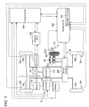
- FIG. 1 is a schematic block diagram of a vehicle incorporating a vehicle brake system in one embodiment according to the present invention
- FIG. 2 is a circuit diagram of a hydraulic brake device incorporated in the system shown in FIG. 1 ;
- FIG. 3 is a graph showing the correlation between motor rotational speed and drive pressure difference
- FIG. 4 is a flow chart of a control program executed by a brake ECU shown in FIG. 1 ;
- FIG. 5 is a flow chart of a subroutine constituting a part of the control program shown in FIG. 4 ;
- FIG. 6 is a time chart showing the relation between the composition of brake forces during a cooperative regenerative braking and the stroke of a brake pedal
- FIG. 7 is another time chart in an enlarged scale of a part of the time chart shown in FIG. 6 , particularly showing the detail of the relation between regenerative brake force, controlled hydraulic brake force and motor rotational speed;
- FIG. 8 is a simplified representation of the oil passages shown in FIG. 2 ;
- FIG. 9 is a time chart showing the relation between the composition of brake forces during a cooperative regenerative braking and the stroke of a brake pedal in the prior art.
- FIG. 1 is a schematic view showing the construction of the hybrid vehicle
- FIG. 2 is a schematic view showing the construction of a hydraulic brake device.
- the hybrid vehicle is a vehicle of the type that drives drive wheels such as, for example, left and right front wheels FL, FR by a hybrid system.
- the hybrid system is a power train which uses power sources of two kinds including an engine 11 and an electric motor 12 in combination.
- the system is a parallel hybrid system of the type that directly drives the wheels by both of the engine 11 and the motor 12 .
- Other types of the hybrid system include a serial hybrid system, wherein an electric motor serves to drive wheels while an engine serves as a supply source of electric power to the motor.
- the hybrid vehicle incorporating the parallel hybrid system is provided with the engine 11 and the electric motor 12 .
- the driving power of the engine 11 is transmitted to drive wheels (left and right front wheels FL, FR in the present embodiment) through a power divider mechanism 13 and a power transmission mechanism 14 .
- the driving power of the electric motor 12 is transmitted to the drive wheels through the power transmission mechanism 14 .
- the power divider mechanism 13 appropriately divides the driving power of the engine 11 into a vehicle driving power and a generator or dynamo driving power.
- the power transmission mechanism 14 appropriately combines the driving powers of the engine 11 and the electric motor 12 in dependence on the traveling condition to transmit the combined driving power to the drive wheels.
- the power transmission mechanism 14 is constructed to adjust the ratio between the driving powers transmitted from the engine 11 and the electric motor 12 in a range of 0:100 to 100:0.
- the power transmission mechanism 14 has a variable speed function.
- the electric motor 12 assists the output of the engine 11 to enhance the driving power on one hand and generates electricity to charge a battery 17 during the braking operation of the vehicle on the other hand.
- a generator or dynamo 15 generates electricity by being driven by the output of the engine 11 and functions as a starter at the time of engine start.
- the electric motor 12 and the dynamo 15 are electrically connected to an inverter 16 .
- the inverter 16 is electrically connected to the battery 17 as a direct-current power supply.
- the inverter 16 converts the alternate-current voltage inputted from the electric motor 12 and the dynamo 15 into direct-current voltage to supply the same to the battery 17 or conversely converts the direct-current voltage from the battery 17 into the alternate-current voltage to supply the same to the electric motor 12 and the dynamo 15 .
- the motor 12 , the inverter 16 and the battery 17 constitute a regenerative brake device A, which causes any of the respective wheel FL, FR, RL, RR (the left and right front wheels FL, FR driven by the electric motor 12 as a drive power source in the present invention) to generate a regenerative brake force in dependence on the brake operation state detected by brake operation state detection means.
- the brake operation state is the operation state of a brake pedal 21 and can be detected in the form of, e.g., either or the combination of a stroke amount of the brake pedal 21 , a stepping force on the brake pedal 21 , a master cylinder pressure correlating with the stepping force, and the like.
- the brake operation state detection means is for detecting the brake operation state and is constituted by a pedal stroke sensor 21 a for detecting the stroke amount of the brake pedal 21 , a pressure sensor P for detecting the master cylinder pressure, and the like.
- the engine 11 is controllable by an engine ECU (Electronic Control Unit) 18 , which regulates the rotational speed of the engine 11 by outputting an opening command to an electronic control throttle (not shown) in accordance with an engine output demand value from a hybrid ECU (Electronic Control Unit) 19 referred to later.
- ECU Electronic Control Unit
- the hybrid ECU 19 is connected to the inverter 16 to be able to communicate with each other.
- the hybrid ECU 19 derives a required engine power, an electric motor torque and a dynamo torque from the accelerator opening degree and the shift position (calculated from a shift position signal inputted from a shift position sensor (not shown)) and transmits a derived engine power demand value to the engine ECU 18 to control the driving power of the engine 11 .
- the hybrid ECU 19 controls the electric motor 12 and the dynamo 15 through the inverter 16 in accordance with a derived electric motor torque demand value and a derived dynamo torque demand value.
- the hybrid ECU 19 is connected to the battery 17 and monitors the charging state, charging current and the like of the battery 17 .
- the hybrid ECU 19 is also connected to an accelerator opening degree sensor (not shown) which is built in a gas or accelerator pedal (not shown) for detecting the accelerator opening degree of the vehicle, and inputs an accelerator opening degree signal from the accelerator opening degree sensor.
- the hybrid vehicle is provided with a hydraulic brake device B for applying hydraulic brake forces directly on the respective wheels FL, FR, RL, RR to brake the vehicle.
- the hydraulic brake device B is of the construction that a master cylinder 23 generates a base hydraulic pressure corresponding to the brake operation state made by the stepping of the brake pedal 21 , that the generated base hydraulic pressure is applied directly to wheel cylinders WC 1 -WC 4 of the respective wheels FL, FR, RL, RR which are connected to the master cylinder 23 through oil passages Lf, Lr respectively having hydraulic control valves 31 , 41 thereon, to make each wheel FL, FR, RL, RR generate a base hydraulic brake force corresponding to the base hydraulic pressure, and that controlled hydraulic pressures which are generated, independently of the base hydraulic pressure generated in dependence on the braking operation state, by driving the pump 37 , 47 and by controlling the hydraulic control valves 31 , 41 are applied to the wheel cylinder WC 1 -WC 4 of the respective wheels FL, FR,
- the hydraulic brake device B is composed of a vacuum booster 22 which is a booster device for assisting and boosting (enhancing) a brake operation force given by the stepping operation of the brake pedal 21 upon receiving the intake vacuum of the engine 11 on a diaphragm thereof, a master cylinder 23 for generating brake hydraulic (oil) pressure which is the base hydraulic pressure depending on the brake operation force (i.e., the operation state of the brake pedal 21 ) boosted by the vacuum booster 22 , to supply the brake hydraulic pressure to the wheel cylinders WC 1 -WC 4 , a reservoir tank 24 storing brake fluid for replenishing the same to the master cylinder 23 , and a brake actuator (controlled hydraulic brake force generating device) 25 provided between the master cylinder 23 and the wheel cylinders WC 1 -WC 4 for generating controlled hydraulic pressures.
- the brake pedal 21 , the vacuum booster 22 , the master cylinder 23 and the reservoir tank 24 constitute a base hydraulic brake force generating device.
- a brake piping system of the hydraulic brake device B in the present embodiment takes a piping form of front-rear separation, and first and second hydraulic chambers 23 d , 23 f of the master cylinder 23 are connected respectively to oil passages Lr and Lf, as shown in FIG. 2 .
- the oil passage Lr makes the first hydraulic chamber 23 d communicate with the wheel cylinders WC 3 , WC 4 of the left and right rear wheels RL, RR, while the oil passage Lf makes the second hydraulic chamber 23 f communicate with the wheel cylinders WC 1 , WC 2 of the left and right front wheels FL, FR.
- respective brake means BK 1 -BK 4 which are provided in correspondence respectively to the wheel cylinders WC 1 -WC 4 are operated to apply a hydraulic brake force (the sum of a base hydraulic brake force and a controlled hydraulic brake force) to each of the wheels FL, FR, RL, RR.
- a hydraulic brake force the sum of a base hydraulic brake force and a controlled hydraulic brake force
- each brake means BK 1 -BK 4 there is used a disc brake, a drum brake or the like, wherein friction members such as, e.g., brake pads, brake shoes or the like restrict the rotation of a disc rotor, a brake drum or the like provided bodily with each wheel.
- the brake actuator 25 is generally well-known in the art and is constructed by packaging within one case the hydraulic control valves 31 , 41 , pressure increasing control valves 32 , 33 , 42 , 43 and pressure reducing control valves 35 , 36 , 45 , 46 , pressure regulation reservoirs 34 , 44 , the pumps 37 , 47 , an electric motor M and the like.
- the pressure increasing control valves 32 , 33 , 42 , 43 and the pressure reducing control valves 35 , 36 , 45 , 46 operate as ABS control valves.
- the oil passage Lf is provided with the hydraulic control valve 31 constituted by a pressure difference control valve.
- the hydraulic control valve 31 is controllable by a brake ECU (Electronic Control Unit) 60 selectively to a communication state and a pressure difference state.
- the hydraulic control valve 31 is normally held in the communication state, but when brought into the pressure difference state, is able to hold the oil passage Lf 2 on the side of the wheel cylinders WC 1 , WC 2 to be higher in pressure by a predetermined controlled pressure difference than the oil passage Lf 1 on the side of the master cylinder 23 .
- the controlled pressure difference is regulatable in dependence on a control current from the brake ECU 60 .
- the hydraulic control valve 31 has a small-diameter valve hole (the same construction as a valve hole 32 a shown in FIG. 8 ).
- the valve hole of the hydraulic control valve 31 serves as a throttle hole, whereby a pressure difference (drive pressure difference) is generated between the master cylinder side and the wheel cylinder side of the hydraulic control valve 31 .
- the oil passage Lf 2 is branched to two branch passages Lf 2 , Lf 2 .
- One of the branch passages is provided with the pressure increasing control valve 32 for controlling the pressure increase of brake hydraulic pressure supplied to the wheel cylinder WC 1 in a pressure increase mode under the ABS control
- the other branch passage is provided with the pressure increasing control valve 33 for controlling the pressure increase of brake hydraulic pressure supplied to the wheel cylinder WC 2 in the pressure increase mode under the ABS control.
- Each of the pressure increasing control valves 32 , 33 is constituted as a two-position valve which is controllable by the brake ECU 60 to be brought selectively into either of the communication and blocked states.
- the pressure increasing control valves 32 , 33 are able to apply the base hydraulic pressure from the master cylinder 23 or/and a controlled hydraulic pressure generated by controlling the pump 37 and the hydraulic control valve 31 , to the respective wheel cylinders WC 1 , WC 2 . Further, the pressure increasing control valves 32 , 33 are able to perform the ABS control in cooperation with the pressure reducing control valves 35 , 36 and the pump 37 .
- the pressure increasing control valves 32 , 33 are controlled to be continually in the communication state.
- Safety valves 32 a , 33 a are provided in parallel relation respectively with the pressure increasing control valves 32 , 33 and operate to return brake fluids from the wheel cylinders WC 1 , WC 2 sides to the reservoir tank 24 when the brake pedal 21 is released under the ABS control.
- oil passages Lf 2 , Lf 2 between the pressure increasing control valves 32 , 33 and the respective wheel cylinders WC 1 , WC 2 communicate with a reservoir hole 34 a of the pressure regulation reservoir 34 through an oil passage Lf 3 branched to be connected to the oil passages Lf 2 , Lf 2 .
- Branched portions of the oil passage Lf 3 respectively have arranged thereon the pressure reducing control valves 35 , 36 each of which is controllable by the brake ECU 60 to be brought selectively into either of communication and blocked states.
- the pressure reducing control valves 35 , 36 are continually held in the blocked state at the time of the normal braking state (at the time of the ABS not operating), but when brought into the communication state timely or intermittently, serve to drain the brake fluids through the oil passage Lf 3 to the pressure regulation reservoir 34 , so that the brake hydraulic pressures in the wheel cylinders WC 1 , WC 2 are controlled to prevent the wheels from tending to lock.
- the pump 37 is arranged together with a safety valve 37 a on an oil passage Lf 4 which connects the oil passage Lf 2 between the hydraulic control valve 31 and the pressure increasing control valves 32 , 33 , to the reservoir hole 34 a of the pressure regulation reservoir 34 .
- an oil passage Lf 5 is provided to connect a reservoir hole 34 b of the pressure regulation reservoir 34 to the master cylinder 23 through the oil passage Lf 1 .
- the pump 37 is drivable by the electric motor M responsive to a command from the brake ECU 60 .
- the pump 37 draws brake fluids in the wheel cylinders WC 1 , WC 2 and the brake fluid stored in the pressure regulation reservoir 34 to return the drawn brake fluids to the master cylinder 23 through the hydraulic control valve 31 held in the communication state.
- the pump 37 draws the brake fluid within the master cylinder 23 through the oil passages Lf 1 , Lf 5 and the pressure regulation reservoir 34 and discharges the drawn brake fluid to the wheel cylinders WC 1 , WC 2 through the oil passages Lf 4 , Lf 2 , Lf 2 and the pressure increasing control valves 32 , 33 held in the communication state to apply a controlled hydraulic pressure to the wheel cylinders WC 1 , WC 2 so that the hydraulic control valve 31 having been switched to the pressure difference state generates the controlled hydraulic pressure.
- a damper 138 is arranged on the oil passage Lf 4 at an upstream side of the pump 37 .
- the oil passage Lf 1 is connected to the aforementioned pressure sensor P for detecting the master cylinder pressure which is the brake hydraulic pressure within the master cylinder 23 .
- the detection signal from the pressure sensor P is transmitted to the brake ECU 60 .
- the pressure sensor P may be connected to an oil passage Lr 1 for a rear-wheel hydraulic system.
- the master cylinder pressure represents one of the brake operation states.
- FIGS. 1 and 2 illustrate both of the pressure sensor P and the pedal stroke sensor 21 a .
- the pressure sensor P is incorporated.
- the pedal stroke sensor 21 a may be incorporated in another form or embodiment.
- the rear-wheel hydraulic system of the brake actuator 25 has the same construction as the front-wheel hydraulic system as described above, and the oil passage Lr constituting the rear-wheel hydraulic system is composed of oil passages Lr 1 -Lr 5 similarly to those of the oil passage Lf.
- the oil passage Lr is provided thereon with the aforementioned hydraulic control valve 41 similar to the hydraulic control valve 31 and a pressure regulation reservoir 44 similar to the pressure regulation reservoir 34 .
- Branched oil passages Lr 2 , Lr 2 communicating respectively with the wheel cylinders WC 3 , WC 4 are provided thereon with the aforementioned pressure increasing control valves 42 , 43 similar to the pressure increasing control valves 32 , 33 , and the oil passage Lr 3 is provided with the aforementioned pressure reducing control valves 45 , 46 similar to the pressure reducing control valves 35 , 36 at portions thereof branched to be connected to the oil passages Lr 2 , Lr 2 .
- the oil passage Lr 4 is provided thereon with the aforementioned pump 47 , a safety valve 47 a and a damper 48 similar to the pump 37 , the safety valve 37 a and the damper 138 .
- Safety valves 42 a , 43 a similar to the safety valves 32 a , 33 a are provided in parallel relation respectively to the pressure increasing control valves 42 , 43 .
- each wheel FL, FR, RL, RR generate a controlled hydraulic brake force by applying controlled hydraulic pressures, which are generated by driving the pumps 37 , 47 and by controlling the hydraulic control valves 31 , 41 , respectively to the wheel cylinders WC 1 -WC 4 of the wheels FL, FR, RL, RR.
- the vehicle brake system is provided with wheel speed sensors Sfl, Sfr, Srl, Srr.
- the wheel speed sensors Sfl, Sfr, Sri, Srr are provided in the neighborhoods of the wheels FL, FR, RL, RR and output to the brake ECU 60 pulse signals of the frequencies respectively corresponding to the rotational speeds of the wheels FL, FR, RL, RR.
- the brake ECU 60 is connected to the wheel speed sensors Sfl, Sfr, Srl, Srr, the pressure sensor P, the respective control valves 31 - 33 , 35 - 36 , 41 - 43 and 45 - 46 , and the electric motor M.
- the brake ECU 60 has a microcomputer (not shown) composed of an input/output interface, a CPU, a RAM and a ROM (all not shown) which are mutually connected through bus lines. By executing cooperative control programs shown in FIGS.
- the CPU controls the electric motor M of the hydraulic brake device B in response to detection signals from the aforementioned various sensors as well as to an actual regeneration execution value from the hybrid ECU 19 and also executes the switching control or the energization current control of the various control valves 31 - 33 , 35 - 36 , 41 - 43 and 45 - 46 , thereby to control the controlled hydraulic pressures applied to the wheel cylinders WC 1 -WC 4 , that is, the controlled hydraulic brake forces applied to the wheels FL, FR, RL, RR.
- the RAM temporally stores variables necessary for the execution of the programs, and the ROM stores the aforementioned cooperative control programs (vehicle brake control programs).
- the brake ECU 60 has beforehand stored in a storage device (storage means) 61 a map, a table or calculation expressions representing the relation between the brake operation state represented by the master cylinder pressure (or the stroke of the brake pedal 21 ) and a target total brake force which is to be applied to the wheels FL, FR, RL, RR in dependence on the brake operation state. Further, the storage device 61 has also beforehand stored therein a map, a table or calculation expressions representing the relation between the brake operation state represented by the master cylinder pressure and a base hydraulic brake force which is to be applied to the wheels FL, FR, RL, RR in dependence on the brake operation state.
- the storage device 61 has also beforehand stored therein a map, a table or calculation expressions representing the relation between the brake operation state represented by the master cylinder pressure and a target regenerative brake force which is to be applied to the wheels FL, FR, RL, RR in dependence on the brake operation state.
- the brake ECU 60 is connected to the hybrid ECU 19 to be able to communicate with each other and executes a cooperative control between the regenerative brake performed by the electric motor 12 and the hydraulic brake so that the total brake force given to the vehicle becomes equivalent to that given in a vehicle wherein the hydraulic brake only is performed. More specifically, the brake ECU 60 outputs to the hybrid ECU 19 a regenerative demand value, indicating a part of the total brake force which part should be undertaken by the regenerative brake upon a brake demand by the driver, that is, in dependence on a brake operation state, as a target demand value or a target regenerative brake force for the regenerative brake device.
- the hybrid ECU 19 derives an actual regeneration execution value which is to be actually applied as a regenerative brake, based on the regeneration demand value (target regenerative brake force) inputted thereto and taking the vehicle speed, the battery charging state and the liken into consideration and controls the electric motor 12 through the inverter 16 to generate a regenerative brake force corresponding to the actual regeneration execution value while outputting the derived actual regeneration execution value to the brake ECU 60 .
- the storage device 61 stores the map or calculation expressions represented in FIG. 3 .
- the map or the calculation expressions represent the relation between the rotational speed N (motor rotational speed) of the electric motor M of the hydraulic brake device B and a pressure difference ⁇ P.
- the pressure difference ⁇ P is defined as follows. As mentioned earlier with reference to FIG. 8 , when the pump 38 is driven by the operation of the electric motor 39 with a command being issued to the hydraulic control valve 32 to make the controlled pressure difference thereacross zero (i.e., in the case of the commanded controlled pressure difference being zero), the pressure on the wheel cylinder side of the hydraulic control valve 32 becomes higher than the pressure on the master cylinder side.
- the valve hole 32 a of the hydraulic control valve 32 serves as a throttle hole to generate a pressure difference between the master cylinder 25 side and the wheel cylinder 30 side of the hydraulic control valve 32 .
- This generated pressure difference is the aforementioned drive pressure difference. If the difference of the wheel cylinder side pressure from the master cylinder side pressure is less than the predetermined pressure, the valve hole 32 a of the hydraulic control valve 32 does not serve as a throttle hole, whereby no drive pressure difference is generated between the master cylinder 25 side and the wheel cylinder 30 side of the hydraulic control valve 32 .
- the aforementioned map is set so that the drive pressure difference ⁇ P becomes zero when the motor rotational speed N is lower than a predetermined rotational speed Na. Further, the map is set so that when the motor rotational speed N is equal to or higher than the predetermined rotational speed Na, the drive pressure difference ⁇ P increases as the motor rotational speed N increases.
- a maximum drive pressure difference ⁇ Pmax is set for a maximum rotational speed Nmax of the electric motor M.
- the predetermined rotational speed Na is defined to be a motor rotational speed N which does not cause the drive pressure difference to be generated. When the motor rotational speed N is less than the predetermined rotational speed Na, the wheel cylinder pressure (W/C pressure) remains same as the master cylinder pressure (M/C pressure).
- the wheel cylinder pressure (W/C pressure) becomes a pressure value which is made by adding the drive pressure difference ⁇ P to the master cylinder pressure (M/C pressure).
- the brake ECU 60 inputs the master cylinder pressure representing the brake operation state from the pressure sensor P at predetermined time intervals. Then, by reference to the map, the brake ECU 60 calculates a target total brake force Ftb*(n) and a target regenerative brake force Frb*(n) which correspond to the master cylinder pressure.
- the hydraulic brake device B applies a base hydraulic brake force corresponding to the master cylinder pressure, while the regenerative brake device A applies a regenerative brake force corresponding to the target regenerative brake force Frb*(n).
- a total brake force which is made by adding the regenerative brake force to the base hydraulic brake force, is applied to the wheels.
- a controlled hydraulic brake force is applied in combination with a base hydraulic brake force and a regenerative brake force.
- a target total brake force Ftb*(n) and a target regenerative brake force Frb*(n) which correspond to the master cylinder pressure are calculated by reference to the map having been stored in advance. Then, as described later in detail, a difference between the target regenerative brake force Frb*(n) and an actual regenerative brake force Frb_act(n) is calculated as a target controlled hydraulic brake force Fcfb*(n).
- the regenerative brake device A applies the actual regenerative brake force Frb_act(n) which the regenerative brake device A is able to apply actually when instructed to apply the target regenerative brake force Frb*(n), while the hydraulic brake device B applies the base hydraulic brake force corresponding to the master cylinder pressure and the target controlled hydraulic brake force Fcfb*(n) which corresponds to the difference between the target regenerative brake force Frb*(n) and the actual regenerative brake force Frb_act(n).
- the total brake force which is made by adding the controlled hydraulic brake force and the regenerative brake force to the base hydraulic brake force is applied to the wheels.
- the controlled hydraulic brake force control in the vehicle brake system as constructed above will be described in accordance with flow charts shown in FIGS. 4 and 5 .
- Description will be made by taking as an example the case that the total brake force is composed of a base hydraulic brake force and a regenerative brake force wherein because of an actual regenerative brake force being insufficient relative to a target regenerative brake force, a controlled hydraulic brake force is used to compensate for such an insufficient part of the regenerative brake force.
- the brake ECU 60 executes the programs corresponding to the aforementioned flow charts at the intervals of a predetermined short-time T.
- the brake ECU 60 inputs a master cylinder pressure representing the brake operation state from the pressure sensor P (step 102 ) and calculates a target regenerative brake force Frb*(n) corresponding to the inputted master cylinder pressure (step 104 ).
- the brake ECU 60 uses the map, table or calculation expressions stored in advance and representing the relation between the master cylinder pressure or the brake operation state and the target regenerative brake force to be applied to the wheels FL, FR, RL, RR.
- the brake ECU 60 When the target regenerative brake force Frb*(n) is greater than zero (YES at step 106 ), the brake ECU 60 outputs the target regenerative brake force Frb*(n) calculated at step 104 to the hybrid ECU 19 (step 108 ).
- the hybrid ECU 19 inputs a regenerative demand value indicative of the target regenerative brake force Frb*(n) and controls the electric motor 12 through the inverter 16 to make the electric motor 12 generate a regenerative brake force based on the regenerative demand value and with the vehicle speed and the battery charging state taken into consideration while outputting an actual regeneration execution value to the brake ECU 60 .
- the regenerative brake force only is add to the base hydraulic brake force to apply the sum to the wheels FL, FR, RL, RR.
- the brake ECU 60 compensates for the difference between the target regenerative brake force Frb*(n) and the regenerative brake force (actual regenerative brake force) Frb_act(n) which is being actually applied by the regenerative brake device A to any of the wheels FL, FR, RL, RR (steps 110 - 116 ).
- the brake ECU 60 inputs from the hybrid ECU 19 the actual regeneration execution value indicative of the actual regenerative brake force Frb_act(n) which the regenerative brake device A is actually applying to any of the wheels FL, FR, RL, RR when inputting the target regenerative brake force Frb*(n) calculated at step 104 (step 110 ).
- the brake ECU 60 calculates the difference between the target regenerative brake force Frb*(n) calculated at step 104 and the actual regenerative brake force Frb_act(n) inputted at step 110 (step 112 ).
- the brake ECU 60 detects the fluctuation in the regenerative brake force if the calculated difference is greater than a predetermined value (a) (step 114 ).
- the brake ECU 60 When detecting the fluctuation in the regenerative brake force, the brake ECU 60 makes a judgment of YES at step 114 and executes a controlled hydraulic brake force control at step 116 . Specifically, the brake ECU 60 executes a controlled hydraulic brake force control subroutine shown in FIG. 5 .
- the brake ECU 60 calculates a target controlled hydraulic brake force Fcfb*(n) as a controlled hydraulic pressure command value (step 202 ). That is, the brake ECU 60 sets the difference calculated at step 112 as the target controlled hydraulic brake force Fcfb*(n). Then, the brake ECU 60 calculates a gradient ⁇ Fcfb(n) of the target controlled hydraulic brake force Fcfb* based on a target controlled hydraulic brake force Fcfb*(n ⁇ 1) calculated in a preceding processing and the target controlled hydraulic brake force Fcfb*(n) calculated in the present processing (step 204 ). In a modified form, the gradient ⁇ Fcfb(n) may be calculated not only by using the values in the present processing and the preceding processing but also by using the values in a plural number of the past processing.
- the brake ECU 60 makes a judgment of YES at step 206 and sets the motor rotational speed to a smaller rotational speed than that corresponding to the target controlled hydraulic brake force Fcfb* (step 208 ).
- the brake ECU 60 alters the rotational speed to that smaller by a predetermined rotational speed ⁇ N.
- the rotational speed N 2 is decreased by the predetermined rotational speed ⁇ N to a rotational speed N 1 .
- the rotational speed N 1 is equal to or greater than a rotational speed corresponding to the discharge pressure of the pumps 37 , 47 which is necessary to generate the controlled hydraulic pressure.
- the brake ECU 60 alters the rotational speed to the predetermined rotational speed Na, as shown in FIG. 3 .
- N 2 which is higher than the predetermined rotational speed Na
- the brake ECU 60 alters the rotational speed to the predetermined rotational speed Na, as shown in FIG. 3 .
- the brake ECU 60 derives a motor rotational speed corresponding to the restricted quantity by the use of the map shown in FIG. 3 , so that the motor rotational speed can be decreased in dependence on the restricted quantity.
- the brake ECU 60 may make the motor rotational speed variable in dependence on the gradient of the target controlled hydraulic brake force Fcfb* to be given to the hydraulic brake device B.
- the brake ECU 60 uses a map, a table or calculation expressions which have been stored in advance to represent the relation between the motor rotational speed and the target controlled hydraulic brake force Fcfb*.
- the brake ECU 60 drives the electric motor M at the motor rotational speed so set to drive the pumps 37 , 47 and at the same time, applies an electric current to the hydraulic control valves 31 , 41 so that the hydraulic pressure of brake fluid supplied from the pumps 37 , 47 to the wheel cylinders WC 1 -WC 4 comes to correspond to the target controlled hydraulic brake force Fcfb* (step 212 ).
- the hydraulic brake device B applies a controlled hydraulic brake force component of the total brake force to the wheels FL, FR, RL, RR.
- the brake ECU 60 makes a judgment of NO at step 206 and sets the motor rotational speed to a rotational speed corresponding to the target controlled hydraulic brake force Fcfb* (step 210 ).
- the brake ECU 60 uses the map, table or calculation expressions which have been stored in advance to represent the relation between the motor rotational speed and the target controlled hydraulic brake force Fcfb*.
- the brake ECU 60 controls the pumps 37 , 47 and the hydraulic control valves 31 , 41 in the same manner as described above (step 212 ), whereby the hydraulic brake device B applies a controlled hydraulic brake force component of the total brake force to the wheels FL, FR, RL, RR.
- the brake ECU 60 Upon termination of the processing for the controlled hydraulic brake force control subroutine shown in FIG. 5 , the brake ECU 60 returns the program to that shown in FIG. 4 to terminate the program of FIG. 4 temporarily.
- the brake ECU 60 makes a judgment of NO at step 114 and discontinues the controlled hydraulic brake force control which has been executed in accordance with the aforementioned controlled hydraulic brake force control subroutine (step 118 ). Thereafter, the brake ECU 60 terminates the program shown in FIG. 4 temporarily.
- Controlling the controlled hydraulic brake force (step 116 ) upon detection of the fluctuation in the regenerative brake force at step 114 means, in other words, executing the controlled hydraulic brake force control for changing the rotational speed of the motor M when at least both of the regenerative brake force and the controlled hydraulic brake force are being applied.
- the driver begins to step the brake pedal 21 at a time point t 1 on the traveling of the vehicle.
- the brake pedal 21 is moved at a suitable stepping speed until a time point t 2 , and the stepping amount of the brake pedal 21 is held constant from the time point t 2 until a time point t 6 .
- a base hydraulic brake force (the right-ascending oblique line portion labeled “BHBF” in FIG. 6 ) and a regenerative brake force (the gray-masked portion labeled “RBF” in FIG. 6 ) are basically applied to the wheels FL, FR, RL, RR (cooperative regenerative brake).
- the controlled hydraulic brake force compensates for the difference.
- This compensation by the controlled hydraulic brake force is being performed within the period from the time point t 2 to the time point t 6 . That is, as shown in FIG. 7 in an enlarged scale, the compensation by the controlled hydraulic brake force is being performed for the period from a time point t 3 to a time point t 5 .
- the brake ECU 60 makes a judgment of NO at step 206 and sets the motor rotational speed to the rotational speed N 2 corresponding to the target controlled hydraulic brake force Fcfb* (step 210 ).
- the motor rotational speed N is set to the predetermined rotational speed Na.
- the judgment of YES is made at step 206 , and the motor rotational speed is set to a smaller rotational speed than that corresponding to the target controlled hydraulic brake force Fcfb* (step 208 ).
- the motor rotational speed N since the motor rotational speed N has already been set to the predetermined rotational speed Na, the same rotational speed Na is maintained if the pressure by driving the pumps 37 , 47 is necessary, but the rotational speed N is further decreased if not necessary.
- the pumps 37 , 47 are driven by the driving of the electric motor M at the constant rotational speed Na which suppresses the difference of the pressure on the wheel cylinder side from the pressure on the master cylinder side to be less than the predetermined pressure. Therefore, the generation of the drive pressure difference ⁇ P can be suppressed, whereby it results that the target controlled hydraulic brake force to which an additional force corresponding to the drive pressure difference ⁇ P is not added is applied to the wheels FL, FR, RL, RR.
- the brake ECU 60 makes a judgment of NO at step 114 and stops the controlled hydraulic brake force control which has been executed in accordance with the aforementioned controlled hydraulic brake force control subroutine (step 118 ).
- the brake ECU 60 initiates a brake force alteration control (i.e., a so-called “replacement control”) for gradually switching the regenerative brake force to the controlled hydraulic brake force.
- a brake force alteration control i.e., a so-called “replacement control”
- the brake ECU 60 terminates the brake force alteration control by stopping the application of the regenerative brake force.
- the base hydraulic brake force and the controlled hydraulic brake force are applied to the wheels FL, FR, RL, RR, whereby the vehicle is stopped finally (the time point t 8 ).
- the brake ECU 60 serving as controlled hydraulic brake force control means decreases the rotational speed of the electric motor M when at least both of the regenerative brake force and the controlled hydraulic brake force are being applied. Therefore, without adding a brake force component attributed to the drive pressure difference to a controlled hydraulic brake force set as target or by suppressing the added brake force component attributed to the drive pressure difference to be as small as possible, the controlled hydraulic brake force which is applied actually can be controlled to be a brake force set as target or to be a such a brake force as close as possible to that set as target.
- the regenerative brake force can be applied with a brake force which it should undertake in dependence on the operation state of the brake pedal 21 or with that which is as close as possible to such a brake force, the efficiency in utilizing the regenerative energy can be enhanced when at least both of the regenerative brake force and the controlled hydraulic brake force are applied.
- the brake ECU 60 serving as controlled hydraulic brake force control means decreases the rotational speed N of the electric motor M when the gradient of the target controlled hydraulic brake force being a controlled hydraulic pressure command value to the hydraulic brake device B is downhill or is not present.
- the gradient of the target controlled hydraulic brake force is uphill, it becomes possible to increase the supply pressures from the pumps 37 , 47 quickly without decreasing the motor rotational speed N and to supply the controlled hydraulic brake force as quickly as possible.
- the gradient of the controlled hydraulic pressure command value is downhill or is not present because of low in demand for the supply pressures from the pumps 37 , 47 , it is possible to decrease the motor rotational speed. Accordingly, the efficiency in utilizing the regenerative energy can be enhanced timely without harming the quick supply of the controlled hydraulic brake force.
- the hydraulic control valves 31 , 41 are electromagnetic valves which are switchable selectively to the pressure difference state that a controlled pressure difference is generated between the master cylinder side and the wheel cylinder side and the direct communication state that no controlled pressure difference is generated therebetween, and when a command is issued for making the hydraulic control valves 31 , 41 generate the controlled pressure difference of zero, the brake ECU 60 serving as controlled hydraulic brake force control means decreases the rotational speed N of the electric motor M by reference to the map representing the relation between the rotational speed N of the electric motor M and the drive pressure difference ⁇ P which the hydraulic pressure generated by driving the pumps 37 , 47 causes to be generated between the master cylinder side and the wheel cylinder side of each hydraulic control valve 31 , 41 .
- the brake ECU 60 serving as controlled hydraulic brake force control means decreases the rotational speed N of the electric motor M by reference to the map representing the relation between the rotational speed N of the electric motor M and the drive pressure difference ⁇ P which the hydraulic pressure generated by driving the pumps 37 , 47 causes to be generated between the master cylinder side
- the hydraulic control valves 31 , 41 are electromagnetic valves which are switchable selectively to the pressure difference state that a controlled pressure difference is generated between the master cylinder side and the wheel cylinder side and the direct communication state that no controlled pressure difference is generated therebetween, and when a command is issued for making the hydraulic control valves 31 , 41 generate the controlled pressure difference of zero, the brake ECU 60 serving as controlled hydraulic brake force control means decreases the rotational speed of the electric motor M so that the hydraulic pressure generated by driving each of the pumps 37 , 47 does not cause the drive pressure difference ⁇ P to be generated between the master cylinder side and the wheel cylinder side of each hydraulic control valve 31 , 41 .
- the controlled hydraulic brake force which is actually applied can be controlled to a brake force set as target without adding any brake force attributed to the drive pressure difference ⁇ P to the controlled hydraulic brake force set as target. Accordingly, since the regenerative brake force can be applied with a brake force which it should undertake in dependence on the operation state of the brake pedal 21 , the efficiency in utilizing the regenerative energy can be enhanced when at least both of the regenerative brake force and the controlled hydraulic brake force are applied.
- the brake ECU 60 serving as controlled hydraulic brake force control means makes the rotational speed N of the electric motor M variable in correspondence to the gradient of the target controlled hydraulic brake force being the controlled hydraulic pressure command value to the hydraulic brake device B.
- the brake ECU 60 serving as controlled hydraulic brake force control means makes the rotational speed N of the electric motor M variable in correspondence to the gradient of the target controlled hydraulic brake force being the controlled hydraulic pressure command value to the hydraulic brake device B.
- the piping in the front-rear separation form is arranged in a front-engine front-drive vehicle.
- the piping in the front-rear separation form may be arranged in a front-engine rear-drive vehicle.
- the vacuum booster is used as a booster device.
Landscapes
- Engineering & Computer Science (AREA)
- Mechanical Engineering (AREA)
- Transportation (AREA)
- Power Engineering (AREA)
- Chemical & Material Sciences (AREA)
- Combustion & Propulsion (AREA)
- Life Sciences & Earth Sciences (AREA)
- Sustainable Development (AREA)
- Sustainable Energy (AREA)
- Automation & Control Theory (AREA)
- Physics & Mathematics (AREA)
- Electromagnetism (AREA)
- Regulating Braking Force (AREA)
- Electric Propulsion And Braking For Vehicles (AREA)
Abstract
Description
Claims (3)
Applications Claiming Priority (2)
| Application Number | Priority Date | Filing Date | Title |
|---|---|---|---|
| JP2006-110477 | 2006-04-13 | ||
| JP2006110477A JP4830600B2 (en) | 2006-04-13 | 2006-04-13 | Braking device for vehicle |
Publications (2)
| Publication Number | Publication Date |
|---|---|
| US20070284936A1 US20070284936A1 (en) | 2007-12-13 |
| US8042886B2 true US8042886B2 (en) | 2011-10-25 |
Family
ID=38514751
Family Applications (1)
| Application Number | Title | Priority Date | Filing Date |
|---|---|---|---|
| US11/689,029 Expired - Fee Related US8042886B2 (en) | 2006-04-13 | 2007-03-21 | Vehicle brake system |
Country Status (3)
| Country | Link |
|---|---|
| US (1) | US8042886B2 (en) |
| JP (1) | JP4830600B2 (en) |
| DE (1) | DE102007000180A1 (en) |
Cited By (5)
| Publication number | Priority date | Publication date | Assignee | Title |
|---|---|---|---|---|
| US20080228367A1 (en) * | 2007-03-15 | 2008-09-18 | Honda Motor Co., Ltd. | Vehicle regeneration cooperative braking system |
| CN102765378A (en) * | 2012-07-12 | 2012-11-07 | 清华大学 | Braking energy recycling device of electric automobile and method for controlling braking energy recycling device |
| US20130193747A1 (en) * | 2012-01-30 | 2013-08-01 | Advics Co., Ltd. | Brake control device for vehicle |
| US20140183933A1 (en) * | 2012-12-27 | 2014-07-03 | Robert Bosch Gmbh | Method of decelerating a vehicle with regenerative and friction braking |
| US20160178020A1 (en) * | 2013-09-09 | 2016-06-23 | Ntn Corporation | Electric brake device |
Families Citing this family (14)
| Publication number | Priority date | Publication date | Assignee | Title |
|---|---|---|---|---|
| US8112194B2 (en) * | 2007-10-29 | 2012-02-07 | GM Global Technology Operations LLC | Method and apparatus for monitoring regenerative operation in a hybrid powertrain system |
| JP5374934B2 (en) * | 2008-06-20 | 2013-12-25 | トヨタ自動車株式会社 | Travel control device |
| DE102009005937A1 (en) * | 2009-01-23 | 2010-07-29 | Continental Teves Ag & Co. Ohg | Electrohydraulic braking system and method of operation |
| FR2974343B1 (en) * | 2011-04-20 | 2013-04-12 | Renault Sa | DEVICE FOR SECURING A BRAKE CONTROL DISTRIBUTION DEVICE. |
| JP5866817B2 (en) * | 2011-06-24 | 2016-02-24 | 株式会社アドヴィックス | Brake device for vehicle |
| JP5708295B2 (en) * | 2011-06-24 | 2015-04-30 | 株式会社アドヴィックス | Brake device for vehicle |
| DE102011084746B4 (en) | 2011-10-19 | 2021-02-11 | Ford Global Technologies, Llc | Control method for a hydraulic brake system of a motor vehicle and a brake system |
| JP5797542B2 (en) * | 2011-12-20 | 2015-10-21 | 日立オートモティブシステムズ株式会社 | Brake device |
| DE102012023345B4 (en) * | 2012-11-29 | 2021-03-04 | Zf Active Safety Gmbh | Brake system for a land vehicle and method for controlling the brake system |
| JP5895916B2 (en) * | 2013-09-26 | 2016-03-30 | 株式会社アドヴィックス | Brake control device for vehicle |
| JP5856133B2 (en) * | 2013-12-11 | 2016-02-09 | 本田技研工業株式会社 | Vehicle braking system |
| WO2017110010A1 (en) * | 2015-12-21 | 2017-06-29 | パナソニックIpマネジメント株式会社 | Speed control device for electric vehicle |
| JP6939286B2 (en) * | 2017-09-06 | 2021-09-22 | 株式会社アドヴィックス | Vehicle braking device |
| CN110979017A (en) * | 2019-11-25 | 2020-04-10 | 江铃汽车股份有限公司 | NBS-based braking energy recovery system and method for electric automobile |
Citations (10)
| Publication number | Priority date | Publication date | Assignee | Title |
|---|---|---|---|---|
| US5927829A (en) * | 1995-10-03 | 1999-07-27 | Mitsubishi Jidosha Kogyo Kabushiki Kaisha | Brake apparatus for electric automobile utilizing regenerative braking |
| DE19909809A1 (en) | 1998-03-19 | 1999-09-30 | Toyota Motor Co Ltd | Brake energy control device for motor vehicles |
| JP2001071880A (en) | 1999-09-07 | 2001-03-21 | Denso Corp | Vehicle braking device and vehicle braking method |
| US20020014379A1 (en) * | 2000-04-21 | 2002-02-07 | Bosch Braking Systems Co., Ltd & Denso Corporation | Brake apparatus |
| JP2002255018A (en) | 2001-02-28 | 2002-09-11 | Bosch Braking Systems Co Ltd | Brake system |
| US6494547B2 (en) * | 2000-06-26 | 2002-12-17 | Sunitomo (Sei) Brake Systems, Inc. | Brake system for electric motor-powered vehicle |
| JP2003306137A (en) | 2002-04-11 | 2003-10-28 | Denso Corp | Brake control device |
| US6957874B2 (en) * | 2001-05-30 | 2005-10-25 | Toyota Jidosha Kabushiki Kaisha | Braking force control apparatus for a vehicle |
| US20050269875A1 (en) | 2004-06-08 | 2005-12-08 | Kazuya Maki | Vehicle brake device |
| JP2006021745A (en) | 2004-06-11 | 2006-01-26 | Advics:Kk | Brake device for vehicle and brake control program for vehicle |
-
2006
- 2006-04-13 JP JP2006110477A patent/JP4830600B2/en active Active
-
2007
- 2007-03-21 US US11/689,029 patent/US8042886B2/en not_active Expired - Fee Related
- 2007-03-27 DE DE102007000180A patent/DE102007000180A1/en not_active Withdrawn
Patent Citations (12)
| Publication number | Priority date | Publication date | Assignee | Title |
|---|---|---|---|---|
| US5927829A (en) * | 1995-10-03 | 1999-07-27 | Mitsubishi Jidosha Kogyo Kabushiki Kaisha | Brake apparatus for electric automobile utilizing regenerative braking |
| DE19909809A1 (en) | 1998-03-19 | 1999-09-30 | Toyota Motor Co Ltd | Brake energy control device for motor vehicles |
| US6120115A (en) | 1998-03-19 | 2000-09-19 | Toyota Jidosha Kabushiki Kaisha | Vehicle braking energy control apparatus and method |
| JP2001071880A (en) | 1999-09-07 | 2001-03-21 | Denso Corp | Vehicle braking device and vehicle braking method |
| US20020014379A1 (en) * | 2000-04-21 | 2002-02-07 | Bosch Braking Systems Co., Ltd & Denso Corporation | Brake apparatus |
| US6494547B2 (en) * | 2000-06-26 | 2002-12-17 | Sunitomo (Sei) Brake Systems, Inc. | Brake system for electric motor-powered vehicle |
| JP2002255018A (en) | 2001-02-28 | 2002-09-11 | Bosch Braking Systems Co Ltd | Brake system |
| US6957874B2 (en) * | 2001-05-30 | 2005-10-25 | Toyota Jidosha Kabushiki Kaisha | Braking force control apparatus for a vehicle |
| JP2003306137A (en) | 2002-04-11 | 2003-10-28 | Denso Corp | Brake control device |
| US20050269875A1 (en) | 2004-06-08 | 2005-12-08 | Kazuya Maki | Vehicle brake device |
| DE102005024339A1 (en) | 2004-06-08 | 2006-01-19 | Advics Co., Ltd., Kariya | Vehicle brake device |
| JP2006021745A (en) | 2004-06-11 | 2006-01-26 | Advics:Kk | Brake device for vehicle and brake control program for vehicle |
Non-Patent Citations (2)
| Title |
|---|
| Office Action issued Mar. 30, 2010 by the German Patent Office in corresponding German Patent Application No. 10 2007 000 180.2-21, and English-language translation of Office Action. |
| Office Action issued Nov. 2, 2010 by the Japanese Patent Office in Japanese Patent Application No. 2006-110477, and English language translation of Official Action. |
Cited By (9)
| Publication number | Priority date | Publication date | Assignee | Title |
|---|---|---|---|---|
| US20080228367A1 (en) * | 2007-03-15 | 2008-09-18 | Honda Motor Co., Ltd. | Vehicle regeneration cooperative braking system |
| US8781701B2 (en) * | 2007-03-15 | 2014-07-15 | Honda Motor Co., Ltd. | Vehicle regeneration cooperative braking system |
| US20130193747A1 (en) * | 2012-01-30 | 2013-08-01 | Advics Co., Ltd. | Brake control device for vehicle |
| US8998351B2 (en) * | 2012-01-30 | 2015-04-07 | Advics Co., Ltd. | Brake control device for vehicle |
| CN102765378A (en) * | 2012-07-12 | 2012-11-07 | 清华大学 | Braking energy recycling device of electric automobile and method for controlling braking energy recycling device |
| CN102765378B (en) * | 2012-07-12 | 2014-07-30 | 清华大学 | Braking energy recycling device of electric automobile and method for controlling braking energy recycling device |
| US20140183933A1 (en) * | 2012-12-27 | 2014-07-03 | Robert Bosch Gmbh | Method of decelerating a vehicle with regenerative and friction braking |
| US20160178020A1 (en) * | 2013-09-09 | 2016-06-23 | Ntn Corporation | Electric brake device |
| US9709112B2 (en) * | 2013-09-09 | 2017-07-18 | Ntn Corporation | Electric brake device |
Also Published As
| Publication number | Publication date |
|---|---|
| JP2007283811A (en) | 2007-11-01 |
| US20070284936A1 (en) | 2007-12-13 |
| JP4830600B2 (en) | 2011-12-07 |
| DE102007000180A1 (en) | 2007-10-18 |
Similar Documents
| Publication | Publication Date | Title |
|---|---|---|
| US8042886B2 (en) | Vehicle brake system | |
| US7284803B2 (en) | Vehicle brake control apparatus | |
| US8777336B2 (en) | Brake apparatus for vehicle | |
| JP5351256B2 (en) | Brake device for automobile, operation method thereof and hydraulic device | |
| US8469463B2 (en) | Brake control apparatus and method for controlling the brake | |
| US5882093A (en) | Brake control system for an electrically operated vehicle | |
| US9296376B2 (en) | Vehicle brake system | |
| US8727455B2 (en) | Brake control apparatus | |
| US20050269875A1 (en) | Vehicle brake device | |
| US6244674B1 (en) | Brake control system for an electrically operated vehicle | |
| US20120161505A1 (en) | Brake control apparatus | |
| US7275795B2 (en) | Braking system of hybrid vehicle | |
| US20070267915A1 (en) | Vehicle and control method of vehicle | |
| US20060125317A1 (en) | Vehicle-brake control unit | |
| US9233668B2 (en) | Vehicle braking control device | |
| US20100089709A1 (en) | Vehicle brake control apparatus | |
| JP2014051285A (en) | Brake device of automobile, hydraulic device therefor, and operation method of brake device | |
| JP4719061B2 (en) | Vehicle and control method thereof | |
| JP2007276655A (en) | Vehicular brake control device | |
| JP4355164B2 (en) | Vehicle braking device | |
| JP4779768B2 (en) | Vehicle braking device | |
| JP5521657B2 (en) | Brake control device | |
| CN111065559B (en) | Vehicle brake device | |
| JPH1191565A (en) | Braking control system for motor vehicle | |
| CN115402286A (en) | Brake control device for hybrid vehicle |
Legal Events
| Date | Code | Title | Description |
|---|---|---|---|
| AS | Assignment |
Owner name: ADVICS CO., INC., JAPAN Free format text: ASSIGNMENT OF ASSIGNORS INTEREST;ASSIGNORS:MAKI, KAZUYA;KOKUBO, KOICHI;NAITO, MASAYUKI;REEL/FRAME:020267/0673 Effective date: 20070312 |
|
| ZAAA | Notice of allowance and fees due |
Free format text: ORIGINAL CODE: NOA |
|
| ZAAB | Notice of allowance mailed |
Free format text: ORIGINAL CODE: MN/=. |
|
| STCF | Information on status: patent grant |
Free format text: PATENTED CASE |
|
| FPAY | Fee payment |
Year of fee payment: 4 |
|
| MAFP | Maintenance fee payment |
Free format text: PAYMENT OF MAINTENANCE FEE, 8TH YEAR, LARGE ENTITY (ORIGINAL EVENT CODE: M1552); ENTITY STATUS OF PATENT OWNER: LARGE ENTITY Year of fee payment: 8 |
|
| FEPP | Fee payment procedure |
Free format text: MAINTENANCE FEE REMINDER MAILED (ORIGINAL EVENT CODE: REM.); ENTITY STATUS OF PATENT OWNER: LARGE ENTITY |
|
| LAPS | Lapse for failure to pay maintenance fees |
Free format text: PATENT EXPIRED FOR FAILURE TO PAY MAINTENANCE FEES (ORIGINAL EVENT CODE: EXP.); ENTITY STATUS OF PATENT OWNER: LARGE ENTITY |
|
| STCH | Information on status: patent discontinuation |
Free format text: PATENT EXPIRED DUE TO NONPAYMENT OF MAINTENANCE FEES UNDER 37 CFR 1.362 |
|
| FP | Lapsed due to failure to pay maintenance fee |
Effective date: 20231025 |