US8042402B2 - Modular sensor assembly - Google Patents
Modular sensor assembly Download PDFInfo
- Publication number
- US8042402B2 US8042402B2 US12/113,614 US11361408A US8042402B2 US 8042402 B2 US8042402 B2 US 8042402B2 US 11361408 A US11361408 A US 11361408A US 8042402 B2 US8042402 B2 US 8042402B2
- Authority
- US
- United States
- Prior art keywords
- module
- sensing module
- base module
- assembly
- slip ring
- Prior art date
- Legal status (The legal status is an assumption and is not a legal conclusion. Google has not performed a legal analysis and makes no representation as to the accuracy of the status listed.)
- Active, expires
Links
Images


Classifications
-
- G—PHYSICS
- G01—MEASURING; TESTING
- G01D—MEASURING NOT SPECIALLY ADAPTED FOR A SPECIFIC VARIABLE; ARRANGEMENTS FOR MEASURING TWO OR MORE VARIABLES NOT COVERED IN A SINGLE OTHER SUBCLASS; TARIFF METERING APPARATUS; MEASURING OR TESTING NOT OTHERWISE PROVIDED FOR
- G01D11/00—Component parts of measuring arrangements not specially adapted for a specific variable
- G01D11/24—Housings ; Casings for instruments
- G01D11/245—Housings for sensors
-
- G—PHYSICS
- G01—MEASURING; TESTING
- G01D—MEASURING NOT SPECIALLY ADAPTED FOR A SPECIFIC VARIABLE; ARRANGEMENTS FOR MEASURING TWO OR MORE VARIABLES NOT COVERED IN A SINGLE OTHER SUBCLASS; TARIFF METERING APPARATUS; MEASURING OR TESTING NOT OTHERWISE PROVIDED FOR
- G01D11/00—Component parts of measuring arrangements not specially adapted for a specific variable
- G01D11/30—Supports specially adapted for an instrument; Supports specially adapted for a set of instruments
-
- G—PHYSICS
- G01—MEASURING; TESTING
- G01L—MEASURING FORCE, STRESS, TORQUE, WORK, MECHANICAL POWER, MECHANICAL EFFICIENCY, OR FLUID PRESSURE
- G01L19/00—Details of, or accessories for, apparatus for measuring steady or quasi-steady pressure of a fluent medium insofar as such details or accessories are not special to particular types of pressure gauges
- G01L19/0007—Fluidic connecting means
- G01L19/0015—Fluidic connecting means using switching means
-
- G—PHYSICS
- G01—MEASURING; TESTING
- G01L—MEASURING FORCE, STRESS, TORQUE, WORK, MECHANICAL POWER, MECHANICAL EFFICIENCY, OR FLUID PRESSURE
- G01L19/00—Details of, or accessories for, apparatus for measuring steady or quasi-steady pressure of a fluent medium insofar as such details or accessories are not special to particular types of pressure gauges
- G01L19/0007—Fluidic connecting means
- G01L19/0038—Fluidic connecting means being part of the housing
-
- G—PHYSICS
- G01—MEASURING; TESTING
- G01L—MEASURING FORCE, STRESS, TORQUE, WORK, MECHANICAL POWER, MECHANICAL EFFICIENCY, OR FLUID PRESSURE
- G01L19/00—Details of, or accessories for, apparatus for measuring steady or quasi-steady pressure of a fluent medium insofar as such details or accessories are not special to particular types of pressure gauges
- G01L19/0061—Electrical connection means
- G01L19/0084—Electrical connection means to the outside of the housing
-
- G—PHYSICS
- G01—MEASURING; TESTING
- G01L—MEASURING FORCE, STRESS, TORQUE, WORK, MECHANICAL POWER, MECHANICAL EFFICIENCY, OR FLUID PRESSURE
- G01L19/00—Details of, or accessories for, apparatus for measuring steady or quasi-steady pressure of a fluent medium insofar as such details or accessories are not special to particular types of pressure gauges
- G01L19/14—Housings
- G01L19/142—Multiple part housings
- G01L19/144—Multiple part housings with dismountable parts, e.g. for maintenance purposes or for ensuring sterile conditions
Definitions
- the present invention relates generally to modular sensor assemblies, and more particularly to mechanical and electrical connection of a detachable sensing module to a base module.
- Sensors of pressure, temperature, current, etc. are used in a wide range of industrial and consumer applications, including measurement and calibration of components and instruments. Flexibility to use one measurement or calibration system for various measurement or calibration tasks can be achieved by providing detachable sensing modules which can be used with the same base module. Depending upon a particular application, the measurement or calibration system should be able to operate under harsh environmental, vibration, impact, and other operating conditions. The connection between the sensing module and the base module should be able to withstand high pressure for applications involving pressure measurement or calibration.
- a modular sensor assembly for performing measurement or calibration comprising a sensing module comprising a threaded spigot, a first slip ring conductive track, and a second slip ring conductive track; a base module comprising a threaded receptacle, a first conductor, and a second conductor; wherein the sensing module is detachably mounted to the base module by rotating the threaded spigot into the threaded receptacle thereby forming a first electrical connection between the first slip ring conductive track and the first conductor, and a second electrical connection between the second slip ring conductive track and the second conductor.
- FIG. 1 illustrates an exploded view of one embodiment of an interface between a sensing module and a base module of a measurement or calibration device.
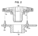
- FIG. 2 illustrates a cross-section view of one embodiment of an interface between a sensing module and a base module of a measurement or calibration device.
- FIG. 3 illustrates one embodiment of a base module of a measurement or calibration device adapted to receive two sensing modules.
- FIG. 4 illustrates a cross section view of one embodiment of an interface between a sensing module and a base module of a measurement or calibration device.
- FIG. 5 illustrates an electrical diagram of one embodiment of a sample implementation of the physical layer of a data interface between a sensing module and a base module of a measurement or calibration device.
- FIG. 1 shows an exploded view
- FIG. 2 shows a cross-section of one embodiment of the interface of a sensing module and a base module.
- the sensing module 100 can be provided, depending upon the application requirements, e.g., by a pressure sensor, a voltage sensor, a temperature sensor, a humidity sensor, a flow sensor, a pressure calibrating module, a voltage calibrating module, a current calibrating module, etc.
- a pressure sensor e.g., a pressure sensor, a voltage sensor, a temperature sensor, a humidity sensor, a flow sensor, a pressure calibrating module, a voltage calibrating module, a current calibrating module, etc.
- a skilled artisan would appreciate the fact that the present invention can be practiced with alternative types and configurations of sensing modules, and hence the description set forth herein is not intended to restrict or limit the practice of the present invention to any particular type of a sensing module.
- the sensing module 100 can be externally mountable to a base module 202 , as best viewed in FIG. 3 .
- FIG. 3 illustrates a base module 202 which is adapted to receive two sensing modules 100 and 101 .
- the base module 202 can be adapted to receive one or more sensing modules 100 .
- components of the sensing module 100 can, in one aspect, be incorporated in a housing 102 .
- the sensing module 100 can have substantially cylindrical form factor.
- the sensing module 100 can include a threaded spigot 104 .
- the threaded spigot 104 can provide a mechanical attachment of the sensing module 100 to the interface part 120 of the base module 202 .
- the threaded spigot 104 can be threadably attached to the base module receptacle 122 having an internal threaded part.
- the sensing module 100 can be driven into engagement with the base module 202 by an operator placing the spigot 104 into the base module receptacle 122 and rotating the sensing module 100 relative to the base module 202 .
- the threaded interface can provide for establishing reliable mechanical connection of the sensing module 100 to the base module 202 using only hand movement force of the operator.
- the diameter 106 of the spigot 104 can be the only controlled dimension of the interface between the sensing module 100 and the base module 202 , thus allowing the sensing module 100 to be shaped in numerous form factors and in continuum of dimensions to satisfy alternative application needs, as well as be adapted to facilitate a secure grip of the sensing module 100 by the operator's hand.
- the spigot 104 can be hollow, i.e., can have an opening 132 which, together with the opening 134 in the base module receptacle 122 , can allow gas or liquid to move freely between the inside volumes of the sensing module 100 and the base module 202 , which can be necessary for certain applications, e.g., pneumatic or hydraulic pressure measurement or calibration.
- the mechanical connection between the sensing module 100 and the base module 202 can be sealed to withstand high pressure values, which can be necessary, e.g., for applications involving pneumatic or hydraulic pressure measurement or calibration.
- the mechanical connection between the sensing module 100 and the base module 202 can withstand pressure values up to 1000 bar.
- the environmental sealing of the connection can be provided by one or more O-rings 302 , 303 , as best viewed in FIG. 4 .
- both the sensing module 100 and the base module 202 can remain sealed when disconnected from each other.
- FIG. 4 illustrates the base module interface part 120 being equipped with the isolation valve 304 which is in a normally closed state supported by a loaded spring 306 when no sensing module 100 is connected to the base module 202 , thus shuttering the opening to the base module 202 .
- the isolation valve 304 can be pushed to an open state by the spigot 104 when the sensing module 100 is rotatably tightened and connected to the base module 202 .
- the isolation valve 304 returns to its normally closed state, preventing the ejection of gas or liquid from the base module 202 .
- a skilled artisan would appreciate the fact that other designs of the isolation valve 304 are within the spirit and the scope of the present invention.
- the sensing module 100 can comprise one or more slip ring conductive tracks 110 , 111 providing electrical coupling between the components of the sensing module 100 and the base module 202 .
- the slip ring conductive track 110 provides power transmission between the base module 202 and the sensing module 100 .
- the slip ring conductive track 111 provides data transmission between the base module 202 and the sensing module 100 .
- the slip ring conductive tracks 110 , 111 can be provided by precious metal plating embedded into a non-conductive material (e.g., plastic).
- a pair of conductors in the form of spring loaded pins 310 , 311 can be mounted on the interface part 120 of the base module 202 and can be adapted to make electrical contact with the respective slip ring conductive tracks 110 , 111 when the sensing module 100 and the base module 202 are connected together.
- the pins 310 , 311 can be made of a conductive material and be electrically coupled to the data transmission and power transmission circuitries of the base module 202 .
- the spigot 104 and base module receptacle 122 can be made of a conductive material, and adapted to carry electrical ground connection between the sensing module 100 and the base module 202 .
- bi-directional data transmission between the sensing module 100 and the base module 102 can be performed via a single data wire including a slip ring conductive track 111 in contact with a spring loaded pin 311 as described herein.
- the single-wire interface can provide half-duplex serial data transmission and operate according to the following sample specifications: 1 start bit, 8 data bits, 1 stop bit, odd parity, 115 Kbaud.
- the electrical diagram of a sample implementation of the physical layer of the data interface is shown in FIG. 5 .
- a universal asynchronous receiver/transmitter (UART) 402 on the sensing module 100 side can communicate with a UART 403 on the base module 202 side over a single data line 404 via two non-inverting open collector drivers 406 and 407 buffering the output of the respective transmission ports 408 , 409 of the two UARTs.
- the data line 404 can be pulled high by a pull-up resistor 410 when a transmission port is driven high.
- the respective receiving ports 412 , 413 of the two UARTs can be coupled to the data line 404 , thus providing half-duplex serial data communication via a single data line 404 .
- the power line 420 can be provided by a second conductive slip ring track 110 in contact with a spring loaded pin 310 as described herein, and the ground line 430 can be provided by the conductive spigot 104 in contact with the base module receptacle 122 , as described herein.
- a specific hardware and software protocols can be employed to facilitate the data exchange over the data transmission line provided by the slip ring conductive track 111 and one or more brushes or pins.
Landscapes
- Physics & Mathematics (AREA)
- General Physics & Mathematics (AREA)
- Measuring Fluid Pressure (AREA)
- Arrangements For Transmission Of Measured Signals (AREA)
Abstract
Description
Claims (13)
Priority Applications (7)
| Application Number | Priority Date | Filing Date | Title |
|---|---|---|---|
| US12/113,614 US8042402B2 (en) | 2008-05-01 | 2008-05-01 | Modular sensor assembly |
| JP2011507522A JP5453395B2 (en) | 2008-05-01 | 2009-04-07 | Modular sensor assembly |
| KR1020107024439A KR101180233B1 (en) | 2008-05-01 | 2009-04-07 | Modular sensor assembly |
| CN2009801165530A CN102016515A (en) | 2008-05-01 | 2009-04-07 | Modular sensor assembly |
| EP09739395.3A EP2274581B1 (en) | 2008-05-01 | 2009-04-07 | Modular sensor assembly |
| PCT/US2009/039713 WO2009134593A1 (en) | 2008-05-01 | 2009-04-07 | Modular sensor assembly |
| CN201510498856.0A CN105157738B (en) | 2008-05-01 | 2009-04-07 | Modular sensor assembly |
Applications Claiming Priority (1)
| Application Number | Priority Date | Filing Date | Title |
|---|---|---|---|
| US12/113,614 US8042402B2 (en) | 2008-05-01 | 2008-05-01 | Modular sensor assembly |
Publications (2)
| Publication Number | Publication Date |
|---|---|
| US20090272205A1 US20090272205A1 (en) | 2009-11-05 |
| US8042402B2 true US8042402B2 (en) | 2011-10-25 |
Family
ID=41055286
Family Applications (1)
| Application Number | Title | Priority Date | Filing Date |
|---|---|---|---|
| US12/113,614 Active 2030-07-26 US8042402B2 (en) | 2008-05-01 | 2008-05-01 | Modular sensor assembly |
Country Status (6)
| Country | Link |
|---|---|
| US (1) | US8042402B2 (en) |
| EP (1) | EP2274581B1 (en) |
| JP (1) | JP5453395B2 (en) |
| KR (1) | KR101180233B1 (en) |
| CN (2) | CN105157738B (en) |
| WO (1) | WO2009134593A1 (en) |
Cited By (24)
| Publication number | Priority date | Publication date | Assignee | Title |
|---|---|---|---|---|
| US20110174901A1 (en) * | 2008-10-29 | 2011-07-21 | Peter Dettlaff | Gravity cup for a paint sprayer |
| US20120012671A1 (en) * | 2009-05-07 | 2012-01-19 | Sata Gmbh Co. Kg | Spray gun with pressure measuring device |
| US20140116145A1 (en) * | 2012-10-26 | 2014-05-01 | Acellent Technologies, Inc. | System and method for monitoring the structural health of rotating elements |
| USD740393S1 (en) | 2013-09-27 | 2015-10-06 | Sata Gmbh & Co. Kg | Paint spray gun |
| US9327301B2 (en) | 2008-03-12 | 2016-05-03 | Jeffrey D. Fox | Disposable spray gun cartridge |
| USD758537S1 (en) | 2014-07-31 | 2016-06-07 | Sata Gmbh & Co. Kg | Paint spray gun rear portion |
| US9409197B2 (en) | 2013-12-18 | 2016-08-09 | Sata Gmbh & Co. Kg | Air nozzle closure for a spray gun |
| USD768820S1 (en) | 2014-09-03 | 2016-10-11 | Sata Gmbh & Co. Kg | Paint spray gun with pattern |
| USD770593S1 (en) | 2014-07-31 | 2016-11-01 | Sata Gmbh & Co. Kg | Paint spray gun |
| US20160370212A1 (en) * | 2015-06-17 | 2016-12-22 | Berkeley Springs Instruments Llc | Transducer mounting apparatus |
| US9533317B2 (en) | 2009-07-08 | 2017-01-03 | Sata Gmbh & Co. Kg | Paint spray gun |
| US9782784B2 (en) | 2010-05-28 | 2017-10-10 | Sata Gmbh & Co. Kg | Nozzle head for a spray device |
| US9782785B2 (en) | 2010-12-02 | 2017-10-10 | Sata Gmbh & Co. Kg | Spray gun and accessories |
| US9878336B2 (en) | 2006-12-05 | 2018-01-30 | Sata Gmbh & Co. Kg | Fluid reservoir for a paint spray gun |
| US10189037B2 (en) | 2011-06-30 | 2019-01-29 | Sata Gmbh & Co. Kg | Easy-to-clean spray gun, accessories therefor, and mounting and dismounting methods |
| US10247313B2 (en) * | 2017-06-29 | 2019-04-02 | Tao-Pao Chien | Spray gun and adjustment valve thereof |
| US10464076B2 (en) | 2015-12-21 | 2019-11-05 | Sata Gmbh & Co. Kg | Air cap and nozzle assembly for a spray gun, and spray gun |
| US10471449B2 (en) | 2016-08-19 | 2019-11-12 | Sata Gmbh & Co. Kg | Air cap arrangement and spray gun |
| US10702879B2 (en) | 2014-07-31 | 2020-07-07 | Sata Gmbh & Co. Kg | Spray gun manufacturing method, spray gun, spray gun body and cover |
| US10835911B2 (en) | 2016-08-19 | 2020-11-17 | Sata Gmbh & Co. Kg | Trigger for a spray gun and spray gun having same |
| US11141747B2 (en) | 2015-05-22 | 2021-10-12 | Sata Gmbh & Co. Kg | Nozzle arrangement for a spray gun |
| US11801521B2 (en) | 2018-08-01 | 2023-10-31 | Sata Gmbh & Co. Kg | Main body for a spray gun, spray guns, spray gun set, method for producing a main body for a spray gun and method for converting a spray gun |
| US11826771B2 (en) | 2018-08-01 | 2023-11-28 | Sata Gmbh & Co. Kg | Set of nozzles for a spray gun, spray gun system, method for embodying a nozzle module, method for selecting a nozzle module from a set of nozzles for a paint job, selection system and computer program product |
| US11865558B2 (en) | 2018-08-01 | 2024-01-09 | Sata Gmbh & Co. Kg | Nozzle for a spray gun, nozzle set for a spray gun, spray guns and methods for producing a nozzle for a spray gun |
Families Citing this family (15)
| Publication number | Priority date | Publication date | Assignee | Title |
|---|---|---|---|---|
| DE102008001865A1 (en) * | 2008-05-19 | 2009-11-26 | Endress + Hauser Gmbh + Co. Kg | gauge |
| CN102441213B (en) * | 2010-10-09 | 2015-08-19 | 深圳迈瑞生物医疗电子股份有限公司 | Oxygen cell holder assembly, oxygen cell assembly and anesthetic machine |
| US9709461B2 (en) * | 2012-11-30 | 2017-07-18 | Sensata Technologies, Inc. | Method of integrating a temperature sensing element |
| US9329061B2 (en) * | 2013-02-28 | 2016-05-03 | Rosemount Inc. | Reduced-stress coupling for industrial process transmitter housing |
| EP2806259B1 (en) * | 2013-05-24 | 2019-08-14 | Ansaldo Energia Switzerland AG | Sensor mounting attachment |
| EP2827113A1 (en) * | 2013-07-18 | 2015-01-21 | Itron GmbH | Gas meter with a fire safety device |
| CN103644928B (en) * | 2013-11-27 | 2016-09-14 | 芜湖致通汽车电子有限公司 | A kind of sensor attachment structure |
| DE102014215504A1 (en) * | 2014-08-06 | 2016-02-11 | Robert Bosch Gmbh | Sensor module with at least one interface |
| EP3308124B1 (en) * | 2015-06-09 | 2021-06-02 | Moog GmbH | Pressure sensor module with electrical contacts |
| FR3040214B1 (en) * | 2015-08-18 | 2017-09-15 | Continental Automotive France | MEASURING SENSOR WITH ELECTRIC COMPONENT SUPPORT FOR A MOTOR VEHICLE |
| US10405069B2 (en) * | 2016-06-19 | 2019-09-03 | Urban-Gro, Inc. | Modular sensor architecture for soil and water analysis at various depths from the surface |
| US10955402B2 (en) * | 2016-06-19 | 2021-03-23 | Urban-Gro, Inc. | Modular sensor architecture for soil and water analysis at various depths from the surface |
| US20210268501A1 (en) * | 2018-06-20 | 2021-09-02 | Aeromon Oy | Analyser, an analyser body and a sensor part |
| CN112203707B (en) * | 2018-08-17 | 2023-12-12 | 深圳迈瑞生物医疗电子股份有限公司 | Ventilation equipment |
| CN114310743A (en) * | 2021-12-23 | 2022-04-12 | 天津福莱迪通讯设备有限公司 | Adjustable fixture for assembling electronic communication equipment based on sensor |
Citations (5)
| Publication number | Priority date | Publication date | Assignee | Title |
|---|---|---|---|---|
| US4667790A (en) * | 1984-07-12 | 1987-05-26 | Gewerkschaft Eisenhutte Westfalia | Gearing units |
| US5025914A (en) * | 1988-08-31 | 1991-06-25 | Okuma Machinery Works, Ltd. | Feed-screw support structure |
| US20060131489A1 (en) | 2004-12-17 | 2006-06-22 | Dr. Johannes Heidenhain Gmbh | Angle-measuring arrangement |
| DE102004049873B3 (en) | 2004-10-13 | 2006-08-31 | Robert Bosch Gmbh | Housing for e.g. peripheral acceleration sensor in motor vehicle, has two parts and electrical supply line arranged at one part, where parts are joined together to create electrical connection between electrical component and supply line |
| US20070279173A1 (en) | 2006-04-27 | 2007-12-06 | Abb Patent Gmbh | Measurement transmitter |
Family Cites Families (3)
| Publication number | Priority date | Publication date | Assignee | Title |
|---|---|---|---|---|
| CN2280899Y (en) * | 1996-08-15 | 1998-05-06 | 黄德珠 | Pressure sensor with automatic gas-complementing and gas-discharging device |
| WO2005037053A2 (en) * | 2003-05-23 | 2005-04-28 | Board Of Regents - The University Of Texas System | High throughput screening of aptamer libraries for specific binding to proteins on viruses and other pathogens |
| CN2758709Y (en) * | 2004-12-29 | 2006-02-15 | 石家庄科达仪器仪表有限公司 | Fluid self-closed type sensor device |
-
2008
- 2008-05-01 US US12/113,614 patent/US8042402B2/en active Active
-
2009
- 2009-04-07 KR KR1020107024439A patent/KR101180233B1/en active IP Right Grant
- 2009-04-07 EP EP09739395.3A patent/EP2274581B1/en active Active
- 2009-04-07 JP JP2011507522A patent/JP5453395B2/en active Active
- 2009-04-07 CN CN201510498856.0A patent/CN105157738B/en active Active
- 2009-04-07 CN CN2009801165530A patent/CN102016515A/en active Pending
- 2009-04-07 WO PCT/US2009/039713 patent/WO2009134593A1/en active Application Filing
Patent Citations (5)
| Publication number | Priority date | Publication date | Assignee | Title |
|---|---|---|---|---|
| US4667790A (en) * | 1984-07-12 | 1987-05-26 | Gewerkschaft Eisenhutte Westfalia | Gearing units |
| US5025914A (en) * | 1988-08-31 | 1991-06-25 | Okuma Machinery Works, Ltd. | Feed-screw support structure |
| DE102004049873B3 (en) | 2004-10-13 | 2006-08-31 | Robert Bosch Gmbh | Housing for e.g. peripheral acceleration sensor in motor vehicle, has two parts and electrical supply line arranged at one part, where parts are joined together to create electrical connection between electrical component and supply line |
| US20060131489A1 (en) | 2004-12-17 | 2006-06-22 | Dr. Johannes Heidenhain Gmbh | Angle-measuring arrangement |
| US20070279173A1 (en) | 2006-04-27 | 2007-12-06 | Abb Patent Gmbh | Measurement transmitter |
Non-Patent Citations (1)
| Title |
|---|
| PCT Search Report issued in connection with corresponding WO Patent Application No. PCT/US2009/039713 filed on Apr. 7, 2009. |
Cited By (30)
| Publication number | Priority date | Publication date | Assignee | Title |
|---|---|---|---|---|
| US9878336B2 (en) | 2006-12-05 | 2018-01-30 | Sata Gmbh & Co. Kg | Fluid reservoir for a paint spray gun |
| US9327301B2 (en) | 2008-03-12 | 2016-05-03 | Jeffrey D. Fox | Disposable spray gun cartridge |
| US8925836B2 (en) | 2008-10-29 | 2015-01-06 | Sata Gmbh & Co. Kg | Gravity cup for a paint sprayer |
| US20110174901A1 (en) * | 2008-10-29 | 2011-07-21 | Peter Dettlaff | Gravity cup for a paint sprayer |
| US8857732B2 (en) * | 2009-05-07 | 2014-10-14 | Sata Gmbh & Co Kg | Spray gun with pressure measuring device |
| US20120012671A1 (en) * | 2009-05-07 | 2012-01-19 | Sata Gmbh Co. Kg | Spray gun with pressure measuring device |
| US9533317B2 (en) | 2009-07-08 | 2017-01-03 | Sata Gmbh & Co. Kg | Paint spray gun |
| US9782784B2 (en) | 2010-05-28 | 2017-10-10 | Sata Gmbh & Co. Kg | Nozzle head for a spray device |
| US9782785B2 (en) | 2010-12-02 | 2017-10-10 | Sata Gmbh & Co. Kg | Spray gun and accessories |
| US10189037B2 (en) | 2011-06-30 | 2019-01-29 | Sata Gmbh & Co. Kg | Easy-to-clean spray gun, accessories therefor, and mounting and dismounting methods |
| US20140116145A1 (en) * | 2012-10-26 | 2014-05-01 | Acellent Technologies, Inc. | System and method for monitoring the structural health of rotating elements |
| US9791418B2 (en) * | 2012-10-26 | 2017-10-17 | Acellent Technologies, Inc. | System and method for monitoring the structural health of rotating elements |
| USD740393S1 (en) | 2013-09-27 | 2015-10-06 | Sata Gmbh & Co. Kg | Paint spray gun |
| US9409197B2 (en) | 2013-12-18 | 2016-08-09 | Sata Gmbh & Co. Kg | Air nozzle closure for a spray gun |
| USD758537S1 (en) | 2014-07-31 | 2016-06-07 | Sata Gmbh & Co. Kg | Paint spray gun rear portion |
| US10702879B2 (en) | 2014-07-31 | 2020-07-07 | Sata Gmbh & Co. Kg | Spray gun manufacturing method, spray gun, spray gun body and cover |
| USD770593S1 (en) | 2014-07-31 | 2016-11-01 | Sata Gmbh & Co. Kg | Paint spray gun |
| USD835235S1 (en) | 2014-07-31 | 2018-12-04 | Sata Gmbh & Co. Kg | Paint spray gun |
| USD798419S1 (en) | 2014-07-31 | 2017-09-26 | Sata Gmbh & Co. Kg | Paint spray gun |
| USD768820S1 (en) | 2014-09-03 | 2016-10-11 | Sata Gmbh & Co. Kg | Paint spray gun with pattern |
| US11141747B2 (en) | 2015-05-22 | 2021-10-12 | Sata Gmbh & Co. Kg | Nozzle arrangement for a spray gun |
| US10782161B2 (en) * | 2015-06-17 | 2020-09-22 | Berkeley Springs Instruments, Llc | Ultrasonic transducer mounting apparatus for attaching a transducer block to a pipeline |
| US20160370212A1 (en) * | 2015-06-17 | 2016-12-22 | Berkeley Springs Instruments Llc | Transducer mounting apparatus |
| US10464076B2 (en) | 2015-12-21 | 2019-11-05 | Sata Gmbh & Co. Kg | Air cap and nozzle assembly for a spray gun, and spray gun |
| US10471449B2 (en) | 2016-08-19 | 2019-11-12 | Sata Gmbh & Co. Kg | Air cap arrangement and spray gun |
| US10835911B2 (en) | 2016-08-19 | 2020-11-17 | Sata Gmbh & Co. Kg | Trigger for a spray gun and spray gun having same |
| US10247313B2 (en) * | 2017-06-29 | 2019-04-02 | Tao-Pao Chien | Spray gun and adjustment valve thereof |
| US11801521B2 (en) | 2018-08-01 | 2023-10-31 | Sata Gmbh & Co. Kg | Main body for a spray gun, spray guns, spray gun set, method for producing a main body for a spray gun and method for converting a spray gun |
| US11826771B2 (en) | 2018-08-01 | 2023-11-28 | Sata Gmbh & Co. Kg | Set of nozzles for a spray gun, spray gun system, method for embodying a nozzle module, method for selecting a nozzle module from a set of nozzles for a paint job, selection system and computer program product |
| US11865558B2 (en) | 2018-08-01 | 2024-01-09 | Sata Gmbh & Co. Kg | Nozzle for a spray gun, nozzle set for a spray gun, spray guns and methods for producing a nozzle for a spray gun |
Also Published As
| Publication number | Publication date |
|---|---|
| WO2009134593A1 (en) | 2009-11-05 |
| EP2274581B1 (en) | 2017-10-18 |
| CN105157738A (en) | 2015-12-16 |
| US20090272205A1 (en) | 2009-11-05 |
| CN105157738B (en) | 2020-01-07 |
| JP2011520103A (en) | 2011-07-14 |
| KR101180233B1 (en) | 2012-09-05 |
| KR20110009120A (en) | 2011-01-27 |
| EP2274581A1 (en) | 2011-01-19 |
| JP5453395B2 (en) | 2014-03-26 |
| CN102016515A (en) | 2011-04-13 |
Similar Documents
| Publication | Publication Date | Title |
|---|---|---|
| US8042402B2 (en) | Modular sensor assembly | |
| EP2542866B1 (en) | Process variable transmitter with display | |
| JP4612986B2 (en) | Process transmitter | |
| US7830314B2 (en) | Adjustable industrial antenna mount | |
| JP6568115B2 (en) | Intrinsically safe in-line adapter with built-in capacitive barrier for connecting wireless modules and antennas | |
| WO2007011275A8 (en) | Dielectric connector, dc-insulating through-connection and electronic system | |
| US20080110267A1 (en) | Fluid pressure sensing method and apparatus | |
| CN101863200B (en) | Signal transmitting device with air tap tire gauge | |
| WO2007080393A3 (en) | Apparatus for sensing parameters | |
| US20130162268A1 (en) | Measurement Transmitter with at least one Inductive Interface | |
| WO2011097445A4 (en) | Spoolable signal conduction and connection line and method | |
| CN104981128A (en) | Electronic unit of a fluid sensor or valve and fluid senor or fluid unit | |
| DE102008037194A1 (en) | Field device e.g. sensor, for use in process automation technology to detect and influence e.g. process variable, has housing extension including input element e.g. keyboard, for operating field device | |
| US10847926B2 (en) | Housing lid for a field device of automation technology for wireless transmission of information | |
| CN105241513A (en) | Wireless integrated temperature and pressure transmitter | |
| CN209799606U (en) | Vehicle lock for vehicle and vehicle | |
| CN205138550U (en) | Wireless integrated temperature and pressure transmitter | |
| AU2014201786A1 (en) | Remote telemetry units |
Legal Events
| Date | Code | Title | Description |
|---|---|---|---|
| AS | Assignment |
Owner name: GENERAL ELECTRIC COMPANY, NEW YORK Free format text: ASSIGNMENT OF ASSIGNORS INTEREST;ASSIGNORS:BROWN, RODERICK GORDON;MANKIA, HARBHAJAN SINGH;FLEMING, KEITH STUART;REEL/FRAME:020916/0035;SIGNING DATES FROM 20080423 TO 20080428 Owner name: GENERAL ELECTRIC COMPANY, NEW YORK Free format text: ASSIGNMENT OF ASSIGNORS INTEREST;ASSIGNORS:BROWN, RODERICK GORDON;MANKIA, HARBHAJAN SINGH;FLEMING, KEITH STUART;SIGNING DATES FROM 20080423 TO 20080428;REEL/FRAME:020916/0035 |
|
| STCF | Information on status: patent grant |
Free format text: PATENTED CASE |
|
| FPAY | Fee payment |
Year of fee payment: 4 |
|
| MAFP | Maintenance fee payment |
Free format text: PAYMENT OF MAINTENANCE FEE, 8TH YEAR, LARGE ENTITY (ORIGINAL EVENT CODE: M1552); ENTITY STATUS OF PATENT OWNER: LARGE ENTITY Year of fee payment: 8 |
|
| AS | Assignment |
Owner name: BAKER HUGHES, A GE COMPANY, LLC, TEXAS Free format text: ASSIGNMENT OF ASSIGNORS INTEREST;ASSIGNOR:GENERAL ELECTRIC COMPANY;REEL/FRAME:051624/0123 Effective date: 20170703 |
|
| AS | Assignment |
Owner name: BAKER HUGHES HOLDINGS LLC, TEXAS Free format text: CHANGE OF NAME;ASSIGNOR:BAKER HUGHES, A GE COMPANY, LLC;REEL/FRAME:062684/0256 Effective date: 20200413 |
|
| MAFP | Maintenance fee payment |
Free format text: PAYMENT OF MAINTENANCE FEE, 12TH YEAR, LARGE ENTITY (ORIGINAL EVENT CODE: M1553); ENTITY STATUS OF PATENT OWNER: LARGE ENTITY Year of fee payment: 12 |