US8042314B2 - Construction for buildings protected against radiation - Google Patents
Construction for buildings protected against radiation Download PDFInfo
- Publication number
- US8042314B2 US8042314B2 US12/639,646 US63964609A US8042314B2 US 8042314 B2 US8042314 B2 US 8042314B2 US 63964609 A US63964609 A US 63964609A US 8042314 B2 US8042314 B2 US 8042314B2
- Authority
- US
- United States
- Prior art keywords
- concrete
- layer
- gypsum
- wall
- double
- Prior art date
- Legal status (The legal status is an assumption and is not a legal conclusion. Google has not performed a legal analysis and makes no representation as to the accuracy of the status listed.)
- Expired - Fee Related
Links
- 230000005855 radiation Effects 0.000 title claims abstract description 39
- 238000010276 construction Methods 0.000 title claims abstract description 32
- 239000004567 concrete Substances 0.000 claims abstract description 71
- 239000000463 material Substances 0.000 claims abstract description 42
- 229910052602 gypsum Inorganic materials 0.000 claims description 48
- 239000010440 gypsum Substances 0.000 claims description 48
- 230000003471 anti-radiation Effects 0.000 claims description 35
- 238000000034 method Methods 0.000 claims description 15
- 239000000654 additive Substances 0.000 claims description 9
- XLYOFNOQVPJJNP-UHFFFAOYSA-N water Substances O XLYOFNOQVPJJNP-UHFFFAOYSA-N 0.000 claims description 7
- 239000002245 particle Substances 0.000 claims description 4
- WNROFYMDJYEPJX-UHFFFAOYSA-K aluminium hydroxide Chemical compound [OH-].[OH-].[OH-].[Al+3] WNROFYMDJYEPJX-UHFFFAOYSA-K 0.000 claims description 3
- 229910001679 gibbsite Inorganic materials 0.000 claims description 2
- 230000000996 additive effect Effects 0.000 claims 2
- OSGAYBCDTDRGGQ-UHFFFAOYSA-L calcium sulfate Chemical compound [Ca+2].[O-]S([O-])(=O)=O OSGAYBCDTDRGGQ-UHFFFAOYSA-L 0.000 claims 2
- FYYHWMGAXLPEAU-UHFFFAOYSA-N Magnesium Chemical compound [Mg] FYYHWMGAXLPEAU-UHFFFAOYSA-N 0.000 claims 1
- 229910052749 magnesium Inorganic materials 0.000 claims 1
- 239000011777 magnesium Substances 0.000 claims 1
- 239000011150 reinforced concrete Substances 0.000 abstract description 3
- XEEYBQQBJWHFJM-UHFFFAOYSA-N Iron Chemical compound [Fe] XEEYBQQBJWHFJM-UHFFFAOYSA-N 0.000 description 12
- 229910052742 iron Inorganic materials 0.000 description 6
- 239000002689 soil Substances 0.000 description 6
- 230000003068 static effect Effects 0.000 description 5
- CSNNHWWHGAXBCP-UHFFFAOYSA-L Magnesium sulfate Chemical compound [Mg+2].[O-][S+2]([O-])([O-])[O-] CSNNHWWHGAXBCP-UHFFFAOYSA-L 0.000 description 4
- 239000008187 granular material Substances 0.000 description 4
- 229910000831 Steel Inorganic materials 0.000 description 3
- 239000003673 groundwater Substances 0.000 description 3
- 239000010959 steel Substances 0.000 description 3
- PASHVRUKOFIRIK-UHFFFAOYSA-L calcium sulfate dihydrate Chemical compound O.O.[Ca+2].[O-]S([O-])(=O)=O PASHVRUKOFIRIK-UHFFFAOYSA-L 0.000 description 2
- 230000007797 corrosion Effects 0.000 description 2
- 238000005260 corrosion Methods 0.000 description 2
- 229910052943 magnesium sulfate Inorganic materials 0.000 description 2
- 235000019341 magnesium sulphate Nutrition 0.000 description 2
- 238000012216 screening Methods 0.000 description 2
- ZHZFKLKREFECML-UHFFFAOYSA-L calcium;sulfate;hydrate Chemical compound O.[Ca+2].[O-]S([O-])(=O)=O ZHZFKLKREFECML-UHFFFAOYSA-L 0.000 description 1
- 239000003814 drug Substances 0.000 description 1
- 230000000694 effects Effects 0.000 description 1
- 239000000945 filler Substances 0.000 description 1
- 229910052595 hematite Inorganic materials 0.000 description 1
- 239000011019 hematite Substances 0.000 description 1
- LIKBJVNGSGBSGK-UHFFFAOYSA-N iron(3+);oxygen(2-) Chemical compound [O-2].[O-2].[O-2].[Fe+3].[Fe+3] LIKBJVNGSGBSGK-UHFFFAOYSA-N 0.000 description 1
- 230000002045 lasting effect Effects 0.000 description 1
- 239000011133 lead Substances 0.000 description 1
- 238000004519 manufacturing process Methods 0.000 description 1
- 229910052751 metal Inorganic materials 0.000 description 1
- 239000002184 metal Substances 0.000 description 1
- 238000012986 modification Methods 0.000 description 1
- 230000004048 modification Effects 0.000 description 1
- 230000001681 protective effect Effects 0.000 description 1
- 230000002787 reinforcement Effects 0.000 description 1
- 239000007787 solid Substances 0.000 description 1
- 239000011343 solid material Substances 0.000 description 1
- 239000010935 stainless steel Substances 0.000 description 1
Images


Classifications
-
- G—PHYSICS
- G21—NUCLEAR PHYSICS; NUCLEAR ENGINEERING
- G21F—PROTECTION AGAINST X-RADIATION, GAMMA RADIATION, CORPUSCULAR RADIATION OR PARTICLE BOMBARDMENT; TREATING RADIOACTIVELY CONTAMINATED MATERIAL; DECONTAMINATION ARRANGEMENTS THEREFOR
- G21F1/00—Shielding characterised by the composition of the materials
- G21F1/12—Laminated shielding materials
-
- G—PHYSICS
- G21—NUCLEAR PHYSICS; NUCLEAR ENGINEERING
- G21F—PROTECTION AGAINST X-RADIATION, GAMMA RADIATION, CORPUSCULAR RADIATION OR PARTICLE BOMBARDMENT; TREATING RADIOACTIVELY CONTAMINATED MATERIAL; DECONTAMINATION ARRANGEMENTS THEREFOR
- G21F3/00—Shielding characterised by its physical form, e.g. granules, or shape of the material
Definitions
- the invention relates to a construction with walls, ceilings, and/or floors as parts of the building, especially for buildings protected against radiation in which the parts of the building are made of reinforced concrete.
- dismantling is necessary since the proton treatment equipment has a limited service life and is usually leased because it is so expensive.
- the time at which the devices are dismantled and hence (in certain circumstances) the building is dismantled can be predicted.
- An object of the present invention is therefore to create an economical construction, especially for radiation rooms, that meets the high demands of radiation screening and that may be dismantled economically if necessary. Additional objects and advantages of the invention will be set forth in part in the following description, or may be obvious from the description, or may be learned through practice of the invention.
- the part of the building of the construction is manufactured in a sandwich design.
- the building part has one layer of a material that protects against radiation and at least one layer of concrete.
- the concrete layer primarily serves as a type of shell for holding the antiradiation material.
- the concrete layer can also help screen against radiation,
- the material that protects against radiation is on the side of the concrete layer facing away from the radiation room.
- Water especially bound water, has proven to be a particularly effective material to protect against radiation.
- the water is bound to a solid material, and usually at least the same anti-radiation effect arises as with unbound water.
- the anti-radiation material is natural, unfired calcium sulfate dihydrate.
- Calcium sulfate dihydrate is natural gypsum, and is particularly suitable as an anti-radiation material because it binds water particularly well.
- An easy and fast mode of assembly is to slide into a cavity anti-radiation material made of gypsum panels that can be free-standing or mortared in. This type of construction is particularly advantageous for large, straight walls.
- the antiradiation material is pourable hardened granular gypsum.
- Gypsum in this form is easy to manufacture, transport and process.
- the particle size of the gypsum granules is 40 mm and below, the granules can be easily and compactly poured into the provided cavities. Such a particle size can be economically manufactured.
- the antiradiation material is advantageously compressed. This prevents undesirable cavities from arising in unfavorable circumstances that could impair the protection from radiation.
- the layer thickness of the anti-radiation material is selected as a function of the radiation intensity to be screened, different radiation protection can be achieved with the same material.
- additives consisting of gibbsite, hydragillite, aluminum hydrate or magnesium sulfate are added to the anti-radiation material. This can increase the protective effect.
- the antiradiation material When the antiradiation material is poured between a construction pit structure, in particular a sheet piling wall, and the concrete layer is poured in and possibly compressed, it achieves effective radiation protection for the environment, such as the groundwater.
- the antiradiation material is between two layers of concrete.
- the antiradiation material can be easily and quickly set up, which makes building the construction faster and more economical.
- prefabricated concrete parts can be used for particularly fast and economical construction.
- the use of prefabricated concrete parts is particularly advantageous and an inventive embodiment of the invention.
- the building part consists of two spaced double walls, and if the space between the two double walls is filled with antiradiation material, it is particularly economical to construct the radiation protection wall with a sandwich design.
- the double walls serve as permanent framework for the site-poured concrete that fills the gap between the two walls.
- the two double walls also serve as a permanent framework for the actual antiradiation material.
- the double walls are connected with tie rods running perpendicular to their lengthwise extension, the double walls are prevented from bulging when the antiradiation material is poured in, and the static strength of the double walls and concrete layer is increased.
- the double wall is advantageously made of prefabricated concrete panels with essentially parallel, spaced walls.
- the individual walls are connected in particular with wall lattice girders. Such double walls are relatively easy to make and transport.
- connecting elements for two double wall elements and/or one double wall element and a ceiling element are welded or screwed together, it produces a stable shell for pouring concrete into the cavity between the wall elements to yield a uniform, seamless concrete layer.
- the wall lattice girders between the wall elements are corrosion-resistant or are made of high-grade steel, impermissible corrosion and static weakness to the concrete layer are prevented.
- the construction is advantageously built of anti-radiation material. This protects the groundwater from radiation.
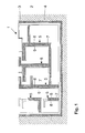
- FIG. 1 shows a plan of construction according to the invention
- FIG. 2 shows a cross-section of a construction according to the invention
- FIG. 3 shows a cross-section of a sandwich construction according to the invention with double concrete walls.
- the plan in FIG. 1 shows a construction ( 1 ) manufactured according to the invention.
- the construction ( 1 ) is surrounded by soil ( 2 ) on three sides.
- An outer wall ( 3 ) of the construction ( 1 ) is at a distance from the soil ( 2 ).
- a gypsum shell ( 4 ) is between the outer wall ( 3 ) and the soil ( 2 ).
- the gypsum shell ( 4 ) is the anti-radiation layer and provides the basic radiation protection of the construction ( 1 ) to the outside.
- the gypsum material used for the gypsum shell ( 4 ) consists of natural, unfired calcium sulfate hydrate, and is poured in the form of hardened, granulated gypsum between the outer wall ( 3 ) and the soil ( 2 ); or a sheet pile wall installed during construction that retains the soil ( 2 ).
- the sheet pile wall is removed after the gypsum material is poured into the gap, and compressed if applicable.
- the gypsum shell ( 4 ) is given a specific thickness, resulting from the specific distance between the sheet pile wall and the outer wall ( 3 ) to provide a specific radiation protection for the environment.
- the construction ( 1 ) in which radiation is generated is therefore screened from the environment to prevent damage to the environment.
- the outer wall ( 3 ) preferably consists of a concrete layer of heavy concrete that can contain iron additives to additionally provide radiation protection for the environment.
- Another type of sandwich design is provided for the inner walls ( 5 ) of the construction ( 1 ).
- Two concrete layers ( 6 ) are provided at a distance from each other.
- Antiradiation material preferably in the form of gypsum, is poured between the concrete layers ( 6 ).
- gypsum panels can be installed instead of the granules. This can provide additional stability and in certain circumstances improve radiation protection. In some designs, the gypsum panels can be installed more quickly and economically.
- the gypsum has a large amount of bound water and is therefore highly suitable as antiradiation material.
- the thickness of the gypsum or antiradiation layer can be selected as a function of the desired radiation protection. A thicker gypsum layer provides greater protection of neighboring rooms, and a thinner gypsum layer is sufficient when less screening is desired.
- Additives such as hydragillite, aluminum hydrate or magnesium sulfate can be added to the gypsum ( 7 ) to improve radiation protection. However, this is only necessary if extremely high radiation protection is required.
- the concrete layer ( 6 ) can either be made of site-mixed concrete that can be heavy concrete with iron additives, or it can consist of the double walls as shown in FIG. 3 .
- FIG. 2 shows a section of a construction ( 1 ) according to the intention.
- the construction ( 1 ) is buried in the earth ( 2 ).
- the gypsum shell ( 4 ) also surrounds the building, protecting it from the earth ( 2 ), and prevents the radiation generated in the construction ( 1 ) from entering the earth ( 2 ). This reliably prevents groundwater from being irradiated.
- the inner walls ( 5 ) of the construction ( 1 ) also consist of two concrete layers ( 6 ) and the gypsum ( 7 ) between them.
- a ceiling ( 8 ) lies on the concrete layers ( 6 ) and covers the top of the respective room of the construction ( 1 ).
- an additional gypsum ceiling ( 9 ) is above the ceiling ( 8 ).
- the gypsum ceiling ( 9 ) prevents radiation from exiting upward.
- the area above the gypsum ceiling ( 9 ) can be for normal uses such as a lawn or parking area.
- the gypsum ceiling ( 9 ) is poured over the ceiling openings between the concrete layers ( 6 ). Material from the gypsum ceiling ( 9 ) will penetrate the gaps between the concrete layers ( 6 ) if the gypsum ( 7 ) between the concrete layers ( 6 ) actually settles. Settling can however be avoided if the gypsum ( 7 ) is compressed when it is poured to give it a lasting density.
- the construction ( 1 ) is built on a floor slab ( 10 ) that rests on the gypsum shell ( 4 ).
- the gypsum shell ( 4 ) provides enough support to reliably hold the construction ( 1 ).
- FIG. 3 shows a section of an inner wall ( 5 ) according to the invention that is made in a sandwich design.
- the inner wall ( 5 ) consists of two concrete Layers ( 6 ) with gypsum ( 7 ) between them.
- the concrete layers ( 6 ) are made of double walls ( 11 ).
- Each double wall ( 11 ) consists of prefabricated concrete panels with essentially parallel, spaced walls ( 12 ).
- the walls ( 12 ) are connected with a wall lattice girder ( 13 ) that can be made of corrosion resistant steel or high-grade steel.
- the wall lattice girders ( 13 ) hold the walls ( 12 ) at a distance from each other and enable fast construction.
- the walls ( 12 ) are erected and form a type of permanent framework between which site-mixed concrete ( 14 ) is poured. This produces a compact concrete layer ( 6 ).
- the two concrete layers ( 6 ) can be connected to each other with a tie rod ( 15 ) for static reinforcement to prevent the concrete layers ( 6 ) from bulging when the gypsum ( 7 ) is poured in.
- the tie rod ( 15 ) is advantageously connected to the inside walls of the double walls ( 11 ) and not to the outside walls ( 12 ) to prevent radiation from entering the environment via the tie rods ( 15 ).
- gypsum or other materials can be poured into the double wall ( 11 ). This creates a certain connection between neighboring double walls and also improves radiation protection.
- the double walls ( 11 ) can either be connected by means of these fillers or by additional connecting means such as metal parts.
- double walls ( 11 ) can, for example, be welded at provided connecting sites to ensure a tight bond and prevent shifting while pouring the site-mixed concrete ( 14 ).
- site-mixed concrete ( 14 ) When the double walls ( 11 ) are filled with site-mixed concrete ( 14 ), a seamless, uniform and continuous concrete layer ( 6 ) is obtained when several double walls ( 11 ) are used.
- the sandwich design can be created using the two double walls ( 11 ) shown in FIG. 3 , or a double wall ( 11 ) and a layer of site-mixed concrete, or a sheet wall, or simply the soil surrounding the building.
- the concrete layers ( 6 ) can be filled with special concrete that provides a certain degree of radiation protection.
- the thickness of the gypsum layer ( 7 ) can depend on the radiation protection requirements. It can range from a few centimeters to several meters.
- the concrete layer ( 6 ) is normally approximately 30 cm thick. However, this thickness can vary depending on the radiation protection requirements or static requirements.
- the thicknesses of the walls ( 12 ) of the double wall ( 11 ) can be the same or different. They can be made of conventional concrete or antiradiation concrete such as heavy concrete with iron additives.
Landscapes
- Physics & Mathematics (AREA)
- Engineering & Computer Science (AREA)
- General Engineering & Computer Science (AREA)
- High Energy & Nuclear Physics (AREA)
- Building Environments (AREA)
- Buildings Adapted To Withstand Abnormal External Influences (AREA)
- Vehicle Interior And Exterior Ornaments, Soundproofing, And Insulation (AREA)
- Laminated Bodies (AREA)
- Chemical Or Physical Treatment Of Fibers (AREA)
- Compositions Of Macromolecular Compounds (AREA)
- Fireproofing Substances (AREA)
Abstract
Description
Claims (13)
Priority Applications (1)
| Application Number | Priority Date | Filing Date | Title |
|---|---|---|---|
| US12/639,646 US8042314B2 (en) | 2003-01-13 | 2009-12-16 | Construction for buildings protected against radiation |
Applications Claiming Priority (10)
| Application Number | Priority Date | Filing Date | Title |
|---|---|---|---|
| DE10301041 | 2003-01-13 | ||
| DE10301041 | 2003-01-13 | ||
| DE10301041.6 | 2003-01-13 | ||
| DE10327466.9 | 2003-06-18 | ||
| DE10327466A DE10327466B4 (en) | 2003-01-13 | 2003-06-18 | Structure for radiation protection structures |
| DE10327466 | 2003-06-18 | ||
| EPPCT/EP2003/014941 | 2003-12-29 | ||
| US10/542,155 US20060185292A1 (en) | 2003-01-13 | 2003-12-29 | Construction for buildings protected against radiation |
| PCT/EP2003/014941 WO2004064077A1 (en) | 2003-01-13 | 2003-12-29 | Construction for buildings protected against radiation |
| US12/639,646 US8042314B2 (en) | 2003-01-13 | 2009-12-16 | Construction for buildings protected against radiation |
Related Parent Applications (1)
| Application Number | Title | Priority Date | Filing Date |
|---|---|---|---|
| US11/542,155 Division US7500587B2 (en) | 2004-04-19 | 2006-10-04 | Combustion-type power tool |
Publications (2)
| Publication Number | Publication Date |
|---|---|
| US20100154348A1 US20100154348A1 (en) | 2010-06-24 |
| US8042314B2 true US8042314B2 (en) | 2011-10-25 |
Family
ID=32714786
Family Applications (2)
| Application Number | Title | Priority Date | Filing Date |
|---|---|---|---|
| US10/542,155 Abandoned US20060185292A1 (en) | 2003-01-13 | 2003-12-29 | Construction for buildings protected against radiation |
| US12/639,646 Expired - Fee Related US8042314B2 (en) | 2003-01-13 | 2009-12-16 | Construction for buildings protected against radiation |
Family Applications Before (1)
| Application Number | Title | Priority Date | Filing Date |
|---|---|---|---|
| US10/542,155 Abandoned US20060185292A1 (en) | 2003-01-13 | 2003-12-29 | Construction for buildings protected against radiation |
Country Status (13)
| Country | Link |
|---|---|
| US (2) | US20060185292A1 (en) |
| EP (1) | EP1584092B1 (en) |
| JP (1) | JP2006518446A (en) |
| CN (1) | CN100446130C (en) |
| AT (1) | ATE435493T1 (en) |
| AU (1) | AU2003294965B2 (en) |
| CA (1) | CA2513135C (en) |
| CY (1) | CY1109403T1 (en) |
| DE (2) | DE10327466B4 (en) |
| DK (1) | DK1584092T3 (en) |
| ES (1) | ES2329125T3 (en) |
| PT (1) | PT1584092E (en) |
| WO (1) | WO2004064077A1 (en) |
Cited By (2)
| Publication number | Priority date | Publication date | Assignee | Title |
|---|---|---|---|---|
| US20120247046A1 (en) * | 2011-03-28 | 2012-10-04 | Scott Jewett | Wall construction panels and methods for forming structures using wall construction panels |
| US10878974B2 (en) | 2018-12-14 | 2020-12-29 | Rad Technology Medical Systems, Llc | Shielding facility and method of making thereof |
Families Citing this family (22)
| Publication number | Priority date | Publication date | Assignee | Title |
|---|---|---|---|---|
| DE102004052158A1 (en) * | 2004-09-24 | 2006-04-06 | Gesellschaft für Schwerionenforschung mbH | Multilayer radiation protection building |
| DE102004063185A1 (en) * | 2004-10-18 | 2006-04-20 | Jan Forster | Building component with supporting walls, ceilings and/or floors, comprises individual plaster blocks that can be dismantled |
| DE102004063732B4 (en) * | 2004-12-29 | 2013-03-28 | Gsi Helmholtzzentrum Für Schwerionenforschung Gmbh | Radiation protection chamber with in particular a multi-layered radiation protection wall |
| ES2618313T3 (en) | 2006-04-25 | 2017-06-21 | Jan Forster | Structural body for radiation protection constructions |
| ES2296522B1 (en) * | 2006-05-26 | 2009-04-01 | Europea De Minerales Y Derivados, S.L. | HEAVY MASS FOR THE MANUFACTURE OF PRODUCTS WITH HIGH CAPACITY OF RADIO-PROTECTION. |
| CN101202127B (en) * | 2006-12-14 | 2010-05-19 | 同方威视技术股份有限公司 | Modular shielding method for building beam shielded chamber |
| DE202008007979U1 (en) | 2008-06-17 | 2008-10-16 | Haderthauer, Ulf, Dr.-Ing. | Radiation protection door |
| DE202008008221U1 (en) | 2008-06-20 | 2008-10-16 | Haderthauer, Ulf, Dr.-Ing. | Access arrangement for rooms for in particular medical treatments |
| DE102008034395B4 (en) * | 2008-07-23 | 2010-04-22 | Gsi Helmholtzzentrum Für Schwerionenforschung Gmbh | Radiation protection structure for a particle accelerator |
| DE202008011006U1 (en) | 2008-08-18 | 2008-12-24 | Haderthauer, Ulf, Dr.-Ing. | Radiation protection door |
| EP2418653B1 (en) * | 2010-08-10 | 2014-06-18 | Jan Forster | Multi-layer radiation protection component |
| CN102140826A (en) * | 2010-10-27 | 2011-08-03 | 李勇 | Nuclear radiation prevention hollow floor cover |
| WO2013001662A1 (en) * | 2011-06-27 | 2013-01-03 | Muroi Ko | Architectural structure |
| CN102915782A (en) * | 2011-08-04 | 2013-02-06 | 舟山雷大电子科技有限公司 | Method for constructing irradiation shop ray protecting device |
| JP6322359B2 (en) * | 2012-10-30 | 2018-05-09 | 株式会社竹中工務店 | Radiation shielding wall, radiation shielding wall construction method, and radiation shielding wall repair method |
| JP5414933B1 (en) | 2013-06-28 | 2014-02-12 | 三石耐火煉瓦株式会社 | Brick, tile, floorboard, ceiling panel, roofing material, and manufacturing method thereof |
| JP5545788B1 (en) * | 2013-07-07 | 2014-07-09 | 株式会社安藤・間 | Radiation shielding container, radiation shielding box, and method for containing radioactive waste |
| JP5909012B1 (en) * | 2015-04-24 | 2016-04-26 | 市川 雅英 | Construction method of radiation shielding structure |
| CN106312245A (en) * | 2015-09-28 | 2017-01-11 | 中国辐射防护研究院 | Welding method for steel linear of low-background laboratory |
| DE102016105720B4 (en) * | 2016-03-29 | 2018-01-18 | Gsi Helmholtzzentrum Für Schwerionenforschung Gmbh | Shielding for accelerator system |
| DE102016216771A1 (en) | 2016-09-05 | 2018-03-08 | Max Aicher Gmbh & Co. Kg | Multi-layer wall for a building |
| CN112376754A (en) * | 2020-11-12 | 2021-02-19 | 沈红明 | Mounting process of trench-through protective wall |
Citations (27)
| Publication number | Priority date | Publication date | Assignee | Title |
|---|---|---|---|---|
| US2321449A (en) | 1940-11-13 | 1943-06-08 | John I Armao | Building block |
| US2589021A (en) | 1947-05-26 | 1952-03-11 | O'neal Theodore Matthew | Monolithic hollow wall |
| US2655710A (en) | 1947-05-01 | 1953-10-20 | Daystrom Inc | Method of making building panels |
| US2694025A (en) | 1951-06-27 | 1954-11-09 | Owens Corning Fiberglass Corp | Structural panel |
| US3284980A (en) | 1964-07-15 | 1966-11-15 | Paul E Dinkel | Hydraulic cement panel with low density core and fiber reinforced high density surface layers |
| US3943676A (en) * | 1973-12-24 | 1976-03-16 | Gustav Ickes | Modular building wall unit and method for making such unit |
| US3965635A (en) | 1975-04-14 | 1976-06-29 | Metropolitan Industries, Inc. | Prefabricated building panel and method of making |
| US4074141A (en) | 1976-04-23 | 1978-02-14 | Bryant Frank E | Prefabricated X-radiation protection panels |
| US4104842A (en) * | 1977-02-25 | 1978-08-08 | Rockstead Raymond H | Building form and reinforcing matrix |
| DE2940887A1 (en) | 1979-10-09 | 1981-04-23 | Gustav Dr.phil.nat. 2000 Hamburg Haegermann | Subterranean storage of nuclear fuel - using cavities in chalk or gypsum deposits for intermediate or final storage |
| DD240090A1 (en) | 1985-08-07 | 1986-10-15 | Architektur Bauwesen Hochschul | WALL AND / OR CEILING CONSTRUCTION FOR RADIANT HAZARD PANELS / RADIATED ROOMS |
| DE3607190A1 (en) | 1986-03-05 | 1987-09-10 | Norgips Bv | Process for manufacturing plasterboards and plaster radiation protection board |
| US4702053A (en) * | 1986-06-23 | 1987-10-27 | Hibbard Construction Co. | Composite insulated wall |
| DE3629335A1 (en) | 1986-08-28 | 1988-03-03 | Ernst Traebing | Space-saving temporary radiation protection wall |
| US4774045A (en) | 1984-07-18 | 1988-09-27 | Ozawa Concrete Industry Co. | Concrete structural member and method for manufacture thereof |
| US4825089A (en) | 1987-07-13 | 1989-04-25 | Lindsay Brad H | Radiant barrier apparatus |
| GB2217631A (en) | 1988-03-31 | 1989-11-01 | Westinghouse Electric Corp | Method for attenuating gas diffusion through a structure |
| US5564498A (en) * | 1994-09-16 | 1996-10-15 | Robatel | Device for cooling containments |
| RU2102802C1 (en) | 1996-09-25 | 1998-01-20 | Рима Габдулловна Кочеткова | Radiation shielding structures and their manufacturing process |
| US5842314A (en) | 1997-05-08 | 1998-12-01 | Porter; William H. | Metal reinforcement of gypsum, concrete or cement structural insulated panels |
| US5937598A (en) * | 1997-02-13 | 1999-08-17 | Saint-Gobain Vitrage | Window for protecting against radiation |
| US6202375B1 (en) * | 1997-10-28 | 2001-03-20 | Rolf Otto Kleinschmidt | Method for concrete building system using composite panels with highly insulative plastic connector |
| US6226942B1 (en) * | 1999-02-09 | 2001-05-08 | Pete J. Bonin | Building construction panels and method thereof |
| US6272805B1 (en) * | 1993-06-02 | 2001-08-14 | Evg Entwicklungs- U. Verwertungs- Gesellschaft M.B.H. | Building element |
| DE10120368A1 (en) | 2001-04-25 | 2002-11-28 | Jan Forster | Building or building section for temporary use comprises double-walled elements made of prefabricated concrete plates and connecting elements provided in the walls for connecting to a further wall or a ceiling element |
| US20040040257A1 (en) | 2002-08-29 | 2004-03-04 | Bui Thuan H. | Lightweight modular cementitious panel/tile for use in construction |
| US20040217307A1 (en) | 2003-03-19 | 2004-11-04 | Gesellschaft Fur Schwerionenforschung Mbh | Radiation shielding arrangement |
Family Cites Families (19)
| Publication number | Priority date | Publication date | Assignee | Title |
|---|---|---|---|---|
| US265510A (en) * | 1882-10-03 | Raphael josia | ||
| DE334839C (en) * | 1919-05-23 | 1921-03-19 | Alexander Lorey Dr | Protection wall and building structure against X-rays |
| DE913000C (en) * | 1943-07-08 | 1954-06-08 | Dr Boris Rajewsky | Component or component for protection against neutron and ª † radiation |
| US3453160A (en) * | 1963-11-12 | 1969-07-01 | Kaiser Gypsum Co | Process for making structural gypsum board for neutron shielding |
| DE2512858A1 (en) * | 1975-03-24 | 1976-09-30 | Knauf Westdeutsche Gips | Structural plates capable of absorbing neutrons - made from boron minerals and calcium sulphate binder |
| AT355145B (en) * | 1976-10-15 | 1980-02-11 | Radiation Int Ag | FIRE-SAFE MATERIAL FOR SHIELDING NEUTRON |
| JPS586704B2 (en) * | 1979-06-28 | 1983-02-05 | 秩父セメント株式会社 | Neutron beam shielding material |
| JPS5886496A (en) * | 1982-09-16 | 1983-05-24 | 秩父セメント株式会社 | Neutron ray shieding mold |
| JPS6191598A (en) * | 1984-10-12 | 1986-05-09 | 日本原子力事業株式会社 | Radiation shielding body |
| JPS6332399A (en) * | 1986-07-25 | 1988-02-12 | 前田製管株式会社 | Processing vessel for radioactive waste, etc. and manufacture thereof |
| JPH02268298A (en) * | 1989-04-11 | 1990-11-01 | Fujita Corp | Radiation shielding wall |
| JPH0812271B2 (en) * | 1989-06-10 | 1996-02-07 | 動力炉・核燃料開発事業団 | Multi-layer slab tank with shield |
| JPH0677067B2 (en) * | 1989-06-13 | 1994-09-28 | 株式会社大林組 | Radiation shielding structure |
| JPH0754023B2 (en) * | 1990-02-09 | 1995-06-07 | 鹿島建設株式会社 | Steel plate concrete structure |
| JPH073000U (en) * | 1993-10-22 | 1995-01-17 | 前田製管株式会社 | Treatment container for radioactive waste |
| JPH08201582A (en) * | 1995-01-31 | 1996-08-09 | Taisei Corp | Radiation shield body and its construction method |
| JP2929077B2 (en) * | 1995-11-13 | 1999-08-03 | 核燃料サイクル開発機構 | Hydraulic material for neutron shielding and method of manufacturing neutron shielding body using the same |
| JPH10160881A (en) * | 1996-11-29 | 1998-06-19 | Toshiba Corp | Building structure and building construction method for reactor power station |
| DE19725922C2 (en) * | 1997-06-19 | 2000-07-20 | Gnb Gmbh | Process for manufacturing a container |
-
2003
- 2003-06-18 DE DE10327466A patent/DE10327466B4/en not_active Expired - Lifetime
- 2003-12-29 JP JP2004566042A patent/JP2006518446A/en active Pending
- 2003-12-29 AT AT03785949T patent/ATE435493T1/en active
- 2003-12-29 CN CNB2003801087036A patent/CN100446130C/en not_active Expired - Fee Related
- 2003-12-29 CA CA2513135A patent/CA2513135C/en not_active Expired - Fee Related
- 2003-12-29 PT PT03785949T patent/PT1584092E/en unknown
- 2003-12-29 US US10/542,155 patent/US20060185292A1/en not_active Abandoned
- 2003-12-29 AU AU2003294965A patent/AU2003294965B2/en not_active Ceased
- 2003-12-29 WO PCT/EP2003/014941 patent/WO2004064077A1/en active Application Filing
- 2003-12-29 EP EP03785949A patent/EP1584092B1/en not_active Expired - Lifetime
- 2003-12-29 ES ES03785949T patent/ES2329125T3/en not_active Expired - Lifetime
- 2003-12-29 DK DK03785949T patent/DK1584092T3/en active
- 2003-12-29 DE DE50311674T patent/DE50311674D1/en not_active Expired - Lifetime
-
2009
- 2009-09-24 CY CY20091101001T patent/CY1109403T1/en unknown
- 2009-12-16 US US12/639,646 patent/US8042314B2/en not_active Expired - Fee Related
Patent Citations (28)
| Publication number | Priority date | Publication date | Assignee | Title |
|---|---|---|---|---|
| US2321449A (en) | 1940-11-13 | 1943-06-08 | John I Armao | Building block |
| US2655710A (en) | 1947-05-01 | 1953-10-20 | Daystrom Inc | Method of making building panels |
| US2589021A (en) | 1947-05-26 | 1952-03-11 | O'neal Theodore Matthew | Monolithic hollow wall |
| US2694025A (en) | 1951-06-27 | 1954-11-09 | Owens Corning Fiberglass Corp | Structural panel |
| US3284980A (en) | 1964-07-15 | 1966-11-15 | Paul E Dinkel | Hydraulic cement panel with low density core and fiber reinforced high density surface layers |
| US3943676A (en) * | 1973-12-24 | 1976-03-16 | Gustav Ickes | Modular building wall unit and method for making such unit |
| US3965635A (en) | 1975-04-14 | 1976-06-29 | Metropolitan Industries, Inc. | Prefabricated building panel and method of making |
| US4074141A (en) | 1976-04-23 | 1978-02-14 | Bryant Frank E | Prefabricated X-radiation protection panels |
| US4104842A (en) * | 1977-02-25 | 1978-08-08 | Rockstead Raymond H | Building form and reinforcing matrix |
| DE2940887A1 (en) | 1979-10-09 | 1981-04-23 | Gustav Dr.phil.nat. 2000 Hamburg Haegermann | Subterranean storage of nuclear fuel - using cavities in chalk or gypsum deposits for intermediate or final storage |
| US4774045A (en) | 1984-07-18 | 1988-09-27 | Ozawa Concrete Industry Co. | Concrete structural member and method for manufacture thereof |
| DD240090A1 (en) | 1985-08-07 | 1986-10-15 | Architektur Bauwesen Hochschul | WALL AND / OR CEILING CONSTRUCTION FOR RADIANT HAZARD PANELS / RADIATED ROOMS |
| DE3607190A1 (en) | 1986-03-05 | 1987-09-10 | Norgips Bv | Process for manufacturing plasterboards and plaster radiation protection board |
| US4702053A (en) * | 1986-06-23 | 1987-10-27 | Hibbard Construction Co. | Composite insulated wall |
| DE3629335A1 (en) | 1986-08-28 | 1988-03-03 | Ernst Traebing | Space-saving temporary radiation protection wall |
| US4825089A (en) | 1987-07-13 | 1989-04-25 | Lindsay Brad H | Radiant barrier apparatus |
| GB2217631A (en) | 1988-03-31 | 1989-11-01 | Westinghouse Electric Corp | Method for attenuating gas diffusion through a structure |
| US6272805B1 (en) * | 1993-06-02 | 2001-08-14 | Evg Entwicklungs- U. Verwertungs- Gesellschaft M.B.H. | Building element |
| US5564498A (en) * | 1994-09-16 | 1996-10-15 | Robatel | Device for cooling containments |
| RU2102802C1 (en) | 1996-09-25 | 1998-01-20 | Рима Габдулловна Кочеткова | Radiation shielding structures and their manufacturing process |
| US5937598A (en) * | 1997-02-13 | 1999-08-17 | Saint-Gobain Vitrage | Window for protecting against radiation |
| US5842314A (en) | 1997-05-08 | 1998-12-01 | Porter; William H. | Metal reinforcement of gypsum, concrete or cement structural insulated panels |
| US6202375B1 (en) * | 1997-10-28 | 2001-03-20 | Rolf Otto Kleinschmidt | Method for concrete building system using composite panels with highly insulative plastic connector |
| US6226942B1 (en) * | 1999-02-09 | 2001-05-08 | Pete J. Bonin | Building construction panels and method thereof |
| DE10120368A1 (en) | 2001-04-25 | 2002-11-28 | Jan Forster | Building or building section for temporary use comprises double-walled elements made of prefabricated concrete plates and connecting elements provided in the walls for connecting to a further wall or a ceiling element |
| US20040040257A1 (en) | 2002-08-29 | 2004-03-04 | Bui Thuan H. | Lightweight modular cementitious panel/tile for use in construction |
| US7493738B2 (en) * | 2002-08-29 | 2009-02-24 | Bui Thuan H | Lightweight modular cementitious panel/tile for use in construction |
| US20040217307A1 (en) | 2003-03-19 | 2004-11-04 | Gesellschaft Fur Schwerionenforschung Mbh | Radiation shielding arrangement |
Non-Patent Citations (6)
| Title |
|---|
| German Patent Office Search Report, Jul. 21, 2004. |
| International Preliminary Examination Report, Aug. 23, 2005. |
| Patent Abstract of Japan No. 02268298, Jan. 11, 1990. |
| Patent Abstract of Japan No. 03013895, Jan. 22, 1991. |
| Patent Abstract of Japan No. 08201582, Aug. 9, 1996. |
| PCT Search Report, Mar. 31, 2004. |
Cited By (4)
| Publication number | Priority date | Publication date | Assignee | Title |
|---|---|---|---|---|
| US20120247046A1 (en) * | 2011-03-28 | 2012-10-04 | Scott Jewett | Wall construction panels and methods for forming structures using wall construction panels |
| US10878974B2 (en) | 2018-12-14 | 2020-12-29 | Rad Technology Medical Systems, Llc | Shielding facility and method of making thereof |
| US11437160B2 (en) | 2018-12-14 | 2022-09-06 | Rad Technology Medical Systems, Llc | Shielding facility and methods of making thereof |
| US11545275B2 (en) | 2018-12-14 | 2023-01-03 | Rad Technology Medical Systems Llc | Shielding facility and methods of making thereof |
Also Published As
| Publication number | Publication date |
|---|---|
| US20100154348A1 (en) | 2010-06-24 |
| CN1751363A (en) | 2006-03-22 |
| CA2513135C (en) | 2012-08-07 |
| AU2003294965A1 (en) | 2004-08-10 |
| PT1584092E (en) | 2009-08-24 |
| JP2006518446A (en) | 2006-08-10 |
| DE10327466A1 (en) | 2004-08-05 |
| DE50311674D1 (en) | 2009-08-13 |
| AU2003294965B2 (en) | 2008-09-25 |
| ES2329125T3 (en) | 2009-11-23 |
| EP1584092B1 (en) | 2009-07-01 |
| ATE435493T1 (en) | 2009-07-15 |
| WO2004064077A1 (en) | 2004-07-29 |
| CA2513135A1 (en) | 2004-07-29 |
| US20060185292A1 (en) | 2006-08-24 |
| EP1584092A1 (en) | 2005-10-12 |
| DE10327466B4 (en) | 2008-08-07 |
| DK1584092T3 (en) | 2009-10-05 |
| CY1109403T1 (en) | 2014-07-02 |
| CN100446130C (en) | 2008-12-24 |
Similar Documents
| Publication | Publication Date | Title |
|---|---|---|
| US8042314B2 (en) | Construction for buildings protected against radiation | |
| KR101630235B1 (en) | Precast truss wall structure and construction method of underground structure using thereof | |
| JP4072734B2 (en) | Underground shelter and underground shelter strength partition wall forming method | |
| US20110011018A1 (en) | Modular construction mold apparatus and method for constructing concrete buildings and structures | |
| US20210348387A1 (en) | Systems and methods for coupling prefabricated panels together and reinforcing frame structure | |
| CN108316337A (en) | Integral prefabricated assembled main transformer foundation and oil pit structure for indoor substation | |
| US20070095006A1 (en) | Lightweight portable concrete enclosure and associated method of construction | |
| CN106150119A (en) | A kind of industrialization high ductility space constraint reinforced masonry wall system and construction method thereof | |
| US9062449B2 (en) | Wall construction system and method | |
| RU132103U1 (en) | REINFORCED CONCRETE BOARD WITH MORTGAGE PARTS | |
| WO2003102317A1 (en) | Ferrocement permanent formwork | |
| US4622788A (en) | Building structure, especially air raid shelter | |
| JP7426521B1 (en) | Underground shelter and its construction method | |
| AU2009100337A4 (en) | Prefabricated interlocking wall construction panel | |
| JP2534931B2 (en) | Wall-column structure of steel-reinforced concrete structure and building using it | |
| JPH11107293A (en) | Foundation structure of building, foundation construction method, and block for foundation | |
| CN218175898U (en) | Prefabricated well ground of integral type | |
| JPH05222766A (en) | Building method | |
| NO342700B1 (en) | A connection means of a building structure and a method of using same | |
| RU2285096C1 (en) | Building member (variants) and wall composed of building members | |
| CN116607641A (en) | Concrete space form and method for modular construction using the same | |
| JPS59138617A (en) | Slope protective work | |
| James et al. | Issues in Construction of a Unique Heavily Reinforced Concrete Structure | |
| GB2152973A (en) | Method of building a cavity structure in an embankment | |
| JP2005320765A (en) | Reinforced concrete structure and its construction method |
Legal Events
| Date | Code | Title | Description |
|---|---|---|---|
| ZAAA | Notice of allowance and fees due |
Free format text: ORIGINAL CODE: NOA |
|
| ZAAB | Notice of allowance mailed |
Free format text: ORIGINAL CODE: MN/=. |
|
| ZAAA | Notice of allowance and fees due |
Free format text: ORIGINAL CODE: NOA |
|
| STCF | Information on status: patent grant |
Free format text: PATENTED CASE |
|
| FPAY | Fee payment |
Year of fee payment: 4 |
|
| MAFP | Maintenance fee payment |
Free format text: PAYMENT OF MAINTENANCE FEE, 8TH YR, SMALL ENTITY (ORIGINAL EVENT CODE: M2552); ENTITY STATUS OF PATENT OWNER: SMALL ENTITY Year of fee payment: 8 |
|
| FEPP | Fee payment procedure |
Free format text: MAINTENANCE FEE REMINDER MAILED (ORIGINAL EVENT CODE: REM.); ENTITY STATUS OF PATENT OWNER: SMALL ENTITY |
|
| LAPS | Lapse for failure to pay maintenance fees |
Free format text: PATENT EXPIRED FOR FAILURE TO PAY MAINTENANCE FEES (ORIGINAL EVENT CODE: EXP.); ENTITY STATUS OF PATENT OWNER: SMALL ENTITY |
|
| STCH | Information on status: patent discontinuation |
Free format text: PATENT EXPIRED DUE TO NONPAYMENT OF MAINTENANCE FEES UNDER 37 CFR 1.362 |
|
| FP | Lapsed due to failure to pay maintenance fee |
Effective date: 20231025 |