US7974330B2 - Multi-carrier code dividing multiplex transfer system and method, and receiving device - Google Patents
Multi-carrier code dividing multiplex transfer system and method, and receiving device Download PDFInfo
- Publication number
- US7974330B2 US7974330B2 US11/992,525 US99252506A US7974330B2 US 7974330 B2 US7974330 B2 US 7974330B2 US 99252506 A US99252506 A US 99252506A US 7974330 B2 US7974330 B2 US 7974330B2
- Authority
- US
- United States
- Prior art keywords
- receiving
- signal point
- spread
- coordinate
- values
- Prior art date
- Legal status (The legal status is an assumption and is not a legal conclusion. Google has not performed a legal analysis and makes no representation as to the accuracy of the status listed.)
- Expired - Fee Related, expires
Links
Images


Classifications
-
- H—ELECTRICITY
- H04—ELECTRIC COMMUNICATION TECHNIQUE
- H04L—TRANSMISSION OF DIGITAL INFORMATION, e.g. TELEGRAPHIC COMMUNICATION
- H04L5/00—Arrangements affording multiple use of the transmission path
- H04L5/0001—Arrangements for dividing the transmission path
- H04L5/0014—Three-dimensional division
- H04L5/0016—Time-frequency-code
- H04L5/0021—Time-frequency-code in which codes are applied as a frequency-domain sequences, e.g. MC-CDMA
-
- H—ELECTRICITY
- H04—ELECTRIC COMMUNICATION TECHNIQUE
- H04J—MULTIPLEX COMMUNICATION
- H04J13/00—Code division multiplex systems
- H04J13/0003—Code application, i.e. aspects relating to how codes are applied to form multiplexed channels
-
- H—ELECTRICITY
- H04—ELECTRIC COMMUNICATION TECHNIQUE
- H04L—TRANSMISSION OF DIGITAL INFORMATION, e.g. TELEGRAPHIC COMMUNICATION
- H04L25/00—Baseband systems
- H04L25/02—Details ; arrangements for supplying electrical power along data transmission lines
- H04L25/03—Shaping networks in transmitter or receiver, e.g. adaptive shaping networks
- H04L25/03006—Arrangements for removing intersymbol interference
- H04L25/03159—Arrangements for removing intersymbol interference operating in the frequency domain
-
- H—ELECTRICITY
- H04—ELECTRIC COMMUNICATION TECHNIQUE
- H04L—TRANSMISSION OF DIGITAL INFORMATION, e.g. TELEGRAPHIC COMMUNICATION
- H04L27/00—Modulated-carrier systems
- H04L27/18—Phase-modulated carrier systems, i.e. using phase-shift keying
- H04L27/22—Demodulator circuits; Receiver circuits
- H04L27/227—Demodulator circuits; Receiver circuits using coherent demodulation
-
- H—ELECTRICITY
- H04—ELECTRIC COMMUNICATION TECHNIQUE
- H04L—TRANSMISSION OF DIGITAL INFORMATION, e.g. TELEGRAPHIC COMMUNICATION
- H04L27/00—Modulated-carrier systems
- H04L27/26—Systems using multi-frequency codes
- H04L27/2601—Multicarrier modulation systems
- H04L27/2647—Arrangements specific to the receiver only
-
- H—ELECTRICITY
- H04—ELECTRIC COMMUNICATION TECHNIQUE
- H04L—TRANSMISSION OF DIGITAL INFORMATION, e.g. TELEGRAPHIC COMMUNICATION
- H04L5/00—Arrangements affording multiple use of the transmission path
- H04L5/003—Arrangements for allocating sub-channels of the transmission path
- H04L5/0048—Allocation of pilot signals, i.e. of signals known to the receiver
-
- H—ELECTRICITY
- H04—ELECTRIC COMMUNICATION TECHNIQUE
- H04L—TRANSMISSION OF DIGITAL INFORMATION, e.g. TELEGRAPHIC COMMUNICATION
- H04L25/00—Baseband systems
- H04L25/02—Details ; arrangements for supplying electrical power along data transmission lines
- H04L25/03—Shaping networks in transmitter or receiver, e.g. adaptive shaping networks
- H04L25/03006—Arrangements for removing intersymbol interference
- H04L2025/0335—Arrangements for removing intersymbol interference characterised by the type of transmission
- H04L2025/03375—Passband transmission
- H04L2025/03401—PSK
-
- H—ELECTRICITY
- H04—ELECTRIC COMMUNICATION TECHNIQUE
- H04L—TRANSMISSION OF DIGITAL INFORMATION, e.g. TELEGRAPHIC COMMUNICATION
- H04L25/00—Baseband systems
- H04L25/02—Details ; arrangements for supplying electrical power along data transmission lines
- H04L25/03—Shaping networks in transmitter or receiver, e.g. adaptive shaping networks
- H04L25/03006—Arrangements for removing intersymbol interference
- H04L2025/0335—Arrangements for removing intersymbol interference characterised by the type of transmission
- H04L2025/03375—Passband transmission
- H04L2025/03414—Multicarrier
Definitions
- the present invention relates to a multi-carrier code dividing multiplex transfer system, a method, and a receiving device for the same.
- MC-CDM multi-carrier-code-division multiplexing
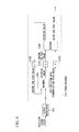
- FIG. 13 is a block diagram that illustrates a configuration of a conventional multi-carrier-code-divided multiplexing system.
- FIG. 13 shows a transmitting device 100 including a modulator (MOD) 101 that modulates transmitting data and outputs modulated symbols. Description is given based on the symbols as b [n] as follows: However, n is a mark showing time, giving a modulated symbol number.
- a quadrature phase shift keying quadri-phase shift keying (QPSK) system is used herein.
- a modulating symbol b [n] can obtain a signal point alignment on an IQ surface (that is a flat surface structuring with values that channel I (real numbers) and channel Q (imaginary numbers) can obtain), as illustrated in FIG. 14 .
- FIG. 14 indicates four standard signal points that the modulating symbol b [n] can obtain.
- a spreading and multiplexing unit 102 spreads modulating symbols in code, and multiplexes these modulated symbols.
- duple spread (spread ratio is 2, and one modulating symbol is spread into two sub-carriers) and duple multiplex (multiplex number is 2, mapping two modulating symbols to one sub-carrier) is used herein.
- a spread code a Walsh code is used.
- a Walsh code is generated from the Hadamard matrix.
- the Hadamard matrix is a diametric alignment in which rows and columns are at right angles of each other with +1 and ⁇ 1 as elements.
- the Walsh matrix can be obtained by realigning an ascending order in the number of times that a code is replaced with a column in the Hadamard matrix.
- the spread multiplex conversion matrix T 2 supporting the duple spread and the duple multiplex is expressed as formula (1).
- T 2 ( 1 1 1 - 1 ) ( 1 )
- a spreading and multiplexing unit 102 conducts duple spread and duple multiplex according to formula (2). As a result, two modulating symbols b [2n ⁇ 1] and b[2n] are outputted as two chip signals c 1 [n] and c 2 [n].
- a serial/parallel conversion unit (S/P) 103 converts two-system chip signal c 1 [n] and c 2 [n] as respective serial signal inputs into parallel signals.
- the parallel signal numbers are based on a ratio of sub-carrier numbers used for data transfer with a spread rate. In case the sub-carrier numbers are 512, for example, a spread rate is 2 and the parallel numbers are 256, which is given by a formula 512 divided by 2.
- An Inverse Fast Fourier Transform (IFFT) 104 provides a paralleled chip signal h k with Inverse Fast Fourier Transform processing, and converts it as the signal in a frequency region into a signal in a time region.
- the chip signals c 1 [n] and c 2 [n] of which n are the same are herein given a distance as sufficient as possible on the frequency region. By this, higher frequency diversity effects can be obtained.
- a parallel/serial conversion unit converts a signal in a time region after output of IFFT 104 into a serial signal.
- a guard interval insertion unit (+GI) 106 adds a guard interval to its serial signal.
- a guard interval is a signal that maintains orthogonal nature between sub-carriers even at a receiving side.
- a signal after the addition of the guard interval is sent by radio transmission together with a pilot signal (not illustrated herein).
- a pilot signal is used for estimating a channel at a receiving side.
- a guard interval removing unit ( ⁇ GI) 201 removes guard intervals from the signals received by radio transmission.
- An S/P 202 converts signals after removing guard intervals into parallel signals.
- a Fast Fourier Transform (FFT) 203 provides the paralleled chip signals with Inverse Fast Fourier Transform processing, and converts them from the signals in a frequency region into sub-carrier signals H k in a time region.
- the sub-carrier signal H k hereof includes changes of amplitude and a phase received in a channel.
- a channel estimation and MMSE correction unit 204 measures a state of channels according to receiving characteristics of pilot signals. The unit also measures a noise power density in a frequency band. Then the channel estimation and MMSE correction unit 204 conducts an equivalent processing using Minimum Means Square Errors (MMSE) according to the channel state and the noise power density.
- MMSE Minimum Means Square Errors
- H k ′ H k ⁇ A k * ⁇ A k ⁇ 2 + N 0 ( 3 )
- H k is the K th order of the sub-carrier signal that is input
- H k ′ is the K th order of the sub-carrier that is output
- a k is a channel stat of the sub-carrier number K
- N o is a noise power density.
- the P/S 205 converts the sub-carrier signal H k into a serial signal, and outputs the signal as a combination of (c 1 ′ [n] and c 2 ′ [n]) the chip signal duple spread.
- An inverse spreading unit 206 obtains a correlation of a chip signal and a spread code, and then restores the modulated symbol that was spread. More specifically, an operation as expressed formula (4) is arranged.
- the modulated symbol spread in a chip signal c 1 [n] that supports the sub-carrier signal H k in the number K under K/2 ⁇ k in chase where the sub-carrier numbers are K is also spread into a sub-carrier signal H k+K/2 , that also supports the chip signal C 2 [n].
- background noises mixed into these two sub-carrier signals H k and H k+k/2 are respectively n k , and n k+k/2 , a formula (5) is satisfied.
- the first section of the right-hand member is a section related to an intended modulated symbol b [n ⁇ 1]
- the second section is a section related to an interfering modulated symbol b [n] (the section related to interference noises)
- the third section is a section related to background noises.
- Supposing relations of the formula (7) can be satisfied herein, the background noises are only mixed as noise components without mutual interference of the modulated symbols b [n ⁇ 1] and b [n].
- the receiving accuracy thus, becomes deteriorated in the modulator 207 .
- a conventional MC-CDM system cannot avoid deterioration of receiving characteristics affected by inter-code interference caused by frequency selectivity of a radio channel, even in case where an MMSE-based equalization technology, in which the characteristics are believed to be most excellent, is applied.
- the present invention is aimed to provide a multi-carrier code dividing multiplex transfer system capable of preventing affects of the inter-code interference and promoting to improve the receiving characteristics, and a method and a receiving unit for the same.
- the multi-carrier code dividing multiplex transfer system of the present invention is equipped with a demodulator for discriminating transmitted signals according to a receiving signal point composed of a combination of receiving values in a spread state of sub-carriers in a range where one modulated symbol is spread, and a reference signal composing values that can be taken by the combination of the receiving values in the spread state, in the multi-carrier code dividing multiplex transfer system that code-spreads modulated symbols in a frequency direction, frequency-multiplexes and transfers them in a plurality of the sub-carriers.
- the multi-carrier code dividing multiplex transfer system of the present invention includes the demodulator for providing the decision according to probability of a specific value that the modulated symbol could take as well.
- the multi-carrier code dividing multiplex transfer system of the present invention is equipped with a decoder for applying error correction codes, decoding the error correction codes from the result of decisions from the demodulator, and giving feedback correctness of decoding results obtained in the decoding process as the probability.
- the multi-carrier code dividing multiplex transfer system of the present invention uses a rotating orthogonal code as a spread code; the rotating orthogonal code is composed of a trigonometrical function that includes adjustment parameters as arguments.
- the method for the multi-carrier code dividing multiplex transfer system of the present invention in which code-spreads modulated symbols in a frequency direction, frequency-multiplexes and transfers them, includes a demodulating step for discriminating transmitted signals according to a receiving signal point composed of a combination of receiving values in a spread state of sub-carriers in a range where one modulated symbol is spread, and a reference signal point that can be taken by the combination of the receiving values in the spread state.
- the receiving device of the present invention is equipped with a demodulator for discriminating transmitted signals according to a receiving signal point composed of a combination of receiving values in a spread state of sub-carriers in a range where one modulated symbol is spread, and a reference signal composing values that can be taken by the combination of the receiving values in the spread state, and in the receiving device that receives transferred signals of which modulated symbols are code-spread and frequency-multiplexed by a plurality of sub-carriers modulated symbols in a frequency direction.
- the multi-carrier code dividing multiplex transfer system of the present invention may include the demodulator equipped with: a reference signal point preparation unit for preparing a coordinate of reference signals according to a type of modulating method, a type of spread multiplexing method and information on receiving stress of the sub-carrier signals; a receiving signal point preparation unit for preparing a coordinate of the receiving signal from the combination of the receiving values in the spread state; and a likelihood calculation unit for calculating the likelihood according to the coordinate of the reference signal point and the coordinate of the receiving signal point.
- a reference signal point preparation unit for preparing a coordinate of reference signals according to a type of modulating method, a type of spread multiplexing method and information on receiving stress of the sub-carrier signals
- a receiving signal point preparation unit for preparing a coordinate of the receiving signal from the combination of the receiving values in the spread state
- a likelihood calculation unit for calculating the likelihood according to the coordinate of the reference signal point and the coordinate of the receiving signal point.
- the multi-carrier code dividing multiplex transfer system of the present invention may separate the coordinate of the reference signal point, the coordinate of the receiving signal point and the likelihood into real numbers and imaginary numbers, and then respectively calculates them.
- the step of demodulating may further include the steps of: preparing a coordinate of reference signals according to a type of modulating method, a type of spread multiplexing method and information on receiving stress of the sub-carrier signals; preparing a coordinate of the receiving signal from the combination of the receiving values in the spread state; and calculating the likelihood according to the coordinate of the reference signal point and the coordinate of the receiving signal point.
- the method for the multi-carrier code dividing multiplex transfer system of the present invention may include the step of respectively calculating the coordinate of the reference signal point, the coordinate of the receiving signal point and the likelihood with separating into real numbers and imaginary numbers.
- the demodulator may include: a reference signal point preparation unit for preparing a coordinate of reference signals according to a type of modulating method, a type of spread multiplexing method and information on receiving stress of the sub-carrier signals; a receiving signal point preparation unit for preparing a coordinate of the receiving signal from the combination of the receiving values in the spread state; and a likelihood calculation unit for calculating the likelihood according to the coordinate of the reference signal point and the coordinate of the receiving signal point.
- the coordinate of the reference signal point, the coordinate of the receiving signal point and the likelihood are separated into real numbers and imaginary numbers, and then they are respectively calculated.
- the present invention can demodulate the signals in a spread state as it is without inverse spread, demodulation can be promoted without affects of the inter-code interference. As a result, demodulating accuracy can be improved and receiving characteristics can also be improved.
- FIG. 1 is a block diagram that illustrates a configuration of the receiving device 1 of the multi-carrier-code-divided multiplexing system according to the first embodiment of the present invention.
- FIG. 2 is a complex space coordinate diagram that illustrates reference signal points of the same embodiment.
- FIG. 3 is an explanatory diagram that explains direct demodulating processings of the same embodiment.
- FIG. 4 is a block diagram that illustrates a configuration of a multi-carrier-code-divided multiplexing system according to the second embodiment of the present invention.
- FIG. 5 is a block diagram that illustrates a configuration of a turbo encoding device 110 as an encoding device, as illustrated in FIG. 4 .
- FIG. 6 is a block diagram that illustrates a configuration of a turbo decoder 210 as a decoder, as illustrated in FIG. 4 .
- FIG. 7 is a block diagram that illustrates a configuration of an LDPC decoder 210 as a decoder, as illustrated in FIG. 4 .
- FIG. 8 is a block diagram that illustrates a configuration of a multi-carrier-code-divided multiplexing system according to the third embodiment of the present invention.
- FIG. 9 is a block diagram that illustrates one implementation example of a turbo decoder 210 b as a decoder, as illustrated in FIG. 8 .
- FIG. 10 is a block diagram that illustrates a configuration of a multi-carrier-code-divided multiplexing system according to the fourth embodiment of the present invention.
- FIG. 11 is a block diagram that illustrates one implementation example of a turbo decoder 210 c as a decoder, as illustrated in FIG. 10 .
- FIG. 12 is a complex space coordinate diagram that illustrates reference signal points of the other embodiment according to the present invention.
- FIG. 13 is a block diagram that illustrates a configuration of a conventional multi-carrier-code-divided multiplexing system.
- FIG. 14 is a diagram that illustrates a standard signal point of the modulated symbols for the QPSK system.
- FIG. 15 is a block diagram that illustrates a configuration of a multi-carrier-code-divided multiplexing system for describing one implementation example of a director demodulator 12 a according to the embodiment of the present invention.
- FIG. 16 is a block diagram that illustrates a configuration of a direct demodulator 12 a according to the embodiment of the present invention.
- FIG. 17 shows examples of a reference signal point and a receiving signal point prepared by the direct demodulator 12 , as illustrated in FIG. 16 .
- FIG. 1 is a block diagram that illustrates a configuration of the receiving device 1 of the multi-carrier-code-divided multiplexing system according to the first embodiment of the present invention.
- FIG. 1 shows units corresponding to each of those in a conventional receiving device 200 (refer to FIG. 13 ) with the same reference numerals denoted, and their descriptions are omitted.
- the multi-carrier code dividing multiplex transfer system of the present embodiment is similar to the conventional transmitting device 100 (refer to FIG. 13 ), using QPSK system as its modulating system with spread ratio 2 , and the multiplexing numbers are 2.
- a receiving device 1 includes a channel estimation and phase correction unit 11 for measuring a state of channels according to receiving characteristics of pilot signals.
- the device corrects the amount of phase change received by the channel every sub-carrier.
- a sub-carrier signal H k ′′ (a signal supporting the sub-carrier in the K th order) becomes a signal with a background noise n k further added to the signal that the amplitude value a k (real number) in the channel multiplied by the sub-carrier signal h k in the k th order at the time of transmission, and it is expressed in a formula (8).
- H k ′′ a k h k +n k (8)
- the sub-carrier signal, H k ′′ is converted into a serial signal by the P/S 205 , and output as a combination (c 1 ′′ [n] and c 2 ′′ [n]) of the chip signal duple spread.
- a direct demodulator (D-DEM) 12 directly demodulates from the combination (c 1 ′′ [n] and c 2 ′′ [n]) of the chip signal duple spread. In other words, the direct demodulator obtains receiving data without applying inverse spread.
- the direct demodulating process is described by referring to FIGS. 2 and 3 .
- FIG. 2 is a complex space coordinate diagram showing a reference signal point of the present embodiment, while FIG. 2 (1) shows a real number space and FIG. 2 (2) shows an imaginary number space.
- FIG. 2 shows the values that the combination of c 1 ′′ [n] and 2 ′′ [n] can take (reference signal points) as separated into a real number supporting channel I ( FIG. 2 (1)), and an imaginary number supporting channel Q ( FIG. 2 (2)).
- Re (z) denotes the real number of complex number z (channel I component)
- Im (z) denotes the imaginary number of complex number z (channel Q component).
- the combination of c 1 ′′ [n] and c 2 ′′ [n] is a combination of receiving values in a spread state of the sub-carriers within the range where one modulated symbol is spread.
- a value (reference signal point) that its combination of c 1 ′′ [n] and c 2 ′′ [n] can take is shown in the above formula (2).
- the receiving device of the present invention discriminates transmitted signals according to a receiving signal point composed of a combination of receiving values in a spread state of sub-carriers in a range where one modulated symbol is spread, and a reference signal composing values that can be taken by the combination of the receiving values in the spread state of the sub-carriers.
- FIG. 3 shows one example of a receiving signal point (in only real number).
- the example in FIG. 3 shows a combined value (receiving signal point 301 ) of each real number (channel I component) in c 1 ′′ [n] and c 2 ′′ [n]. Its value 301 is in the position closest to “01” out of four reference signal points “00”, “01”, “10” and “11”.
- MC-CDM system demodulation can process demodulation in a spread state as it is without inverse spread applied. Therefore, no interference components are mixed while it conventionally occurs at the time of inverse spread, resulting in no inter-code interference affected at the time of demodulating the present embodiment. As a result, demodulating accuracy can be improved and receiving characteristics improves.
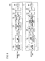
- FIG. 4 is a block diagram that illustrates a configuration of a multi-carrier-code-divided multiplexing system according to the second embodiment of the present invention.
- the second embodiment is a deformation example of the above first embodiment, with error correction codes further applied.
- a transmitting device 100 a includes an encoding device (ENC) mounted while another configuration is similar to that of a transmitting device 100 , as illustrated in FIG. 13 .
- a transmitting device 100 a includes an encoding device 110 that adds error correction codes to the transmitting data. Its encoding data is input to a modulator 101 from the encoding device 110 . Further processings are similar to those of the transmitting device, as illustrated in FIG. 13 .
- a receiving device 1 a includes a decoder (DEC) 210 mounted.
- DEC decoder
- a direct demodulator 12 a changes the processing method for a decoder 210 from that for the direct demodulator 12 in the above FIG. 1 .
- Other configurations are similar to those of the receiving device, as illustrated in FIG. 1 .
- a decoder 210 conducts error correction processing according to the signals demodulated by the direct demodulator 12 a , and outputs receiving data.
- the direct demodulator 12 a outputs soft-decision input signals used for its error correction processing (likelihood per bit). Operation of its direct demodulator 12 a is described with an example of the above FIG. 3 .
- a receiving signal point 301 is a receiving signal point supporting two bits of Re (b [2n ⁇ 1]) and Re (b [2n]).
- Re b [2n ⁇ 1]
- Re b [2n]
- its likelihood p is expressed in a formula (9).
- x Re (b [2n ⁇ 1])
- y Re (b [2n])
- d xy 2 expresses a square distance between a receiving signal point and a reference signal point (xy)
- ⁇ 2 expresses noise power per sub-carrier.
- the aforementioned second embodiment can also be applied to a system using error correction codes.
- the accuracy of demodulation can be expected to improve because the modulator symbol can conduct a decoding with probability integration according to prior probability that can take a specific value.
- FIG. 5 is a block diagram that illustrates a configuration of a turbo encoding device 110 as an encoding device, as illustrated in FIG. 4 .
- the configuration illustrated in FIG. 5 is well known.
- the turbo encoding device 110 is equipped with two element coding devices 1101 and 1102 that encode with two element codes.
- the element coding device 1101 generates a parity bit a 1 from transmitting information.
- An interleaver 1103 complicates the orders of input transmitting information bits.
- the element coding device 1102 generates a parity bit a 2 from the transmitting information after being output from the interleaver 1103 .
- the parity bits a 1 and a 2 are therefore generated from the same transmitting information bit.
- the order of inputting the transmitting information bits is complicated between the element coding devices 1101 and 1102 .
- the turbo encoding device 110 outputs a total of three bits, such as the input transmitting information bit and parity bits a 1 and a 2 , as the encoding data.
- FIG. 6 is a block diagram that illustrates a configuration of a turbo decoder 210 as a decoder, as illustrated in FIG. 4 .
- the direct demodulator 12 a outputs soft-decision data of the modulated symbol per bit as soft-decision data.
- the soft-decision data is inputted in the turbo decoder 210 as a communication path value.
- the turbo decoder 210 configured as supporting the turbo encoding device 110 , as illustrated in FIG. 5 , is equipped with a decoder 2101 supporting an element coding device 1101 and a decoder 2102 supporting an element coding device 1102 . It should be noted that the configuration of the turbo decoder 210 in FIG. 6 is well known.
- the decoder 2101 first inputs both communication path values of the transmitting information bit and the parity bit a 1 .
- a prior value of the transmitting information bit is set as [1 ⁇ 2] (which is 0 in logarithmic likelihood).
- an exterior value of the transmitting information bit and an after-the-fact value are calculated.
- the exterior value is only used for the next processing at this stage.
- the exterior value after output from the decoder 2101 is complicated in the interleaver 2103 , and then the value is inputted in the decoder 2102 as a before-the-fact value. Both communication path values of the transmitting information bit and the parity bit a 2 are inputted to the decoder 2102 .
- a communication path value of the transmitting information bit hereof is inputted in the decoder 2102 after it is complicated in the interleaver 2104 , same as the exterior value after outputted from the decoder 2101 .
- the decoder 2102 outputs exterior values of the transmitting information bits and the after-the-fact values as a result of decoding processing.
- the after-the-fact values after being outputted from the decoder 2102 are bit-discriminated and outputted as receiving data (receiving information bits).
- the exterior value after outputted from the decoder 2102 is inverse-complicated in an inverse interleaver 2105 , and then the value is inputted in the decoder 2101 as a before-the-fact value. Calculation processing is accordingly implemented from the decoder 2101 again.
- the turbo encoding device 110 that outputs parity bits as they are
- various changes can be provided, such as puncturing the parity bits or applying channel interleaving to the transmitting information bits and the parity bits, so as to adjust the configuration of the turbo encoding device 210 to those changes.
- LDPC codes Low-Density Parity-Check Codes
- FIG. 7 is a block diagram that illustrates a configuration of an LDPC decoder 210 as a decoder, as illustrated in FIG. 4 .
- the configuration of the LDPC decoder 210 in FIG. 7 is well known.
- the direct demodulator 12 a outputs soft-decision data of the modulated symbol per bit as soft-decision data.
- the soft-decision data is inputted in the LDPC decoder 210 as a communication path value.
- the LDPC decoder 210 repeats calculating after-the-fact values, same as the turbo coding, as described above. As its decoding algorithm, Min Sum and Sum Product are typically known. Its repeated calculation is conducted until decoding results become correct code terms or the specified repeating number is reached.
- a row direction calculating unit 2201 first conducts row direction calculation to the input communication path values, and outputs before-the-fact values (or exterior values).
- exterior values or before-the-fact values
- exterior values inputted from a column direction calculating unit 2203 are referred.
- a code term estimating unit 2202 conducts term estimation according to communication path values after being outputted from a direct demodulator 12 a , and before-the-fact values (or exterior values) after being outputted from the row direction calculating unit 2201 , and outputs after-the-fact values.
- the column direction calculating unit 2203 conducts column direction calculation according to results of a decision by a maximum repeating number deciding unit 2213 , and outputs exterior values (or before-the-fact values).
- a bit decision unit 2211 conducts bit decision according to inputted after-the-fact values.
- a code checking unit 2212 judges a pass-fail of a code check from the result of the bit decision. In case the code check is passed, the result of the bit decision is outputted as receiving data (receiving information bits). Meanwhile, in case the code check is failed, the maximum repeating number deciding unit 2213 judges whether or not repeating numbers in the LDPC decoder 210 has reached to the maximum repeating number. In case it has reached to the maximum repeating number, the current result of the bit decision is outputted as receiving data (receiving information bits).
- the unit gives an instruction of repeating the operation to the LDPC decoder 210 .
- FIG. 8 is a block diagram that illustrates a configuration of a multi-carrier-code-divided multiplexing system according to the third embodiment of the present invention.
- the third embodiment is a deformation example of the above second embodiment, and the above prior probability ratio is calculated in the decoding process with turbo codes applied.
- a transmitting device 100 b includes a turbo encoding device 110 b mounted, while another configuration is similar to that of a transmitting device 100 , as illustrated in FIG. 13 .
- the transmitting device 100 b includes the turbo encoding device 110 b that adds to the transmitting data error correction codes related to the turbo codes.
- the encoding data is inputted to a modulator 101 from the turbo encoding device 110 b . Further processings are similar to those of the transmitting device, as illustrated in FIG. 13 .
- a receiving device 1 b includes a turbo decoder 210 b mounted.
- a direct demodulator 12 a receives the above prior probability ratio from the turbo decoder 210 b , same as the direct demodulator 12 a , as illustrated in above FIG. 4 .
- a decoder 210 b conducts decoding processing related to the turbo codes according to the signals demodulated by the direct demodulator 12 a , and outputs receiving data. Signals expressing correctness of the decoding result thereof are outputted to the direct modulator 12 a as a prior probability ratio.
- the prior ratios for example, after-the-fact values, exterior values, which are obtained in a decoding process related to the turbo codes, or values that both the after-the-fact values and exterior values are added are applicable.
- FIG. 9 is a block diagram that illustrates one implementation example of a turbo decoder 210 b as a decoder, as illustrated in FIG. 8 .
- FIG. 9 denotes the same codes to each of the units that correspond to those in FIG. 6 , and their descriptions are omitted.
- FIG. 6 shows that two direct demodulators 12 a (direct demodulators 12 a - 1 and 12 a - 2 ) are mounted.
- FIG. 9 shows the turbo decoder 210 b in which the after-the fact value after outputted from the decoder 2102 is inverse-complicated in an inverse interleaver 2110 , thereafter, the value is directly inputted to the direct demodulator 12 a - 1 as a prior probability of a modulated symbol.
- the soft-decision data (communication path value) used at the time of executing repeated calculation processing from the decoder 2101 are accordingly reflected and updated with the prior probability of the modulated symbol by the direct demodulator 12 a - 1 , and it is expected that accuracy is improved better than that of the soft-decision data (communication path value) in the previous time.
- FIG. 9 also shows that the direct demodulator 12 a - 2 uses the after-the-fact value (prior probability) after outputted from the decoder 2101 and updates communication path values that are inputted to the decoder 2102 .
- the communication path values are updated according to the prior probability rate of each information bit in the update processing.
- correctness of the transmitting information bits obtained at the decoder 2102 allows the communication path values delivered to the decoder 2102 to be updated, resulting in accuracy improvement of the communication path values inputted to the decoder 2102 available.
- the performance of error correction improves and error transfer can be further prevented.
- the present invention applied to a system using turbo codes is capable of obtaining prior probability in which a modulated symbol can take a specific value in its decoding process, and contributing to improving demodulating accuracy.
- FIG. 10 is a block diagram that illustrates a configuration of a multi-carrier-code-divided multiplexing system according to the fourth embodiment of the present invention.
- the fourth embodiment is a deformation example of the above second embodiment, and the above prior probability ratio is calculated in the Low-Density Parity-Check Codes (LDPCs) applied.
- LDPCs Low-Density Parity-Check Codes
- a transmitting device 100 c includes a turbo encoding device 110 c mounted while another configuration is similar to that of a transmitting device 100 , as illustrated in FIG. 13 .
- the transmitting device 100 c includes the LDPC encoding device 110 c that adds to the transmitting data error correction codes related to the LDPC codes. Its encoding data is inputted to a modulator 110 c from the LDPC encoding device 110 c . Further processings are similar to those of the transmitting device, as illustrated in FIG. 13 .
- a receiving device 1 c includes an LDPC decoder 210 c mounted.
- a direct demodulator 12 a receives the above prior probability ratio from the LDPC 210 c , same as the direct demodulator 12 a , as illustrated in above FIG. 4 .
- a decoder 210 c conducts decoding processing related to the LDPC codes according to the signals demodulated by the direct demodulator 12 a , and outputs receiving data. Signals expressing correctness of the decoding result thereof are outputted to the direct modulator 12 a as a prior probability ratio.
- the prior ratios for example, after-the-fact values, obtained in a decoding process related to the LDPC codes, are applicable.
- FIG. 11 is a block diagram that illustrates one implementation example of a turbo decoder 210 c as a decoder, as illustrated in FIG. 10 .
- FIG. 11 denotes the same codes to each of the units that correspond to those in FIG. 7 , and their descriptions are omitted.
- FIG. 11 shows that the after-the-fact value after outputted from a code term estimating unit 2202 of an LDPC decoder 210 c is fed back to a direct demodulator 12 a as a prior probability.
- soft-decision data (communication path value) from the direct demodulator 12 a are accordingly reflected and updated with the prior probability of the modulated symbol by the direct demodulator 12 a , and it is expected that accuracy is improved better than that of the soft-decision data (communication path value) in the previous time.
- the performance of error correction accordingly improves and error transfer can be further prevented.
- the present invention applied to a system using LDPC codes is capable of obtaining prior probability in which a modulated symbol can take a specific value in its decoding process, and contributing to improving demodulating accuracy.
- QPSK Phase Shift Keying
- Quadrature Amplitude Modulation Quadrature Amplitude Modulation
- the present invention is also applicable to arbitral spread ratio, and multiplex numbers.
- the present invention is applicable to various spread codes.
- the formula (10) is a spread multiplexing conversion matrix supporting when the spread ratio is 2 N and the multiplex numbers are 2 N .
- T 2 N ( T 2 N - 1 ⁇ cos ⁇ ( p N ) T 2 N - 1 ⁇ sin ⁇ ( p N ) - T 2 N - 1 ⁇ sin ⁇ ( p N ) T 2 N - 1 ⁇ cos ⁇ ( p N ) ) ( 10 )
- the formula (11) shows the spread multiplexing conversion matrix T 2 , which supports in case the spread ratio is 2 and the multiplex numbers are 2, while the formula (12) shows the spread multiplexing conversion matrix T 4 , which supports in case the spread ratio is 4 and the multiplex numbers are 4.
- T 2 ( cos ⁇ ( p 1 ) sin ⁇ ( p 1 ) - sin ⁇ ( p 1 ) cos ⁇ ( p 1 ) ) ⁇ ( 11 )
- FIG. 12 An alignment of a reference signal point in case of using the rotating orthogonal codes (spread multiplexing conversion matrix T 2 ), as expressed in the above formula (11), is illustrated in FIG. 12 .
- FIG. 12 illustrates those in examples supporting the above FIG. 2 (1).
- the alignment of a reference signal point in case of using rotating orthogonal codes in the above formula (11) is a position rotated from an alignment of the reference signal point in case of FIG. 2 (1) only to an angle of ⁇ /4 ⁇ p (radian).
- FIG. 12 shows an alignment of the real numbers (channel I), it is also the same as in the imaginary numbers.
- T 2 ⁇ ( p ) ( cos ⁇ ( p ) sin ⁇ ( p ) - sin ⁇ ( p ) cos ⁇ ( p ) ) ( 13 )
- T 4 ⁇ ( p 1 ⁇ ⁇ p 2 ⁇ ⁇ p 3 ⁇ ⁇ p 4 ) ( T 2 ⁇ ( p 1 ) ⁇ cos ⁇ ( p 4 ) T 2 ⁇ ( p 2 ) ⁇ sin ⁇ ( p 4 ) - T 2 ⁇ ( p 3 ) ⁇ sin ⁇ ( p 4 ) T 2 ⁇ ( p 2 + p 3 - p 1 ) ⁇ cos ⁇ ( p 4 ) ) ( 14 )
- an angle of P N as an argument of trigonometrical function in the rotating orthogonal codes of the above formula (10) is an adjustment parameter. Diversity effects and inter-code interference can be adjusted by a set value of the adjustment parameter PN, and stabilizing transfer quality can be promoted.
- the present embodiment includes a channel estimation and phase correction unit 11 that detects receiving stress information ra 1 and ra 2 in the sub-carrier.
- the receiving stress information ra 1 expresses receiving stress of the sub-carrier signal that supports a chip signal c 1 [n].
- the receiving stress information ra 2 expresses receiving stress of the sub-carrier signal that supports a chip signal c 2 [n].
- the receiving stress information ra 1 and ra 2 are inputted to a direct demodulator 12 a .
- receiving stress information for example, receiving power of the sub-carrier signal, or a value expressing receiving amplification can be used.
- FIG. 16 is a block diagram that illustrates a configuration example of a direct demodulator 12 a .
- the direct demodulator 12 a has a reference signal point preparation unit 1201 , a receiving signal point preparation unit 1202 , and two likelihood calculation units 1203 .
- the likelihood calculation units 1203 are separately mounted as the unit for calculating the real numbers p_Re (b) of the likelihood, and the unit for calculating the imaginary numbers p_Im (b) of the likelihood.
- the reference signal point preparation unit 1201 prepares coordinates of the reference signals according to the type of modulating system, type of spread multiplexing system and receiving stress information ra 1 and ra 2 .
- the coordinates of the reference signal points are separately prepared for the real numbers (channel I component) and for the imaginary numbers (channel Q component).
- FIG. 17 illustrates an example of a reference signal point prepared by the reference signal point preparation unit 1201 .
- An example in FIG. 17 shows a reference signal point prepared using QPSK system as a modulation system and dual multiplex of duple spread with Walsh codes, indicating “00”, “01”, and “11” of the reference signal points for the real numbers.
- the reference signal point preparation unit 1201 calculates the coordinates of “00” and “11” components (in horizontal axis in FIG.
- FIG. 17 shows that the receiving stress indicated by the receiving stress information ra 1 is larger than that indicated by the receiving stress information ra 2 .
- the coordinates of “00” and “11” components supporting the chip signal c 1 [n] are larger than those of “01” and “10” components supporting the chip signal c 2 [n].
- the receiving signal point preparation unit 1202 prepares coordinates of the receiving signal points from the combination of chip signals (c 1 ′′ [n] and c 2 ′′ [n]).
- the receiving signal points are separately prepared as the real numbers (channel I component) and as the imaginary numbers (channel Q component). Coordinates of the receiving signal points are adjusted to the coordinates system of the reference signal points.
- the real numbers of the receiving signal points are combinations of c 1 ′′ [n] in the real numbers and c 2 ′′ [n] in the real numbers.
- the imaginary numbers of the receiving signal points are combinations of c 1 ′′ [n] in the imaginary numbers and c 2 ′′ [n] in the imaginary numbers.
- FIG. 17 shows an example of the receiving signal point in the real numbers (as marked with x in FIG. 17 ).
- Coordinates of the reference signal points for the real numbers are inputted to the likelihood calculation unit 1203 for calculating the real numbers p_Re (b) in the likelihood p from the reference signal preparation unit 1201 , and coordinates of the receiving signal points in real numbers are inputted from the receiving signal points preparation unit 1202 .
- Coordinates of the reference signal points for the imaginary numbers are inputted to the likelihood calculation unit 1203 for calculating the imaginary numbers p_Im (b) in the likelihood p from the reference signal preparation unit 1201 , and coordinates of the receiving signal points in imaginary numbers are inputted from the receiving signal points preparation unit 1202 .
- the likelihood calculation unit 1203 calculates the square of a distance between the coordinates of the reference signal points and the coordinates of the receiving signal points, and computes likelihood (the real numbers p_Re (b) or the imaginary numbers p_Im (b)) from the square distance according to the above formula (9).
- the likelihood p as the result of computation (the real numbers p_Re (b) and the imaginary numbers p_Im (b)) is inputted to the decoder 210 .
- the present invention can be applied to a multi-carrier code dividing multiplex transfer system that obtains frequency diversity effects by means of using orthogonal codes and frequency-multiplexing with a plurality of the sub-carriers the signals spread in frequency direction, and demodulation can be provided as in a spread state without inverse spread, the demodulation can be promoted without any affects of inter-code interference. As a result, demodulating accuracy can be improved and receiving characteristics can also be improved.
Landscapes
- Engineering & Computer Science (AREA)
- Signal Processing (AREA)
- Computer Networks & Wireless Communication (AREA)
- Power Engineering (AREA)
- Digital Transmission Methods That Use Modulated Carrier Waves (AREA)
- Error Detection And Correction (AREA)
Abstract
Description
|A k|=| A k+K/2| (7)
H k ″=a k h k +n k (8)
In case of Re (c1″ [n] c2″ [n])=“00”, Re (b [2n−1] b [2n]=“+1+1”,
In case of Re (c1″ [n] c2″ [n])=“01”, Re (b [2n−1] b[2n]=“+1−1”,
In case of Re (c1″ [n] c2″ [n])=“10”, Re (b [2n−1] b[2n]=“−1+1” and
In case of Re (c1″ [n] c2″ [n])=“11”, Re (b [2n−1] b[2n]=“−1−1”.
In case of Im (c1″ [n] c2″ [n])=“00”, Im (b [2n−1] b[2n]=“+1+1”,
In case of Im (c1″ [n] c2″ [n])=“01”, Im (b [2n−1] b[2n]=“+1−1”,
In case of Im (c1″ [n] c2″ [n])=“10”, Im (b [2n−1] b[2n]=“−1+1” and
In case of Im (c1″ [n] c2″ [n])=“11”, Im (b [2n−1] b[2n]=“−1−1”.
Claims (12)
Applications Claiming Priority (3)
| Application Number | Priority Date | Filing Date | Title |
|---|---|---|---|
| JP2005281550 | 2005-09-28 | ||
| JP2005-281550 | 2005-09-28 | ||
| PCT/JP2006/319285 WO2007037320A1 (en) | 2005-09-28 | 2006-09-28 | Multi-carrier code dividing multiplex transfer system and method, and receiving device |
Publications (2)
| Publication Number | Publication Date |
|---|---|
| US20100142589A1 US20100142589A1 (en) | 2010-06-10 |
| US7974330B2 true US7974330B2 (en) | 2011-07-05 |
Family
ID=37899744
Family Applications (1)
| Application Number | Title | Priority Date | Filing Date |
|---|---|---|---|
| US11/992,525 Expired - Fee Related US7974330B2 (en) | 2005-09-28 | 2006-09-28 | Multi-carrier code dividing multiplex transfer system and method, and receiving device |
Country Status (3)
| Country | Link |
|---|---|
| US (1) | US7974330B2 (en) |
| JP (1) | JP4574680B2 (en) |
| WO (1) | WO2007037320A1 (en) |
Families Citing this family (4)
| Publication number | Priority date | Publication date | Assignee | Title |
|---|---|---|---|---|
| JP5220816B2 (en) * | 2010-08-19 | 2013-06-26 | Kddi株式会社 | Transmission method |
| US9590758B2 (en) | 2015-05-19 | 2017-03-07 | Samsung Electronics Co., Ltd. | Transmitting apparatus and mapping method thereof |
| US9602232B2 (en) | 2015-05-19 | 2017-03-21 | Samsung Electronics Co., Ltd. | Transmitting apparatus and mapping method thereof |
| CN113794478A (en) * | 2021-09-06 | 2021-12-14 | 深圳市极致汇仪科技有限公司 | LDPC (Low Density parity check) step-by-step decoding method and system based on noise power |
Citations (6)
| Publication number | Priority date | Publication date | Assignee | Title |
|---|---|---|---|---|
| US6005887A (en) | 1996-11-14 | 1999-12-21 | Ericcsson, Inc. | Despreading of direct sequence spread spectrum communications signals |
| US20020191710A1 (en) * | 2001-06-08 | 2002-12-19 | Jeckeln Ernesto G. | Adaptive predistortion device and method using digital receiver |
| WO2004082200A1 (en) | 2003-03-10 | 2004-09-23 | Docomo Communications Laboratories Europe Gmbh | Apparatus and method for detecting a group of received symbols |
| US20040208232A1 (en) * | 2001-11-26 | 2004-10-21 | Hiroaki Sudo | Radio transmission apparatus and radio transmission method |
| US20060018276A1 (en) * | 2004-07-10 | 2006-01-26 | Samsung Electronics Co., Ltd. | Resource allocation method for downlink transmission in a multicarrier-based CDMA communication system |
| US7564906B2 (en) * | 2004-02-17 | 2009-07-21 | Nokia Siemens Networks Oy | OFDM transceiver structure with time-domain scrambling |
-
2006
- 2006-09-28 WO PCT/JP2006/319285 patent/WO2007037320A1/en active Application Filing
- 2006-09-28 JP JP2007537671A patent/JP4574680B2/en not_active Expired - Fee Related
- 2006-09-28 US US11/992,525 patent/US7974330B2/en not_active Expired - Fee Related
Patent Citations (8)
| Publication number | Priority date | Publication date | Assignee | Title |
|---|---|---|---|---|
| US6005887A (en) | 1996-11-14 | 1999-12-21 | Ericcsson, Inc. | Despreading of direct sequence spread spectrum communications signals |
| JP2001504655A (en) | 1996-11-14 | 2001-04-03 | エリクソン インコーポレイテッド | Despreading of direct sequence spread spectrum communication signals. |
| US20020191710A1 (en) * | 2001-06-08 | 2002-12-19 | Jeckeln Ernesto G. | Adaptive predistortion device and method using digital receiver |
| US20040208232A1 (en) * | 2001-11-26 | 2004-10-21 | Hiroaki Sudo | Radio transmission apparatus and radio transmission method |
| WO2004082200A1 (en) | 2003-03-10 | 2004-09-23 | Docomo Communications Laboratories Europe Gmbh | Apparatus and method for detecting a group of received symbols |
| JP2006514803A (en) | 2003-03-10 | 2006-05-11 | ドコモ コミュニケーションズ ラボラトリーズ ヨーロッパ ゲーエムベーハー | Method and apparatus for detecting received symbol groups |
| US7564906B2 (en) * | 2004-02-17 | 2009-07-21 | Nokia Siemens Networks Oy | OFDM transceiver structure with time-domain scrambling |
| US20060018276A1 (en) * | 2004-07-10 | 2006-01-26 | Samsung Electronics Co., Ltd. | Resource allocation method for downlink transmission in a multicarrier-based CDMA communication system |
Non-Patent Citations (3)
| Title |
|---|
| KDDI, "Enhancement of Distributed Mode for Maximizing Frequency Diversity," R1-051261, United Stats, 3GPP TSG RAN WG1#42 bis, Oct. 10, 2005, URL, http://www.3gpp.org/ftp/tsg-ran/WG1-RL1/TSGR1-42bis/Docs/R1-051261zip. |
| KDDI, "Enhancement of Distributed Mode for Maximizing Frequency Diversity," R1-051261, United Stats, 3GPP TSG RAN WG1#42 bis, Oct. 10, 2005, URL, http://www.3gpp.org/ftp/tsg—ran/WG1—RL1/TSGR1—42bis/Docs/R1-051261zip. |
| Miyazaki et al., "A Study on Forward Link Capacity in MC-CD-MA Cellular System with MMSEC Receiver", IEICE Trans. Commun, Feb. 2005 (E88)(2) 585-593. |
Also Published As
| Publication number | Publication date |
|---|---|
| JP4574680B2 (en) | 2010-11-04 |
| US20100142589A1 (en) | 2010-06-10 |
| JPWO2007037320A1 (en) | 2009-04-09 |
| WO2007037320A1 (en) | 2007-04-05 |
Similar Documents
| Publication | Publication Date | Title |
|---|---|---|
| US10547479B2 (en) | Transmission apparatus and method, and reception apparatus and method | |
| KR100434473B1 (en) | Apparatus for decoding channel and method thereof in orthogonal frequency division multiplexing system | |
| US8577284B2 (en) | Cooperative reception diversity apparatus and method based on signal point rearrangement or superposition modulation in relay system | |
| JP5730964B2 (en) | Physical broadcast channel (PBCH) transmission for reliable antenna configuration detection | |
| US20060198292A1 (en) | Ofdm reception device and ofdm reception method | |
| US20100290568A1 (en) | Decoding frequency channelised signals | |
| US9548844B2 (en) | Communication device and communication system | |
| RU2608776C2 (en) | Radio receiving device and radio transmitting device | |
| WO2006126326A1 (en) | Reception device | |
| US8014463B2 (en) | Delay diversity and spatial rotation systems and methods | |
| CN1708935A (en) | Data detection and demodulation for wireless communication systems | |
| JP5697795B2 (en) | Wireless transmission device, wireless reception device, and data transmission method | |
| US8300521B2 (en) | Radio reception apparatus and radio reception method | |
| US7974330B2 (en) | Multi-carrier code dividing multiplex transfer system and method, and receiving device | |
| US7046617B2 (en) | Method and apparatus for an enhanced OFDM system | |
| Sodhi et al. | Preserving authenticity and integrity of distributed networks through novel message authentication code | |
| US20130039388A1 (en) | Communication systems and methods | |
| US8126075B2 (en) | Telecommunications method and system | |
| JP7054334B2 (en) | Transmitter, receiver and chip | |
| KR100885746B1 (en) | Apparatus and method for receiving signal in a communication system | |
| WO2009113763A1 (en) | Cooperative reception diversity apparatus and method based on signal point rearrangement or superposition modulation in relay system | |
| US20240097818A1 (en) | Signal processing | |
| JP2008035442A (en) | Multi-antenna receiver, multi-antenna transmitter, and multi-antenna communication system | |
| JP2004260322A (en) | Multicarrier wireless communication system, transmitter, and receiver | |
| JP2015186246A (en) | Communication system, transmitter, and receiver |
Legal Events
| Date | Code | Title | Description |
|---|---|---|---|
| AS | Assignment |
Owner name: KDDI CORPORATION,JAPAN Free format text: ASSIGNMENT OF ASSIGNORS INTEREST;ASSIGNORS:SUZUKI, TOSHINORI;MIYAZAKI, NORIAKI;REEL/FRAME:020822/0133 Effective date: 20080313 Owner name: KDDI CORPORATION, JAPAN Free format text: ASSIGNMENT OF ASSIGNORS INTEREST;ASSIGNORS:SUZUKI, TOSHINORI;MIYAZAKI, NORIAKI;REEL/FRAME:020822/0133 Effective date: 20080313 |
|
| STCF | Information on status: patent grant |
Free format text: PATENTED CASE |
|
| FEPP | Fee payment procedure |
Free format text: PAYOR NUMBER ASSIGNED (ORIGINAL EVENT CODE: ASPN); ENTITY STATUS OF PATENT OWNER: LARGE ENTITY |
|
| FPAY | Fee payment |
Year of fee payment: 4 |
|
| MAFP | Maintenance fee payment |
Free format text: PAYMENT OF MAINTENANCE FEE, 8TH YEAR, LARGE ENTITY (ORIGINAL EVENT CODE: M1552); ENTITY STATUS OF PATENT OWNER: LARGE ENTITY Year of fee payment: 8 |
|
| FEPP | Fee payment procedure |
Free format text: MAINTENANCE FEE REMINDER MAILED (ORIGINAL EVENT CODE: REM.); ENTITY STATUS OF PATENT OWNER: LARGE ENTITY |
|
| LAPS | Lapse for failure to pay maintenance fees |
Free format text: PATENT EXPIRED FOR FAILURE TO PAY MAINTENANCE FEES (ORIGINAL EVENT CODE: EXP.); ENTITY STATUS OF PATENT OWNER: LARGE ENTITY |
|
| STCH | Information on status: patent discontinuation |
Free format text: PATENT EXPIRED DUE TO NONPAYMENT OF MAINTENANCE FEES UNDER 37 CFR 1.362 |
|
| FP | Lapsed due to failure to pay maintenance fee |
Effective date: 20230705 |