US7972557B2 - Plasmon filter - Google Patents
Plasmon filter Download PDFInfo
- Publication number
- US7972557B2 US7972557B2 US11/897,526 US89752607A US7972557B2 US 7972557 B2 US7972557 B2 US 7972557B2 US 89752607 A US89752607 A US 89752607A US 7972557 B2 US7972557 B2 US 7972557B2
- Authority
- US
- United States
- Prior art keywords
- fluid
- plasmon
- energy
- openings
- filter element
- Prior art date
- Legal status (The legal status is an assumption and is not a legal conclusion. Google has not performed a legal analysis and makes no representation as to the accuracy of the status listed.)
- Active, expires
Links
- 239000012530 fluid Substances 0.000 claims abstract description 83
- 239000000463 material Substances 0.000 claims abstract description 47
- 238000000034 method Methods 0.000 claims abstract description 32
- 230000003319 supportive effect Effects 0.000 claims abstract description 10
- 238000001914 filtration Methods 0.000 claims description 17
- 244000052769 pathogen Species 0.000 claims description 2
- 230000001717 pathogenic effect Effects 0.000 claims description 2
- 230000008569 process Effects 0.000 description 17
- 239000000306 component Substances 0.000 description 15
- 239000000835 fiber Substances 0.000 description 14
- 238000002198 surface plasmon resonance spectroscopy Methods 0.000 description 13
- 238000004891 communication Methods 0.000 description 9
- 238000004590 computer program Methods 0.000 description 7
- 239000011941 photocatalyst Substances 0.000 description 7
- 239000004020 conductor Substances 0.000 description 6
- 238000005259 measurement Methods 0.000 description 6
- 239000000758 substrate Substances 0.000 description 6
- 238000006243 chemical reaction Methods 0.000 description 5
- 238000009826 distribution Methods 0.000 description 5
- 239000012620 biological material Substances 0.000 description 4
- 239000007788 liquid Substances 0.000 description 4
- XLYOFNOQVPJJNP-UHFFFAOYSA-N water Substances O XLYOFNOQVPJJNP-UHFFFAOYSA-N 0.000 description 4
- 241000894006 Bacteria Species 0.000 description 3
- 238000013459 approach Methods 0.000 description 3
- 238000010586 diagram Methods 0.000 description 3
- 238000005516 engineering process Methods 0.000 description 3
- 230000001788 irregular Effects 0.000 description 3
- 230000000670 limiting effect Effects 0.000 description 3
- 238000012986 modification Methods 0.000 description 3
- 230000004048 modification Effects 0.000 description 3
- 239000013307 optical fiber Substances 0.000 description 3
- 230000001954 sterilising effect Effects 0.000 description 3
- GWEVSGVZZGPLCZ-UHFFFAOYSA-N Titan oxide Chemical compound O=[Ti]=O GWEVSGVZZGPLCZ-UHFFFAOYSA-N 0.000 description 2
- 239000012503 blood component Substances 0.000 description 2
- 238000010276 construction Methods 0.000 description 2
- 239000003989 dielectric material Substances 0.000 description 2
- 229910052751 metal Inorganic materials 0.000 description 2
- 239000002184 metal Substances 0.000 description 2
- 102000039446 nucleic acids Human genes 0.000 description 2
- 108020004707 nucleic acids Proteins 0.000 description 2
- 150000007523 nucleic acids Chemical class 0.000 description 2
- 230000003287 optical effect Effects 0.000 description 2
- 239000002245 particle Substances 0.000 description 2
- 239000011148 porous material Substances 0.000 description 2
- 238000000746 purification Methods 0.000 description 2
- 238000004659 sterilization and disinfection Methods 0.000 description 2
- 241000700605 Viruses Species 0.000 description 1
- 239000006096 absorbing agent Substances 0.000 description 1
- 238000007792 addition Methods 0.000 description 1
- WYTGDNHDOZPMIW-RCBQFDQVSA-N alstonine Natural products C1=CC2=C3C=CC=CC3=NC2=C2N1C[C@H]1[C@H](C)OC=C(C(=O)OC)[C@H]1C2 WYTGDNHDOZPMIW-RCBQFDQVSA-N 0.000 description 1
- 238000003491 array Methods 0.000 description 1
- 230000005540 biological transmission Effects 0.000 description 1
- 230000000903 blocking effect Effects 0.000 description 1
- 239000011248 coating agent Substances 0.000 description 1
- 238000000576 coating method Methods 0.000 description 1
- 239000000470 constituent Substances 0.000 description 1
- 238000013270 controlled release Methods 0.000 description 1
- 230000008878 coupling Effects 0.000 description 1
- 238000010168 coupling process Methods 0.000 description 1
- 238000005859 coupling reaction Methods 0.000 description 1
- 239000013078 crystal Substances 0.000 description 1
- 230000001419 dependent effect Effects 0.000 description 1
- 238000013461 design Methods 0.000 description 1
- 238000010828 elution Methods 0.000 description 1
- 239000011521 glass Substances 0.000 description 1
- PCHJSUWPFVWCPO-UHFFFAOYSA-N gold Chemical compound [Au] PCHJSUWPFVWCPO-UHFFFAOYSA-N 0.000 description 1
- 229910052737 gold Inorganic materials 0.000 description 1
- 239000010931 gold Substances 0.000 description 1
- 230000002401 inhibitory effect Effects 0.000 description 1
- 230000003993 interaction Effects 0.000 description 1
- 230000002147 killing effect Effects 0.000 description 1
- 150000002632 lipids Chemical class 0.000 description 1
- 230000003137 locomotive effect Effects 0.000 description 1
- 230000007246 mechanism Effects 0.000 description 1
- 239000003607 modifier Substances 0.000 description 1
- 230000001699 photocatalysis Effects 0.000 description 1
- 238000007146 photocatalysis Methods 0.000 description 1
- 102000004169 proteins and genes Human genes 0.000 description 1
- 108090000623 proteins and genes Proteins 0.000 description 1
- 238000005086 pumping Methods 0.000 description 1
- 230000002441 reversible effect Effects 0.000 description 1
- 238000012552 review Methods 0.000 description 1
- 229910052709 silver Inorganic materials 0.000 description 1
- 239000004332 silver Substances 0.000 description 1
- 239000000126 substance Substances 0.000 description 1
- 230000000153 supplemental effect Effects 0.000 description 1
- 239000000725 suspension Substances 0.000 description 1
- 230000002123 temporal effect Effects 0.000 description 1
- 239000004408 titanium dioxide Substances 0.000 description 1
- 229960005486 vaccine Drugs 0.000 description 1
- 238000005406 washing Methods 0.000 description 1
Images


Classifications
-
- C—CHEMISTRY; METALLURGY
- C02—TREATMENT OF WATER, WASTE WATER, SEWAGE, OR SLUDGE
- C02F—TREATMENT OF WATER, WASTE WATER, SEWAGE, OR SLUDGE
- C02F1/00—Treatment of water, waste water, or sewage
- C02F1/30—Treatment of water, waste water, or sewage by irradiation
- C02F1/32—Treatment of water, waste water, or sewage by irradiation with ultraviolet light
-
- B—PERFORMING OPERATIONS; TRANSPORTING
- B01—PHYSICAL OR CHEMICAL PROCESSES OR APPARATUS IN GENERAL
- B01D—SEPARATION
- B01D29/00—Filters with filtering elements stationary during filtration, e.g. pressure or suction filters, not covered by groups B01D24/00 - B01D27/00; Filtering elements therefor
-
- B—PERFORMING OPERATIONS; TRANSPORTING
- B01—PHYSICAL OR CHEMICAL PROCESSES OR APPARATUS IN GENERAL
- B01D—SEPARATION
- B01D35/00—Filtering devices having features not specifically covered by groups B01D24/00 - B01D33/00, or for applications not specifically covered by groups B01D24/00 - B01D33/00; Auxiliary devices for filtration; Filter housing constructions
-
- B—PERFORMING OPERATIONS; TRANSPORTING
- B01—PHYSICAL OR CHEMICAL PROCESSES OR APPARATUS IN GENERAL
- B01D—SEPARATION
- B01D37/00—Processes of filtration
-
- B—PERFORMING OPERATIONS; TRANSPORTING
- B01—PHYSICAL OR CHEMICAL PROCESSES OR APPARATUS IN GENERAL
- B01D—SEPARATION
- B01D37/00—Processes of filtration
- B01D37/02—Precoating the filter medium; Addition of filter aids to the liquid being filtered
-
- C—CHEMISTRY; METALLURGY
- C02—TREATMENT OF WATER, WASTE WATER, SEWAGE, OR SLUDGE
- C02F—TREATMENT OF WATER, WASTE WATER, SEWAGE, OR SLUDGE
- C02F1/00—Treatment of water, waste water, or sewage
- C02F1/72—Treatment of water, waste water, or sewage by oxidation
- C02F1/725—Treatment of water, waste water, or sewage by oxidation by catalytic oxidation
-
- C—CHEMISTRY; METALLURGY
- C02—TREATMENT OF WATER, WASTE WATER, SEWAGE, OR SLUDGE
- C02F—TREATMENT OF WATER, WASTE WATER, SEWAGE, OR SLUDGE
- C02F1/00—Treatment of water, waste water, or sewage
- C02F1/005—Systems or processes based on supernatural or anthroposophic principles, cosmic or terrestrial radiation, geomancy or rhabdomancy
Definitions
- an apparatus comprises: a first element supportive of plasmon energy in a first energy range, the first element including a first plurality of openings; each of the openings in the first plurality of openings being configured to selectively pass a first portion of a first material; and each of the openings in the first plurality of openings having a respective characteristic dimension selected to provide substantial overlap of the passed first portion of the first material and the plasmon energy in the first energy range proximate the opening.
- a system comprises: a fluid filter supportive of evanescent energy and arranged to selectively pass a fluid; and an evanescent field generator arranged to produce the evanescent energy in a first frequency range within or proximate the fluid.
- a method comprises: filtering a fluid in a fluid flow region; generating a plasmon field in the fluid flow region; passing the fluid through the fluid flow region; and altering a property of the fluid via the plasmon field.
- a method comprises: providing a fluid to a fluid filter; creating plasmons on or adjacent to the filter; and altering the fluid via the plasmons.
- FIG. 1 is a schematic of a plasmon at a boundary.
- FIG. 2 is a schematic of a plasmon filter element.
- FIG. 3 is a schematic of a plasmon filter element in a housing.
- FIG. 4 is a schematic of an embodiment of two plasmon filter elements in a housing.
- FIG. 5 is a schematic of an embodiment of a system including a plasmon filter element.
- FIG. 6 is a schematic of a plasmon filter element having a mesh structure.
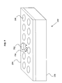
- FIG. 7 is a schematic of a plasmon filter including a MEMS.
- FIG. 8 is a flow chart depicting a method.
- FIGS. 9-12 depict variants of the flow chart of FIG. 8 .
- FIG. 13 is a flow chart depicting a method.
- FIGS. 14-16 depict variants of the flow chart of FIG. 8 .
- FIG. 1 shows a plasmon 102 at a boundary 104 of a material 106 having a negative real dielectric constant, such as a metal.
- the material or structure 108 forming the boundary 104 with the material 106 may be: air, vacuum, or its equivalent; a substantially homogeneous dielectric material; or a different material or structure.
- the boundary 104 although shown as being substantially continuous and planar, may have a different shape.
- the plasmon 102 although shown as including substantially exponential functions with a field maximum at the boundary 104 , may include only approximately exponential functions, may be described by a different function, and/or may have a field maximum someplace other than the boundary. Further, although the plasmon 102 is shown at a certain location on the boundary 104 for illustrative purposes, the spatial distribution of the plasmon 102 may be anything.
- the plasmon 102 includes an evanescent field 103 , where the evanescent field 103 is the portion of the plasmon 102 extending into the material or structure 108 .
- an evanescent field may occur outside of a surface plasmon.
- an evanescent field may occur at the boundary between two dielectrics where total internal reflection occurs.
- Exposing material to evanescent energy may result in altered properties of the material, and evanescent energy may be capable of sterilization or other types of interaction with biomaterials or other materials that may not be biomaterials. Further, evanescent energy may be used to photocatalyze a chemical reaction, as described in PLASMON PHOTOCATALYSIS, U.S. Ser. No. 11/185,925, which is incorporated herein by reference.
- evanescent energy may be utilized in a filter.
- a material may pass through one or more apertures in which plasmons exist.
- the function of the filter may depend on the type of reaction between the plasmon energy and the material that passes through the filter.
- Such a filter may be used, for example, in water purification, in purification of other consumables, as an air filter, or for other applications.
- FIG. 2 A first embodiment of a plasmon filter element 202 is shown in FIG. 2 .
- the filter element 202 includes a conductive layer 204 on a substrate 205 with an array of holes 206 through which a fluid may pass.
- the element 202 is configured to support plasmons 102 , and the size 208 and spacings 210 of the holes 206 are configured such that the interior of the holes 206 support plasmon energy. Thus, a fluid passing through the holes 206 is exposed to the plasmon energy.
- FIG. 2 shows the array of holes 206 as being a substantially regular array, in other embodiments the array may be an irregular array. Further, although the holes 206 are shown as being substantially the same size, in other embodiments the size 208 of the holes 206 may vary.
- the holes 206 although shown as being round, may be a different shape, including an irregular shape.
- the openings may be distributed in a variety of fashions including relatively random distributions similar to the openings of a sponge or other porous material such as is found in some commercially available water filters. Accordingly, in some approaches a series of passageways, serpentine paths, or other physical structures may permit passage of fluid while selectively inhibiting passage of particles, in a similar fashion.
- the conductive layer 204 shown in FIG. 2 may include gold, silver, and/or a different conductor. Although this conductive layer 204 is shown as being continuous and planar, in other embodiments the layer may have a different configuration. For example, the conductive layer 204 may include a grating patterned into it. Or, the conductive layer 204 may be patterned on just a portion of the substrate 205 .
- the substrate 205 may also have a different shape.
- the substrate may include glass, plastic, and/or a different material. Further, some embodiments may not include a substrate 205 , as in the case where the filter element 202 is made entirely of a conductor or where conductive material is distributed throughout the filter element 202 , for example.
- the filter element may be a substantially three-dimensional element, or the filter element may be thin enough such that the thickness of the element is substantially less than the other dimensions of the element, such as an array of wires.
- FIG. 2 has been described such that the volume of the holes 206 are supportive of plasmon energy, different embodiments may support different amounts of plasmon energy within the volume of the holes 206 .
- the substrate 205 includes a layer of dielectric with a thin coating of a conductor 204
- the concentration of the plasmon energy may be concentrated near the top of the hole 206 , and there may be very little plasmon energy throughout the volume of the hole 206 .
- the interior of the holes 206 may be coated with a conductor to increase the amount of plasmon energy in the hole 206 .
- FIG. 3 An embodiment of an apparatus 300 having a filter element 202 supported by a housing 302 is shown in FIG. 3 .
- the housing 302 is further configured to hold a material 304 .
- the material 304 is a liquid that flows into the filter element 202 .
- the portion of the material 304 that passes through the filter element 202 is the passed material 306 shown.
- the material 304 includes a first and second set of particulates 308 , 310 , where the first set of particulates 308 have a first size and a second set of particulates 310 have a second size.
- the first set of particulates 308 are generally of a size and shape that will typically pass through the holes 206 of the filter element 202
- the second set of particulates 310 typically have one or more dimensions sufficiently large that the particulates 310 do not pass through the holes 206 or are significantly impeded from passing through the holes 206 .
- the filter element 202 filters the material 304 by allowing a first portion of the material 304 (the portion that includes the first set of particulates 308 ) to pass through the filter element and by blocking a second portion of the material 304 (including the second set of particulates 310 ) from passing through the filter element, and it also filters the material 304 via the plasmon energy on the filter element.
- the illustrated first and second set of particulates 308 , 310 are an example of material that may be filtered by the filter element 202 , and other embodiments may include particulates having different shapes than those shown, a set of particulates having many different sizes and/or shapes, or other deviations from the particulates 308 , 310 shown in FIG. 3 .
- the material 304 to be filtered in FIG. 3 is a liquid, in other embodiments the material 304 to be filtered may be a gas or other type of material.
- the material 304 to be filtered may include (but is not limited to): water, air, a potable fluid, a dissolved substance, particulates, and/or a suspension.
- the material 304 to be filtered may include a biomaterial, which may include (but is not limited to): a vaccine, a pharmaceutical, nucleic acids, proteins, lipids, a blood component, or a different kind of biomaterial.
- the housing 302 although shown as being supportive of the materials 304 and 306 , in other embodiments may not be supportive of the material 304 to be filtered or the material 306 that has been filtered, and may only be supportive of the filter element 202 and/or other elements, or it may be supportive of only one of the materials 304 and 306 .
- FIG. 4 An embodiment of an apparatus 400 having two filter elements 202 and 402 supported by a housing 302 is shown in FIG. 4 .
- the two elements 202 , 402 are arranged in series such that a fluid passes through each of the elements.
- the first filter element 202 has a first hole size 208 and spacing 210 and the second filter element 402 has a second hole size 408 and spacing 410 .
- the filter elements 202 , 402 may in some embodiments include different materials or other structural variations such that they support plasmons having different frequencies.
- the apparatus 400 shown in FIG. 4 includes two elements 202 and 204 , in other embodiments there may be more than two elements.
- the elements are shown having different hole sizes 208 , 408 and spacings 210 , 410 , however in other configurations the differences between the elements 202 , 402 may be different than what is shown, or the elements may be substantially the same.
- the elements 202 , 402 are shown being substantially parallel, other embodiments may call for orientations where different filter elements such as elements 202 , 402 are not parallel. Further, in some embodiments different filter elements such as elements 202 , 402 may or may not be in close proximity.
- the different elements 202 , 402 may be separated by distances that correspond to a large fraction of the length of the pipe or tube, or by a small fraction of the length of the pipe or tube, depending on the application. In other embodiments, different filter elements such as 202 and 402 may simply be stacked together.
- FIG. 5 shows an example of a system 500 including a filter element 202 in a housing 302 .
- the system 500 includes an optical fiber 502 that carries electromagnetic energy, where the fiber 502 is in contact with the filter element 202 to excite plasmons on the filter element 202 via a plasmon generator 503 , where in this case the plasmon generator 503 is a grating etched onto the filter element 202 .
- the system further comprises a laser 504 arranged to provide electromagnetic energy 506 to the fiber 502 .
- the system includes a laser 504 as one kind of source of electromagnetic energy, however other embodiments may include a different source such as an LED, ambient light, or a different source.
- the plasmon generator 503 is described as a grating, however other methods of coupling an electromagnetic wave to a plasmon are known to those skilled in the art, some of which are described in W. L. Barnes, A. Dereux, and T. W. Ebbesen, “Surface plasmon subwavelength optics”, Nature, Volume 424, Aug. 14, 2003, 824-830, which is incorporated herein by reference.
- FIG. 5 further shows the material 304 including a photocatalyst 518 such as titanium dioxide, where the photocatalyst 518 may be included in the material 304 to aid in sterilization or for other reasons.
- the photocatalyst 518 is shown in FIG. 5 as particles in the material 304 , however the photocatalyst may be fabricated on the filter element 202 , on the optical fiber 502 , or may have some other configuration such that the photocatalyst 518 is receptive to plasmon energy.
- the photocatalyst 518 may be released by the filter element 202 or another structure. The release may be a controlled release structure or through elution of the photocatalyst 518 .
- the embodiment of FIG. 5 further includes a surface plasmon resonance sensor 508 , wherein the surface plasmon resonance sensor 508 is configured to measure one or more properties of the material 304 .
- Surface plasmon resonance sensors are known to those skilled in the art for measuring properties of materials, for example, indices of refraction, and thereby measuring other quantities such as reaction rates, as described in J. Homola, S. S. Yee, and G. Gauglitz, “SURFACE PLASMON RESONANCE SENSORS: REVIEW”, Sensors and Actuators B, Volume 54, 1999, 3-15, which is incorporated herein by reference.
- the surface plasmon resonance sensor 508 is shown as being separate from the fiber 502 and the laser 504 , in other embodiments the fiber 502 and the laser 504 may be incorporated into the surface plasmon resonance sensor 508 such that they supply energy to the filter element 202 to generate plasmons both for filtering and for sensing.
- the surface plasmon resonance sensor 508 is shown in the material 304 , but in other embodiments the surface plasmon resonance sensor 508 may be arranged to measure properties of the filtered material 306 .
- FIG. 5 includes a surface plasmon resonance sensor 508 , other embodiments may include other types of sensors, for example, apparatus configured to measure the conductivity of the materials 304 , 306 , or another kind of sensor.
- a controller 510 is operably connected to the laser 504 , where the controller includes inputs 512 , 514 , 516 are configured to adjust the frequency, amplitude, and pulse duration of the laser 504 .
- the controller is further configured to receive a signal from the surface plasmon resonance sensor 508 , and the output to the laser 504 may be a function of the signal received from the surface plasmon resonance sensor 508 .
- the inputs 512 , 514 , 516 are described as frequency, amplitude, and pulse duration controls, other embodiments may control other parameters, and/or there may be more or fewer than three controls.
- the inputs 512 , 514 , 516 are shown as knobs to be controlled by a user, but in other embodiments the controls 512 , 514 , 516 may be adjusted by a signal such as an electronic signal, or via some other controller.
- the controller 510 is shown as receiving a signal from the surface plasmon resonance sensor 508 and sending a signal to the laser 540 , in other embodiments the controller 510 may send and receive signals to and from other devices.
- FIG. 6 shows an embodiment of an apparatus having a filter element with a mesh structure 602 , where the filter element includes plasmon-supportive fiber 604 in a substantially random arrangement as shown.
- the plasmon-supportive fiber 604 may include a conductive wire, a wire coated with conductor, an optical fiber with a conductive outer layer, or another type of plasmon-supportive fiber.
- the filter element 602 may have an average density of plasmon-supportive fiber 604 , where a high density of plasmon-supportive fiber 604 may correspond to a low average opening size 606 and a low density of plasmon-supportive fiber 604 may correspond to a high average opening size 606 .
- the mesh structure 602 is shown as a substantially irregular arrangement. However, in other embodiments it may have a substantially regular arrangement.
- plasmon-supportive fibers 604 may be arranged to form a 2-d grid structure, an array of parallel fibers, or a different mesh structure 602 that is substantially two-dimensional.
- plasmon-supportive fibers 604 may be arranged to form a substantially three-dimensional mesh structure 602 .
- FIG. 7 shows an embodiment of a filter element 202 similar to that shown in FIG. 2 and including a cap 702 on one of the holes 206 , where the cap is controlled by a microelectromechanical system (MEMS).
- MEMS microelectromechanical system
- the cap 702 is configured to slide away from the hole 206 in the direction of the arrows 704 to expose the hole 206 and allow fluid to pass through the hole 206 , or to cover the hole 206 to prevent fluid from flowing through it.
- MEMS microelectromechanical system
- FIG. 7 is shown with just one of the holes 206 controlled by a MEMS, in other embodiments more than one hole may 206 may be controlled by a MEMS.
- all of the holes 206 in an array of holes 206 may be controlled by a MEMS device, allowing a user to selectively control the flow through the filter element 202 and/or determine which portion of the filter element 202 through which the fluid may flow.
- the one or more MEMS devices may be operably connected to a controller such as the controller 510 shown in FIG. 5 .
- a variety of other MEMS structures such as microvalves, or other control structures may control entry of or exit from the holes 206 .
- a method depicted in the flow of FIG. 8 comprises: ( 802 ) filtering a fluid in a fluid flow region; ( 804 ) generating a plasmon field in the fluid flow region; ( 806 ) passing the fluid through the fluid flow region; and ( 808 ) altering a property of the fluid via the plasmon field.
- the method may further comprise ( 902 ) measuring a first property of the fluid and ( 904 ) measuring a first property of the fluid via the plasmon field (for example, with a surface plasmon resonance sensor), ( 906 ) wherein the first property may be a refractive index and/or ( 908 ) wherein measuring a first property of the fluid produces a first measurement (for example, an index of refraction or reaction rate).
- the method may further comprise ( 910 ) changing a first energy range according to the first measurement (for example, the frequency range of the plasmons) and/or ( 912 ) changing one or more plasmon field characteristics according to the measurement, which may further include ( 914 ) changing a plasmon field amplitude according to the measurement, ( 916 ) changing a plasmon field spatial distribution according to the measurement, and/or ( 918 ) changing a plasmon field temporal distribution according to the measurement.
- a first energy range according to the first measurement for example, the frequency range of the plasmons
- 912 changing one or more plasmon field characteristics according to the measurement, which may further include ( 914 ) changing a plasmon field amplitude according to the measurement, ( 916 ) changing a plasmon field spatial distribution according to the measurement, and/or ( 918 ) changing a plasmon field temporal distribution according to the measurement.
- Altering a property of the fluid via the plasmon field may include ( 1002 ) destroying bacteria in the fluid, ( 1004 ) destroying a pathogen in the fluid, and/or ( 1006 ) removing a constituent of the fluid.
- the fluid may include a gas, where ( 1010 ) the gas may include air; in another case, ( 1012 ) the fluid may include a liquid, where ( 1014 ) the liquid may include water; and in yet another case, ( 1016 ) the fluid may include a blood component.
- filtering a fluid in a fluid flow region may include ( 1102 ) physically filtering the fluid, where ( 1102 ) physically filtering the fluid may further include ( 1104 ) passing at least a portion of the fluid through one or more pores and/or ( 1106 ) passing at least a portion of the fluid through one or more apertures.
- Filtering a fluid in a fluid flow region may include ( 1108 ) chemically filtering the fluid.
- ( 804 ) generating a plasmon field in the fluid flow region includes ( 1202 ) transmitting plasmon energy from a generation location to the fluid flow region and/or ( 1204 ) illuminating a portion of the region with ultraviolet energy and converting a portion of the ultraviolet energy to plasmon energy.
- the method may further comprise ( 1206 ) applying ultraviolet energy to the fluid and/or ( 1208 ) shielding a region external from the fluid flow region from exposure to the ultraviolet energy, via a UV absorber, reflector, or a different apparatus.
- a method depicted in the flow of FIG. 13 comprises: ( 1302 ) filtering a fluid in a first region; and ( 1304 ) plasmonically altering the fluid in the first region substantially sumultaneously with the filtering the fluid.
- ( 1302 ) filtering a fluid in a first region may include ( 1402 ) placing a filter in a fluid flow, and ( 1304 ) plasmonically altering the fluid in the first region substantially sumultaneously with the filtering the fluid may include ( 1404 ) killing bacteria in the fluid.
- the method may further include ( 1406 ) causing the fluid to flow, which may further include ( 1408 ) pumping the fluid.
- ( 1302 ) filtering a fluid in a first region may include ( 1502 ) placing a filter in the first region, and ( 1304 ) plasmonically altering the fluid in the first region substantially sumultaneously with the filtering the fluid may include ( 1504 ) directing electromagnetic energy to the first region, which may further include ( 1506 ) converting the electromagnetic energy to plasmons. ( 1304 ) Plasmonically altering the fluid in the first region substantially sumultaneously with the filtering the fluid may further include ( 1508 ) receiving plasmons, and/or ( 1510 ) plasmonically photocatalyzing a reaction in the fluid.
- ( 1304 ) plasmonically altering the fluid in the first region substantially sumultaneously with the filtering the fluid may include ( 1602 ) sterilizing the fluid, which may further include: ( 1604 ) destroying bacteria in the fluid, ( 1606 ) destroying a virus in the fluid, and/or ( 1608 ) destroying nucleic acid in the fluid.
- the method may further comprise ( 1610 ) passing the fluid through a filter, which may further comprise ( 1612 ) passing the fluid through an array of apertures in the filter.
- an implementer may opt for a mainly hardware and/or firmware vehicle; alternatively, if flexibility is paramount, the implementer may opt for a mainly software implementation; or, yet again alternatively, the implementer may opt for some combination of hardware, software, and/or firmware.
- any vehicle to be utilized is a choice dependent upon the context in which the vehicle will be deployed and the specific concerns (e.g., speed, flexibility, or predictability) of the implementer, any of which may vary.
- Those skilled in the art will recognize that optical aspects of implementations will typically employ optically-oriented hardware, software, and or firmware.
- a signal bearing medium examples include, but are not limited to, the following: a recordable type medium such as a floppy disk, a hard disk drive, a Compact Disc (CD), a Digital Video Disk (DVD), a digital tape, a computer memory, etc.; and a transmission type medium such as a digital and/or an analog communication medium (e.g., a fiber optic cable, a waveguide, a wired communications link, a wireless communication link, etc.).
- electromechanical system includes, but is not limited to, electrical circuitry operably coupled with a transducer (e.g., an actuator, a motor, a piezoelectric crystal, etc.), electrical circuitry having at least one discrete electrical circuit, electrical circuitry having at least one integrated circuit, electrical circuitry having at least one application specific integrated circuit, electrical circuitry forming a general purpose computing device configured by a computer program (e.g., a general purpose computer configured by a computer program which at least partially carries out processes and/or devices described herein, or a microprocessor configured by a computer program which at least partially carries out processes and/or devices described herein), electrical circuitry forming a memory device (e.g., forms of random access memory), electrical circuitry forming a communications device (e.g., a modem, communications switch, or optical-electrical equipment), and any non-electrical analog thereto, such as optical or other analogs.
- a transducer e.g., an actuator, a motor, a piezoelectric
- electromechanical systems include but are not limited to a variety of consumer electronics systems, as well as other systems such as motorized transport systems, factory automation systems, security systems, and communication/computing systems.
- electromechanical as used herein is not necessarily limited to a system that has both electrical and mechanical actuation except as context may dictate otherwise.
- electrical circuitry includes, but is not limited to, electrical circuitry having at least one discrete electrical circuit, electrical circuitry having at least one integrated circuit, electrical circuitry having at least one application specific integrated circuit, electrical circuitry forming a general purpose computing device configured by a computer program (e.g., a general purpose computer configured by a computer program which at least partially carries out processes and/or devices described herein, or a microprocessor configured by a computer program which at least partially carries out processes and/or devices described herein), electrical circuitry forming a memory device (e.g., forms of random access memory), and/or electrical circuitry forming a communications device (e.g., a modem, communications switch, or optical-electrical equipment).
- a computer program e.g., a general purpose computer configured by a computer program which at least partially carries out processes and/or devices described herein, or a microprocessor configured by a computer program which at least partially carries out processes and/or devices described herein
- electrical circuitry forming a memory device
- examples of such other devices and/or processes and/or systems might include—as appropriate to context and application—all or part of devices and/or processes and/or systems of (a) an air conveyance (e.g., an airplane, rocket, hovercraft, helicopter, etc.), (b) a ground conveyance (e.g., a car, truck, locomotive, tank, armored personnel carrier, etc.), (c) a building (e.g., a home, warehouse, office, etc.), (d) an appliance (e.g., a refrigerator, a washing machine, a dryer, etc.), (e) a communications system (e.g., a networked system, a telephone system, a Voice over IP system, etc.), (f) a business entity (e.g., an Internet Service Provider (ISP) entity such as Comcast Cable, Quest, Southwestern Bell, etc), or (g) a wired/wireless services entity such as Sprint, Cingular, Nextel,
- ISP Internet Service Provider
- any two components so associated can also be viewed as being “operably connected”, or “operably coupled”, to each other to achieve the desired functionality, and any two components capable of being so associated can also be viewed as being “operably couplable”, to each other to achieve the desired functionality.
- operably couplable include but are not limited to physically mateable and/or physically interacting components and/or wirelessly interactable and/or wirelessly interacting components and/or logically interacting and/or logically interactable components.
Abstract
Description
Claims (3)
Priority Applications (3)
| Application Number | Priority Date | Filing Date | Title |
|---|---|---|---|
| US11/897,526 US7972557B2 (en) | 2007-08-29 | 2007-08-29 | Plasmon filter |
| GB0815581A GB2452395B (en) | 2007-08-29 | 2008-08-27 | Plasmon filter |
| US13/134,250 US8384043B2 (en) | 2007-08-29 | 2011-06-01 | Plasmon filter |
Applications Claiming Priority (1)
| Application Number | Priority Date | Filing Date | Title |
|---|---|---|---|
| US11/897,526 US7972557B2 (en) | 2007-08-29 | 2007-08-29 | Plasmon filter |
Related Child Applications (1)
| Application Number | Title | Priority Date | Filing Date |
|---|---|---|---|
| US13/134,250 Continuation US8384043B2 (en) | 2007-08-29 | 2011-06-01 | Plasmon filter |
Publications (2)
| Publication Number | Publication Date |
|---|---|
| US20090059402A1 US20090059402A1 (en) | 2009-03-05 |
| US7972557B2 true US7972557B2 (en) | 2011-07-05 |
Family
ID=39846868
Family Applications (2)
| Application Number | Title | Priority Date | Filing Date |
|---|---|---|---|
| US11/897,526 Active 2028-09-10 US7972557B2 (en) | 2007-08-29 | 2007-08-29 | Plasmon filter |
| US13/134,250 Active US8384043B2 (en) | 2007-08-29 | 2011-06-01 | Plasmon filter |
Family Applications After (1)
| Application Number | Title | Priority Date | Filing Date |
|---|---|---|---|
| US13/134,250 Active US8384043B2 (en) | 2007-08-29 | 2011-06-01 | Plasmon filter |
Country Status (2)
| Country | Link |
|---|---|
| US (2) | US7972557B2 (en) |
| GB (1) | GB2452395B (en) |
Cited By (4)
| Publication number | Priority date | Publication date | Assignee | Title |
|---|---|---|---|---|
| US8384043B2 (en) * | 2007-08-29 | 2013-02-26 | The Invention Science Fund I Llc | Plasmon filter |
| US9432587B1 (en) * | 2012-05-10 | 2016-08-30 | Lockheed Martin Corporation | Near-field enhanced photon conversion |
| US9478692B1 (en) | 2012-05-10 | 2016-10-25 | Lackheed Martin Corporation | X-ray multiband emission and conversion |
| US9521336B1 (en) | 2012-05-10 | 2016-12-13 | Lockheed Martin Corporation | Multi-spectral photon converting imaging apparatus |
Citations (5)
| Publication number | Priority date | Publication date | Assignee | Title |
|---|---|---|---|---|
| WO2004048936A2 (en) | 2002-11-26 | 2004-06-10 | University Of Utah Research Foundation | Microporous materials, methods, and articles for localizing and quantifying analytes |
| US20040253624A1 (en) * | 2002-11-26 | 2004-12-16 | Smith Roger E. | Microporous materials, methods of making, using, and articles thereof |
| US20050155939A1 (en) * | 2002-04-19 | 2005-07-21 | Stadelmann Heinz W. | Sterilisation system, especially for sterilising drinking water and industrial water and the production and use of said sterilisation system |
| US20050164169A1 (en) | 2004-01-27 | 2005-07-28 | Henryk Malak | Method of plasmon-enhanced properties of materials and applications thereof |
| US7295723B2 (en) | 2005-07-20 | 2007-11-13 | Searete Llc | Plasmon photocatalysis |
Family Cites Families (5)
| Publication number | Priority date | Publication date | Assignee | Title |
|---|---|---|---|---|
| US164169A (en) * | 1875-06-08 | haswell | ||
| IL122388A (en) * | 1997-12-01 | 2004-05-12 | Atlantium Lasers Ltd | Method and device for disinfecting liquids or gases |
| US6838056B2 (en) * | 2002-07-08 | 2005-01-04 | Innovative Micro Technology | Method and apparatus for sorting biological cells with a MEMS device |
| US7732777B2 (en) * | 2006-03-06 | 2010-06-08 | Tanner Research, Inc. | Plasmon energy converter |
| US7972557B2 (en) * | 2007-08-29 | 2011-07-05 | The Invention Science Fund I, Llc | Plasmon filter |
-
2007
- 2007-08-29 US US11/897,526 patent/US7972557B2/en active Active
-
2008
- 2008-08-27 GB GB0815581A patent/GB2452395B/en not_active Expired - Fee Related
-
2011
- 2011-06-01 US US13/134,250 patent/US8384043B2/en active Active
Patent Citations (5)
| Publication number | Priority date | Publication date | Assignee | Title |
|---|---|---|---|---|
| US20050155939A1 (en) * | 2002-04-19 | 2005-07-21 | Stadelmann Heinz W. | Sterilisation system, especially for sterilising drinking water and industrial water and the production and use of said sterilisation system |
| WO2004048936A2 (en) | 2002-11-26 | 2004-06-10 | University Of Utah Research Foundation | Microporous materials, methods, and articles for localizing and quantifying analytes |
| US20040253624A1 (en) * | 2002-11-26 | 2004-12-16 | Smith Roger E. | Microporous materials, methods of making, using, and articles thereof |
| US20050164169A1 (en) | 2004-01-27 | 2005-07-28 | Henryk Malak | Method of plasmon-enhanced properties of materials and applications thereof |
| US7295723B2 (en) | 2005-07-20 | 2007-11-13 | Searete Llc | Plasmon photocatalysis |
Non-Patent Citations (4)
| Title |
|---|
| Barnes, William L.; Dereux, Alain; Ebbesen, Thomas W.; "Surface Plasmon Subwavelength Optics"; Nature-Insight Review Articles; Aug. 14, 2003; pp. 824-830; vol. 424; Nature Publishing Group. |
| Homola, Ji{hacek over (r)}i; Yee, Sinclair S.; and Gauglitz, Günter; "Surface Plasmon Resonance Sensors: Review," Sensors and Actuators B; bearing a date of 1999; pp. 3-15; vol. 54; Elsevier Science S.A.; 1999. |
| Homola, Ji{hacek over (r)}ĩ; Yee, Sinclair S.; and Gauglitz, Günter; "Surface Plasmon Resonance Sensors: Review," Sensors and Actuators B; bearing a date of 1999; pp. 3-15; vol. 54; Elsevier Science S.A.; 1999. |
| UK Intellectual Property Office Examination Report Under Section 18(3); App. No. GB0815581.4; Jun. 21, 2010; pp. 1-2. |
Cited By (4)
| Publication number | Priority date | Publication date | Assignee | Title |
|---|---|---|---|---|
| US8384043B2 (en) * | 2007-08-29 | 2013-02-26 | The Invention Science Fund I Llc | Plasmon filter |
| US9432587B1 (en) * | 2012-05-10 | 2016-08-30 | Lockheed Martin Corporation | Near-field enhanced photon conversion |
| US9478692B1 (en) | 2012-05-10 | 2016-10-25 | Lackheed Martin Corporation | X-ray multiband emission and conversion |
| US9521336B1 (en) | 2012-05-10 | 2016-12-13 | Lockheed Martin Corporation | Multi-spectral photon converting imaging apparatus |
Also Published As
| Publication number | Publication date |
|---|---|
| GB2452395A (en) | 2009-03-04 |
| US8384043B2 (en) | 2013-02-26 |
| US20090059402A1 (en) | 2009-03-05 |
| GB0815581D0 (en) | 2008-10-01 |
| GB2452395B (en) | 2010-12-22 |
| US20110274586A1 (en) | 2011-11-10 |
Similar Documents
| Publication | Publication Date | Title |
|---|---|---|
| US7972557B2 (en) | Plasmon filter | |
| TWI714656B (en) | Microfluidic apparatus having an optimized electrowetting surface and related systems and methods | |
| EP2839295B1 (en) | Integrated sensors | |
| CN105268386B (en) | Ultraviolet transparent shell | |
| Zhou et al. | Kinetic studies for photocatalytic degradation of Eosin B on a thin film of titanium dioxide | |
| US9802840B2 (en) | Ultraviolet water disinfection system | |
| RU2361193C2 (en) | Optical sensor with multilayered plasmon structure for improved detection of chemical groups through sers | |
| US9011329B2 (en) | Lumenally-active device | |
| Zhu et al. | Label-free detection of live cancer cells and DNA hybridization using 3D multilayered plasmonic biosensor | |
| US20080272034A1 (en) | Separation of particles from a fluid by wave action | |
| US20070010868A1 (en) | Lumenally-active device | |
| Watanabe et al. | Spontaneous formation of cluster array of gold particles by convective self-assembly | |
| Liu et al. | Simple and low‐cost plasmonic fiber‐optic probe as SERS and biosensing platform | |
| US9453793B2 (en) | Integrated sensors | |
| Pregibon et al. | Magnetically and biologically active bead-patterned hydrogels | |
| Cossio et al. | Zeta potential dependent self-assembly for very large area nanosphere lithography | |
| Shukla et al. | Recent advances in heterogeneous micro-photoreactors for wastewater treatment application | |
| Gu et al. | Photonic crystal beads from gravity-driven microfluidics | |
| WO2013109280A1 (en) | Molecular sensing device | |
| Chen et al. | Near-infrared light-driven controllable motions of gold-hollow-microcone array | |
| Joung et al. | Tunable optical transparency in self-assembled three-dimensional polyhedral graphene oxide | |
| Yang et al. | Inorganic Surface Coating with Fast Wetting–Dewetting Transitions for Liquid Manipulations | |
| Pan et al. | Plant-inspired TransfOrigami microfluidics | |
| JP2014235115A (en) | Microchip and method for forming metal thin film in microchip | |
| JP4385166B2 (en) | Fluid control method |
Legal Events
| Date | Code | Title | Description |
|---|---|---|---|
| AS | Assignment |
Owner name: SEARETE LLC, WASHINGTON Free format text: ASSIGNMENT OF ASSIGNORS INTEREST;ASSIGNORS:HYDE, RODERICK A.;JUNG, EDWARD K.Y.;MANGIONE-SMITH, WILLIAM HENRY;AND OTHERS;REEL/FRAME:020012/0616;SIGNING DATES FROM 20070914 TO 20071001 Owner name: SEARETE LLC, WASHINGTON Free format text: ASSIGNMENT OF ASSIGNORS INTEREST;ASSIGNORS:HYDE, RODERICK A.;JUNG, EDWARD K.Y.;MANGIONE-SMITH, WILLIAM HENRY;AND OTHERS;SIGNING DATES FROM 20070914 TO 20071001;REEL/FRAME:020012/0616 |
|
| AS | Assignment |
Owner name: THE INVENTION SCIENCE FUND I, LLC, WASHINGTON Free format text: ASSIGNMENT OF ASSIGNORS INTEREST;ASSIGNOR:SEARETE LLC;REEL/FRAME:026107/0308 Effective date: 20110411 |
|
| STCF | Information on status: patent grant |
Free format text: PATENTED CASE |
|
| CC | Certificate of correction | ||
| FPAY | Fee payment |
Year of fee payment: 4 |
|
| AS | Assignment |
Owner name: DEEP SCIENCE, LLC, WASHINGTON Free format text: ASSIGNMENT OF ASSIGNORS INTEREST;ASSIGNOR:THE INVENTION SCIENCE FUND I, LLC;REEL/FRAME:037540/0314 Effective date: 20160113 |
|
| MAFP | Maintenance fee payment |
Free format text: PAYMENT OF MAINTENANCE FEE, 8TH YEAR, LARGE ENTITY (ORIGINAL EVENT CODE: M1552); ENTITY STATUS OF PATENT OWNER: LARGE ENTITY Year of fee payment: 8 |
|
| MAFP | Maintenance fee payment |
Free format text: PAYMENT OF MAINTENANCE FEE, 12TH YEAR, LARGE ENTITY (ORIGINAL EVENT CODE: M1553); ENTITY STATUS OF PATENT OWNER: LARGE ENTITY Year of fee payment: 12 |
|
| AS | Assignment |
Owner name: ENTERPRISE SCIENCE FUND, LLC, WASHINGTON Free format text: ASSIGNMENT OF ASSIGNORS INTEREST;ASSIGNOR:DEEP SCIENCE LLC;REEL/FRAME:064933/0223 Effective date: 20230601 |