US7915986B2 - Hinge assembly and portable electronic devices using same - Google Patents
Hinge assembly and portable electronic devices using same Download PDFInfo
- Publication number
- US7915986B2 US7915986B2 US12/133,526 US13352608A US7915986B2 US 7915986 B2 US7915986 B2 US 7915986B2 US 13352608 A US13352608 A US 13352608A US 7915986 B2 US7915986 B2 US 7915986B2
- Authority
- US
- United States
- Prior art keywords
- end surface
- magnetic member
- magnetic
- portable electronic
- electronic device
- Prior art date
- Legal status (The legal status is an assumption and is not a legal conclusion. Google has not performed a legal analysis and makes no representation as to the accuracy of the status listed.)
- Expired - Fee Related, expires
Links
- 230000001413 cellular effect Effects 0.000 description 4
- 230000007423 decrease Effects 0.000 description 3
- 238000000034 method Methods 0.000 description 3
- 230000008569 process Effects 0.000 description 3
- 230000005389 magnetism Effects 0.000 description 2
- 238000005259 measurement Methods 0.000 description 2
- 230000000712 assembly Effects 0.000 description 1
- 238000000429 assembly Methods 0.000 description 1
- 230000008859 change Effects 0.000 description 1
- 238000004891 communication Methods 0.000 description 1
- 230000003247 decreasing effect Effects 0.000 description 1
- 230000006872 improvement Effects 0.000 description 1
Images


Classifications
-
- H—ELECTRICITY
- H04—ELECTRIC COMMUNICATION TECHNIQUE
- H04M—TELEPHONIC COMMUNICATION
- H04M1/00—Substation equipment, e.g. for use by subscribers
- H04M1/02—Constructional features of telephone sets
- H04M1/0202—Portable telephone sets, e.g. cordless phones, mobile phones or bar type handsets
- H04M1/0206—Portable telephones comprising a plurality of mechanically joined movable body parts, e.g. hinged housings
- H04M1/0208—Portable telephones comprising a plurality of mechanically joined movable body parts, e.g. hinged housings characterized by the relative motions of the body parts
- H04M1/0214—Foldable telephones, i.e. with body parts pivoting to an open position around an axis parallel to the plane they define in closed position
- H04M1/0216—Foldable in one direction, i.e. using a one degree of freedom hinge
-
- E—FIXED CONSTRUCTIONS
- E05—LOCKS; KEYS; WINDOW OR DOOR FITTINGS; SAFES
- E05D—HINGES OR SUSPENSION DEVICES FOR DOORS, WINDOWS OR WINGS
- E05D1/00—Pinless hinges; Substitutes for hinges
-
- E—FIXED CONSTRUCTIONS
- E05—LOCKS; KEYS; WINDOW OR DOOR FITTINGS; SAFES
- E05F—DEVICES FOR MOVING WINGS INTO OPEN OR CLOSED POSITION; CHECKS FOR WINGS; WING FITTINGS NOT OTHERWISE PROVIDED FOR, CONCERNED WITH THE FUNCTIONING OF THE WING
- E05F1/00—Closers or openers for wings, not otherwise provided for in this subclass
-
- E—FIXED CONSTRUCTIONS
- E05—LOCKS; KEYS; WINDOW OR DOOR FITTINGS; SAFES
- E05Y—INDEXING SCHEME ASSOCIATED WITH SUBCLASSES E05D AND E05F, RELATING TO CONSTRUCTION ELEMENTS, ELECTRIC CONTROL, POWER SUPPLY, POWER SIGNAL OR TRANSMISSION, USER INTERFACES, MOUNTING OR COUPLING, DETAILS, ACCESSORIES, AUXILIARY OPERATIONS NOT OTHERWISE PROVIDED FOR, APPLICATION THEREOF
- E05Y2201/00—Constructional elements; Accessories therefor
- E05Y2201/40—Motors; Magnets; Springs; Weights; Accessories therefor
- E05Y2201/404—Function thereof
- E05Y2201/41—Function thereof for closing
- E05Y2201/412—Function thereof for closing for the final closing movement
-
- E—FIXED CONSTRUCTIONS
- E05—LOCKS; KEYS; WINDOW OR DOOR FITTINGS; SAFES
- E05Y—INDEXING SCHEME ASSOCIATED WITH SUBCLASSES E05D AND E05F, RELATING TO CONSTRUCTION ELEMENTS, ELECTRIC CONTROL, POWER SUPPLY, POWER SIGNAL OR TRANSMISSION, USER INTERFACES, MOUNTING OR COUPLING, DETAILS, ACCESSORIES, AUXILIARY OPERATIONS NOT OTHERWISE PROVIDED FOR, APPLICATION THEREOF
- E05Y2201/00—Constructional elements; Accessories therefor
- E05Y2201/40—Motors; Magnets; Springs; Weights; Accessories therefor
- E05Y2201/404—Function thereof
- E05Y2201/422—Function thereof for opening
- E05Y2201/424—Function thereof for opening for the final opening movement
-
- E—FIXED CONSTRUCTIONS
- E05—LOCKS; KEYS; WINDOW OR DOOR FITTINGS; SAFES
- E05Y—INDEXING SCHEME ASSOCIATED WITH SUBCLASSES E05D AND E05F, RELATING TO CONSTRUCTION ELEMENTS, ELECTRIC CONTROL, POWER SUPPLY, POWER SIGNAL OR TRANSMISSION, USER INTERFACES, MOUNTING OR COUPLING, DETAILS, ACCESSORIES, AUXILIARY OPERATIONS NOT OTHERWISE PROVIDED FOR, APPLICATION THEREOF
- E05Y2201/00—Constructional elements; Accessories therefor
- E05Y2201/40—Motors; Magnets; Springs; Weights; Accessories therefor
- E05Y2201/46—Magnets
-
- E—FIXED CONSTRUCTIONS
- E05—LOCKS; KEYS; WINDOW OR DOOR FITTINGS; SAFES
- E05Y—INDEXING SCHEME ASSOCIATED WITH SUBCLASSES E05D AND E05F, RELATING TO CONSTRUCTION ELEMENTS, ELECTRIC CONTROL, POWER SUPPLY, POWER SIGNAL OR TRANSMISSION, USER INTERFACES, MOUNTING OR COUPLING, DETAILS, ACCESSORIES, AUXILIARY OPERATIONS NOT OTHERWISE PROVIDED FOR, APPLICATION THEREOF
- E05Y2999/00—Subject-matter not otherwise provided for in this subclass
-
- Y—GENERAL TAGGING OF NEW TECHNOLOGICAL DEVELOPMENTS; GENERAL TAGGING OF CROSS-SECTIONAL TECHNOLOGIES SPANNING OVER SEVERAL SECTIONS OF THE IPC; TECHNICAL SUBJECTS COVERED BY FORMER USPC CROSS-REFERENCE ART COLLECTIONS [XRACs] AND DIGESTS
- Y10—TECHNICAL SUBJECTS COVERED BY FORMER USPC
- Y10S—TECHNICAL SUBJECTS COVERED BY FORMER USPC CROSS-REFERENCE ART COLLECTIONS [XRACs] AND DIGESTS
- Y10S16/00—Miscellaneous hardware, e.g. bushing, carpet fastener, caster, door closer, panel hanger, attachable or adjunct handle, hinge, window sash balance
- Y10S16/14—Magnetic hinge
Definitions
- the present invention relates to a hinge assembly for portable electronic devices.
- portable electronic devices such as cellular phones, personal digital assistant (PDA), and so on, have become more and more popular. These days, the portable electronic devices provide an enormous array of functions, as well as a variety of the aesthetic appearances. Some models of the portable electronic devices are designed as folding type, which is referred to as “foldable” device from here on.
- electronic components of the foldable electronic devices are mostly contained in a body of the foldable electronic devices.
- a cover of the foldable electronic devices contains fewer electronic components than that of the body.
- Various types of hinge assemblies are used to join the body and the cover and facilitate opening and closing of a foldable electronic device.
- the typical hinge may gradually lose the property of returning to the initial state following deformation, and the elastic force generated from a deformed spring inside the hinge assembly is consequently decreased. Therefore, the issue of elasticity decay may cause a decrease of life span of the hinge assembly.
- such hinge structure not only has a complex structure but also requires fixtures to assemble the cover and the body of the foldable electronic deices.
- FIG. 1 is an isometric view of a portable electronic device according to a present embodiment.
- FIG. 2 is a partial exploded isometric view of the present hinge assembly, as used in the portable electronic device of FIG. 1 .
- FIG. 3 is a partial assembled isometric view of the hinge assembly of FIG. 2 .
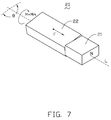
- FIGS. 4-7 are schematic views respectively showing the rotating process of the hinge assembly of FIG. 2 .
- FIG. 8 shows the magnetic force F measurement for the hinge assembly of FIG. 2 , wherein the y-axis indicates the magnetic force F, and the x-axis indicates the rotating angle ⁇ of the second magnetic member relative to the first magnetic member.
- FIG. 9 shows the magnetic moment M measurement for the hinge assembly of FIG. 2 , wherein the y-axis indicates the magnetic moment M, and the x-axis indicates the rotating angle ⁇ of the second magnetic member relative to the first magnetic member.
- FIGS. 10-12 are schematic views respectively showing the portable electronic device of FIG. 1 in a closed, dynamic balance, and opened position.
- FIG. 1 shows a portable electronic device 100 according to an exemplary embodiment.
- the cellular phone is taken here as an exemplary application for the purposes of describing details of the hinge assembly of the preferred embodiment.
- the cellular phone could be replaced by another portable electronic device, for example a personal digital assistant (PDA).
- PDA personal digital assistant
- the portable electronic device 100 has a conventional hinge assembly 20 to positively connect a cover 40 to a body 30 .
- the invention concerns the replacement of a conventional spring portion of the hinge with a magnetic structure.
- FIG. 2 shows a partial exploded isometric view of the present hinge assembly 20 .
- the hinge assembly 20 includes a first magnetic member 21 and a second magnetic member 22 .
- the first magnetic member 21 is substantially rectangular shaped and includes a first end surface 211 and a second end surface 212 opposite to the first end surface 211 .
- the first end surface 211 is a south (S) magnetic pole
- the second end surface 212 is a north (N) magnetic pole.
- the polarities of the first end surface 211 and the second end surface 212 can be exchanged.
- the second magnetic member 22 is also substantially rectangular shaped and includes a first end surface 221 and a second end surface 222 opposite to the first end surface 221 .
- the first end surface 221 is a north (N) magnetic pole
- the second end surface 222 is a south (S) magnetic pole.
- the polarities of the first end surface 221 and the second end surface 222 can be exchanged.
- the polarities of the adjacent end surfaces 211 , 221 of the first magnetic member 21 and the second magnetic member 22 should be opposite.
- the dimension of the end surfaces 211 , 221 of the first magnetic member 21 and the second magnetic member 22 are substantially equivalent to each other.
- the first end surface 221 of the second magnetic member 22 and the first end surface 211 of the first magnetic member 21 have opposite polarities so that the first and second magnetic members 21 , 22 are attracted/attached to each other due to magnetism therebetween.
- the hinge assembly 20 may be referred to as being in an “entirely attached state”.
- the magnetism applied to the second magnetic member 22 by the first magnetic member 21 includes a magnetic force F parallel to an axis L and a magnetic moment M for rotating the second magnetic member 22 relative to the first magnetic member 21 .
- FIGS. 8 and 9 respectively show the variation of the magnetic force F and the magnetic moment M between the first magnetic member 21 and the second magnetic member 22 .
- the x-axis of FIGS. 8 and 9 refer to a rotating angle ⁇ of the second magnetic member 22 relative to the first magnetic member 21 (hereinafter referred to as “the rotating angle ⁇ ”).
- the y-axis of FIGS. 8 and 9 respectively indicate the variation of the magnetic force F and the magnetic moment M.
- FIG. 3 shows the hinge assembly 20 in the entirely attached state, which means the rotating angle ⁇ is zero. Also referring to FIGS. 8 and 9 , the magnetic force F reaches its maximum, i.e., F m when the hinge assembly 20 is in the entirely attached state, and the magnetic moment M reaches its minimum, i.e., M 0 when the rotating angle ⁇ equals to 90 degrees.
- FIGS. 4 through 7 show the rotation of the second magnetic member 22 in a clockwise direction by an external force.
- the magnetic force F matingly attaches the second magnetic member 22 to the first magnetic member 21 .
- the magnetic force F gradually decreases, and the magnetic force F reaches its minimum F 0 when the angle ⁇ equals to 90 degrees as shown in FIG. 5 .
- the second magnetic member 22 is further rotated by external force as shown in FIGS. 6 and 7 until the angle ⁇ equals to 180 degrees.
- the magnetic force F gradually increases until reaching its maximum F m when the angle ⁇ equals to 180 degrees.
- the magnetic moment M is in a counterclockwise direction.
- the variation of the magnetic moment M is different from that of the magnetic force F.
- the magnetic moment M is at a minimum M 0 , i.e. zero.
- the magnetic moment M abruptly reaches its maximum M m at the beginning of the rotating process as shown in FIG. 4 .
- the second magnetic member 22 further rotates until the angle ⁇ equals to 90 degree as shown in FIG. 5 .
- the magnetic moment M gradually decreases.
- FIG. 9 when the angle ⁇ equals to 90 degree and the magnetic moment M equals to zero, the hinge assembly 20 is in a dynamical balance state. That is to say, the second magnetic member 22 is in a motionless state.
- the second magnetic member 22 is further rotated by external force and thus the magnetic moment M gradually increases.
- the magnetic moment M changes into a clockwise direction, which is in a same direction with the rotating direction of second magnetic member 22 , so that the magnetic moment M is shown with minus ( ⁇ ) sign as shown in FIG. 9 .
- the minus ( ⁇ ) as shown in FIG. 9 indicates change of direction of the magnetic moment M.
- the second magnetic member 22 automatically rotates as shown in FIG. 7 until the second end surface is entirely attached to the first end surface 211 of the first magnetic member 21 .
- the magnetic moment M again reaches its maximum M m .
- the magnetic moment M abruptly reaches its minimum M 0 when the angle ⁇ equals to 180 degree.
- the body 30 is a substantially rectangular board including a plurality of keys 31 arranged thereon.
- the body 30 includes a first hinge receiving portion 32 arranged in one side of the body 30 .
- the first hinge receiving portion 32 has an inner surface 34 with a substantially rectangular-shaped first receiving slot 35 and an exterior surface 33 opposite to the inner surface 34 .
- the dimension of the first receiving slot 35 is substantially equivalent to that of the first magnetic member 21 so that the first magnetic member 21 can be received in the first receiving slot 35 .
- the cover 40 is substantially a rectangular board including a display 41 (referring to FIG. 11 ) arranged thereon and a second hinge receiving portion 42 arranged in one side of the cover 40 in accordance with the first hinge receiving portion 32 of the body 30 .
- the second hinge receiving portion 42 has a substantially cylindrical-shaped inner surface 44 and an exterior surface 43 opposite to the inner surface 44 .
- the inner surface 44 of the second hinge receiving portion 42 defines a substantially rectangular-shaped second receiving slot 45 .
- the dimension of the second receiving slot 45 is substantially equivalent to that of the second magnetic member 22 so that the second magnetic member 22 can be received in the second hinge receiving portion 42 .
- the south (S) magnetic pole of the first magnetic member 21 is configured to be arranged adjacent to the inner surface 34 of the first hinge receiving portion 32 of the body 30
- the north (N) magnetic pole of the second magnetic member 22 is adjacent to the inner surface 44 of the second hinge receiving portion 42 of the cover 40
- the inner surface 44 of the second hinge receiving portion 42 of the cover 40 faces the inner surface 34 of the first hinge receiving portion 32 of the body 30 .
- the hinge assembly 20 is in the entirely attached state, namely, the first end surface 221 of the second magnetic member 22 is entirely attached to the first end surface 211 of the first magnetic member 21 .
- the second magnetic member 22 rotates in a counter-clockwise direction relative to the first magnetic member 21 until the cover 40 is perpendicular to the body 30 .
- the magnetic moment M is zero, and the cover 40 is in a dynamical balance state relative to the body 30 as shown in FIG. 11 .
- the magnetic moment M applied to the hinge assembly 20 changes oppositely, namely, the magnetic moment M applied to the hinge assembly 20 is in the counter-clockwise direction.
- the cover 30 will be automatically continuously rotated in the counter-clockwise direction to a full closed position as shown in FIG. 10 due to the magnetic moment M.
- the south (S) magnetic pole of the first magnetic member 21 can be located to be adjacent to the exterior surface 33 of the first hinge receiving portion 32 .
- the north (N) magnetic pole of the second magnetic member 22 can be located to be adjacent to the exterior surface 43 of the second hinge receiving portion 42 .
- the shapes of the end surfaces of the first magnetic member 21 and the second magnetic member 22 can also be in other shapes.
- the magnetic force F and the magnetic moment M are generated only if the angle ⁇ of the second magnetic member 22 relative to the first magnetic member 21 is greater than zero.
- the present hinge assembly 20 makes use of the generated magnetic moment M when the end surfaces 211 , 221 of the first magnetic member 21 and the second magnetic member 22 are not entirely attached to each other to unfold the cover 40 of the portable electronic device 100 .
- the structure of the hinge assembly 20 is simple, and the cost is low. Further, the process of assembling the hinge assembly 20 to the portable electronic device 100 can be achieved easily without utilizing additional fixtures.
- the hinge assembly 20 may be applied in various portable devices, beyond the cellular phone illustrated, and/or with other devices needing a hinge assembly 20 that selectably facilitates the achievement of fully open and fully closed positions.
Landscapes
- Engineering & Computer Science (AREA)
- Signal Processing (AREA)
- Telephone Set Structure (AREA)
Abstract
Description
Claims (12)
Applications Claiming Priority (3)
| Application Number | Priority Date | Filing Date | Title |
|---|---|---|---|
| CN2007102035594A CN101469735B (en) | 2007-12-29 | 2007-12-29 | Hinge mechanism and portable electronic device equipped therewith |
| CN200710203559 | 2007-12-29 | ||
| CN200710203559.4 | 2007-12-29 |
Publications (2)
| Publication Number | Publication Date |
|---|---|
| US20090167472A1 US20090167472A1 (en) | 2009-07-02 |
| US7915986B2 true US7915986B2 (en) | 2011-03-29 |
Family
ID=40797498
Family Applications (1)
| Application Number | Title | Priority Date | Filing Date |
|---|---|---|---|
| US12/133,526 Expired - Fee Related US7915986B2 (en) | 2007-12-29 | 2008-06-05 | Hinge assembly and portable electronic devices using same |
Country Status (2)
| Country | Link |
|---|---|
| US (1) | US7915986B2 (en) |
| CN (1) | CN101469735B (en) |
Cited By (19)
| Publication number | Priority date | Publication date | Assignee | Title |
|---|---|---|---|---|
| US20110122594A1 (en) * | 2009-11-20 | 2011-05-26 | Jason Tyler Griffin | Magnetic hinge electronic mobile device |
| US8138869B1 (en) * | 2010-09-17 | 2012-03-20 | Apple Inc. | Accessory device with magnetic attachment |
| US20120066873A1 (en) * | 2010-09-17 | 2012-03-22 | Apple Inc. | Methods and apparatus for configuring a magnetic attachment system |
| US8143983B1 (en) * | 2010-09-17 | 2012-03-27 | Apple Inc. | Electronic device with magnetic attachment |
| US8143982B1 (en) | 2010-09-17 | 2012-03-27 | Apple Inc. | Foldable accessory device |
| US8253518B2 (en) | 2010-09-17 | 2012-08-28 | Apple Inc. | Foldable cover for electronic device |
| US8289115B2 (en) | 2010-09-17 | 2012-10-16 | Apple Inc. | Sensor fusion |
| US8344836B2 (en) | 2010-09-17 | 2013-01-01 | Apple Inc. | Protective cover for a tablet computer |
| US8390411B2 (en) | 2010-09-17 | 2013-03-05 | Apple Inc. | Tablet device |
| US8395465B2 (en) | 2010-09-17 | 2013-03-12 | Apple Inc. | Cover for an electric device |
| US8737668B1 (en) | 2013-01-23 | 2014-05-27 | Koss Corporation | Headband for personal speakers |
| US8752249B1 (en) * | 2013-02-01 | 2014-06-17 | Jarllytec Co., Ltd. | Pivotal shaft device |
| US20140230191A1 (en) * | 2013-02-18 | 2014-08-21 | Elesa S.P.A. | Hinge having an embedded safety switch |
| US8861770B2 (en) | 2013-01-23 | 2014-10-14 | Koss Corporation | Headband for personal speakers |
| US8899636B2 (en) | 2011-12-22 | 2014-12-02 | Eaton Corporation | Magnetic latch |
| US9324487B1 (en) * | 2014-06-11 | 2016-04-26 | Amazon Technologies, Inc. | Damper for magnetic coupler |
| US20170352459A1 (en) * | 2016-06-06 | 2017-12-07 | Apple Inc. | Magnetic Materials Polarized at an Oblique Angle |
| CN110130759A (en) * | 2019-04-22 | 2019-08-16 | 江苏银奕达科技股份有限公司 | A kind of built-in anti-sway aluminium profile structure pushing and pulling sliding door, window |
| US10503216B2 (en) | 2014-03-28 | 2019-12-10 | Intel Corporation | Adjustment of magnetic force in a computing device |
Families Citing this family (16)
| Publication number | Priority date | Publication date | Assignee | Title |
|---|---|---|---|---|
| CN101672322B (en) * | 2008-09-10 | 2012-06-20 | 鸿富锦精密工业(深圳)有限公司 | Magnetic hinge structure |
| CN101684840B (en) * | 2008-09-25 | 2012-10-10 | 鸿富锦精密工业(深圳)有限公司 | Magnetic hinge structure |
| ATE540521T1 (en) * | 2009-11-20 | 2012-01-15 | Research In Motion Ltd | MAGNETIC ELECTRONIC MOBILE HINGE DEVICE |
| EP2672163A1 (en) * | 2012-06-06 | 2013-12-11 | BlackBerry Limited | Electronic device support with magnetic indexing |
| US8780549B2 (en) | 2012-06-06 | 2014-07-15 | Blackberry Limited | Electronic device support with magnetic indexing |
| TWI495987B (en) * | 2013-06-25 | 2015-08-11 | Wistron Corp | Hinge and foldable electronic apparatus |
| EP3145381A4 (en) * | 2014-05-22 | 2018-04-04 | Nilfisk A/S | A cleaning machine, such as a vacuum cleaner comprising a housing, and a hingeable element being detachably attachable thereto |
| RU168229U1 (en) * | 2016-10-04 | 2017-01-24 | Вячеслав Сергеевич Перфильев | Door hinge |
| CN107989889B (en) * | 2017-10-30 | 2020-10-30 | 浙江峰邦机械科技有限公司 | Detachable magnetic hinge structure |
| CN107956788A (en) * | 2017-12-27 | 2018-04-24 | 浙江工业大学 | Magnetic hinge |
| US10912213B2 (en) * | 2017-12-27 | 2021-02-02 | Lg Display Co., Ltd. | Foldable display device maintaining a folding angle by magnetic force |
| CN108712548B (en) * | 2018-05-18 | 2020-07-17 | 常州信息职业技术学院 | Communication equipment |
| CN108737602B (en) * | 2018-05-18 | 2020-07-17 | 常州信息职业技术学院 | Mobile communication terminal |
| CN111781991B (en) * | 2020-06-17 | 2022-04-22 | 维沃移动通信有限公司 | Hinge and electronic equipment |
| US11876407B2 (en) * | 2020-07-31 | 2024-01-16 | Lenovo (Singapore) Pte. Ltd. | Assembly for rotary motion using electropermanent magnet assembly |
| CN215058838U (en) * | 2020-12-09 | 2021-12-07 | 杭州安费诺飞凤通信部品有限公司 | Double-shaft synchronous hinge |
Citations (14)
| Publication number | Priority date | Publication date | Assignee | Title |
|---|---|---|---|---|
| US20020119802A1 (en) * | 2001-02-28 | 2002-08-29 | Nec Corporation | Portable cellular phone |
| US20020147026A1 (en) * | 2001-04-04 | 2002-10-10 | Yung-Tsun Hsieh | Magnetic hinge apparatus |
| CN1382893A (en) | 2001-04-26 | 2002-12-04 | 明碁电通股份有限公司 | Magnetic hinge unit |
| US20030179880A1 (en) * | 2002-03-20 | 2003-09-25 | Long-Jyh Pan | Magnetic hinge apparatus |
| US20030178901A1 (en) * | 2002-03-25 | 2003-09-25 | Clarity, Llc | Electromagnetic positioning |
| US6630878B2 (en) * | 2002-03-08 | 2003-10-07 | Benq Corporation | Magnetic rotating apparatus |
| US20050136970A1 (en) * | 2003-12-22 | 2005-06-23 | Lg Electronics Inc. | Swivel-type mobile terminal and control method thereof |
| US20050194384A1 (en) * | 2002-09-06 | 2005-09-08 | Robert Petit | Packaging, typically a case, with closure by magnets |
| US20050208984A1 (en) * | 2004-03-22 | 2005-09-22 | Benq Corporation | Unfolding device and mobile phone utilizing the same |
| US7074045B2 (en) * | 2003-07-22 | 2006-07-11 | Fujitsu Limited | Portable terminal device and open/close detector |
| US20060214756A1 (en) * | 2005-03-25 | 2006-09-28 | Ellihay Corp. | Levitation of objects using magnetic force |
| US20070077971A1 (en) * | 2005-09-30 | 2007-04-05 | Fih Co., Ltd | Hinge assembly for a foldable electronic device |
| US20070077972A1 (en) * | 2005-09-30 | 2007-04-05 | Fih Co., Ltd | Hinge assembly for a foldable electronic device |
| US7288934B1 (en) * | 2006-09-07 | 2007-10-30 | Alps Electric Co., Ltd. | Electronic device incorporating magnetoresistive elements for sensing both N and S magnetic poles |
Family Cites Families (1)
| Publication number | Priority date | Publication date | Assignee | Title |
|---|---|---|---|---|
| CN2750110Y (en) * | 2004-12-03 | 2006-01-04 | 深圳富泰宏精密工业有限公司 | Hinge structure |
-
2007
- 2007-12-29 CN CN2007102035594A patent/CN101469735B/en not_active Expired - Fee Related
-
2008
- 2008-06-05 US US12/133,526 patent/US7915986B2/en not_active Expired - Fee Related
Patent Citations (14)
| Publication number | Priority date | Publication date | Assignee | Title |
|---|---|---|---|---|
| US20020119802A1 (en) * | 2001-02-28 | 2002-08-29 | Nec Corporation | Portable cellular phone |
| US20020147026A1 (en) * | 2001-04-04 | 2002-10-10 | Yung-Tsun Hsieh | Magnetic hinge apparatus |
| CN1382893A (en) | 2001-04-26 | 2002-12-04 | 明碁电通股份有限公司 | Magnetic hinge unit |
| US6630878B2 (en) * | 2002-03-08 | 2003-10-07 | Benq Corporation | Magnetic rotating apparatus |
| US20030179880A1 (en) * | 2002-03-20 | 2003-09-25 | Long-Jyh Pan | Magnetic hinge apparatus |
| US20030178901A1 (en) * | 2002-03-25 | 2003-09-25 | Clarity, Llc | Electromagnetic positioning |
| US20050194384A1 (en) * | 2002-09-06 | 2005-09-08 | Robert Petit | Packaging, typically a case, with closure by magnets |
| US7074045B2 (en) * | 2003-07-22 | 2006-07-11 | Fujitsu Limited | Portable terminal device and open/close detector |
| US20050136970A1 (en) * | 2003-12-22 | 2005-06-23 | Lg Electronics Inc. | Swivel-type mobile terminal and control method thereof |
| US20050208984A1 (en) * | 2004-03-22 | 2005-09-22 | Benq Corporation | Unfolding device and mobile phone utilizing the same |
| US20060214756A1 (en) * | 2005-03-25 | 2006-09-28 | Ellihay Corp. | Levitation of objects using magnetic force |
| US20070077971A1 (en) * | 2005-09-30 | 2007-04-05 | Fih Co., Ltd | Hinge assembly for a foldable electronic device |
| US20070077972A1 (en) * | 2005-09-30 | 2007-04-05 | Fih Co., Ltd | Hinge assembly for a foldable electronic device |
| US7288934B1 (en) * | 2006-09-07 | 2007-10-30 | Alps Electric Co., Ltd. | Electronic device incorporating magnetoresistive elements for sensing both N and S magnetic poles |
Cited By (36)
| Publication number | Priority date | Publication date | Assignee | Title |
|---|---|---|---|---|
| US8159834B2 (en) * | 2009-11-20 | 2012-04-17 | Research In Motion Ltd. | Magnetic hinge electronic mobile device |
| US20110122594A1 (en) * | 2009-11-20 | 2011-05-26 | Jason Tyler Griffin | Magnetic hinge electronic mobile device |
| US8861224B2 (en) | 2009-11-20 | 2014-10-14 | Blackberry Limited | Magnetic hinge electronic mobile device |
| US9568954B2 (en) | 2010-09-17 | 2017-02-14 | Apple Inc. | Cover for an electronic device |
| US8289115B2 (en) | 2010-09-17 | 2012-10-16 | Apple Inc. | Sensor fusion |
| US8143982B1 (en) | 2010-09-17 | 2012-03-27 | Apple Inc. | Foldable accessory device |
| US10580556B2 (en) | 2010-09-17 | 2020-03-03 | Apple Inc. | Cover for an electronic device |
| US8242868B2 (en) * | 2010-09-17 | 2012-08-14 | Apple Inc. | Methods and apparatus for configuring a magnetic attachment system |
| US8253518B2 (en) | 2010-09-17 | 2012-08-28 | Apple Inc. | Foldable cover for electronic device |
| US8264310B2 (en) | 2010-09-17 | 2012-09-11 | Apple Inc. | Accessory device for peek mode |
| US10236106B2 (en) | 2010-09-17 | 2019-03-19 | Apple Inc. | Cover for an electronic device |
| US8344836B2 (en) | 2010-09-17 | 2013-01-01 | Apple Inc. | Protective cover for a tablet computer |
| US8390412B2 (en) | 2010-09-17 | 2013-03-05 | Apple Inc. | Protective cover |
| US8390411B2 (en) | 2010-09-17 | 2013-03-05 | Apple Inc. | Tablet device |
| US8395465B2 (en) | 2010-09-17 | 2013-03-12 | Apple Inc. | Cover for an electric device |
| US8514042B2 (en) * | 2010-09-17 | 2013-08-20 | Apple Inc. | Magnetic attachment system |
| US9773598B2 (en) | 2010-09-17 | 2017-09-26 | Apple Inc. | Cover for an electronic device |
| US8624695B2 (en) | 2010-09-17 | 2014-01-07 | Apple Inc. | Sensor fusion |
| US8138869B1 (en) * | 2010-09-17 | 2012-03-20 | Apple Inc. | Accessory device with magnetic attachment |
| US20120068799A1 (en) * | 2010-09-17 | 2012-03-22 | Apple Inc. | Accessory device with magnetic attachment |
| US8143983B1 (en) * | 2010-09-17 | 2012-03-27 | Apple Inc. | Electronic device with magnetic attachment |
| US8576031B2 (en) | 2010-09-17 | 2013-11-05 | Apple Inc. | Consumer product system |
| US20120066873A1 (en) * | 2010-09-17 | 2012-03-22 | Apple Inc. | Methods and apparatus for configuring a magnetic attachment system |
| US9329630B2 (en) | 2010-09-17 | 2016-05-03 | Apple Inc. | Cover |
| US8899636B2 (en) | 2011-12-22 | 2014-12-02 | Eaton Corporation | Magnetic latch |
| US8737668B1 (en) | 2013-01-23 | 2014-05-27 | Koss Corporation | Headband for personal speakers |
| US8861770B2 (en) | 2013-01-23 | 2014-10-14 | Koss Corporation | Headband for personal speakers |
| US8752249B1 (en) * | 2013-02-01 | 2014-06-17 | Jarllytec Co., Ltd. | Pivotal shaft device |
| US8966714B2 (en) * | 2013-02-18 | 2015-03-03 | Elesa S.P.A. | Hinge having an embedded safety switch |
| US20140230191A1 (en) * | 2013-02-18 | 2014-08-21 | Elesa S.P.A. | Hinge having an embedded safety switch |
| US10503216B2 (en) | 2014-03-28 | 2019-12-10 | Intel Corporation | Adjustment of magnetic force in a computing device |
| US11106250B2 (en) | 2014-03-28 | 2021-08-31 | Intel Corporation | Adjustment of magnetic force in a computing device |
| US9324487B1 (en) * | 2014-06-11 | 2016-04-26 | Amazon Technologies, Inc. | Damper for magnetic coupler |
| US20170352459A1 (en) * | 2016-06-06 | 2017-12-07 | Apple Inc. | Magnetic Materials Polarized at an Oblique Angle |
| US10074469B2 (en) * | 2016-06-06 | 2018-09-11 | Apple Inc. | Magnetic materials polarized at an oblique angle |
| CN110130759A (en) * | 2019-04-22 | 2019-08-16 | 江苏银奕达科技股份有限公司 | A kind of built-in anti-sway aluminium profile structure pushing and pulling sliding door, window |
Also Published As
| Publication number | Publication date |
|---|---|
| US20090167472A1 (en) | 2009-07-02 |
| CN101469735B (en) | 2011-06-29 |
| CN101469735A (en) | 2009-07-01 |
Similar Documents
| Publication | Publication Date | Title |
|---|---|---|
| US7915986B2 (en) | Hinge assembly and portable electronic devices using same | |
| US20030179880A1 (en) | Magnetic hinge apparatus | |
| US8869352B2 (en) | Multi-segment rotary shaft structure | |
| US9069531B2 (en) | Portable device and mobile phone with double hinge torsion bar | |
| US8240007B2 (en) | Hinge assembly for foldable electronic device | |
| US8451601B2 (en) | Double hinge axial cams | |
| US8159834B2 (en) | Magnetic hinge electronic mobile device | |
| US8248788B2 (en) | Tilt mechanism for electronic device | |
| US20120162866A1 (en) | Double Hinge Radial Cams | |
| US7924554B2 (en) | Electronic device having movable display | |
| US20070077972A1 (en) | Hinge assembly for a foldable electronic device | |
| WO2021143500A1 (en) | Foldable mobile terminal | |
| US20100162526A1 (en) | Hinge assembly for foldable electronic device | |
| US6630878B2 (en) | Magnetic rotating apparatus | |
| US9570866B2 (en) | Jack assembly and portable electronic device with same | |
| US8233276B2 (en) | Tilt mechanism for electronic device | |
| US20090058578A1 (en) | Portable electronic device with hall sensor | |
| US8248787B2 (en) | Portable electronic device with slidable cover | |
| US7404235B2 (en) | Hinge assembly for portable electronic devices | |
| US20070077971A1 (en) | Hinge assembly for a foldable electronic device | |
| US8422204B2 (en) | Slide electronic device | |
| US20120162926A1 (en) | Sliding module for electronic device | |
| KR100616224B1 (en) | Mobile communication terminal having swing hinge using magnetics | |
| EP2326064B1 (en) | Magnetic hinge electronic mobile device | |
| TWI399478B (en) | Hinge and portable electronic device using same |
Legal Events
| Date | Code | Title | Description |
|---|---|---|---|
| AS | Assignment |
Owner name: CHI MEI COMMUNICATION SYSTEMS, INC., TAIWAN Free format text: ASSIGNMENT OF ASSIGNORS INTEREST;ASSIGNOR:LU, PEN-UEI;REEL/FRAME:021051/0412 Effective date: 20080528 |
|
| STCF | Information on status: patent grant |
Free format text: PATENTED CASE |
|
| FPAY | Fee payment |
Year of fee payment: 4 |
|
| FEPP | Fee payment procedure |
Free format text: MAINTENANCE FEE REMINDER MAILED (ORIGINAL EVENT CODE: REM.); ENTITY STATUS OF PATENT OWNER: LARGE ENTITY |
|
| LAPS | Lapse for failure to pay maintenance fees |
Free format text: PATENT EXPIRED FOR FAILURE TO PAY MAINTENANCE FEES (ORIGINAL EVENT CODE: EXP.); ENTITY STATUS OF PATENT OWNER: LARGE ENTITY |
|
| STCH | Information on status: patent discontinuation |
Free format text: PATENT EXPIRED DUE TO NONPAYMENT OF MAINTENANCE FEES UNDER 37 CFR 1.362 |
|
| FP | Lapsed due to failure to pay maintenance fee |
Effective date: 20190329 |