US7841831B2 - Asymmetrically changing rotating blade shape (ACRBS) propeller and its airplane and wind turbine applications - Google Patents
Asymmetrically changing rotating blade shape (ACRBS) propeller and its airplane and wind turbine applications Download PDFInfo
- Publication number
- US7841831B2 US7841831B2 US11/592,851 US59285106A US7841831B2 US 7841831 B2 US7841831 B2 US 7841831B2 US 59285106 A US59285106 A US 59285106A US 7841831 B2 US7841831 B2 US 7841831B2
- Authority
- US
- United States
- Prior art keywords
- blade
- propeller
- pair
- rotation
- blades
- Prior art date
- Legal status (The legal status is an assumption and is not a legal conclusion. Google has not performed a legal analysis and makes no representation as to the accuracy of the status listed.)
- Expired - Fee Related, expires
Links
- 230000001419 dependent effect Effects 0.000 claims abstract description 8
- 239000012530 fluid Substances 0.000 claims description 14
- XLYOFNOQVPJJNP-UHFFFAOYSA-N water Substances O XLYOFNOQVPJJNP-UHFFFAOYSA-N 0.000 claims description 11
- 238000000034 method Methods 0.000 claims description 7
- 238000013459 approach Methods 0.000 claims description 2
- 230000007246 mechanism Effects 0.000 description 22
- 239000013598 vector Substances 0.000 description 11
- 230000008859 change Effects 0.000 description 8
- 230000009471 action Effects 0.000 description 4
- 238000010586 diagram Methods 0.000 description 3
- 239000000463 material Substances 0.000 description 3
- 230000008901 benefit Effects 0.000 description 2
- 230000005540 biological transmission Effects 0.000 description 2
- 230000001681 protective effect Effects 0.000 description 2
- 238000003466 welding Methods 0.000 description 2
- 241000238631 Hexapoda Species 0.000 description 1
- 238000010521 absorption reaction Methods 0.000 description 1
- 230000003466 anti-cipated effect Effects 0.000 description 1
- 238000006243 chemical reaction Methods 0.000 description 1
- 238000010276 construction Methods 0.000 description 1
- 230000007423 decrease Effects 0.000 description 1
- 230000003247 decreasing effect Effects 0.000 description 1
- 230000001934 delay Effects 0.000 description 1
- 238000006073 displacement reaction Methods 0.000 description 1
- 230000000694 effects Effects 0.000 description 1
- 230000005611 electricity Effects 0.000 description 1
- 238000003306 harvesting Methods 0.000 description 1
- 239000002184 metal Substances 0.000 description 1
- 230000004044 response Effects 0.000 description 1
Images


Classifications
-
- B—PERFORMING OPERATIONS; TRANSPORTING
- B64—AIRCRAFT; AVIATION; COSMONAUTICS
- B64C—AEROPLANES; HELICOPTERS
- B64C11/00—Propellers, e.g. of ducted type; Features common to propellers and rotors for rotorcraft
-
- B—PERFORMING OPERATIONS; TRANSPORTING
- B63—SHIPS OR OTHER WATERBORNE VESSELS; RELATED EQUIPMENT
- B63H—MARINE PROPULSION OR STEERING
- B63H3/00—Propeller-blade pitch changing
-
- B—PERFORMING OPERATIONS; TRANSPORTING
- B64—AIRCRAFT; AVIATION; COSMONAUTICS
- B64C—AEROPLANES; HELICOPTERS
- B64C11/00—Propellers, e.g. of ducted type; Features common to propellers and rotors for rotorcraft
- B64C11/30—Blade pitch-changing mechanisms
-
- B—PERFORMING OPERATIONS; TRANSPORTING
- B64—AIRCRAFT; AVIATION; COSMONAUTICS
- B64C—AEROPLANES; HELICOPTERS
- B64C27/00—Rotorcraft; Rotors peculiar thereto
- B64C27/54—Mechanisms for controlling blade adjustment or movement relative to rotor head, e.g. lag-lead movement
- B64C27/58—Transmitting means, e.g. interrelated with initiating means or means acting on blades
- B64C27/59—Transmitting means, e.g. interrelated with initiating means or means acting on blades mechanical
-
- F—MECHANICAL ENGINEERING; LIGHTING; HEATING; WEAPONS; BLASTING
- F03—MACHINES OR ENGINES FOR LIQUIDS; WIND, SPRING, OR WEIGHT MOTORS; PRODUCING MECHANICAL POWER OR A REACTIVE PROPULSIVE THRUST, NOT OTHERWISE PROVIDED FOR
- F03D—WIND MOTORS
- F03D3/00—Wind motors with rotation axis substantially perpendicular to the air flow entering the rotor
- F03D3/06—Rotors
- F03D3/062—Rotors characterised by their construction elements
- F03D3/066—Rotors characterised by their construction elements the wind engaging parts being movable relative to the rotor
- F03D3/067—Cyclic movements
- F03D3/068—Cyclic movements mechanically controlled by the rotor structure
-
- F—MECHANICAL ENGINEERING; LIGHTING; HEATING; WEAPONS; BLASTING
- F04—POSITIVE - DISPLACEMENT MACHINES FOR LIQUIDS; PUMPS FOR LIQUIDS OR ELASTIC FLUIDS
- F04D—NON-POSITIVE-DISPLACEMENT PUMPS
- F04D29/00—Details, component parts, or accessories
- F04D29/26—Rotors specially for elastic fluids
- F04D29/28—Rotors specially for elastic fluids for centrifugal or helico-centrifugal pumps for radial-flow or helico-centrifugal pumps
- F04D29/281—Rotors specially for elastic fluids for centrifugal or helico-centrifugal pumps for radial-flow or helico-centrifugal pumps for fans or blowers
-
- F—MECHANICAL ENGINEERING; LIGHTING; HEATING; WEAPONS; BLASTING
- F05—INDEXING SCHEMES RELATING TO ENGINES OR PUMPS IN VARIOUS SUBCLASSES OF CLASSES F01-F04
- F05B—INDEXING SCHEME RELATING TO WIND, SPRING, WEIGHT, INERTIA OR LIKE MOTORS, TO MACHINES OR ENGINES FOR LIQUIDS COVERED BY SUBCLASSES F03B, F03D AND F03G
- F05B2240/00—Components
- F05B2240/20—Rotors
- F05B2240/21—Rotors for wind turbines
- F05B2240/211—Rotors for wind turbines with vertical axis
- F05B2240/218—Rotors for wind turbines with vertical axis with horizontally hinged vanes
-
- F—MECHANICAL ENGINEERING; LIGHTING; HEATING; WEAPONS; BLASTING
- F05—INDEXING SCHEMES RELATING TO ENGINES OR PUMPS IN VARIOUS SUBCLASSES OF CLASSES F01-F04
- F05B—INDEXING SCHEME RELATING TO WIND, SPRING, WEIGHT, INERTIA OR LIKE MOTORS, TO MACHINES OR ENGINES FOR LIQUIDS COVERED BY SUBCLASSES F03B, F03D AND F03G
- F05B2260/00—Function
- F05B2260/40—Transmission of power
- F05B2260/403—Transmission of power through the shape of the drive components
- F05B2260/4031—Transmission of power through the shape of the drive components as in toothed gearing
-
- Y—GENERAL TAGGING OF NEW TECHNOLOGICAL DEVELOPMENTS; GENERAL TAGGING OF CROSS-SECTIONAL TECHNOLOGIES SPANNING OVER SEVERAL SECTIONS OF THE IPC; TECHNICAL SUBJECTS COVERED BY FORMER USPC CROSS-REFERENCE ART COLLECTIONS [XRACs] AND DIGESTS
- Y02—TECHNOLOGIES OR APPLICATIONS FOR MITIGATION OR ADAPTATION AGAINST CLIMATE CHANGE
- Y02B—CLIMATE CHANGE MITIGATION TECHNOLOGIES RELATED TO BUILDINGS, e.g. HOUSING, HOUSE APPLIANCES OR RELATED END-USER APPLICATIONS
- Y02B10/00—Integration of renewable energy sources in buildings
- Y02B10/30—Wind power
-
- Y—GENERAL TAGGING OF NEW TECHNOLOGICAL DEVELOPMENTS; GENERAL TAGGING OF CROSS-SECTIONAL TECHNOLOGIES SPANNING OVER SEVERAL SECTIONS OF THE IPC; TECHNICAL SUBJECTS COVERED BY FORMER USPC CROSS-REFERENCE ART COLLECTIONS [XRACs] AND DIGESTS
- Y02—TECHNOLOGIES OR APPLICATIONS FOR MITIGATION OR ADAPTATION AGAINST CLIMATE CHANGE
- Y02E—REDUCTION OF GREENHOUSE GAS [GHG] EMISSIONS, RELATED TO ENERGY GENERATION, TRANSMISSION OR DISTRIBUTION
- Y02E10/00—Energy generation through renewable energy sources
- Y02E10/70—Wind energy
- Y02E10/74—Wind turbines with rotation axis perpendicular to the wind direction
Definitions
- the present disclosure relates to an asymmetrically changing rotating propeller and, more specifically, to an asymmetrically changing rotating blade shape propeller and its airplane and wind turbine applications.
- a propeller is a device which forces fluid passing through it and increases the fluid kinetic energy.
- Vehicles or vessels such as airplanes, ships and submarines may use propellers to propel though a fluid such as air or water.
- a propeller can be placed in the path of a moving fluid to absorb the fluid kinetic energy, such as a wind mill.
- a typical propeller is generally comprised of one or more twisted blades which are rotated around a central shaft.
- While conventional propellers provide symmetric thrust with respect to each revolution cycle, examples of asymmetric propulsion techniques are known.
- a boater sweeps an oar from front to back while its face is submerged in water and then, to complete the rowing cycle, the boater carries the oar to its original front position while removed from the water.
- the boater By moving the oar from the more dense water to the less dense air on the return stroke, the boater is able to apply maximum energy during the front-to-back sweep and conserve energy on the return thereby maximizing propulsion efficiency.
- the angle of the oar may also be adjusted by the boater to further optimize propulsion efficiency
- Another example is when a swimmer performs the breast-stroke.
- a swimmer's arms are swept from front-to-back while under the water and are then returned to their original front position while removed from the water.
- the angle of the swimmer's hands may also be adjusted to optimize the propulsion efficiency.
- variable pitch propellers have the ability to alter blade lift and drag coefficients
- lift and drag are not changed during the course of the propeller's rotational cycle.
- Another example involved the wing flapping of a bird or an insect.
- the wing pushes the air downward/backward of the bird. This increases downward/backward air momentum passing through the wing.
- the reaction to this air momentum increase is a force which pushes the bird upward/forward.
- the wing must return to its starting cycle configuration in order to be ready for its next wing-flapping cycle. This is done during the second half of the wing-flapping cycle.
- Most wings are not designed to produce desired thrust in both half cycles. Therefore, the wing must conserve its energy to perform its second half cycle return journey.
- a propeller have the ability to adjust the drag coefficient of each blade during the course of the propeller's rotational cycle.
- a propeller includes a plurality of propeller blades. Each blade has an adjustable drag coefficient.
- a plurality of actuators adjusts the drag coefficients of the propeller blades.
- a controlling unit controls the plurality of actuators such that the drag coefficient of each propeller blade is adjusted according to a pattern that is dependent upon the rotational angle of the particular propeller blade.
- a method for propelling a vehicle or vessel though a fluid includes rotating a propeller having one or more blades.
- the drag of each of the one or more blades is adjusted according to a pattern that is dependent upon the rotational angle of the particular propeller blade.
- a method for harvesting wind energy with a wind turbine includes configuring one or more propellers with one or more blades to be rotated by the force of wind.
- the drag of each of the one or more blades is adjusted according to a pattern that is dependent upon the rotational angle of the particular propeller blade, relative to the incoming air velocity.
- FIG. 1 is a perspective view of an example propeller according to an embodiment of the present invention
- FIG. 2A is a graph showing an example of how the opening angle of the propeller blades may change as a function of the angle of rotation;
- FIG. 2B is a graph showing an example of how the surface area (perpendicular to the incoming tangent velocity due to propeller rotation) of the propeller blades may change as a function of the angle of rotation;
- FIG. 2C is a graph showing an example of how the drag coefficient of the propeller blades may change as a function of the angle of rotation;
- FIG. 3 is a plan view showing four connecting members which may connect four blade-pairs of a propeller according to the present invention
- FIG. 4 is a side view of the four connecting members depicted in FIG. 3 ;
- FIG. 5A is a plan view of a first propeller blade of a blade-pair according to an embodiment of the present invention.
- FIG. 5B is a plan view of a second propeller blade of a blade pair according to an embodiment of the present invention.
- FIG. 5C is a side view of the propeller blade depicted in FIG. 5A ;
- FIG. 5D is a side view of the propeller blade depicted in FIG. 5B ;
- FIG. 6A is a plan view of a rotating disc with support tubes according to an embodiment of the present invention.
- FIG. 6B is a side view of the rotating disc with support tubes depicted in FIG. 6A ;
- FIG. 7A is a plan view of a cover according to an embodiment of the present invention.
- FIG. 7B is a side view of the cover depicted in FIG. 7A ;
- FIG. 8A is an exploded plan view of a control link and control mechanism according to an embodiment of the present invention.
- FIG. 8B is a side view of the control rod depicted in FIG. 8A ;
- FIG. 8C is a rear view of the control rod depicted in FIG. 8A ;
- FIG. 8D is a top view of the control rod depicted in FIG. 8A ;
- FIG. 9A is a plan view of a ring base according to an embodiment of the present invention.
- FIG. 9B is a side view of the ring base depicted in FIG. 9A ;
- FIG. 9C is another side view of the ring base depicted in FIG. 9A ;
- FIG. 9D is a diagram of the shape of the guide track throughout the course of a single revolution as a function of the angle of rotation;
- FIG. 10 is a partial side view of a propeller blade with actuating mechanism according to an embodiment of the present invention.
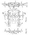
- FIG. 11A is a plan view showing the arrangement of four propellers on an airplane, according to an embodiment of the present invention.
- FIG. 11B is a side view of the airplane propeller arrangement depicted in FIG. 11A ;
- FIG. 11C is another side view of the airplane propeller arrangement depicted in FIG. 11A ;
- FIG. 12A is a front view of an airplane according to an embodiment of the present invention.
- FIG. 12B is a top view of the airplane depicted in FIG. 12A ;
- FIG. 12C is a side view of the airplane depicted in FIG. 12A ;
- FIG. 13 is a cross-sectional view of a windmill according to an embodiment of the present invention.
- a propeller according to embodiments of the present invention may include a plurality of propeller blades arranged in pairs.
- Each propeller blade-pair may have a set of two hinged blades that are capable of opening and closing at specific intervals in each cycle of revolution. When the blade-pairs are fully closed, the blades may be nearly flat. As the blade-pairs open, the blade becomes non-flat and the surface area of the blade-pairs, which is perpendicular to the incoming wind velocity vector, increases.
- Propellers according to embodiments of the present invention may have multiple blades. While the propeller may have any number of blades, examples described herein have four blade-pairs.
- all of the blade-pairs may have hinged blades.
- FIG. 1 is a planar view of an example propeller according to an embodiment of the present invention.
- the propeller 10 has four blade-pairs 20 , 21 , 22 , 23 that each consist of a first blade 1 a hingedly connected along a radial axis to a second blade 1 b .
- the details of the structure and connection of the blades will be described in more detail herein with reference to FIGS. 5A through 5D and FIG. 10 .
- the four blade-pairs 20 , 21 , 22 , 23 are further arranged in pairs of two 20 , 22 and 21 , 23 with each blade-pair being disposed 180 degrees from the other blade-pair in the pair, and each pair being 90 degrees displaced from the other pair, for example.
- the blade-pairs are interconnected with connecting members 4 a to form the propeller 10 .
- the propeller 10 rotates around a central axis 1 p , in a clockwise direction so that the opening of the blade-pairs faces the incoming tangential air velocity vector 1 v.
- the changing area of the propeller blades can best be understood with reference to the plane of rotation defined by the x- and y-axes depicted in FIG. 1 .
- the angle of rotation 1 e of any given blade-pair 20 , 21 , 22 , 23 is measured with respect to a predefined start point (0°), in this case chosen to coincide with the x-axis.
- the angle of the opening 1 f between the blades 1 a , 1 b of each blade-pair 20 , 21 , 22 , 23 changes throughout one cycle of rotation (360°) from a maximum at angle of rotation of 0° (i.e.
- the angle of opening 1 f may range from 0° to a maximum of, for example, 90°.
- the angle of opening 1 f may be dependent upon the angle of rotation 1 e which describes the blade's position in the rotational cycle.
- each blade-pair closes and opens according to the same formula, but at 90° out of phase from the nearest blade-pairs, and 180 degrees out of phase from the opposite radii blade-pair. Accordingly, the drag of the propeller is asymmetric as at any given time, as all blades may not share the same closing angle.
- FIGS. 2A through 2C show different parameters of the blades as a function of the angle of rotation 1 e . It is important to note that the diagrams of FIGS. 2A through 2C show different parameters as a function of angle of rotation, and that, if the propeller is rotating clockwise as anticipated in one embodiment of the present invention, the cycle of rotation is from right to left in each of the diagrams, i.e. from +180° to ⁇ 180°, as depicted by the arrows R. According to one embodiment, as shown in FIG. 2A , the opening angle if remains at a minimum (0°), i.e.
- FIG. 2B shows changes in the surface area S of each blade-pair throughout a cycle of rotation. Again, the surface area of each blade-pair reaches a maximum when the angle of rotation 1 e is at the starting point (0°).
- FIG. 2C shows changes to the drag coefficient C D for each blade-pair throughout a cycle of rotation.
- the blade-pairs have a maximum drag coefficient C D of 2.0 at the point where the opening angle 1 f is at a maximum, i.e. at an angle of rotation of 0°.
- the drag coefficient for a wing is computed using wing area that is defined as the wingspan times the wind-cord.
- the area used to calculate the drag coefficient is the area perpendicular to the incoming air stream. Since an opened blade-pair is essentially perpendicular to the incoming tangential air velocity 1 v , such blade-pair can be considered a blunt object, so that the blade surface area S is used for all blade drag force calculations.
- the aerodynamic force on a typical blade-pair at constant rotation speed ⁇ can be calculated using formulas described below. Only a net drag force component is developed on each blade-pair; a lift force component is not developed. This drag force vector is in the direction of the incoming tangential air velocity 1 v . A useful calculation can decompose this drag force vector into its x-axis, D x ( ⁇ ), and y-axis, D y ( ⁇ ), components, where ⁇ is the angle of rotation 1 e .
- the x-axis and y-axis coordinate system is shown in FIG. 1 for clockwise rotating blade-pairs. According to the present invention, the drag force components are derived as follows:
- ⁇ is the air density
- ⁇ is the rotation speed of the propeller
- h 0 is the diameter of the blade pair hinge channel 5 g
- the blade-pair cord 5 q which is the width of the leading edge 5 a or 5 b of a blade 1 a or 1 b , as measured from the center of the hinge channel 5 g to the edge,
- ⁇ is the blade-pair opening angle 1 f
- R 2 is the distance from the central axis 1 p to the furthest end of the blade-pair
- R 1 is the distance from the central axis 1 p to the nearest end of the blade-pair.
- These drag force equations can be useful to make preliminary estimates of the performance of the propeller blade systems described herein.
- an upper blade 1 a may consist of a leading portion 5 a , a hinge portion 5 m , and a trailing portion 5 c .
- the lower blade 1 b may consist of a leading portion 5 b , a hinge portion 5 n , and a trailing portion 5 d .
- the leading portions 5 a , 5 b and hinge portions 5 m , 5 n of the upper and lower blades 1 a , 1 b are fit together like a door hinge with the connecting member 4 a inserted through a channel 5 h formed by the hinge portions 5 m , 5 n to hold the leading blade portions 5 a , 5 b together.
- the hinge channel 5 h has a diameter 5 g as shown in FIGS. 5C and 5D .
- the trailing portions 5 c , 5 d are welded onto the respective hinge portions 5 m , 5 n for weight balance. As can be further seen in FIGS.
- depending fins 5 e , 5 f are attached the undersides of the lower leading portion 5 b and the upper trailing portion 5 c , respectively, for connecting the blade-pair to the actuating mechanism, as will be described more fully hereafter.
- a propeller may consist of four blade-pairs 20 , 21 , 22 , 23 , arranged at 90 degree intervals.
- four rigid connecting members 4 a may be arranged in a cross-shape around a hub 4 b .
- One blade pair is mounted on the end of each connecting member 4 a , by inserting the connecting member 4 a through the hinge channel 5 h and capping the end with a removable endcap 4 d , as shown in FIG. 4 .
- the hub 4 b of the connecting members 4 a is attached to the shaft of a motor 4 c for rotating the propeller 10 about the center axis of rotation 1 p . The rotation may be clockwise.
- the actuating mechanism 80 includes a control rod 8 a which is vertically arranged as will be described herein.
- the control rod 8 a includes an upper control wheel 8 m rotatably mounted on the control rod 8 a via shaft 8 x , and a lower control wheel 8 n rotatably mounted on the control rod 8 a via shaft 8 y , as shown in FIGS.
- the control wheels 8 m and 8 n rotate freely and independently of one another on respective bearings 8 p , 8 q , and are vertically aligned.
- a connection extension 8 d extends from the top of each control rod 8 a to connect the control rod to the control links 8 b , 8 c which connect to the blade-pairs.
- a hole 8 f in the lower end of the leading control link 8 b is aligned with a hole in the connection extension 8 d of the control rod 8 a and a hole 8 h in the lower end of the trailing control link 8 c , as shown in FIG. 10 .
- connection between the three pieces is such that they are rotatably connected, by, for example, a bolt inserted through the aligned holes.
- the holes 8 e , 8 g in the upper ends of the control links 8 b , 8 c are attached to the depending fins 5 e , 5 f of the lower leading portion 5 b and the upper trailing portion 5 c , respectively, by, for example, a bolt which permits relative rotation of the joined pieces, as shown in FIG. 10 .
- a propeller 10 may consist of four blade-pairs, and, thus, four control rods 8 a .
- Each control rod 8 a is mounted in a cylindrical support tube 60 , shown in FIG. 6B .
- Each support tube 60 has a vertical slot 6 c to guide vertical movement of the shafts 8 x , 8 y of the actuating mechanism 80 .
- the four support tubes 60 may be arranged at 90 degree intervals, or however the blade-pairs are arranged, along the circumference of a rotating disc 70 .
- the support tubes 60 are arranged so that the vertical slots 6 c face outward.
- the rotating disc 70 may be made of an upper rotating disc 6 d , and a lower rotating disc 6 e , fastened together by screws (not shown) inserted in holes 6 g .
- the holes 6 g further allow the upper rotating disc 6 d and the lower rotating disc 6 e to be aligned.
- Each support tube is comprised of an upper support tube 6 a , and a lower support tube 6 b .
- the upper support tube 6 a is mounted on the upper rotating disc 6 d , by, for example, welding
- the lower support tube 6 b is mounted on the lower rotating disc 6 e , by, for example, welding.
- the propeller 10 may include a circular ring base 9 f , which has a predetermined wall thickness 9 g and a predetermined height 9 h , as shown in FIGS. 9A and 9B .
- the circular ring base 9 f may be made of metal, a polymeric material, or any other suitable material.
- the circular ring base 9 f has an inner surface 9 j and an outer surface 9 k .
- a guide track 90 may be carved into the inner surface 9 j of the circular ring base 9 f . As shown in FIG.
- the depth of the guide track 90 may be, for example, approximately half the wall thickness 9 g of the circular ring base 9 f .
- the guide track 90 has an upper surface 9 a and a lower surface 9 b which together define the width 9 c of the guide track 90 .
- the width 9 c of the guide track 90 may remain constant throughout its length.
- the control wheels 8 m , 8 n travel in the guide track 90 , such that the upper control wheel 8 m abuts the upper surface 9 a of the guide track 90 , and the lower control wheel 8 n abuts the lower surface 9 b of the guide track 90 .
- the upper surface 9 a and the lower surface 9 b of the guide track 90 are located at fixed distances from the upper and lower edges 9 p , 9 q of the circular ring base 9 f such that the guide track 90 does not exhibit any vertical displacement.
- the guide track 90 may exhibit a dip wherein the upper surface 9 a and the lower surface 9 b of the guide track 90 become downwardly vertically displaced in unison to the point where the angle of rotation 1 e is 0° (point A in FIG. 9D ), after which point the upper surface 9 a and the lower surface 9 b of the guide track 90 become upwardly vertically displaced in unison until the point where the angle of rotation 1 e is ⁇ 90° (point C in FIG. 9D ).
- An example of the profile of the dip described above is shown in FIG. 9B .
- the control wheels 8 m , 8 n When the guide track 90 dips, the control wheels 8 m , 8 n are vertically downwardly displaced, which causes the blade-pair to open.
- the blade-pair gradually opens as the control rod 8 a descends and then closes as the control rod 8 a ascends.
- the blade-pair is open to its maximum angle of opening 1 f.
- the blade-pair assembly may also include a cover 7 a , which is cylindrical in shape and adapted to be placed on the upper rotating disc 6 d of the rotating disc 70 .
- the cover 7 a may include a plurality of notches 7 c (in this embodiment, four), which may be disposed at 90° intervals which coincide with the upper support tubes 6 a used to support the control rods 8 a .
- a hub 7 b is formed in the center of the cover 7 a and is fastened to the power shaft 4 c .
- rotational power may be directly transferred to the cover 7 a , which will further assist in the rotation of the blades.
- each rotating propeller blade is made to change its area S, perpendicular to the incoming tangential rotational velocity vector 1 v , in each revolution. This is accomplished by opening and closing each blade-pair 20 , 21 , 22 , 23 at specified intervals of each rotation.
- Each blade-pair pushes the air away, which increase the air mass tangential and radial velocity components asymmetrically in each revolution. This action increases the air mass momentum, which exerts opposite drag force components on the blades 1 a , 1 b . Since the blade-pairs' rotating shaft 4 c may be attached to the aircraft structure frame (as described below), these asymmetrical drag forces on the blade-pairs push on the aircraft.
- Propellers according to the present invention may be used individually or in combination. According to some embodiments of the present invention, the propellers may be used in counter-rotating pairs sharing an axis of rotation, or as counter-rotating pairs with parallel axes of rotation.
- Propellers according to embodiments of the present invention may be used on an airplane to provide asymmetric drag which may simultaneously propel an airplane in forward flight, improve airplane wing lifting capabilities and prevent or delay wing stall during very low speed high angle-of attack landing/take-off maneuvers.
- Propellers according to embodiments of the present invention may, more generally, be used to propel any vehicle or vessel, such as an airplane, boat, submarine or the like, through any fluid, such as air or water.
- propellers 10 are used on an airplane 200 as shown in FIGS. 11A through 11C , and FIGS. 12A through 12C .
- FIG. 11A shows a top view of an airplane 200 employing two counter-rotating parallel-axes asymmetrically changing-shape propellers 100 a , 100 b and two tilted-constant-pitch regular propellers 11 a , 11 b .
- a single power source 11 p drives all four propellers through power transmission mechanisms 11 m , 11 n (shown generally). The details of the power transmission mechanisms 11 m , 11 n are well-known in the art and are not described in detail.
- a first tilted-fixed-pitch regular propeller 11 a is disposed on the right side of the top wing surface 11 c of the airplane 200
- a second tilted-fixed-pitch regular propeller 11 b is disposed on the left side of the top wing surface 11 c of the airplane.
- the first tilted-fixed-pitch regular propeller 11 a and the second tilted-fixed-pitch regular propeller 11 b rotate in opposite directions about non-parallel tilted axes.
- the two asymmetrically changing-shape propellers 100 a , 100 b according to the present invention also rotate in opposite directions about axes parallel to each other.
- a first asymmetrically changing-shape propeller 100 a is disposed on the right side of the top wing surface 11 c of the airplane 200
- a second asymmetrically changing-shape propeller 100 b is disposed on the left side of the top wing surface 11 c of the airplane 200 .
- a protection shield 11 v is provided on the top wing surface 11 c of the airplane to shield a portion of each rotating propeller 100 a , 100 b as shown in FIG. 11B .
- the protection shield 11 v may be made of canvas or any other suitable material.
- the purpose of the protective shield 11 v is to reduce drag during forward flight.
- the rotating propellers 100 a , 100 b are disposed above the top wing surface 11 c of the plane but below the level of the canvas shield 11 v .
- the two tilted-constant-pitch regular propellers 11 a , 11 b are mounted so that throughout a half cycle of rotation for each of the propellers 11 a , 11 b , the blades are below the top wing surface 11 c of the airplane, as shown in FIG. 11C .
- FIGS. 12A through 12C show the propellers 100 a , 100 b , 11 a , 11 b as mounted on the airplane 200 .
- the protective shield 11 v is split into a right shield 12 n and a left shield 12 m .
- the left propellers 10 b , 11 b are mounted on the left wing 12 e
- the right propellers 100 a , 1 a are mounted on the right wing 12 f.
- the rotational planes of the two parallel-axis counter-rotating propellers 100 a , 100 b are slightly above the upper surface 11 c of each wing 12 e , 12 f .
- These counter-rotating propellers 100 a , 100 b generate thrust forces which push the airplane 200 in forward flight. At the same time they increase the air velocity, thereby decreasing the air pressure above the wing. This action improves the wing lift capability.
- these counter-rotating propellers 100 a , 100 b force airflow over the wing top surface 11 c , which prevents or delays wing stall.
- the thrust vectors generated by these propellers 100 a , 100 b are also tilted upward to assist aircraft lift. The net effect will allow this aircraft to take-off and land at shorter or possibly no runways, thereby enabling spot take-off and landing.
- Propellers according to embodiments of the present invention may be arranged in a horizontal, co-axial counter-rotating configuration within a wind turbine to exploit wind energy in accordance with known wind turbine systems.
- the blade-pairs absorb wind kinetic energy, as more fully illustrated in FIG. 13 .
- FIG. 13 illustrates an embodiment of the propeller blades according to the present invention as applied to a windmill.
- FIG. 13 is a cross-sectional view of a portion of a windmill, which includes co-axial, counter rotating propellers which rotate about co-axial propeller shafts 13 a , 13 b .
- Each propeller may contain four equally spaced blade-pairs, as shown in FIG. 1 .
- Each blade-pair consists of an upper blade 1 a and a lower blade 1 b , as described above.
- This windmill can be located on top of a water tower 13 k , as shown in FIG. 13 , or on top of a building or any other structure.
- the coaxial propeller assembly of the windmill 130 includes a circular base structure 13 e located within the outer housing 13 r of the water tower 13 k .
- the circular base structure 13 e includes wheels 13 p disposed along a perimeter thereof, so as to be downwardly protruding.
- the base structure 13 e includes four, equally-spaced wheels 13 p .
- the wheels 13 p move in a circular track (not shown) formed in a platform 13 t of the water tower 13 k , which supports the coaxial blade-pair structure.
- An electric motor 13 m is mounted on the platform 13 t , and has a gear 13 u attached thereto, which engages a gear 13 n attached to the base structure 13 e . According to this arrangement, when the motor 13 m operates, the gear 13 u rotates and engages the gear 13 n , so as to rotate the base structure 13 e .
- the base structure 13 e does not continuously rotate, but only rotates when necessary as described below.
- An inner propeller shaft 13 a is rotatably mounted on the base structure 13 e , perpendicular to the plane of the base structure 13 e , as described below, so as to rotate with respect thereto. Similar to FIG. 4 , in this embodiment, rigid connecting members 4 a are attached to an upper end of the inner propeller shaft 13 a . Preferably, four rigid connecting members 4 a may be arranged in a T-shape around the inner propeller shaft 13 a . Each rigid connecting member 4 a contains a blade pair consisting of an upper blade 1 a and a lower blade 1 b , as described in more detail above. In the windmill embodiment, however, the first blade 1 a includes a leading portion 5 a , as shown in FIG.
- second blade 1 b includes a leading portion 5 b , as shown in FIG. 10 , but does not include any portion of the trailing portion 5 d .
- the blade pair hinge axis 4 a is leading the closed blade pair 1 a and 1 b in rotation into the wind. This applies to clockwise or counter-clockwise rotation.
- hinge axis 4 a will lead the blade pair 1 a , 1 b in the general direction with the wind.
- the angle if between the blade pair 1 a , 1 b starts to open at the beginning of this half cycle and reach its maximum value halfway through this half cycle.
- the inner propeller shaft 13 a is surrounded by the coaxial outer propeller shaft 13 b .
- Bearings 13 i support the inner propeller shaft 13 a within the outer propeller shaft 13 b.
- the propeller assembly includes a first control mechanism 14 for controlling the upper propeller, and a second control mechanism 16 for controlling the lower propeller.
- the first and second control mechanisms 14 , 16 have guide tracks 90 formed on inner surfaces thereof (not shown) for guiding wheels 8 m , 8 n (not shown) which cause the control rods 8 a to move up and down, so as to open and close the blade pairs; according to the mechanical mechanism heretofore illustrated in FIG. 10 , for example.
- the first control mechanism 14 includes a shaft 14 b which is fixedly mounted to the base structure 13 e .
- the inner propeller shaft 13 a surrounds the shaft 14 b , and bearings 15 support the inner propeller shaft 13 a around the shaft 14 b . According to this arrangement, the inner propeller shaft 13 a rotates with respect to the base structure 13 e , and the first control mechanism 14 only rotates in conjunction with rotational adjustments of the base structure 13 e as described below.
- the second control mechanism 16 is also fixedly mounted to the base structure 13 e for rotation therewith so as to control the opening and closing of the lower propeller blade-pairs. Similar to the operation of the first control mechanism 14 , the second control mechanism 16 generally remains stationary and only rotates in conjunction with rotational adjustments of the base structure 13 e due to change in wind direction as described below.
- Bearings 13 j support the outer propeller shaft 13 b in the second control mechanism 16 . Power is transferred from the blade pairs 1 a , 1 b through the shafts 13 a , 13 b , to the bevel gears 13 d , to the horizontal bevel gear support shaft 13 q , and to the gear box 13 f , which transfers the power to the electric generator 13 g , to generate electricity.
- the base structure 13 e remains stationary while the propeller shafts 13 a , 13 b rotate.
- the base structure 13 e is only rotated in response to a change in wind direction.
- each rigid connecting member 4 a contains a pitot tube (or any other type of air pressure sensor) having an intake end 13 c which is open and faces the incoming air velocity vector which is the rector sum of wind vector and the blade rotational velocity vector.
- a rear end 13 s of the pitot tube is closed and opposite the intake end 13 c .
- the pitot tube is used to measure dynamic pressure on the rotating blade pair, according to formulas and methods well-known to one of ordinary skill in the art. As the wind changes direction, the dynamic pressure as measured by the pitot tubes changes.
- the electric motor 13 m rotates the base structure 13 e , which controls the opening and closing location of the blade pairs, so as to open the blade pair 132 , 134 to a maximum opening angle 1 f at the point where the blade pairs are directly perpendicular to the incoming stabilized wind air velocity vector, as described above.
- the propellers of the present invention push the air using the drag force developed on the blade-pair propeller. It is often easier to produce large drag force on a moving object than to produce large lift force on the same object.
- the maximum drag coefficient can be as high as 2.0 while the corresponding maximum lift coefficient is about 0.6 before wing stall and reduced lift on the moving surface.
- Another advantage of the propellers of the present invention is that they can be made to rotate closely above and/or below a wing surface. This will improve the wing lift capability especially at high angle of attack maneuvers, and, with the flaps down during takeoffs and landings, there will be less of a chance of wing stall.
- the propellers of the present invention have a small clean profile when placed on top of a building to absorb wind energy.
Landscapes
- Engineering & Computer Science (AREA)
- Aviation & Aerospace Engineering (AREA)
- Mechanical Engineering (AREA)
- Chemical & Material Sciences (AREA)
- Combustion & Propulsion (AREA)
- General Engineering & Computer Science (AREA)
- Ocean & Marine Engineering (AREA)
- Life Sciences & Earth Sciences (AREA)
- Sustainable Development (AREA)
- Sustainable Energy (AREA)
- Wind Motors (AREA)
Abstract
A propeller includes a plurality of propeller blades. Each blade has an adjustable drag coefficient. A plurality of actuators adjusts the drag coefficients of the propeller blades. A controlling unit controls the plurality of actuators such that the drag coefficients of each propeller blade is adjusted according to a pattern that is dependent upon the rotational angle of the particular propeller blade so that the drag of each propeller blade is maximized at the same point through a course of revolution and minimized throughout the remainder of that revolution.
Description
1. Technical Field
The present disclosure relates to an asymmetrically changing rotating propeller and, more specifically, to an asymmetrically changing rotating blade shape propeller and its airplane and wind turbine applications.
2. Description of the Related Art
A propeller is a device which forces fluid passing through it and increases the fluid kinetic energy. Vehicles or vessels such as airplanes, ships and submarines may use propellers to propel though a fluid such as air or water. Alternatively, a propeller can be placed in the path of a moving fluid to absorb the fluid kinetic energy, such as a wind mill. A typical propeller is generally comprised of one or more twisted blades which are rotated around a central shaft.
Conventional propellers have an identical geometric configuration that remains constant as the blades revolve around the central shaft. Both lift and drag force components are developed on the blade. Only the fluid momentum increase in the axial direction is utilized to produce desired axial thrust.
While conventional propellers provide symmetric thrust with respect to each revolution cycle, examples of asymmetric propulsion techniques are known. For example, when rowing a rowboat, a boater sweeps an oar from front to back while its face is submerged in water and then, to complete the rowing cycle, the boater carries the oar to its original front position while removed from the water. By moving the oar from the more dense water to the less dense air on the return stroke, the boater is able to apply maximum energy during the front-to-back sweep and conserve energy on the return thereby maximizing propulsion efficiency. The angle of the oar may also be adjusted by the boater to further optimize propulsion efficiency
Another example is when a swimmer performs the breast-stroke. Here a swimmer's arms are swept from front-to-back while under the water and are then returned to their original front position while removed from the water. The angle of the swimmer's hands may also be adjusted to optimize the propulsion efficiency.
In this way, the boater and swimmer are able to adjust the coefficient of drag of the oar/arm so that the drag is higher where it is needed the most and lower where it is needed the least. However, conventional propellers are unable to adjust their coefficient of drag during the blade's cycle of rotation and thus propulsion cannot be optimized.
Some propellers in the art have the ability to change blade pitch to improve propeller performance. For example, U.S. Pat. No. 6,991,426, to Pietricola, and U.S. Pat. No. 6,942,458, to McCallum et al., describe variable pitch propellers where blade pitch is adjusted according to the needs of the airplane. For example, the blades may have one pitch during takeoff and another pitch during high-altitude cruise.
While such variable pitch propellers have the ability to alter blade lift and drag coefficients, lift and drag are not changed during the course of the propeller's rotational cycle. Another example involved the wing flapping of a bird or an insect. In the first half of a wing-flapping cycle, the wing pushes the air downward/backward of the bird. This increases downward/backward air momentum passing through the wing. The reaction to this air momentum increase is a force which pushes the bird upward/forward. Next, the wing must return to its starting cycle configuration in order to be ready for its next wing-flapping cycle. This is done during the second half of the wing-flapping cycle. Most wings are not designed to produce desired thrust in both half cycles. Therefore, the wing must conserve its energy to perform its second half cycle return journey.
Accordingly, it is desired that a propeller have the ability to adjust the drag coefficient of each blade during the course of the propeller's rotational cycle.
A propeller includes a plurality of propeller blades. Each blade has an adjustable drag coefficient. A plurality of actuators adjusts the drag coefficients of the propeller blades. A controlling unit controls the plurality of actuators such that the drag coefficient of each propeller blade is adjusted according to a pattern that is dependent upon the rotational angle of the particular propeller blade.
A method for propelling a vehicle or vessel though a fluid includes rotating a propeller having one or more blades. The drag of each of the one or more blades is adjusted according to a pattern that is dependent upon the rotational angle of the particular propeller blade.
A method for harvesting wind energy with a wind turbine includes configuring one or more propellers with one or more blades to be rotated by the force of wind. The drag of each of the one or more blades is adjusted according to a pattern that is dependent upon the rotational angle of the particular propeller blade, relative to the incoming air velocity.
A more complete appreciation of the present disclosure and many of the attendant advantages thereof will be readily obtained as the same becomes better understood by reference to the following detailed description when considered in connection with the accompanying drawings, wherein:
In describing the preferred embodiments of the present disclosure illustrated in the drawings, specific terminology is employed for sake of clarity. However, the present disclosure is not intended to be limited to the specific terminology so selected, and it is to be understood that each specific element includes all technical equivalents which operate in a similar manner.
A propeller according to embodiments of the present invention may include a plurality of propeller blades arranged in pairs. Each propeller blade-pair may have a set of two hinged blades that are capable of opening and closing at specific intervals in each cycle of revolution. When the blade-pairs are fully closed, the blades may be nearly flat. As the blade-pairs open, the blade becomes non-flat and the surface area of the blade-pairs, which is perpendicular to the incoming wind velocity vector, increases.
Propellers according to embodiments of the present invention may have multiple blades. While the propeller may have any number of blades, examples described herein have four blade-pairs.
According to one embodiment, all of the blade-pairs may have hinged blades.
The changing area of the propeller blades can best be understood with reference to the plane of rotation defined by the x- and y-axes depicted in FIG. 1 . The angle of rotation 1 e of any given blade- pair 20, 21, 22, 23 is measured with respect to a predefined start point (0°), in this case chosen to coincide with the x-axis. The angle of the opening 1 f between the blades 1 a, 1 b of each blade- pair 20, 21, 22, 23 changes throughout one cycle of rotation (360°) from a maximum at angle of rotation of 0° (i.e. 1 e=0°) to a minimum (i.e., 1 f=0°) when the blade-pair is outside the range −80°<1 e<+80°. The angle of opening 1 f may range from 0° to a maximum of, for example, 90°. The angle of opening 1 f may be dependent upon the angle of rotation 1 e which describes the blade's position in the rotational cycle.
Because the opening angle 1 f is a function of the angle of rotation 1 e and there are four blade-pairs spaced 90° from each other, each blade-pair closes and opens according to the same formula, but at 90° out of phase from the nearest blade-pairs, and 180 degrees out of phase from the opposite radii blade-pair. Accordingly, the drag of the propeller is asymmetric as at any given time, as all blades may not share the same closing angle.
The asymmetric changes in surface area and drag coefficients lead to an asymmetric increase of air momentum as the air is pushed away by the blade-pairs tangentially in the rotational plane.
The aerodynamic force on a typical blade-pair at constant rotation speed ω can be calculated using formulas described below. Only a net drag force component is developed on each blade-pair; a lift force component is not developed. This drag force vector is in the direction of the incoming tangential air velocity 1 v. A useful calculation can decompose this drag force vector into its x-axis, Dx(θ), and y-axis, Dy(θ), components, where θ is the angle of rotation 1 e. The x-axis and y-axis coordinate system is shown in FIG. 1 for clockwise rotating blade-pairs. According to the present invention, the drag force components are derived as follows:
Where,
ρ is the air density,
ω is the rotation speed of the propeller,
CD(θ) is the drag coefficient,
h0 is the diameter of the blade pair hinge channel 5 g,
b is the blade-pair cord 5 q, which is the width of the leading edge 5 a or 5 b of a blade 1 a or 1 b, as measured from the center of the hinge channel 5 g to the edge,
φ is the blade-pair opening angle 1 f,
R2 is the distance from the central axis 1 p to the furthest end of the blade-pair,
R1 is the distance from the central axis 1 p to the nearest end of the blade-pair.
A typical four blade-pair propeller will have its drag force components in the y-axis and x-axis expressed as the sum of four calculations for Dx(θ) and Dy(θ) taken at 90-degree intervals along the cycle of rotation, e.g. at an angle of rotation 1 e=−180°, −90°, 0°, +90° and +180°. These drag force equations can be useful to make preliminary estimates of the performance of the propeller blade systems described herein.
A more detailed understanding of the structure of one embodiment of each blade- pair 20, 21, 22, 23 can be had by reference to FIGS. 5A through 5D . As more particularly shown in FIGS. 5A and 5C , an upper blade 1 a may consist of a leading portion 5 a, a hinge portion 5 m, and a trailing portion 5 c. As shown in FIGS. 5B and 5D , the lower blade 1 b may consist of a leading portion 5 b, a hinge portion 5 n, and a trailing portion 5 d. To assemble the blade pair, the leading portions 5 a, 5 b and hinge portions 5 m, 5 n of the upper and lower blades 1 a, 1 b, are fit together like a door hinge with the connecting member 4 a inserted through a channel 5 h formed by the hinge portions 5 m, 5 n to hold the leading blade portions 5 a, 5 b together. The hinge channel 5 h has a diameter 5 g as shown in FIGS. 5C and 5D . Next, the trailing portions 5 c, 5 d are welded onto the respective hinge portions 5 m, 5 n for weight balance. As can be further seen in FIGS. 5A through 5D , depending fins 5 e, 5 f are attached the undersides of the lower leading portion 5 b and the upper trailing portion 5 c, respectively, for connecting the blade-pair to the actuating mechanism, as will be described more fully hereafter.
As discussed above, a propeller may consist of four blade- pairs 20, 21, 22, 23, arranged at 90 degree intervals. As shown in FIG. 3 , four rigid connecting members 4 a may be arranged in a cross-shape around a hub 4 b. One blade pair is mounted on the end of each connecting member 4 a, by inserting the connecting member 4 a through the hinge channel 5 h and capping the end with a removable endcap 4 d, as shown in FIG. 4 . The hub 4 b of the connecting members 4 a is attached to the shaft of a motor 4 c for rotating the propeller 10 about the center axis of rotation 1 p. The rotation may be clockwise.
While there are many ways to implement the opening and closing of the blade-pairs, an actuating mechanism 80 which enables the blade- pairs 20, 21, 22, 23 to open and close according to one embodiment of the present invention will now be described. There is one actuating mechanism 80 for each blade-pair, and all actuating mechanisms are the same. As shown in FIG. 8A , the actuating mechanism 80 includes a control rod 8 a which is vertically arranged as will be described herein. The control rod 8 a includes an upper control wheel 8 m rotatably mounted on the control rod 8 a via shaft 8 x, and a lower control wheel 8 n rotatably mounted on the control rod 8 a via shaft 8 y, as shown in FIGS. 8A through 8C . The control wheels 8 m and 8 n rotate freely and independently of one another on respective bearings 8 p, 8 q, and are vertically aligned. A connection extension 8 d extends from the top of each control rod 8 a to connect the control rod to the control links 8 b, 8 c which connect to the blade-pairs. Thus, a hole 8 f in the lower end of the leading control link 8 b is aligned with a hole in the connection extension 8 d of the control rod 8 a and a hole 8 h in the lower end of the trailing control link 8 c, as shown in FIG. 10 . The connection between the three pieces (the control links and the control rod) is such that they are rotatably connected, by, for example, a bolt inserted through the aligned holes. The holes 8 e, 8 g in the upper ends of the control links 8 b, 8 c are attached to the depending fins 5 e, 5 f of the lower leading portion 5 b and the upper trailing portion 5 c, respectively, by, for example, a bolt which permits relative rotation of the joined pieces, as shown in FIG. 10 .
According to this construction, when the control rod 8 a moves down, the lower leading portion 5 b and the upper trailing portion 5 c of the blade-pair also move down through action of the control links 8 b, 8 c. Since the upper trailing portion 5 c is rigidly connected to the upper leading portion 5 a, when the upper trailing portion 5 c moves downward, the upper leading portion 5 a moves upward, thereby causing the blade-pair to open. Conversely, when the control rod 8 a moves up, the lower leading portion 5 b and the upper trailing portion 5 c of the blade-pair also move up through action of the control links 8 b, 8 c. Since the upper trailing portion 5 c is rigidly connected to the upper leading portion 5 a, when the upper trailing portion 5 c moves upward, the upper leading portion 5 a moves downward, thereby causing the blade-pair to close. The vertical movement of the control rod 8 a is imparted by vertical movement of the control wheels 8 m, 8 n along a circular guide track, as will be described more fully herein.
As described above, a propeller 10 may consist of four blade-pairs, and, thus, four control rods 8 a. Each control rod 8 a is mounted in a cylindrical support tube 60, shown in FIG. 6B . Each support tube 60 has a vertical slot 6 c to guide vertical movement of the shafts 8 x, 8 y of the actuating mechanism 80. The four support tubes 60 may be arranged at 90 degree intervals, or however the blade-pairs are arranged, along the circumference of a rotating disc 70. The support tubes 60 are arranged so that the vertical slots 6 c face outward. The rotating disc 70 may be made of an upper rotating disc 6 d, and a lower rotating disc 6 e, fastened together by screws (not shown) inserted in holes 6 g. The holes 6 g further allow the upper rotating disc 6 d and the lower rotating disc 6 e to be aligned. Each support tube is comprised of an upper support tube 6 a, and a lower support tube 6 b. The upper support tube 6 a is mounted on the upper rotating disc 6 d, by, for example, welding, and the lower support tube 6 b is mounted on the lower rotating disc 6 e, by, for example, welding. When fully assembled, the upper and lower rotating discs 6 d, 6 e and the upper and lower support tubes 6 a, 6 b, all rotate in unison along with upper and lower rotating hubs 6 p, 6 q.
For rotation of the blade-pairs, power is transmitted from the motor shaft 4 c to the blade-pairs via the connecting members 4 a. The blade-pairs in turn impart rotational movement to the control rods 8 a, and, thus, to the rotating disc 70 about the axis of rotation 1 p.
The vertical movement of the control rods 8 a, on the other hand, is dictated by the guide track 90 depicted in FIGS. 9A through 9D . According to one embodiment of the present invention, the propeller 10 may include a circular ring base 9 f, which has a predetermined wall thickness 9 g and a predetermined height 9 h, as shown in FIGS. 9A and 9B . The circular ring base 9 f may be made of metal, a polymeric material, or any other suitable material. The circular ring base 9 f has an inner surface 9 j and an outer surface 9 k. A guide track 90 may be carved into the inner surface 9 j of the circular ring base 9 f. As shown in FIG. 9A , the depth of the guide track 90 may be, for example, approximately half the wall thickness 9 g of the circular ring base 9 f. The guide track 90 has an upper surface 9 a and a lower surface 9 b which together define the width 9 c of the guide track 90. The width 9 c of the guide track 90 may remain constant throughout its length. The control wheels 8 m, 8 n travel in the guide track 90, such that the upper control wheel 8 m abuts the upper surface 9 a of the guide track 90, and the lower control wheel 8 n abuts the lower surface 9 b of the guide track 90.
According to one feature of the present invention, when the blade-pair is located at an angle of rotation in the range −90°>1 e>+90°, i.e. when the angle of rotation 1 e is not between points C and B in FIG. 9D , the upper surface 9 a and the lower surface 9 b of the guide track 90 are located at fixed distances from the upper and lower edges 9 p, 9 q of the circular ring base 9 f such that the guide track 90 does not exhibit any vertical displacement. Thus, through half a cycle of rotation, i.e. from −90° to +90° when the propeller 10 is rotated in a clockwise direction, the guide track 90 is at a constant vertical distance and, accordingly, the control wheels 8 m, 8 n do not move up or down, and the blade-pair remains closed. In FIG. 9D , point A represents 1 e=0°; point B represents 1 e=+90°; point C represents 1 e=−90°; and point D represents 1 e=180°.
During the range of rotation where the angle of rotation 1 e is between +90° and −90° (points B and C in FIG. 9D ), the guide track 90 may exhibit a dip wherein the upper surface 9 a and the lower surface 9 b of the guide track 90 become downwardly vertically displaced in unison to the point where the angle of rotation 1 e is 0° (point A in FIG. 9D ), after which point the upper surface 9 a and the lower surface 9 b of the guide track 90 become upwardly vertically displaced in unison until the point where the angle of rotation 1 e is −90° (point C in FIG. 9D ). An example of the profile of the dip described above is shown in FIG. 9B . When the guide track 90 dips, the control wheels 8 m, 8 n are vertically downwardly displaced, which causes the blade-pair to open. Thus, during the course of the dip, the blade-pair gradually opens as the control rod 8 a descends and then closes as the control rod 8 a ascends. At point A (i.e. 1 e=0°), the guide track 90 exhibits its maximum dip 9 m. At this point, the blade-pair is open to its maximum angle of opening 1 f.
Optionally, the blade-pair assembly may also include a cover 7 a, which is cylindrical in shape and adapted to be placed on the upper rotating disc 6 d of the rotating disc 70. The cover 7 a may include a plurality of notches 7 c (in this embodiment, four), which may be disposed at 90° intervals which coincide with the upper support tubes 6 a used to support the control rods 8 a. A hub 7 b is formed in the center of the cover 7 a and is fastened to the power shaft 4 c. Thus, rotational power may be directly transferred to the cover 7 a, which will further assist in the rotation of the blades.
According to the present invention, each rotating propeller blade is made to change its area S, perpendicular to the incoming tangential rotational velocity vector 1 v, in each revolution. This is accomplished by opening and closing each blade- pair 20, 21, 22, 23 at specified intervals of each rotation. Each blade area S will reach its designed maximum area at a given location in the rotation cycle. This maximum blade area location (at 1 e=0°) is common to all blade- pairs 20, 21, 22, 23 in a multiple-blade propeller 10. After each blade-pair reaches its maximum surface area S, it will quickly reduce its blade area S to a minimum for the remaining revolution cycle. Each blade-pair pushes the air away, which increase the air mass tangential and radial velocity components asymmetrically in each revolution. This action increases the air mass momentum, which exerts opposite drag force components on the blades 1 a, 1 b. Since the blade-pairs' rotating shaft 4 c may be attached to the aircraft structure frame (as described below), these asymmetrical drag forces on the blade-pairs push on the aircraft.
Propellers according to the present invention may be used individually or in combination. According to some embodiments of the present invention, the propellers may be used in counter-rotating pairs sharing an axis of rotation, or as counter-rotating pairs with parallel axes of rotation.
Propellers according to embodiments of the present invention may be used on an airplane to provide asymmetric drag which may simultaneously propel an airplane in forward flight, improve airplane wing lifting capabilities and prevent or delay wing stall during very low speed high angle-of attack landing/take-off maneuvers.
Propellers according to embodiments of the present invention may, more generally, be used to propel any vehicle or vessel, such as an airplane, boat, submarine or the like, through any fluid, such as air or water.
According to one embodiment of the present invention, propellers 10 are used on an airplane 200 as shown in FIGS. 11A through 11C , and FIGS. 12A through 12C . FIG. 11A shows a top view of an airplane 200 employing two counter-rotating parallel-axes asymmetrically changing-shape propellers 100 a, 100 b and two tilted-constant-pitch regular propellers 11 a, 11 b. A single power source 11 p drives all four propellers through power transmission mechanisms 11 m, 11 n (shown generally). The details of the power transmission mechanisms 11 m, 11 n are well-known in the art and are not described in detail. A first tilted-fixed-pitch regular propeller 11 a is disposed on the right side of the top wing surface 11 c of the airplane 200, and a second tilted-fixed-pitch regular propeller 11 b is disposed on the left side of the top wing surface 11 c of the airplane. The first tilted-fixed-pitch regular propeller 11 a and the second tilted-fixed-pitch regular propeller 11 b rotate in opposite directions about non-parallel tilted axes. The two asymmetrically changing-shape propellers 100 a, 100 b according to the present invention, also rotate in opposite directions about axes parallel to each other. A first asymmetrically changing-shape propeller 100 a is disposed on the right side of the top wing surface 11 c of the airplane 200, and a second asymmetrically changing-shape propeller 100 b is disposed on the left side of the top wing surface 11 c of the airplane 200.
A protection shield 11 v is provided on the top wing surface 11 c of the airplane to shield a portion of each rotating propeller 100 a, 100 b as shown in FIG. 11B . The protection shield 11 v may be made of canvas or any other suitable material. The purpose of the protective shield 11 v is to reduce drag during forward flight.
As shown in FIG. 11B , the rotating propellers 100 a, 100 b are disposed above the top wing surface 11 c of the plane but below the level of the canvas shield 11 v. The two tilted-constant-pitch regular propellers 11 a, 11 b are mounted so that throughout a half cycle of rotation for each of the propellers 11 a, 11 b, the blades are below the top wing surface 11 c of the airplane, as shown in FIG. 11C .
According to this embodiment, the rotational planes of the two parallel-axis counter-rotating propellers 100 a, 100 b are slightly above the upper surface 11 c of each wing 12 e, 12 f. These counter-rotating propellers 100 a, 100 b generate thrust forces which push the airplane 200 in forward flight. At the same time they increase the air velocity, thereby decreasing the air pressure above the wing. This action improves the wing lift capability. During high angle-of-attack takeoffs and landings, these counter-rotating propellers 100 a, 100 b force airflow over the wing top surface 11 c, which prevents or delays wing stall. In addition, the thrust vectors generated by these propellers 100 a, 100 b are also tilted upward to assist aircraft lift. The net effect will allow this aircraft to take-off and land at shorter or possibly no runways, thereby enabling spot take-off and landing.
Propellers according to embodiments of the present invention, for example a pair of propellers, may be arranged in a horizontal, co-axial counter-rotating configuration within a wind turbine to exploit wind energy in accordance with known wind turbine systems. According to this embodiment, the blade-pairs absorb wind kinetic energy, as more fully illustrated in FIG. 13 .
According to one embodiment of the present invention, the coaxial propeller assembly of the windmill 130 includes a circular base structure 13 e located within the outer housing 13 r of the water tower 13 k. The circular base structure 13 e includes wheels 13 p disposed along a perimeter thereof, so as to be downwardly protruding. According to a preferred embodiment, the base structure 13 e includes four, equally-spaced wheels 13 p. The wheels 13 p move in a circular track (not shown) formed in a platform 13 t of the water tower 13 k, which supports the coaxial blade-pair structure. An electric motor 13 m is mounted on the platform 13 t, and has a gear 13 u attached thereto, which engages a gear 13 n attached to the base structure 13 e. According to this arrangement, when the motor 13 m operates, the gear 13 u rotates and engages the gear 13 n, so as to rotate the base structure 13 e. The base structure 13 e, however, does not continuously rotate, but only rotates when necessary as described below.
An inner propeller shaft 13 a is rotatably mounted on the base structure 13 e, perpendicular to the plane of the base structure 13 e, as described below, so as to rotate with respect thereto. Similar to FIG. 4 , in this embodiment, rigid connecting members 4 a are attached to an upper end of the inner propeller shaft 13 a. Preferably, four rigid connecting members 4 a may be arranged in a T-shape around the inner propeller shaft 13 a. Each rigid connecting member 4 a contains a blade pair consisting of an upper blade 1 a and a lower blade 1 b, as described in more detail above. In the windmill embodiment, however, the first blade 1 a includes a leading portion 5 a, as shown in FIG. 10 , but the trailing portion of 5 c may be much reduced and exists only to provide a connection to the depending fin 5 e for connection to the actuating mechanism. Also, second blade 1 b includes a leading portion 5 b, as shown in FIG. 10 , but does not include any portion of the trailing portion 5 d. Thus, the blade pair includes a first blade 1 a and a second blade 1 b which pivot about the connecting member 4 a, but which essentially do not include trailing portions 5 c, 5 d. This is because during the first half of each rotation cycle, the blade pair will be closed (1 f=0) to keep air resistance to a minimum, as the blade pair rotates into the wind. Here, the blade pair hinge axis 4 a is leading the closed blade pair 1 a and 1 b in rotation into the wind. This applies to clockwise or counter-clockwise rotation.
During the second half cycle of rotation, hinge axis 4 a will lead the blade pair 1 a, 1 b in the general direction with the wind. The angle if between the blade pair 1 a, 1 b starts to open at the beginning of this half cycle and reach its maximum value halfway through this half cycle. Finally, the blade pair 1 a, 1 b will be completely closed (1 f=0) at the end of this half cycle.
As the blade pair 1 a, 1 b move in the general direction with the wind (with 1 f>0), the wind will push into the opened blade pair cavity, thus forcing the blade pair 1 a, 1 b to rotate. Removing 5 d and most of 5 c will produce less air resistance and improve the wind energy absorption during this half cycle.
The inner propeller shaft 13 a is surrounded by the coaxial outer propeller shaft 13 b. Bearings 13 i support the inner propeller shaft 13 a within the outer propeller shaft 13 b.
The cam track and control mechanism, as described in conjunction with FIGS. 9 and 10 , similarly controls the opening and closing of the blade pairs in the windmill embodiment. As shown in FIG. 13 , the propeller assembly includes a first control mechanism 14 for controlling the upper propeller, and a second control mechanism 16 for controlling the lower propeller. The first and second control mechanisms 14, 16 have guide tracks 90 formed on inner surfaces thereof (not shown) for guiding wheels 8 m, 8 n (not shown) which cause the control rods 8 a to move up and down, so as to open and close the blade pairs; according to the mechanical mechanism heretofore illustrated in FIG. 10 , for example.
The first control mechanism 14 includes a shaft 14 b which is fixedly mounted to the base structure 13 e. The inner propeller shaft 13 a surrounds the shaft 14 b, and bearings 15 support the inner propeller shaft 13 a around the shaft 14 b. According to this arrangement, the inner propeller shaft 13 a rotates with respect to the base structure 13 e, and the first control mechanism 14 only rotates in conjunction with rotational adjustments of the base structure 13 e as described below.
The second control mechanism 16 is also fixedly mounted to the base structure 13 e for rotation therewith so as to control the opening and closing of the lower propeller blade-pairs. Similar to the operation of the first control mechanism 14, the second control mechanism 16 generally remains stationary and only rotates in conjunction with rotational adjustments of the base structure 13 e due to change in wind direction as described below. Bearings 13 j support the outer propeller shaft 13 b in the second control mechanism 16. Power is transferred from the blade pairs 1 a, 1 b through the shafts 13 a, 13 b, to the bevel gears 13 d, to the horizontal bevel gear support shaft 13 q, and to the gear box 13 f, which transfers the power to the electric generator 13 g, to generate electricity.
As discussed above, the base structure 13 e remains stationary while the propeller shafts 13 a, 13 b rotate. The base structure 13 e is only rotated in response to a change in wind direction.
The end of each rigid connecting member 4 a contains a pitot tube (or any other type of air pressure sensor) having an intake end 13 c which is open and faces the incoming air velocity vector which is the rector sum of wind vector and the blade rotational velocity vector. A rear end 13 s of the pitot tube is closed and opposite the intake end 13 c. The pitot tube is used to measure dynamic pressure on the rotating blade pair, according to formulas and methods well-known to one of ordinary skill in the art. As the wind changes direction, the dynamic pressure as measured by the pitot tubes changes. When this change in the direction of all air velocity vectors 1 v are stabilized, the electric motor 13 m rotates the base structure 13 e, which controls the opening and closing location of the blade pairs, so as to open the blade pair 132, 134 to a maximum opening angle 1 f at the point where the blade pairs are directly perpendicular to the incoming stabilized wind air velocity vector, as described above.
The propellers of the present invention push the air using the drag force developed on the blade-pair propeller. It is often easier to produce large drag force on a moving object than to produce large lift force on the same object. Generally, the maximum drag coefficient can be as high as 2.0 while the corresponding maximum lift coefficient is about 0.6 before wing stall and reduced lift on the moving surface. Another advantage of the propellers of the present invention is that they can be made to rotate closely above and/or below a wing surface. This will improve the wing lift capability especially at high angle of attack maneuvers, and, with the flaps down during takeoffs and landings, there will be less of a chance of wing stall. In addition, the propellers of the present invention have a small clean profile when placed on top of a building to absorb wind energy.
The above specific embodiments are illustrative, and many variations can be introduced on these embodiments without departing from the spirit of the disclosure or from the scope of the appended claims. For example, elements and/or features of different illustrative embodiments may be combined with each other and/or substituted for each other within the scope of this disclosure and appended claims.
Claims (22)
1. A propeller comprising:
a plurality of propeller blades rotating through a fluid and having adjustable drag coefficients;
a plurality of actuators connected to the plurality of propeller blades for adjusting the drag coefficients of the propeller blades; and
a controller connected to the plurality of actuators for controlling the plurality of actuators such that the drag coefficients of each propeller blade is adjusted according to a pattern that is dependent upon the rotational angle of the particular propeller blade and such that a lift force is not developed by the plurality of propeller blades at any rotational angle,
wherein the propeller is mounted on an airplane.
2. The propeller of claim 1 , wherein each revolution of the propeller blades includes a predetermined angle of rotation at which the controller controls the plurality of actuators such that the drag coefficient of each propeller blade is maximized, and wherein each revolution of the propeller blades further includes a maximizing range of angles of rotation, which comprises a range of instantaneous angles of rotation from +80° to −80° with respect to the predetermined angle of rotation, and the drag coefficient of each propeller blade is at a minimum outside the maximizing range of angles of rotation.
3. The propeller of claim 1 , wherein the plurality of propeller blades are each comprised of a blade pair comprising an upper blade, a lower blade and a hinge connecting the upper blade to the lower blade,
and wherein the plurality of actuators rotate the upper blade and lower blade about an axis of the hinge towards each other to a closed position, and also rotate the upper blade and lower blade about an axis of the hinge away from each other to an open position,
wherein the plurality of actuators maximizes the drag coefficient of each propeller blade by opening the blade pair and minimizes the drag coefficient of each propeller blade by at least partially closing the blade pair.
4. The propeller of claim 3 , further comprising
a motor having a rotatable motor shaft defining a central axis of rotation, and
at least one arm for connecting each blade pair to the motor shaft, wherein each blade pair rotates about the central axis of the propeller through at least one complete revolution, and wherein the plurality of actuators open each blade pair at least one predetermined point in the revolution, so that each blade pair opens at the same at least one predetermined point; and wherein the plurality of actuators close each blade pair after the at least one predetermined point is passed and do not open the blade pair again until it approaches the at least one predetermined point on the next revolution.
5. The propeller of claim 4 , wherein the predetermined point is at a rotational angle of 0 degrees as measured from a start position in the plane of rotation.
6. The propeller of claim 1 , wherein the plurality of propeller blades comprise two or more propeller blades.
7. The propeller of claim 3 , wherein, during rotation, the blade pair opens and closes in a direction directly facing the oncoming fluid so as to exert a force which pushes the fluid.
8. A propeller comprising:
a plurality of propeller blades rotating through a fluid and having adjustable drag coefficients;
a plurality of actuators connected to the plurality of propeller blades for adjusting the drag coefficients of the propeller blades; and
a controller connected to the plurality of actuators for controlling the plurality of actuators such that the drag coefficients of each propeller blade is adjusted according to a pattern that is dependent upon the rotational angle of the particular propeller blade and such that a lift force is not developed by the plurality of propeller blades at any rotational angle,
wherein the plurality of propeller blades are each comprised of a blade pair comprising an upper blade, a lower blade and a hinge connecting the upper blade to the lower blade,
the plurality of actuators rotate the upper blade and lower blade about an axis of the hinge towards each other to a closed position, and also rotate the upper blade and lower blade about an axis of the hinge away from each other to an open position,
the plurality of actuators maximizes the drag coefficient of each propeller blade by opening the blade pair and minimizes the drag coefficient of each propeller blade by at least partially closing the blade pair,
the controller comprises a base having a guide track formed in a surface thereof,
the plurality of actuators each comprise a control link assembly and at least one guide bearing connected to the control link assembly, wherein the control link assembly is attached to the blade pair, and the at least one guide bearing is attached to the control link assembly and travels in the guide track, and
the control link assembly extends and contracts as the at least one guide bearing travels along the guide track to close and open the blade pair thereby altering the drag coefficient of the blade pair.
9. The propeller of claim 8 , wherein the guide track includes a flat portion oriented perpendicular to an axis of rotation of the propeller and at least one dip at a predetermined location where the guide track deviates from the flat portion such that the at least one guide bearing moves when it encounters the at least one dip so as to extend the control link assembly, causing the blade pair to open and thereby increasing the drag coefficient of the blade pair.
10. The propeller of claim 3 , wherein the plurality of propeller blades comprises at least two propeller blades which are spaced 180 degrees apart, so that when a first propeller blade is in an open position the opposite second propeller blade is in a closed position.
11. An airplane comprising one or more of the propellers of claim 1 .
12. An airplane comprising two counter-rotating propellers of claim 1 , wherein the propellers are arranged on parallel axes.
13. An airplane comprising two counter-rotating propellers of claim 1 , wherein the propellers are arranged on titled axes.
14. An airplane comprising one or more pairs of counter-rotating propellers of claim 1 , wherein the rotation of the propellers occurs above and/or under a wing surface of the airplane and/or at least partially inside a fuselage of the airplane.
15. A method for propelling a vehicle or vessel through a fluid, comprising the steps of:
rotating a propeller of one or more blades; and
adjusting the drag of each of the one or more blades according to a pattern that is dependent upon the rotational angle of the particular propeller blade, wherein
a lift force is not developed by any propeller blade at any rotational angle,
wherein the vehicle or vessel is one of an airplane, a boat, an airboat, a flying boat and a submarine and the fluid the vehicle or vessel is propelled through is at least one of water and air.
16. The method of claim 15 , wherein each revolution of the one or more blades includes a predetermined angle of rotation at which the drag of each of the one or more blades is adjusted such that the drag of each blade is maximized, and wherein each revolution of the one or more blades includes a maximizing range of angles of rotation, which comprises a range of angles of rotation from +80° to −80° with respect to the predetermined angle of rotation, and the drag coefficient of each of the one or more blades is at a minimum outside the maximizing range of angles of rotation.
17. The method of claim 15 , wherein the drag coefficient of each propeller blade is maximized by spreading open a hinged upper blade and lower blade of the propeller blade and the drag coefficient of each propeller blade is minimized by closing or at least partially closing the hinged upper blade and lower blade of the propeller blade.
18. The propeller of claim 1 , wherein the controller controls the plurality of actuators such that drag coefficient of each propeller blade is at a minimum for at least 200 degrees per 360 degree revolution of the propeller.
19. The propeller of claim 8 , wherein:
the guide track comprises a top guide surface and a bottom guide surface,
the top guide surface and bottom guide surface are parallel to each other and oriented perpendicular to the axis rotation of the propeller in the flat portion of the guide track, and
the plurality of actuators each comprise at least a top guide bearing and a bottom guide bearing, wherein
the top guide bearing is in contact with the top guide surface and the bottom guide bearing is in contact with the bottom guide surface when each actuator is in the flat portion of the guide track.
20. The propeller of claim 19 , wherein a distance between the top guide surface and bottom guide surface is fixed in the flat portion of the guide track but varies in a portion of the guide track including the at least one dip, such that at least one of the top guide bearing and bottom guide bearing is not in contact with the top guide surface or bottom guide surface, respectively, in the portion of the guide track including the at least one dip.
21. The propeller of claim 8 , wherein the control link assembly includes at least a control rod attached to the at least one guide bearing, a first control link pivotally attached at a first end to a distal end of the control rod and pivotally attached at a second end to an upper blade of a blade pair, a second control link pivotally attached at a first end to the distal end of the control rod and pivotally attached at a second end to a lower blade of the blade pair, the control link assembly being configured to move the blade pair to the closed position when the at least one guide bearing moves the control rod towards the blade pair.
22. The propeller of claim 21 , wherein the blade pair is in the closed position when the at least one guide bearing is in the flat portion of the guide track.
Priority Applications (1)
| Application Number | Priority Date | Filing Date | Title |
|---|---|---|---|
| US11/592,851 US7841831B2 (en) | 2006-11-03 | 2006-11-03 | Asymmetrically changing rotating blade shape (ACRBS) propeller and its airplane and wind turbine applications |
Applications Claiming Priority (1)
| Application Number | Priority Date | Filing Date | Title |
|---|---|---|---|
| US11/592,851 US7841831B2 (en) | 2006-11-03 | 2006-11-03 | Asymmetrically changing rotating blade shape (ACRBS) propeller and its airplane and wind turbine applications |
Related Child Applications (1)
| Application Number | Title | Priority Date | Filing Date |
|---|---|---|---|
| US12/540,790 Division US7758679B2 (en) | 2004-03-18 | 2009-08-13 | Treating unit for treating a loaded solvent stream having a time varying concentration of contaminant |
Publications (2)
| Publication Number | Publication Date |
|---|---|
| US20080121752A1 US20080121752A1 (en) | 2008-05-29 |
| US7841831B2 true US7841831B2 (en) | 2010-11-30 |
Family
ID=39462640
Family Applications (1)
| Application Number | Title | Priority Date | Filing Date |
|---|---|---|---|
| US11/592,851 Expired - Fee Related US7841831B2 (en) | 2006-11-03 | 2006-11-03 | Asymmetrically changing rotating blade shape (ACRBS) propeller and its airplane and wind turbine applications |
Country Status (1)
| Country | Link |
|---|---|
| US (1) | US7841831B2 (en) |
Cited By (9)
| Publication number | Priority date | Publication date | Assignee | Title |
|---|---|---|---|---|
| US20080075594A1 (en) * | 2006-09-15 | 2008-03-27 | Bailey James L | Self-regulating windmill with horizontally oriented blades |
| US20100303614A1 (en) * | 2009-05-29 | 2010-12-02 | Norbert Hector | Energy Collection System |
| US20110064574A1 (en) * | 2009-09-16 | 2011-03-17 | Lange William G | Method and apparatus for extracting fluid motion energy |
| US20110187118A1 (en) * | 2008-07-10 | 2011-08-04 | Windfuel Mills Pty Ltd | Generation and Use of High Pressure Air |
| US9873499B2 (en) | 2014-04-04 | 2018-01-23 | Woods Hole Oceanographic Institution | Asymmetric propulsion and maneuvering system |
| US20180135594A1 (en) * | 2015-06-23 | 2018-05-17 | David Mastel | Current Powered Generator Apparatus |
| US10415574B2 (en) | 2014-05-30 | 2019-09-17 | Ibrahim Almishari | System and method of a fan |
| US10543901B2 (en) | 2015-09-07 | 2020-01-28 | General Electric Company | System and method for controlling propeller pitch |
| US11493051B2 (en) * | 2020-10-16 | 2022-11-08 | Hunan Ventmed Medical Technology Co., Ltd. | Noise reduction method of a ventilator |
Families Citing this family (10)
| Publication number | Priority date | Publication date | Assignee | Title |
|---|---|---|---|---|
| US8408871B2 (en) * | 2008-06-13 | 2013-04-02 | General Electric Company | Method and apparatus for measuring air flow condition at a wind turbine blade |
| US20090311097A1 (en) * | 2008-06-13 | 2009-12-17 | General Electric Company | Wind turbine inflow angle monitoring and control system |
| WO2009153772A1 (en) * | 2008-06-20 | 2009-12-23 | Nathan Kirpitznikoff | Wind turbine |
| CA2639399A1 (en) * | 2008-09-15 | 2010-03-15 | Anatoly Arov | Wind engine |
| US8414266B2 (en) * | 2008-09-26 | 2013-04-09 | Chi Hung Louis Lam | Traverse axis fluid turbine with controllable blades |
| FR2950113A1 (en) * | 2008-11-26 | 2011-03-18 | Georges Kach | Rotating wind turbine device for aerial propulsion of e.g. airplane, has synchronization units synchronizing rotational movement of each wheel with that of rotor hub such that units constrain wheel to turn in direction relative to hub |
| WO2013114401A2 (en) * | 2012-02-01 | 2013-08-08 | Prakash Prabhakar Pawar | Flexible wind catching blade for vertical axis wind mill |
| US11952979B2 (en) * | 2012-08-16 | 2024-04-09 | Zhaotai Wang | Double-layer reverse rotation vertical shaft power machine adopting horizontal combined movable wing |
| WO2014165945A2 (en) * | 2013-04-11 | 2014-10-16 | Muftić Omer | Double wind turbine |
| US11325697B1 (en) * | 2016-07-18 | 2022-05-10 | Franklin Y. K. Chen | VTOL flying wing and flying wing aircraft |
Citations (20)
| Publication number | Priority date | Publication date | Assignee | Title |
|---|---|---|---|---|
| US1403069A (en) | 1921-08-12 | 1922-01-10 | Burne Edward Lancaster | Means for regulating the speed of wind motors |
| US1796540A (en) * | 1926-12-04 | 1931-03-17 | Hermann F W Schleede | Propeller |
| US1864316A (en) | 1931-02-20 | 1932-06-21 | Poniatowski Joseph | Airplane propeller |
| US2197293A (en) * | 1936-10-05 | 1940-04-16 | Maurice C Marcotte | Airplane and snowplane propulsion means |
| US2340709A (en) | 1942-12-10 | 1944-02-01 | Stillman Milton | Propeller structure |
| US2414435A (en) * | 1944-03-30 | 1947-01-21 | Bendix Helicopter Inc | Helicopter bus |
| US3284027A (en) * | 1964-01-09 | 1966-11-08 | Nord Aviation | Vtol aircraft having freely pivoted propulsion means |
| US3914068A (en) | 1972-01-25 | 1975-10-21 | Sueddeutsche Kuehler Behr | Fan for motor vehicles |
| US4178127A (en) | 1975-08-27 | 1979-12-11 | Zahorecz Zoltan P | Variable pitch impeller |
| US4547125A (en) * | 1983-12-15 | 1985-10-15 | Mcmahon Ii Elihu H | Wind turbine |
| US5118255A (en) * | 1989-09-18 | 1992-06-02 | Angel Moreno | Motor |
| US5193978A (en) | 1991-09-23 | 1993-03-16 | Bill Gutierrez | Articulated blade with automatic pitch and camber control |
| US5207558A (en) | 1991-10-30 | 1993-05-04 | The United States Of America As Represented By The Secretary Of The Air Force | Thermally actuated vane flow control |
| US5616963A (en) * | 1994-11-02 | 1997-04-01 | Kikuchi; Naomi | Wind power generator with automatic regulation of blade pitch in response to wind speed by means of spring mounted blades |
| US5844323A (en) | 1996-08-12 | 1998-12-01 | Hung; Ming-Tung | Rotatable wheel for developing fluid kinetic energy by accepting action forces from multiple directions |
| US6719244B1 (en) * | 2003-02-03 | 2004-04-13 | Gary Robert Gress | VTOL aircraft control using opposed tilting of its dual propellers or fans |
| US20040155143A1 (en) * | 2001-06-04 | 2004-08-12 | Rafi Yoeli | Vehicles particularly useful as vtol vehicles |
| US6929450B2 (en) * | 2001-03-20 | 2005-08-16 | James D. Noble | Turbine apparatus and method |
| US6942458B2 (en) | 2002-09-17 | 2005-09-13 | Flexxaire Manufacturing Inc. | Variable pitch fan |
| US6991426B2 (en) | 2001-01-11 | 2006-01-31 | Paolo Pietricola | Variable pitch fan |
-
2006
- 2006-11-03 US US11/592,851 patent/US7841831B2/en not_active Expired - Fee Related
Patent Citations (20)
| Publication number | Priority date | Publication date | Assignee | Title |
|---|---|---|---|---|
| US1403069A (en) | 1921-08-12 | 1922-01-10 | Burne Edward Lancaster | Means for regulating the speed of wind motors |
| US1796540A (en) * | 1926-12-04 | 1931-03-17 | Hermann F W Schleede | Propeller |
| US1864316A (en) | 1931-02-20 | 1932-06-21 | Poniatowski Joseph | Airplane propeller |
| US2197293A (en) * | 1936-10-05 | 1940-04-16 | Maurice C Marcotte | Airplane and snowplane propulsion means |
| US2340709A (en) | 1942-12-10 | 1944-02-01 | Stillman Milton | Propeller structure |
| US2414435A (en) * | 1944-03-30 | 1947-01-21 | Bendix Helicopter Inc | Helicopter bus |
| US3284027A (en) * | 1964-01-09 | 1966-11-08 | Nord Aviation | Vtol aircraft having freely pivoted propulsion means |
| US3914068A (en) | 1972-01-25 | 1975-10-21 | Sueddeutsche Kuehler Behr | Fan for motor vehicles |
| US4178127A (en) | 1975-08-27 | 1979-12-11 | Zahorecz Zoltan P | Variable pitch impeller |
| US4547125A (en) * | 1983-12-15 | 1985-10-15 | Mcmahon Ii Elihu H | Wind turbine |
| US5118255A (en) * | 1989-09-18 | 1992-06-02 | Angel Moreno | Motor |
| US5193978A (en) | 1991-09-23 | 1993-03-16 | Bill Gutierrez | Articulated blade with automatic pitch and camber control |
| US5207558A (en) | 1991-10-30 | 1993-05-04 | The United States Of America As Represented By The Secretary Of The Air Force | Thermally actuated vane flow control |
| US5616963A (en) * | 1994-11-02 | 1997-04-01 | Kikuchi; Naomi | Wind power generator with automatic regulation of blade pitch in response to wind speed by means of spring mounted blades |
| US5844323A (en) | 1996-08-12 | 1998-12-01 | Hung; Ming-Tung | Rotatable wheel for developing fluid kinetic energy by accepting action forces from multiple directions |
| US6991426B2 (en) | 2001-01-11 | 2006-01-31 | Paolo Pietricola | Variable pitch fan |
| US6929450B2 (en) * | 2001-03-20 | 2005-08-16 | James D. Noble | Turbine apparatus and method |
| US20040155143A1 (en) * | 2001-06-04 | 2004-08-12 | Rafi Yoeli | Vehicles particularly useful as vtol vehicles |
| US6942458B2 (en) | 2002-09-17 | 2005-09-13 | Flexxaire Manufacturing Inc. | Variable pitch fan |
| US6719244B1 (en) * | 2003-02-03 | 2004-04-13 | Gary Robert Gress | VTOL aircraft control using opposed tilting of its dual propellers or fans |
Cited By (10)
| Publication number | Priority date | Publication date | Assignee | Title |
|---|---|---|---|---|
| US20080075594A1 (en) * | 2006-09-15 | 2008-03-27 | Bailey James L | Self-regulating windmill with horizontally oriented blades |
| US20110187118A1 (en) * | 2008-07-10 | 2011-08-04 | Windfuel Mills Pty Ltd | Generation and Use of High Pressure Air |
| US9091269B2 (en) * | 2008-07-10 | 2015-07-28 | Windfuel Mills Pty Ltd | Generation and use of high pressure air |
| US20100303614A1 (en) * | 2009-05-29 | 2010-12-02 | Norbert Hector | Energy Collection System |
| US20110064574A1 (en) * | 2009-09-16 | 2011-03-17 | Lange William G | Method and apparatus for extracting fluid motion energy |
| US9873499B2 (en) | 2014-04-04 | 2018-01-23 | Woods Hole Oceanographic Institution | Asymmetric propulsion and maneuvering system |
| US10415574B2 (en) | 2014-05-30 | 2019-09-17 | Ibrahim Almishari | System and method of a fan |
| US20180135594A1 (en) * | 2015-06-23 | 2018-05-17 | David Mastel | Current Powered Generator Apparatus |
| US10543901B2 (en) | 2015-09-07 | 2020-01-28 | General Electric Company | System and method for controlling propeller pitch |
| US11493051B2 (en) * | 2020-10-16 | 2022-11-08 | Hunan Ventmed Medical Technology Co., Ltd. | Noise reduction method of a ventilator |
Also Published As
| Publication number | Publication date |
|---|---|
| US20080121752A1 (en) | 2008-05-29 |
Similar Documents
| Publication | Publication Date | Title |
|---|---|---|
| US7841831B2 (en) | Asymmetrically changing rotating blade shape (ACRBS) propeller and its airplane and wind turbine applications | |
| KR101958246B1 (en) | Convertiplane | |
| US20190071174A1 (en) | Vertical take off and landing aircraft with four tilting wings and electric motors | |
| KR101958328B1 (en) | Convertiplane | |
| RU2670356C2 (en) | Aircraft capable of vertical take-off | |
| US5518367A (en) | Cross-wind-axis wind turbine | |
| EP2780227B1 (en) | Apparatus for vertical/short takeoff and landing | |
| EP0918686B1 (en) | Improvements in or relating to fluid dynamic lift generation | |
| US5421538A (en) | VTOL aircraft | |
| US7424988B2 (en) | Use of aerodynamic forces to assist in the control and positioning of aircraft control surfaces and variable geometry systems | |
| US9187175B1 (en) | Flying-wing and VTOL flying-wing aircraft | |
| US10815968B2 (en) | Concentric wing turbines | |
| WO2009084977A1 (en) | Method of flying within an extended speed range with controlled force vector propellers | |
| EP3584162B1 (en) | Propulsors and methods of directing a fluid stream in a propulsor | |
| US20150130188A1 (en) | Airborne wind energy conversion system with ground generator and unorthodox power capture or transfer | |
| JP2011162173A (en) | Vertical takeoff and landing airplane | |
| EP2917103A1 (en) | A device for the generation of lift | |
| US10619510B2 (en) | Device for controlling angular position of turbine blades of a propeller device | |
| WO1990001002A1 (en) | Helicopter rotor blades | |
| WO2017011529A1 (en) | Flow diverting lift element | |
| CN209192227U (en) | A kind of new configuration vertical take-off and landing drone | |
| EP4144637A1 (en) | Aircraft provided with supporting wings for the cruise flight | |
| WO2023122109A1 (en) | Aircraft and method of flying said aircraft | |
| CN109229367A (en) | A kind of new configuration vertical take-off and landing drone and its flight control method | |
| GB2244099A (en) | Turbine assembly |
Legal Events
| Date | Code | Title | Description |
|---|---|---|---|
| AS | Assignment |
Owner name: DAIKIN INDUSTRIES, LTD., JAPAN Free format text: ASSIGNMENT OF ASSIGNORS INTEREST;ASSIGNORS:MATSUOKA, HIROMUNE;SHIMODA, JUNICHI;SATO, KENJI;AND OTHERS;REEL/FRAME:018626/0347 Effective date: 20050725 |
|
| REMI | Maintenance fee reminder mailed | ||
| LAPS | Lapse for failure to pay maintenance fees | ||
| STCH | Information on status: patent discontinuation |
Free format text: PATENT EXPIRED DUE TO NONPAYMENT OF MAINTENANCE FEES UNDER 37 CFR 1.362 |
|
| FP | Lapsed due to failure to pay maintenance fee |
Effective date: 20141130 |