US7815119B2 - Monitoring scan mirror motion in laser scanning arrangements - Google Patents
Monitoring scan mirror motion in laser scanning arrangements Download PDFInfo
- Publication number
- US7815119B2 US7815119B2 US11/796,151 US79615107A US7815119B2 US 7815119 B2 US7815119 B2 US 7815119B2 US 79615107 A US79615107 A US 79615107A US 7815119 B2 US7815119 B2 US 7815119B2
- Authority
- US
- United States
- Prior art keywords
- drive
- time period
- scan mirror
- during
- coil
- Prior art date
- Legal status (The legal status is an assumption and is not a legal conclusion. Google has not performed a legal analysis and makes no representation as to the accuracy of the status listed.)
- Expired - Fee Related, expires
Links
Images


Classifications
-
- G—PHYSICS
- G02—OPTICS
- G02B—OPTICAL ELEMENTS, SYSTEMS OR APPARATUS
- G02B26/00—Optical devices or arrangements for the control of light using movable or deformable optical elements
- G02B26/08—Optical devices or arrangements for the control of light using movable or deformable optical elements for controlling the direction of light
- G02B26/10—Scanning systems
- G02B26/101—Scanning systems with both horizontal and vertical deflecting means, e.g. raster or XY scanners
-
- H—ELECTRICITY
- H04—ELECTRIC COMMUNICATION TECHNIQUE
- H04N—PICTORIAL COMMUNICATION, e.g. TELEVISION
- H04N9/00—Details of colour television systems
- H04N9/12—Picture reproducers
- H04N9/31—Projection devices for colour picture display, e.g. using electronic spatial light modulators [ESLM]
- H04N9/3129—Projection devices for colour picture display, e.g. using electronic spatial light modulators [ESLM] scanning a light beam on the display screen
Definitions
- the present invention generally relates to monitoring the motion of a scan mirror employed for sweeping a light beam in laser scanning arrangements, such as image projectors for displaying images or electro-optical readers for reading indicia and, more particularly, to reducing contamination in a feedback signal indicative of such mirror motion.
- the image is created in the raster pattern by energizing or pulsing a laser on and off at selected times, thereby illuminating selected pixels with a beam spot and not illuminating other pixels in each scan line.
- One of the scan mirrors sometimes referred to herein as an X-mirror, sweeps the laser beam at a relatively faster speed generally along a scan direction extending along the horizontal
- the other of the scan mirrors sometimes referred to herein as a Y-mirror, sweeps the scan line at a relatively slower speed generally perpendicular to the scan direction extending along the vertical.
- the X-mirror is oscillated, typically at resonance, at a scan frequency and at a speed that varies along each scan line, and the Y-mirror is driven at a constant speed during a forward scan from an upper to a lower portion of the raster pattern (or vice versa) and is either driven or allowed to self-return during a return scan from the lower to the upper portion of the raster pattern (or vice versa).
- the repetitive sweeping of the light beam is performed by a pair of drives, one for each scan mirror.
- the drives may be the same or different.
- one of the drives includes a permanent magnet mounted on a scan mirror for joint oscillation.
- a feedback coil is positioned adjacent the magnet.
- the magnet and the mirror are oscillated.
- a feedback signal is generated by the feedback coil during oscillation.
- the frequency of the feedback signal is the same as the mirror motion, with one cycle of the feedback signal corresponding to one cycle of mirror motion.
- the amplitude of the feedback signal is proportional to the velocity of the mirror motion.
- the polarity of the feedback signal is dependent on the direction of mirror motion such that a positive half cycle of the feedback signal indicates that the mirror is moving in one drive direction, and a negative half cycle indicates that the mirror is moving in the opposite drive direction.
- Zero crossings of the feedback signal occur when the mirror reaches its maximum travel at each end of a respective scan line. At each zero crossing, the mirror stops for an instant and reverses drive direction.
- the feedback signal is useful for various purposes.
- an electrical drive monitoring circuit is often employed to monitor the amplitude of the feedback signal and, for example, turn the laser beam off if the amplitude falls below a predetermined threshold, thereby indicating that the drive is malfunctioning.
- An electrical closed loop control circuit is also often employed to process the feedback signal to make decisions about whether to continue energizing the drive.
- Still another electronic circuit that is often employed processes the zero crossings of the feedback signal to derive a start-of-scan (SOS) signal that represents mirror motion and is used to synchronize the scan lines.
- SOS start-of-scan
- Electro-optical readers are also well known in the art for electro-optically transforming a spatial pattern of graphic indicia, known as a symbol, into a time-varying electrical signal which is then decoded into data.
- a light beam generated from a light source is focused by a lens along an optical path toward a target that includes the symbol.
- the light beam is repetitively swept along a scan line or a series of scan lines arranged in a raster pattern over the symbol by moving one or more scan mirrors located in the optical path.
- a photodetector detects light scattered or reflected from the symbol and generates an analog electrical signal.
- Electronic circuitry converts the analog signal into a digitized signal having pulse widths corresponding to physical widths of bars and spaces comprising the symbol, and a decoder decodes the digitized signal into data descriptive of the symbol.
- the repetitive sweeping of the light beam in readers is performed by a drive, typically a motor having a rotor oscillatable about an axis.
- a permanent magnet and the scan mirror are jointly oscillatable with the rotor.
- the motor is driven by a drive coil wound on a bobbin that is located physically close to the permanent magnet.
- a feedback coil is also wound on the same bobbin.
- the electromagnetic field produced by the drive coil interacts with the permanent magnetic field of the magnet, thereby jointly moving the magnet and the mirror.
- the feedback signal in image projectors and electro-optical readers can be contaminated by the periodic drive signal voltage, as well as by the switching electronics for producing the periodic drive signal voltage.
- the periodic drive signal voltage couples to the feedback coil and adds to the voltage of the feedback signal. Since the contaminants are synchronous with the feedback signal, it is not readily possible to remove the contaminants by signal processing. Hence, the position of the mirror cannot be precisely located. Such contamination is a problem in electro-optical readers and is a severe problem in image projectors, because the motion or velocity of the scan mirror and, hence, of each scan line swept by the scan mirror must be very highly controlled to be a constant value for both right-to-left and left-to-right scan lines. Otherwise, the projected image will be degraded.
- One feature of the present invention resides, briefly stated, in an arrangement for, and a method of, monitoring motion of a scan mirror used for sweeping a light beam by generating a feedback signal indicative of such motion and uncontaminated by a periodic drive voltage.
- the arrangement and method may be employed in an electro-optical reader in which case the light beam is swept as one or more scan lines across a symbol, preferably a one- or two-dimensional symbol.
- the arrangement and method could also be used in an image projector in which case the light beam is swept in a raster pattern of scan lines across a screen on which an image is viewable.
- the light beam is moved by an electrical drive having a rotor on which the scan mirror is mounted for oscillating movement.
- a permanent magnet having a permanent magnetic field is mounted on the mirror for joint movement therewith.
- a periodic drive signal is applied to a drive coil which generates an electromagnetic field that interacts with the permanent field to oscillate the magnet and the mirror in opposite drive directions to generate a raster pattern of scan lines which extend in mutually orthogonal scan directions over a target.
- the light source is energized and deenergized during travel of the beam along each scan line to create the image on the target screen.
- a feedback coil is located in proximity with the magnet for generating the feedback signal indicative of joint motion of the mirror and the magnet. However, the feedback coil is also in close proximity with the periodic drive signal and the electronic circuitry that generates the same. The feedback signal thus becomes contaminated by the periodic drive signal.
- a system and method are described for reducing, if not eliminating, the contaminating effect of the periodic drive signal on the feedback signal.
- the contamination-reduced feedback signal is a more accurate representation of mirror position and of velocity and, hence, of beam position. Performance of the image projector and the reader is enhanced.
- the drive is operative for driving the drive coil with a drive signal formed as a periodic train of drive pulses, and for not driving the drive coil with at least one drive pulse, and preferably a plurality of drive pulses, during a quiet time period.
- the system includes circuitry for minimizing the cross-coupling by generating the feedback signal only during the quiet time period.
- a controller monitors a position of the scan mirror by processing the feedback signal which was generated only during the quiet time period. Preferably, the controller processes the feedback signal by measuring the position of the scan mirror during the quiet time period.
- the feedback signal has a feedback frequency corresponding to a drive frequency of the drive signal.
- the drive may oscillate the scan mirror in only one circumferential direction, or in both opposite circumferential directions.
- circuitry for compensating for the absence of the at least one drive pulse in the quiet time period by generating at least one compensating pulse during a compensation time period following the quiet time period.
- the at least one compensating pulse has a greater pulse width than that of each drive pulse.
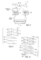
- FIG. 1 is a perspective view of a hand-held instrument projecting an image at a working distance therefrom;
- FIG. 2 is an enlarged, overhead, perspective view of an image projection arrangement for installation in the instrument of FIG. 1 ;
- FIG. 3 is a top plan view of the arrangement of FIG. 2 ;
- FIG. 4 is a perspective front view of an inertial drive for use in the arrangement of FIG. 2 ;
- FIG. 5 is a perspective rear view of the inertial drive of FIG. 4 ;
- FIG. 6 is a perspective view of a practical implementation of the arrangement of FIG. 2 ;
- FIG. 7 is an electrical schematic block diagram depicting operation of the arrangement of FIG. 2 ;
- FIG. 8 is an electrical schematic block diagram depicting an X-mirror drive circuit used in the arrangement of FIG. 6 ;
- FIG. 9 is a diagrammatic view depicting a raster pattern when the X-mirror is driven in one direction, as well as the resulting light pattern when the laser beam is turned on for only one direction;
- FIG. 10 is a diagrammatic view depicting a raster pattern when the X-mirror is driven in two directions, as well as the resulting light pattern when the laser beam is turned on for both directions;
- FIG. 11 is a timing circuit diagram explaining operation of the monitoring circuit according to this invention.
- FIG. 12 is another timing circuit diagram explaining operation of the monitoring circuit according to this invention.
- Reference numeral 10 in FIG. 1 generally identifies a hand-held instrument, for example, a personal digital assistant, in which a lightweight, compact, image projection arrangement 20 , as shown in FIG. 2 , is mounted and operative for projecting a two-dimensional color image on a projection surface at a variable distance from the instrument.
- a lightweight, compact, image projection arrangement 20 as shown in FIG. 2 , is mounted and operative for projecting a two-dimensional color image on a projection surface at a variable distance from the instrument.
- an image 18 is situated within a viewing range of distances relative to the instrument 10 .
- the image 18 extends over an optical horizontal scan angle A extending along the horizontal direction, and over an optical vertical scan angle B extending along the vertical direction, of the image.
- the image is comprised of illuminated and non-illuminated pixels on a raster pattern of scan lines swept by a scanner in the arrangement 20 .
- the parallelepiped shape of the instrument 10 represents just one form factor of a housing in which the arrangement 20 may be implemented.
- the instrument can be shaped with many different form factors, such as a pen, a cellular telephone, a clamshell or a wristwatch.
- the arrangement 20 measures about seventy cubic centimeters in volume. This compact, miniature size allows the arrangement 20 to be mounted in housings of many diverse shapes, large or small, portable or stationary, including some having an on-board display 12 , a keypad 14 , and a window 16 through which the image is projected.
- the arrangement 20 includes a solid-state, preferably a semiconductor laser 22 which, when energized, emits a bright red laser beam at about 635-655 nanometers.
- Lens 24 is a bi-aspheric convex lens having a positive focal length and is operative for collecting virtually all the energy in the red beam and for producing a diffraction-limited beam.
- Lens 26 is a concave lens having a negative focal length. Lenses 24 , 26 are held by non-illustrated respective lens holders apart on a support (not illustrated in FIG. 2 for clarity) inside the instrument 10 . The lenses 24 , 26 shape the red beam profile over the working distance.
- Another solid-state, semiconductor laser 28 is mounted on the support and, when energized, emits a diffraction-limited blue laser beam at about 440 nanometers.
- Another bi-aspheric convex lens 30 and a concave lens 32 are employed to shape the blue beam profile in a manner analogous to lenses 24 , 26 .
- a green laser beam having a wavelength on the order of 532 nanometers is generated not by a semiconductor laser, but instead by a green module 34 having an infrared diode-pumped, Nd-doped, YAG crystal laser whose output beam at 1064 nanometers.
- a non-linear frequency doubling crystal is included in the infrared laser cavity between two laser mirrors. Since the infrared laser power inside the cavity is much larger than the power coupled outside the cavity, the frequency doubler is more efficient in generating the double frequency green light inside the cavity.
- the output mirror of the laser is reflective to the 1064 nm infrared radiation, and transmissive to the doubled 532 nm green laser beam.
- thermo-electric cooler can either heat or cool the device depending on the polarity of the applied current.
- a thermistor is part of the green laser module in order to monitor its temperature. The readout from the thermistor is fed to a controller, which adjusts the control current to the thermo-electric cooler accordingly.
- the lasers are pulsed in operation at frequencies on the order of 100 MHz.
- the red and blue semiconductor lasers 22 , 28 can be pulsed directly via the applied drive currents at such high frequencies, but the currently available green solid-state lasers cannot.
- the green laser beam exiting the green module 34 is pulsed with an acousto-optical modulator (AOM) 36 that creates an acoustic traveling wave inside a crystal for diffracting the green beam.
- AOM 36 acousto-optical modulator
- the AOM 36 produces a zero-order, non-diffracted beam 38 and a first-order, pulsed, diffracted beam 40 .
- the beams 38 , 40 diverge from each other and, in order to separate them to eliminate the undesirable zero-order beam 38 , the beams 38 , 40 are routed along a long, folded path having a folding mirror 42 .
- the AOM can be used internally to the green laser module to pulse the green laser beam.
- Other possible ways to modulate the green laser beam include electro-absorption modulation, or a Mach-Zender interferometer.
- the beams 38 , 40 are routed through positive and negative lenses 44 , 46 . However, only the diffracted green beam 40 is allowed to impinge upon, and reflect from, the folding mirror 48 .
- the non-diffracted beam 38 may be absorbed by an absorber 50 , preferably mounted on the mirror 48 , or can be used for another useful function.
- the arrangement includes a pair of dichroic filters 52 , 54 arranged to make the green, blue and red beams as collinear as possible before reaching a scanning assembly 60 .
- Filter 52 allows the green beam 40 to pass therethrough, but the blue beam 56 from the blue laser 28 is reflected by the interference effect.
- Filter 54 allows the green and blue beams 40 , 56 to pass therethrough, but the red beam 58 from the red laser 22 is reflected by the interference effect.
- the nearly collinear beams 40 , 56 , 58 are directed to, and reflected off, a stationary fold mirror 62 .
- the scanning assembly 60 includes a first scan mirror 64 oscillatable by an inertial drive 66 (shown in isolation in FIGS. 4-5 ) at a first scan rate to sweep the laser beams reflected off the fold mirror 62 over the first horizontal scan angle A, and a second scan mirror 68 oscillatable by an electromagnetic drive 70 at a second scan rate to sweep the laser beams reflected off the first scan mirror 64 over the second vertical scan angle B.
- the scan mirrors 64 , 68 can be replaced by a single two-axis mirror.
- the inertial drive 66 is a high-speed, low electrical power-consuming component. Details of the inertial drive can be found in U.S. patent application Ser. No. 10/387,878, filed Mar. 13, 2003, assigned to the same assignee as the instant application, and incorporated herein by reference thereto.
- the use of the inertial drive reduces power consumption of the scanning assembly 60 to less than one watt and, in the case of projecting a color image, as described below, to less than ten watts.
- the drive 66 includes a movable frame 74 for supporting the scan mirror 64 by means of a hinge that includes a pair of collinear hinge portions 76 , 78 extending along a hinge axis and connected between opposite regions of the scan mirror 64 and opposite regions of the frame.
- the frame 74 need not surround the scan mirror 64 , as shown.
- the frame, hinge portions and scan mirror are fabricated of an integral, generally planar, silicon substrate, which is approximately 150 microns thick.
- the silicon is etched to form omega-shaped slots having upper parallel slot sections, lower parallel slot sections, and U-shaped central slot sections.
- the scan mirror 64 preferably has an oval shape and is free to move in the slot sections. In the preferred embodiment, the dimensions along the axes of the oval-shaped scan mirror measure 749 microns ⁇ 1600 microns.
- Each hinge portion measures 27 microns in width and 1130 microns in length.
- the frame has a rectangular shape measuring 3100 microns in width and 4600 microns in length.
- the inertial drive is mounted on a generally planar, printed circuit board 80 and is operative for directly moving the frame and, by inertia, for indirectly oscillating the scan mirror 64 about the hinge axis.
- One embodiment of the inertial drive includes a pair of piezoelectric transducers 82 , 84 extending perpendicularly of the board 80 and into contact with spaced apart portions of the frame 74 at either side of hinge portion 76 .
- An adhesive may be used to insure a permanent contact between one end of each transducer and each frame portion.
- the opposite end of each transducer projects out of the rear of the board 80 and is electrically connected by wires 86 , 88 to a periodic alternating voltage source (not shown).
- the periodic signal applies a periodic drive voltage to each transducer and causes the respective transducer to alternatingly extend and contract in length.
- transducer 82 extends
- transducer 84 contracts, and vice versa, thereby simultaneously pushing and pulling the spaced apart frame portions and causing the frame to twist about the hinge axis.
- the drive voltage has a frequency corresponding to the resonant frequency of the scan mirror.
- the scan mirror is moved from its initial rest position until it also oscillates about the hinge axis at the resonant frequency.
- the frame and the scan mirror are about 150 microns thick, and the scan mirror has a high Q factor. A movement on the order of 1 micron by each transducer can cause oscillation of the scan mirror at scan angles in excess of 15 degrees.
- Another pair of piezoelectric transducers 90 , 92 extends perpendicularly of the board 80 and into permanent contact with spaced apart portions of the frame 74 at either side of hinge portion 78 .
- Transducers 90 , 92 serve as feedback devices to monitor the oscillating movement of the frame and to generate and conduct electrical feedback signals along wires 94 , 96 to a feedback control circuit (not shown).
- the surface of the mirror 64 is desirable to coat the surface of the mirror 64 with a specular coating made of gold, silver, aluminum, or a specially designed highly reflective dielectric coating.
- the electromagnetic drive 70 includes a permanent magnet jointly mounted on and behind the second scan mirror 68 , and an electromagnetic coil 72 operative for generating a periodic magnetic field in response to receiving a periodic drive signal.
- the coil 72 is adjacent the magnet so that the periodic field magnetically interacts with the permanent field of the magnet and causes the magnet and, in turn, the second scan mirror 68 to oscillate.
- the inertial drive 66 oscillates the scan mirror 64 at a high speed at a scan rate preferably greater than 5 kHz and, more particularly, on the order of 18 kHz or more. This high scan rate is at an inaudible frequency, thereby minimizing noise and vibration.
- the electromagnetic drive 70 oscillates the scan mirror 68 at a slower scan rate on the order of 40 Hz which is fast enough to allow the image to persist on a human eye retina without excessive flicker.
- the faster mirror 64 sweeps a generally horizontal scan line
- the slower mirror 68 sweeps the generally horizontal scan line vertically, thereby creating a raster pattern which is a grid or sequence of roughly parallel scan lines from which the image is constructed.
- Each scan line has a number of pixels.
- the image resolution is preferably XGA quality of 1024 ⁇ 768 pixels.
- a high-definition television standard denoted 720p, 1270 ⁇ 720 pixels, can be obtained.
- a one-half VGA quality of 320 ⁇ 480 pixels, or one-fourth VGA quality of 320 ⁇ 240 pixels is sufficient.
- a resolution of 160 ⁇ 160 pixels is desired.
- mirror 64 , 68 could be reversed so that mirror 68 is the faster, and mirror 64 is the slower.
- Mirror 64 can also be designed to sweep the vertical scan line, in which event, mirror 68 would sweep the horizontal scan line.
- the inertial drive can be used to drive the mirror 68 . Indeed, either mirror can be driven by an electromechanical, electrical, mechanical, electrostatic, magnetic, or electromagnetic drive.
- the slow-mirror is operated in a constant velocity sweep-mode during which time the image is displayed. During the mirror's return, the mirror is swept back into the initial position at its natural frequency, which is significantly higher. During the mirror's return trip, the lasers can be powered down in order to reduce the power consumption of the device.
- FIG. 6 is a practical implementation of the arrangement 20 in the same perspective as that of FIG. 2 .
- the aforementioned components are mounted on a support, which includes a top cover 100 and a support plate 102 .
- Holders 104 , 106 , 108 , 110 , 112 respectively hold folding mirrors 42 , 48 , filters 52 , 54 and fold mirror 62 in mutual alignment.
- Each holder has a plurality of positioning slots for receiving positioning posts stationarily mounted on the support. Thus, the mirrors and filters are correctly positioned. As shown, there are three posts, thereby permitting two angular adjustments and one lateral adjustment.
- Each holder can be glued in its final position.
- the image is constructed by selective illumination of the pixels in one or more of the scan lines.
- a controller 114 causes selected pixels in the raster pattern to be illuminated, and rendered visible, by the three laser beams.
- red, blue and green power controllers 116 , 118 , 120 respectively conduct electrical currents to the red, blue and green lasers 22 , 28 , 34 to energize the latter to emit respective light beams at each selected pixel, and do not conduct electrical currents to the red, blue and green lasers to deenergize the latter to non-illuminate the other non-selected pixels.
- the resulting pattern of illuminated and non-illuminated pixels comprises the image, which can be any display of human- or machine-readable information or graphic.
- the raster pattern is shown in an enlarged view.
- the laser beams are swept by the inertial drive along the generally horizontal direction at the horizontal scan rate to an opposite end point to form a scan line.
- the laser beams are swept by the electromagnetic drive 70 along the vertical direction at the vertical scan rate to another end point to form a second scan line.
- the formation of successive scan lines proceeds in the same manner.
- the image is created in the raster pattern by energizing or pulsing the lasers on and off at selected times under control of the microprocessor 114 or control circuit by operation of the power controllers 116 , 118 , 120 .
- the lasers produce visible light and are turned on only when a pixel in the desired image is desired to be seen.
- the color of each pixel is determined by one or more of the colors of the beams. Any color in the visible light spectrum can be formed by the selective superimposition of one or more of the red, blue, and green lasers.
- the raster pattern is a grid made of multiple pixels on each line, and of multiple lines.
- the image is a bit-map of selected pixels. Every letter or number, any graphical design or logo, and even machine-readable bar code symbols, can be formed as a bit-mapped image.
- an incoming video signal having vertical and horizontal synchronization data, as well as pixel and clock data, is sent to red, blue and green buffers 122 , 124 , 126 under control of the microprocessor 114 .
- the storage of one full VGA frame requires many kilobytes, and it would be desirable to have enough memory in the buffers for two full frames to enable one frame to be written, while another frame is being processed and projected.
- the buffered data is sent to a formatter 128 under control of a speed profiler 130 and to red, blue and green look up tables (LUTs) 132 , 134 , 136 to correct inherent internal distortions caused by scanning, as well as geometrical distortions caused by the angle of the display of the projected image.
- LUTs red, blue and green look up tables
- the resulting red, blue and green digital signals are converted to red, blue and green analog signals by digital to analog converters (DACs) 138 , 140 , 142 .
- the red and blue analog signals are fed to red and blue laser drivers (LDs) 144 , 146 which are also connected to the red and blue power controllers 116 , 118 .
- the green analog signal is fed to an acousto-optical module (AOM) radio frequency (RF) driver 150 and, in turn, to the green laser 34 which is also connected to a green LD 148 and to the green power controller 120 .
- AOM acousto-optical module
- RF radio frequency
- Feedback controls are also shown in FIG. 7 , including red, blue and green photodiode amplifiers 152 , 154 , 156 connected to red, blue and green analog-to-digital (A/D) converters 158 , 160 , 162 and, in turn, to the microprocessor 114 .
- Heat is monitored by a thermistor amplifier 164 connected to an A/D converter 166 and, in turn, to the microprocessor.
- the scan mirrors 64 , 68 are driven by drivers 168 , 170 which are fed analog drive signals from DACs 172 , 174 which are, in turn, connected to the microprocessor.
- Feedback amplifiers 176 , 178 detect the position of the scan mirrors 64 , 68 , and are connected to feedback A/Ds 180 , 182 and, in turn, to the microprocessor.
- a power management circuit 184 is operative to minimize power while allowing fast on-times, preferably by keeping the green laser on all the time, and by keeping the current of the red and blue lasers just below the lasing threshold.
- a laser safety shut down circuit 186 is operative to shut the lasers off if either of the scan mirrors 64 , 68 is detected as being outside of rated values.
- the drive 66 includes a permanent magnet 210 mounted on the scan mirror 64 for joint oscillation.
- a feedback coil 212 is positioned adjacent the magnet 210 .
- a feedback signal is generated by the feedback coil 212 during oscillation.
- a feedback circuit 176 is employed, for example, to process the zero crossings of the feedback signal to derive a start-of-scan (SOS) signal that represents mirror motion and is used to synchronize the scan lines.
- SOS start-of-scan
- the feedback signal can be contaminated by the periodic drive signal voltage, as well as by the switching electronics 168 of the drive 66 for producing the periodic drive signal voltage.
- the periodic drive signal voltage couples to the feedback coil 212 and adds to the voltage of the feedback signal. Since the contaminants are synchronous with the feedback signal, it is not readily possible to remove the contaminants by signal processing. Hence, the position of the mirror cannot be precisely located. Such contamination is a severe problem in image projectors, because the motion or velocity of the scan mirror and, hence, of each scan line swept by the scan mirror must be very highly controlled to be a constant value for both right-to-left and left-to-right scan lines. Otherwise, the projected image will be degraded.
- FIGS. 9-10 illustrate the raster pattern of the combined X-mirror 64 and Y-mirror 68 motion.
- FIG. 9 illustrates a case where the lasers project the image when the mirror 64 moves in one direction, say from left to right and produce scans 201 _i, 201 _i+1, 201 _i+2, etc. During these scans, the lasers project scan lines 203 — i , 203 _i+1, 203 _i+2, etc., respectively. The laser beams are turned off during the return from right to left and produce scans 202 _i, 202 _i+1, 202 _i+2, etc.
- FIG. 10 illustrates a case where the lasers project the image during X-mirror 64 movement in both directions.
- the lasers project scan lines 304 _i, 304 _i+1, 304 _i+2, etc., respectively.
- the lasers project scan lines 305 _i, 305 _i+1, 305 _i+2, etc., respectively.
- FIG. 10 illustrates that the scan lines projected during left-to-right scans are shifted in respect to the scan lines projected during right-to-left scans. This is because of the error in determining the mirror position and consequently determining the exact beginning of the scan line. If the scan lines are displayed only in one direction (such as in FIG. 9 ), such error is inconsequential because the entire image is just slightly shifted in one direction.
- bi-directional scanning there are two images displayed: one during left-to-right scans and the other during right-to-left scans. While each of the images is good in itself, they are shifted in respect to each other. This is highly undesirable and results in blurring of the displayed image. The tolerable limit of such shift is just a fraction of one pixel. This puts a severe burden on the accuracy of the position reading of the X-mirror.
- point 303 corresponds to the exact time when the mirror 64 changes direction. This time is measured by the feedback circuit, which uses this measurement to properly modulate the laser beam. If the error in the time measurement is e r , the left-to-right image is shifted in respect to the right-to-left image by 2*e r .
- FIG. 11 depicts how the X-mirror position can be accurately measured by elimination of the drive voltage impact on the feedback signal.
- the X-mirror is driven by a periodic waveform of a train of pulses of which only pulses 501 through 507 are indicated in the drawing. The pulses are separated by intervals established by the control electronics. These intervals establish the X-mirror period.
- pulses 503 and 504 are shown as removed pulses 503 a and 504 a in the period 511 .
- the X-mirror will oscillate at its resonance frequency due its resonant nature. Because of the relatively high Q of the X-mirror, the oscillations can last a very long time without driving voltage pulses. However, there may be accumulated phase slip of the X-mirror position in respect to the driving pulses timing if there is some frequency difference between the X-mirror resonance frequency and the frequency of the driving pulses. There will also be amplitude loss depending on the Q of the X-mirror. If the driving pulses resume, the mirror phase and amplitude will be asymptotically corrected; however, it may take a long time for the correction.
- each pulse has more energy than normally required to sustain X-mirror oscillation of the desired amplitude.
- normal pulses 507 , etc. are resumed in the following period 509 .
- the entire measurement and the compensating pulses are completed during the time of the vertical blanking interval during which the laser beam is turned off and the image is not displayed.
- FIG. 12 illustrates more details of the compensating pulses.
- the energy lost due to removal of the pulses 503 a and 504 a , etc. is added back and spread in the following pulses by increasing the energy of the pulses 505 a and 506 a , etc.
- the spreading may be uniform or non-uniform.
- a more refined method may use overdriving (first adding more energy than was lost, and then subtracting the difference). This would even more speed up the recovery.
- flexibility of “padding” the X-drive compensating pulses on one side or both sides should be provided. This would ensure that the pulse center position does not change.
Abstract
Description
Claims (46)
Priority Applications (1)
| Application Number | Priority Date | Filing Date | Title |
|---|---|---|---|
| US11/796,151 US7815119B2 (en) | 2006-06-06 | 2007-04-26 | Monitoring scan mirror motion in laser scanning arrangements |
Applications Claiming Priority (2)
| Application Number | Priority Date | Filing Date | Title |
|---|---|---|---|
| US81121506P | 2006-06-06 | 2006-06-06 | |
| US11/796,151 US7815119B2 (en) | 2006-06-06 | 2007-04-26 | Monitoring scan mirror motion in laser scanning arrangements |
Publications (2)
| Publication Number | Publication Date |
|---|---|
| US20070278311A1 US20070278311A1 (en) | 2007-12-06 |
| US7815119B2 true US7815119B2 (en) | 2010-10-19 |
Family
ID=38788963
Family Applications (1)
| Application Number | Title | Priority Date | Filing Date |
|---|---|---|---|
| US11/796,151 Expired - Fee Related US7815119B2 (en) | 2006-06-06 | 2007-04-26 | Monitoring scan mirror motion in laser scanning arrangements |
Country Status (1)
| Country | Link |
|---|---|
| US (1) | US7815119B2 (en) |
Cited By (1)
| Publication number | Priority date | Publication date | Assignee | Title |
|---|---|---|---|---|
| US20090245299A1 (en) * | 2008-03-25 | 2009-10-01 | Motorola, Inc. | Capacitive comb feedback for high speed scan mirror |
Families Citing this family (7)
| Publication number | Priority date | Publication date | Assignee | Title |
|---|---|---|---|---|
| US8437587B2 (en) * | 2007-07-25 | 2013-05-07 | University Of Washington | Actuating an optical fiber with a piezoelectric actuator and detecting voltages generated by the piezoelectric actuator |
| US20090251670A1 (en) * | 2008-04-03 | 2009-10-08 | Motorola, Inc. | Optical feedback for high speed scan mirror |
| RU2544457C2 (en) | 2009-05-15 | 2015-03-20 | Конинклейке Филипс Электроникс Н.В. | Feedback corrected optical probe |
| US20140160439A1 (en) * | 2012-12-10 | 2014-06-12 | Funai Electric Co., Ltd. | Image display device |
| USD737822S1 (en) | 2014-03-10 | 2015-09-01 | Datalogic Ip Tech S.R.L. | Optical module |
| USD805078S1 (en) | 2015-05-07 | 2017-12-12 | Datalogic Ip Tech S.R.L. | Barcode reading module |
| JP7177351B2 (en) * | 2019-02-25 | 2022-11-24 | ミツミ電機株式会社 | Optical scanning device and its control method |
Citations (9)
| Publication number | Priority date | Publication date | Assignee | Title |
|---|---|---|---|---|
| US4160913A (en) * | 1977-08-05 | 1979-07-10 | St. Regis Paper Company | Web scanning apparatus |
| US5691739A (en) * | 1994-08-02 | 1997-11-25 | Sharp Kabushiki Kaisha | Driving device for a liquid crystal display which uses compensating pulses to correct for irregularities in brightness due to cross talk |
| US6691919B1 (en) * | 1998-03-24 | 2004-02-17 | Symbol Technologies, Inc. | Integrated bar code scanner and communications module |
| US7126734B1 (en) * | 2005-09-12 | 2006-10-24 | Symbol Technologies, Inc. | Motor drive circuit with reduced coil crosstalk in a feedback signal indicative of mirror motion in light scanning arrangements |
| US7130095B1 (en) * | 2005-06-24 | 2006-10-31 | Symbol Technologies, Inc. | Correcting for image distortion in image projectors |
| US20060289653A1 (en) * | 2005-06-24 | 2006-12-28 | Carl Wittenberg | Taut, torsional flexure and a compact drive for, and method of, scanning light using the flexure |
| US20060290774A1 (en) * | 2005-06-24 | 2006-12-28 | Carl Wittenberg | Arrangement for, and a method of, reducing image distortion due to electrical interference |
| US20070181688A1 (en) * | 2004-09-30 | 2007-08-09 | Yajun Li | Monitoring light beam position in electro-optical readers and image projectors |
| US20080320426A1 (en) * | 2005-02-03 | 2008-12-25 | Sage Software, Inc. | Method for Verifying Timing of a Circuit with Crosstalk Victim and Aggressor |
-
2007
- 2007-04-26 US US11/796,151 patent/US7815119B2/en not_active Expired - Fee Related
Patent Citations (9)
| Publication number | Priority date | Publication date | Assignee | Title |
|---|---|---|---|---|
| US4160913A (en) * | 1977-08-05 | 1979-07-10 | St. Regis Paper Company | Web scanning apparatus |
| US5691739A (en) * | 1994-08-02 | 1997-11-25 | Sharp Kabushiki Kaisha | Driving device for a liquid crystal display which uses compensating pulses to correct for irregularities in brightness due to cross talk |
| US6691919B1 (en) * | 1998-03-24 | 2004-02-17 | Symbol Technologies, Inc. | Integrated bar code scanner and communications module |
| US20070181688A1 (en) * | 2004-09-30 | 2007-08-09 | Yajun Li | Monitoring light beam position in electro-optical readers and image projectors |
| US20080320426A1 (en) * | 2005-02-03 | 2008-12-25 | Sage Software, Inc. | Method for Verifying Timing of a Circuit with Crosstalk Victim and Aggressor |
| US7130095B1 (en) * | 2005-06-24 | 2006-10-31 | Symbol Technologies, Inc. | Correcting for image distortion in image projectors |
| US20060289653A1 (en) * | 2005-06-24 | 2006-12-28 | Carl Wittenberg | Taut, torsional flexure and a compact drive for, and method of, scanning light using the flexure |
| US20060290774A1 (en) * | 2005-06-24 | 2006-12-28 | Carl Wittenberg | Arrangement for, and a method of, reducing image distortion due to electrical interference |
| US7126734B1 (en) * | 2005-09-12 | 2006-10-24 | Symbol Technologies, Inc. | Motor drive circuit with reduced coil crosstalk in a feedback signal indicative of mirror motion in light scanning arrangements |
Cited By (2)
| Publication number | Priority date | Publication date | Assignee | Title |
|---|---|---|---|---|
| US20090245299A1 (en) * | 2008-03-25 | 2009-10-01 | Motorola, Inc. | Capacitive comb feedback for high speed scan mirror |
| US7997742B2 (en) * | 2008-03-25 | 2011-08-16 | Microvision, Inc. | Capacitive comb feedback for high speed scan mirror |
Also Published As
| Publication number | Publication date |
|---|---|
| US20070278311A1 (en) | 2007-12-06 |
Similar Documents
| Publication | Publication Date | Title |
|---|---|---|
| US7859600B2 (en) | Arrangement for and method of projecting a level image | |
| US7367682B2 (en) | Color image projection arrangement and method | |
| US7130095B1 (en) | Correcting for image distortion in image projectors | |
| US7352499B2 (en) | Arrangement for and method of projecting an image with pixel mapping | |
| US7059523B1 (en) | Scan line alignment in raster pattern | |
| US7312911B2 (en) | Arrangement for and method of improving image quality, especially for image projection arrangements | |
| US7924349B2 (en) | Arrangement for and method of projecting an image with linear scan lines | |
| EP2035893B1 (en) | Arrangement for and method of projecting an image with safety circuitry | |
| US7815119B2 (en) | Monitoring scan mirror motion in laser scanning arrangements | |
| US7859567B2 (en) | Arrangement for and method of projecting a color image by switching scan directions in alternate frames | |
| US7497578B2 (en) | Monitoring scan mirror motion in electro-optical readers and image projectors | |
| US7460287B2 (en) | Arrangement for and method of increasing pixel symmetry, especially for image projection arrangements | |
| US20070279536A1 (en) | Arrangement for and method of projecting an image to be viewed over extended viewing range | |
| US20070279509A1 (en) | Arrangement for and method of projecting an image with modulated lasers | |
| US7468508B2 (en) | System for and method of projecting an image and adjusting a data frequency of a video signal during image projection | |
| US20080204541A1 (en) | Aperture stop in an image projection arrangement for preserving color fidelity over an image |
Legal Events
| Date | Code | Title | Description |
|---|---|---|---|
| AS | Assignment |
Owner name: SYMBOL TECHNOLOGIES, INC., NEW YORK Free format text: ASSIGNMENT OF ASSIGNORS INTEREST;ASSIGNOR:PARTYKA, ANDRZEJ;REEL/FRAME:019643/0206 Effective date: 20070629 |
|
| STCF | Information on status: patent grant |
Free format text: PATENTED CASE |
|
| AS | Assignment |
Owner name: MICROVISION, INC., WASHINGTON Free format text: ASSIGNMENT OF ASSIGNORS INTEREST;ASSIGNOR:SYMBOL TECHNOLOGIES, INC.;REEL/FRAME:025314/0798 Effective date: 20101029 |
|
| FPAY | Fee payment |
Year of fee payment: 4 |
|
| MAFP | Maintenance fee payment |
Free format text: PAYMENT OF MAINTENANCE FEE, 8TH YEAR, LARGE ENTITY (ORIGINAL EVENT CODE: M1552) Year of fee payment: 8 |
|
| FEPP | Fee payment procedure |
Free format text: MAINTENANCE FEE REMINDER MAILED (ORIGINAL EVENT CODE: REM.); ENTITY STATUS OF PATENT OWNER: LARGE ENTITY |
|
| LAPS | Lapse for failure to pay maintenance fees |
Free format text: PATENT EXPIRED FOR FAILURE TO PAY MAINTENANCE FEES (ORIGINAL EVENT CODE: EXP.); ENTITY STATUS OF PATENT OWNER: LARGE ENTITY |
|
| STCH | Information on status: patent discontinuation |
Free format text: PATENT EXPIRED DUE TO NONPAYMENT OF MAINTENANCE FEES UNDER 37 CFR 1.362 |
|
| FP | Lapsed due to failure to pay maintenance fee |
Effective date: 20221019 |