US7806653B2 - Gas turbine engines including multi-curve stator vanes and methods of assembling the same - Google Patents
Gas turbine engines including multi-curve stator vanes and methods of assembling the same Download PDFInfo
- Publication number
- US7806653B2 US7806653B2 US11/615,556 US61555606A US7806653B2 US 7806653 B2 US7806653 B2 US 7806653B2 US 61555606 A US61555606 A US 61555606A US 7806653 B2 US7806653 B2 US 7806653B2
- Authority
- US
- United States
- Prior art keywords
- root portion
- midpoint
- stator
- vane
- tip portion
- Prior art date
- Legal status (The legal status is an assumption and is not a legal conclusion. Google has not performed a legal analysis and makes no representation as to the accuracy of the status listed.)
- Active, expires
Links
Images


Classifications
-
- F—MECHANICAL ENGINEERING; LIGHTING; HEATING; WEAPONS; BLASTING
- F01—MACHINES OR ENGINES IN GENERAL; ENGINE PLANTS IN GENERAL; STEAM ENGINES
- F01D—NON-POSITIVE DISPLACEMENT MACHINES OR ENGINES, e.g. STEAM TURBINES
- F01D5/00—Blades; Blade-carrying members; Heating, heat-insulating, cooling or antivibration means on the blades or the members
- F01D5/12—Blades
- F01D5/14—Form or construction
- F01D5/141—Shape, i.e. outer, aerodynamic form
- F01D5/145—Means for influencing boundary layers or secondary circulations
-
- F—MECHANICAL ENGINEERING; LIGHTING; HEATING; WEAPONS; BLASTING
- F01—MACHINES OR ENGINES IN GENERAL; ENGINE PLANTS IN GENERAL; STEAM ENGINES
- F01D—NON-POSITIVE DISPLACEMENT MACHINES OR ENGINES, e.g. STEAM TURBINES
- F01D9/00—Stators
- F01D9/02—Nozzles; Nozzle boxes; Stator blades; Guide conduits, e.g. individual nozzles
- F01D9/04—Nozzles; Nozzle boxes; Stator blades; Guide conduits, e.g. individual nozzles forming ring or sector
- F01D9/041—Nozzles; Nozzle boxes; Stator blades; Guide conduits, e.g. individual nozzles forming ring or sector using blades
-
- F—MECHANICAL ENGINEERING; LIGHTING; HEATING; WEAPONS; BLASTING
- F05—INDEXING SCHEMES RELATING TO ENGINES OR PUMPS IN VARIOUS SUBCLASSES OF CLASSES F01-F04
- F05D—INDEXING SCHEME FOR ASPECTS RELATING TO NON-POSITIVE-DISPLACEMENT MACHINES OR ENGINES, GAS-TURBINES OR JET-PROPULSION PLANTS
- F05D2240/00—Components
- F05D2240/20—Rotors
- F05D2240/30—Characteristics of rotor blades, i.e. of any element transforming dynamic fluid energy to or from rotational energy and being attached to a rotor
- F05D2240/301—Cross-sectional characteristics
-
- F—MECHANICAL ENGINEERING; LIGHTING; HEATING; WEAPONS; BLASTING
- F05—INDEXING SCHEMES RELATING TO ENGINES OR PUMPS IN VARIOUS SUBCLASSES OF CLASSES F01-F04
- F05D—INDEXING SCHEME FOR ASPECTS RELATING TO NON-POSITIVE-DISPLACEMENT MACHINES OR ENGINES, GAS-TURBINES OR JET-PROPULSION PLANTS
- F05D2250/00—Geometry
- F05D2250/60—Structure; Surface texture
- F05D2250/61—Structure; Surface texture corrugated
- F05D2250/611—Structure; Surface texture corrugated undulated
-
- F—MECHANICAL ENGINEERING; LIGHTING; HEATING; WEAPONS; BLASTING
- F05—INDEXING SCHEMES RELATING TO ENGINES OR PUMPS IN VARIOUS SUBCLASSES OF CLASSES F01-F04
- F05D—INDEXING SCHEME FOR ASPECTS RELATING TO NON-POSITIVE-DISPLACEMENT MACHINES OR ENGINES, GAS-TURBINES OR JET-PROPULSION PLANTS
- F05D2250/00—Geometry
- F05D2250/70—Shape
- F05D2250/71—Shape curved
-
- Y—GENERAL TAGGING OF NEW TECHNOLOGICAL DEVELOPMENTS; GENERAL TAGGING OF CROSS-SECTIONAL TECHNOLOGIES SPANNING OVER SEVERAL SECTIONS OF THE IPC; TECHNICAL SUBJECTS COVERED BY FORMER USPC CROSS-REFERENCE ART COLLECTIONS [XRACs] AND DIGESTS
- Y02—TECHNOLOGIES OR APPLICATIONS FOR MITIGATION OR ADAPTATION AGAINST CLIMATE CHANGE
- Y02T—CLIMATE CHANGE MITIGATION TECHNOLOGIES RELATED TO TRANSPORTATION
- Y02T50/00—Aeronautics or air transport
- Y02T50/60—Efficient propulsion technologies, e.g. for aircraft
Definitions
- This invention relates generally to gas turbine engines, and more specifically to turbine nozzle assemblies in gas turbine engines.
- combustion gases flow through a high-pressure turbine and a low-pressure turbine to generate torque, which powers the upstream compressor and fan.
- the low-pressure turbine is rotatably coupled to a front fan assembly. Stator vanes in the low-pressure turbine channel combustion gases downstream towards a row of rotating turbine blades. The gas flow induces rotation to the turbine blades which causes rotation of the front fan assembly.
- the flowfield of the combustion gases that travel through the turbines can be complex.
- portions of the outer surfaces of the vanes, blades, and/or other components of the turbine assembly may induce secondary flows in the combustion gases that are perpendicular to the direction of the core flow.
- Such secondary flows may cause an undesirable loss in pressure and a reduction in engine efficiency.
- Optimizing the surroundings of the flowfield may facilitate reducing pressure losses and improving engine efficiency.
- a method for assembling a gas turbine engine includes coupling at least one stator assembly that has at least one stator vane extending from an inner band within the gas turbine engine.
- the stator vane extends from a root portion extending from the inner band to a tip portion.
- the stator vane includes at least one lean directional change and a plurality of sweep directional changes that are defined between the root portion and the tip portion.
- the method also includes coupling at least one turbine blade assembly having at least one rotor blade downstream from the stator assembly.
- a stator vane in another aspect, includes an airfoil having a first sidewall and a second sidewall that is coupled to the first sidewall at a leading edge and at a trailing edge.
- the airfoil extends radially from a root portion to a tip portion.
- Each of the leading and trailing edges includes at least one lean directional change and a plurality of sweep directional changes that are defined between the root portion and the tip portion.
- a turbine nozzle assembly in another aspect, includes a radially inner band and at least one stator vane that extends radially outward from the inner band.
- the stator vane includes an airfoil having a root portion that extends from the inner band to a tip portion.
- the airfoil also includes at least one lean directional change and a plurality of sweep directional changes that are defined between the root portion and the tip portion.
- FIG. 1 is a schematic illustration of an exemplary gas turbine engine
- FIG. 2 is a side view of an exemplary known turbine nozzle assembly that may be used in the gas turbine engine shown in FIG. 1 ;
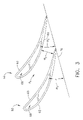
- FIG. 3 is a cross-sectional view of two known stator vanes that may be used with the nozzle assembly shown in FIG. 2 ;
- FIG. 4 illustrates an exemplary multi-curve vane that may be used in the gas turbine engine shown in FIG. 1 ;
- FIG. 5 illustrates a centerline cross-sectional view of the multi-curve vane shown in FIG. 4 ;
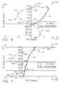
- FIG. 6 is a graph illustrating exemplary lean angle values at the leading edge of the multi-curve vane shown in FIG. 4 ;
- FIG. 7 is a graph illustrating exemplary lean angle values at the trailing edge of the multi-curve vane shown in FIG. 4 ;
- FIG. 8 is a side-perspective view of an exemplary sweep angle of the multi-curve vane shown in FIG. 4 ;
- FIG. 9 is a graph illustrating exemplary sweep angle values at the leading edge of the multi-curve vane shown in FIG. 4 ;
- FIG. 10 is a graph illustrating exemplary sweep angle values at the trailing edge of the multi-curve vane shown in FIG. 4 ;
- FIG. 11 is a graph illustrating exemplary cross-sectional area values of the multi-curve vane shown in FIG. 4 .
- the present invention provides a method and components that facilitate reducing secondary flows in gas turbine engines, such that engine efficiency is facilitated to be increased.
- embodiments discussed herein include stator vanes, turbine assemblies, gas turbine engines, and methods of manufacturing the same, those having ordinary skill in the art will appreciate that the present invention is not limited to use with gas turbine engines or any of the exemplary embodiments described or illustrated herein.
- FIG. 1 is a schematic illustration of an exemplary gas turbine engine 10 including a fan assembly 12 , a high-pressure compressor 14 , and a combustor 16 .
- Engine 10 also includes a high-pressure turbine 18 and a low-pressure turbine 20 .
- Fan assembly 12 and low-pressure turbine 20 are coupled by a first shaft 21
- compressor 14 and high-pressure turbine 18 are coupled by a second shaft 22 .
- gas turbine engine 10 is a GE90 engine commercially available from General Electric Aircraft Engines, Cincinnati, Ohio.
- the highly compressed air is delivered to combustor 16 .
- Airflow from combustor 16 is channeled through one or more turbine nozzle assemblies (not shown in FIG. 1 ) to drive turbines 18 and 20 , prior to exiting gas turbine engine 10 through an exhaust nozzle 24 .
- pressurized air from high-pressure compressor 14 is mixed with fuel in combustor 16 and ignited, thereby generating combustion gases.
- the combustion gases induce rotation of high-pressure turbine 18 which causes rotation of high-pressure compressor 14 .
- the combustion gases are discharged from high-pressure turbine 18 into low-pressure turbine 20 .
- the core airflow is discharged from low-pressure turbine 20 and directed aftward towards exhaust nozzle 24 .
- FIG. 2 is a side view of an exemplary turbine nozzle assembly 50 that may be used with a turbine engine, such as but not limited to gas turbine engine 10 (shown in FIG. 1 ).
- a turbine engine such as but not limited to gas turbine engine 10 (shown in FIG. 1 ).
- Nozzle assembly 50 includes a stator vane 52 that includes an airfoil 53 formed by a pressure-side sidewall 60 and a suction-side sidewall 62 that are joined together at a leading edge 64 and at a chordwise-spaced trailing edge 66 such that a cooling cavity (not shown in FIG.
- Airfoil sidewalls 60 and 62 each extend radially between an outer band 54 and an inner band 56 .
- sidewall 60 is concave
- sidewall 62 is convex such that stator vane 52 has a cambered profile.
- airfoil 53 includes a tip portion 282 and a root portion 284 .
- Outer band 54 includes a leading edge surface 70 , a trailing edge surface 74 , and a body 78 extending therebetween.
- Inner band 56 includes a leading edge surface 72 , a trailing edge surface 76 , and a body 80 extending therebetween.
- stator vane 52 is oriented such that outer and inner band leading edge surfaces 70 and 72 , respectively, are each a distance d upstream from stator vane leading edge 64 .
- FIG. 3 is a bottom cross-sectional view of a pair of adjacent stator vanes 52 that may be used with turbine nozzle assembly 50 .
- Stator vanes 52 are each oriented at an angle ⁇ 1 with respect to trailing edge 76 on inner band 56 such that a throat area A 1 is defined between vanes 52 .
- angle ⁇ 1 By adjusting angle ⁇ 1 , a width W 1 of throat area A 1 can be increased or decreased. More specifically, increasing throat area A 1 facilitates increasing a mass flow of air channeled between stator vanes 52 , and decreasing throat area A 1 facilitates decreasing the mass flow of air channeled between stator vanes 52 .
- FIGS. 4 and 5 illustrate an exemplary multi-curve vane 122 that may be used with turbine nozzle assembly 50 . More specifically, FIG. 4 is a perspective view of vane 122 and includes three exemplary orthogonal axes including an axial axis (X-axis), a tangential or circumferential axis (Y-axis), and a radial axis (Z-axis).
- FIG. 5 illustrates a cross-sectional view of vane 122 taken through centerline 150 and along the Y-Z plane. Centerline 150 extends from root portion 184 to tip portion 182 along the surface of sidewall 62 .
- the X-axis extends downstream relative to flowpath 30
- the Z-axis extends radially outwardly from inner band 56 (shown in FIG. 2 )
- the Y-axis extends in the circumferential direction.
- lean is defined as a radial angle ⁇ L defined between a surface tangent 152 of vane 122 in Y-Z plane and a line 154 extending substantially parallel to the Z-axis.
- the amount of lean of vane 122 is referred to as “tilt.” If a portion of stator vane 122 has a negative radial angle ⁇ L with respect to line 154 (as shown in FIG. 5 ), then that portion of vane 122 has a forward lean. If a portion of stator vane 122 has a positive radial angle ⁇ L with respect to line 154 , then that portion of vane 122 has a backward lean.
- vane 122 includes an airfoil 123 including a plurality of lean portions.
- lean portion refers to a radially-extending portion of vane 122 that is defined between a pair of radially adjacent lean directional changes, or between a lean directional change and tip portion 282 , or between an lean directional change and root portion 284 .
- lean directional change refers to a point defined on airfoil 123 in which the direction of lean changes from a forward lean to a backward lean, or vice-versa.
- FIG. 6 is a graph 410 illustrating exemplary lean angle values 172 corresponding to leading edge 64 of vane 122 . More specifically, the lean angle values 172 associated with leading edge 64 are plotted graphically wherein the ordinate 412 of graph 410 represents a percent of span of airfoil 123 , and the abscissa 416 of graph 410 represents an amount of lean angle ⁇ L , as measured in degrees, of leading edge 64 .
- a solid line 170 represents an amount of lean associated with a conventional stator vane. Accordingly, at root portion 284 , represented at a radial span of 0%, the lean angle value 172 of leading edge 64 is approximately equal to 4°.
- vane 122 includes two lean directional changes 174 and 176 defined on leading edge 64 .
- vane 122 may include any number of lean directional changes defined on leading edge 64 .
- airfoil 123 includes three lean portions 302 , 304 , and 306 defined along leading edge 64 .
- a first lean portion 302 is defined between root portion 284 and directional change 174
- a second lean portion 304 is defined between directional change 174 and directional change 176
- a third lean portion 306 is defined between directional change 176 and tip portion 282 .
- leading edge 64 includes one lean portion 302 defined between root portion 284 and a midpoint 420 of airfoil 123 .
- lean portion 302 extends across approximately 40% of airfoil 123 .
- Second lean portion 304 begins between root portion 284 and midpoint 420 and extends across approximately 45% of airfoil 123 .
- leading edge 64 has a reverse S-shape.
- vane 122 may have any number of lean portions forming a variety of shapes on leading edge 64 .
- FIG. 7 is a graph 430 illustrating exemplary lean angle values 180 corresponding to trailing edge 66 of vane 122 . More specifically, the lean angle values 180 associated with trailing edge 66 are plotted graphically wherein the ordinate 432 of graph 430 represents a percent of span of airfoil 123 , extending from root portion 284 to tip portion 282 , and the abscissa 436 of graph 430 represents an amount of lean angle ⁇ L , in degrees, for trailing edge 66 .
- a solid line 178 represents an amount of lean associated with a conventional stator vane.
- the lean angle value 180 of trailing edge 66 is approximately equal to ⁇ 6°.
- vane 122 includes three lean directional changes 182 , 184 , and 186 defined on trailing edge 66 .
- vane 122 may include any number of lean directional changes defined on trailing edge 66 .
- vane 122 includes four lean portions 308 , 310 , 312 , and 314 defined along trailing edge 66 .
- a first lean portion 308 is defined between root portion 284 and directional change 182
- a second lean portion 310 is defined between directional change 182 and directional change 184
- a third lean portion 312 is defined between directional change 184 and directional change 186
- a fourth lean portion 314 is defined between directional change 186 and tip portion 282 .
- vane 122 includes two lean portions 308 and 310 that are defined before midpoint 420 .
- trailing edge 66 has a S-shape.
- vane 122 may include any number of lean portions defined before or after midpoint 420 and may have a variety of shapes.
- FIG. 8 illustrates an exemplary sweep angle as oriented on vane 122 .
- the term “sweep” is defined as a radial angle ⁇ S defined between a surface tangent 188 to vane 122 in the X-Z plane and a nominal line 190 extending substantially parallel to the Z-axis. If a portion of stator vane 122 has a negative radial angle ⁇ S with respect to line 190 , then that portion of stator vane 122 has a backward sweep. If a portion of stator vane 122 has a positive radial angle ⁇ S with respect to line 190 , then that portion of vane 122 has a forward sweep.
- airfoil 123 includes a plurality of sweep portions 352 , 354 , 356 , 358 , 360 , 362 , and 364 .
- the term “sweep portion” refers to a radially-extending portion of vane 122 that is defined between a pair of radially adjacent sweep directional changes, or between a sweep directional change and tip portion 282 , or between a sweep directional change and root portion 284 .
- the term “sweep directional change” refers to a point of airfoil 123 in which the direction of sweep changes from a forward sweep to a backward sweep, or vice-versa.
- FIG. 9 is a graph 440 illustrating exemplary sweep angle values 194 associate with leading edge 64 of vane 122 . More specifically, the sweep angle values 194 associated with leading edge 64 are plotted graphically wherein the ordinate 442 of graph 440 represents a percent of span of airfoil 123 extending from root portion 284 to tip portion 282 , and the abscissa 446 of graph 440 represents an amount of sweep angle ⁇ S , in degrees, of leading edge 64 .
- a solid line 192 represents an amount of sweep associated with a conventional stator vane. Accordingly, at root portion 284 , represented at a radial span of 0%, the sweep angle value 194 of leading edge 64 is approximately equal to 12°.
- Airfoil 123 sweeps forward from root portion 284 to a radial span of approximately 10%, wherein the sweep changes from a positive sweep angle to a negative sweep angle at a sweep directional change 196 . Airfoil 123 sweeps backwards from directional change 196 to a radial span of approximately 50%, wherein another sweep directional change 198 is defined. Airfoil 123 sweeps forward from directional change 198 to tip portion 282 . Accordingly, in the exemplary embodiment, vane 122 includes two sweep directional changes 196 and 198 on leading edge 64 . Alternatively, vane 122 may have any number of sweep directional changes on leading edge 64 .
- vane 122 includes three sweep portions 352 , 354 , and 356 .
- a first sweep portion 352 is defined between root portion 284 and directional change 196 .
- a second sweep portion 354 is defined between directional change 196 and directional change 198 .
- a third sweep portion 356 is defined between directional change 198 and tip portion 282 .
- vane 122 includes two sweep portions 352 and 354 defined between root portion 282 and midpoint 420 .
- vane 122 may have any number of sweep portions on leading edge 64 .
- FIG. 10 is a graph 450 illustrating exemplary sweep angle values 200 associate with trailing edge 66 of vane 122 . More specifically, the sweep angle values 200 associated with trailing edge 66 are plotted graphically wherein the ordinate 452 of graph 450 represents a percent of span of airfoil 123 extending from root portion 284 to tip portion 282 , and the abscissa 456 of graph 450 represents an amount of sweep angle ⁇ S , in degrees, for trailing edge 66 .
- a solid line 199 represents an amount of sweep associated with a conventional stator vane.
- the sweep angle value 200 of trailing edge 66 is approximately equal to 14°.
- Airfoil 123 sweeps forward from root portion 284 to a radial span of approximately 14%, wherein the sweep changes from a positive sweep angle to a negative sweep angle at a sweep directional change 202 .
- Airfoil 123 sweeps backwards from directional change 202 to a radial span of approximately 55%, wherein a sweep directional change 204 is defined.
- Airfoil 123 sweeps forward from directional change 204 to a radial span of approximately 84%, wherein a sweep directional change 206 is defined.
- Airfoil 123 sweeps backwards from directional change 206 to tip portion 282 .
- vane 122 includes three sweep directional changes 202 , 204 , and 206 defined across trailing edge 66 .
- vane 122 may have any number of sweep directional changes defined across trailing edge 66 .
- vane 122 includes sweep portions 358 , 360 , 362 , and 364 defined across trailing edge 66 .
- a first sweep portion 358 is defined between root portion 284 and directional change 202 .
- a second sweep portion 360 is defined between directional change 202 and directional change 204 .
- a third sweep portion 362 is defined between directional change 204 and directional change 206 .
- a fourth sweep portion 364 is defined between directional change 206 and tip portion 282 .
- trailing edge 64 includes four sweep portions 358 , 360 , 362 , and 364 .
- vane 122 may have any number of sweep portions defined across trailing edge 66 .
- FIG. 11 is a graph 460 illustrating exemplary cross-sectional areas of vane 122 .
- a profile of vane 122 varies from root portion 284 to tip portion 282 such that the cross-sectional area of vane 122 varies from root portion 284 to tip portion 282 .
- exemplary values of cross-sectional areas 210 are plotted graphically wherein the ordinate 462 of graph 460 represents a percent of span of airfoil 123 extending from a span near root portion 284 (not shown in FIG. 11 ) to tip portion 282 , and the abscissa 466 of graph 460 represents the cross-sectional area, in square inches, for airfoil 123 at the specific span location.
- a solid line 208 represents an amount of cross-sectional area associated with a conventional stator vane. Accordingly, at a span location 212 near root portion 284 , represented at a radial span of 10%, the cross-sectional area value of airfoil 123 is approximately equal to 0.097 sq. inches. Airfoil 123 converges from that span location 212 to its midpoint 214 , wherein the cross-sectional area value is approximately equal to 0.047 sq. inches. Extending outwardly, the cross-sectional area of airfoil 123 continues to decrease until a span location 216 of approximately 65%, wherein the cross-sectional area is approximately equal to 0.035 sq. inches.
- vane 122 Radially outward from span location 216 , the cross-sectional area of airfoil 123 increases to tip portion 282 , wherein the cross-sectional area is approximately equal to 0.085 sq. inches. Accordingly, in the exemplary embodiment, vane 122 includes a converging portion (extending from span location 212 to span location 216 ), and a diverging portion (extending from span location 216 to span location 282 ). Alternatively, vane 122 may include any number of converging and diverging portions that each extend between any pair of span locations.
- the airfoil profile of vane 122 facilitates reducing secondary airflow characteristics and reducing the strength of the secondary airflow. Reduced secondary airflows result in a higher nozzle exit pressure and a higher turbine efficiency. More specifically, the profile of vane 122 facilitates reducing secondary airflows that result in circumferential pressure losses. By reducing the secondary airflows, it was shown that a 14% reduction of aerodynamic losses and a 0.93% improvement in turbine efficiency (EFFA) can be obtained.
- EFFA turbine efficiency
- vane 122 includes a root portion that is larger than conventional stator vane root portions, such as root portion 284 .
- Root portion 284 includes a leading edge portion and a pressure side portion. Root portion 284 facilitates weakening any horseshoe vortexes that may be created near root portion 284 and weakening the passage vortex that may be created along the inner band 56 between two vanes 122 . More specifically, the leading edge portion facilitates weakening the pressure side leg of the horseshoe vortexes, which facilitates weakening the passage vortex between vanes 122 .
- the pressure side portion in addition to the added axial sweep of the leading edge portion, facilitates reducing a pressure gradient that may be generated between the pressure and the suction sides 60 and 62 of airfoil 123 . This also facilitates reducing the passage vortex. Moreover, root portion 284 facilitates reducing circumferential pressure losses that may occur.
- a method for assembling a gas turbine engine includes coupling at least one stator assembly that has at least one stator vane extending from an inner band within the gas turbine engine.
- the stator vane extends from a root portion extending from the inner band to a tip portion.
- the stator vane includes at least one lean directional change and a plurality of sweep directional changes that are defined between the root portion and the tip portion.
- the method also includes coupling at least one turbine blade assembly having at least one rotor blade downstream from the stator assembly.
- stator vane that may be utilized in a wide variety of engine assemblies.
- the stator vane has an airfoil with variable lean and variable sweep, which facilitate weakening secondary airflows that may reduce the pressure in the turbine assembly and that can cause inefficiencies in the engine.
- the total pressure of the combustion gases exiting the turbine assembly may be increased and, consequently, the turbine efficiency may increase. Accordingly, turbine engine performance may be enhanced in a cost-effective and reliable manner with the stator vanes described herein.
- stator vane and turbine nozzle assembly for a gas turbine engine are described above in detail.
- the stator vane and turbine nozzle assembly illustrated are not limited to the specific embodiments described herein, but rather, components of each stator vane and each turbine nozzle assembly may be utilized independently and separately from other components described herein.
Landscapes
- Engineering & Computer Science (AREA)
- Mechanical Engineering (AREA)
- General Engineering & Computer Science (AREA)
- Physics & Mathematics (AREA)
- Fluid Mechanics (AREA)
- Turbine Rotor Nozzle Sealing (AREA)
- Structures Of Non-Positive Displacement Pumps (AREA)
Abstract
Description
Claims (15)
Priority Applications (4)
| Application Number | Priority Date | Filing Date | Title |
|---|---|---|---|
| US11/615,556 US7806653B2 (en) | 2006-12-22 | 2006-12-22 | Gas turbine engines including multi-curve stator vanes and methods of assembling the same |
| CA2613787A CA2613787C (en) | 2006-12-22 | 2007-12-06 | Gas turbine engines including multi-curve stator vanes and methods of assembling the same |
| EP07123144.3A EP1939398B1 (en) | 2006-12-22 | 2007-12-13 | Stator vane with lean and sweep |
| JP2007330249A JP5179161B2 (en) | 2006-12-22 | 2007-12-21 | Gas turbine engine including multiple curved stator vanes and method of assembling the same |
Applications Claiming Priority (1)
| Application Number | Priority Date | Filing Date | Title |
|---|---|---|---|
| US11/615,556 US7806653B2 (en) | 2006-12-22 | 2006-12-22 | Gas turbine engines including multi-curve stator vanes and methods of assembling the same |
Publications (2)
| Publication Number | Publication Date |
|---|---|
| US20080152505A1 US20080152505A1 (en) | 2008-06-26 |
| US7806653B2 true US7806653B2 (en) | 2010-10-05 |
Family
ID=39158540
Family Applications (1)
| Application Number | Title | Priority Date | Filing Date |
|---|---|---|---|
| US11/615,556 Active 2029-04-13 US7806653B2 (en) | 2006-12-22 | 2006-12-22 | Gas turbine engines including multi-curve stator vanes and methods of assembling the same |
Country Status (4)
| Country | Link |
|---|---|
| US (1) | US7806653B2 (en) |
| EP (1) | EP1939398B1 (en) |
| JP (1) | JP5179161B2 (en) |
| CA (1) | CA2613787C (en) |
Cited By (33)
| Publication number | Priority date | Publication date | Assignee | Title |
|---|---|---|---|---|
| US20120076646A1 (en) * | 2010-09-28 | 2012-03-29 | Hitachi, Ltd. | Steam Turbine Stator Vane and Steam Turbine Using the Same |
| US9004850B2 (en) | 2012-04-27 | 2015-04-14 | Pratt & Whitney Canada Corp. | Twisted variable inlet guide vane |
| US9140127B2 (en) | 2014-02-19 | 2015-09-22 | United Technologies Corporation | Gas turbine engine airfoil |
| US9163517B2 (en) | 2014-02-19 | 2015-10-20 | United Technologies Corporation | Gas turbine engine airfoil |
| US9347323B2 (en) | 2014-02-19 | 2016-05-24 | United Technologies Corporation | Gas turbine engine airfoil total chord relative to span |
| US9353628B2 (en) | 2014-02-19 | 2016-05-31 | United Technologies Corporation | Gas turbine engine airfoil |
| US20170002670A1 (en) * | 2015-07-01 | 2017-01-05 | General Electric Company | Bulged nozzle for control of secondary flow and optimal diffuser performance |
| US9567858B2 (en) | 2014-02-19 | 2017-02-14 | United Technologies Corporation | Gas turbine engine airfoil |
| US9599064B2 (en) | 2014-02-19 | 2017-03-21 | United Technologies Corporation | Gas turbine engine airfoil |
| US9605542B2 (en) | 2014-02-19 | 2017-03-28 | United Technologies Corporation | Gas turbine engine airfoil |
| US9790797B2 (en) | 2011-07-05 | 2017-10-17 | United Technologies Corporation | Subsonic swept fan blade |
| US9957895B2 (en) | 2013-02-28 | 2018-05-01 | United Technologies Corporation | Method and apparatus for collecting pre-diffuser airflow and routing it to combustor pre-swirlers |
| US10036257B2 (en) | 2014-02-19 | 2018-07-31 | United Technologies Corporation | Gas turbine engine airfoil |
| US10233758B2 (en) | 2013-10-08 | 2019-03-19 | United Technologies Corporation | Detuning trailing edge compound lean contour |
| US10352331B2 (en) | 2014-02-19 | 2019-07-16 | United Technologies Corporation | Gas turbine engine airfoil |
| US10385866B2 (en) | 2014-02-19 | 2019-08-20 | United Technologies Corporation | Gas turbine engine airfoil |
| US10393139B2 (en) | 2014-02-19 | 2019-08-27 | United Technologies Corporation | Gas turbine engine airfoil |
| US10422226B2 (en) | 2014-02-19 | 2019-09-24 | United Technologies Corporation | Gas turbine engine airfoil |
| US10465702B2 (en) | 2014-02-19 | 2019-11-05 | United Technologies Corporation | Gas turbine engine airfoil |
| US10495106B2 (en) | 2014-02-19 | 2019-12-03 | United Technologies Corporation | Gas turbine engine airfoil |
| US10502229B2 (en) | 2014-02-19 | 2019-12-10 | United Technologies Corporation | Gas turbine engine airfoil |
| US10519971B2 (en) | 2014-02-19 | 2019-12-31 | United Technologies Corporation | Gas turbine engine airfoil |
| US10557477B2 (en) | 2014-02-19 | 2020-02-11 | United Technologies Corporation | Gas turbine engine airfoil |
| US10570916B2 (en) | 2014-02-19 | 2020-02-25 | United Technologies Corporation | Gas turbine engine airfoil |
| US10570915B2 (en) | 2014-02-19 | 2020-02-25 | United Technologies Corporation | Gas turbine engine airfoil |
| US10584715B2 (en) | 2014-02-19 | 2020-03-10 | United Technologies Corporation | Gas turbine engine airfoil |
| US10590775B2 (en) | 2014-02-19 | 2020-03-17 | United Technologies Corporation | Gas turbine engine airfoil |
| US10605259B2 (en) | 2014-02-19 | 2020-03-31 | United Technologies Corporation | Gas turbine engine airfoil |
| US10724383B2 (en) | 2017-10-27 | 2020-07-28 | Doosan Heavy Industries Construction Co., Ltd. | Modified J type cantilevered vane and gas turbine having the same |
| US11396888B1 (en) | 2017-11-09 | 2022-07-26 | Williams International Co., L.L.C. | System and method for guiding compressible gas flowing through a duct |
| US11629599B2 (en) * | 2019-11-26 | 2023-04-18 | General Electric Company | Turbomachine nozzle with an airfoil having a curvilinear trailing edge |
| EP4227489A1 (en) * | 2022-02-11 | 2023-08-16 | MTU Aero Engines AG | Guide vane for a flow machine |
| US20240052754A1 (en) * | 2022-08-09 | 2024-02-15 | Pratt & Whitney Canada Corp. | Variable vane airfoil with airfoil twist to accommodate protuberance |
Families Citing this family (12)
| Publication number | Priority date | Publication date | Assignee | Title |
|---|---|---|---|---|
| US8075259B2 (en) * | 2009-02-13 | 2011-12-13 | United Technologies Corporation | Turbine vane airfoil with turning flow and axial/circumferential trailing edge configuration |
| US9074483B2 (en) * | 2011-03-25 | 2015-07-07 | General Electric Company | High camber stator vane |
| US8684698B2 (en) | 2011-03-25 | 2014-04-01 | General Electric Company | Compressor airfoil with tip dihedral |
| US8702398B2 (en) * | 2011-03-25 | 2014-04-22 | General Electric Company | High camber compressor rotor blade |
| FR2981118B1 (en) * | 2011-10-07 | 2016-01-29 | Snecma | MONOBLOC AUBING DISC WITH AUBES WITH ADAPTED FOOT PROFILE |
| FR2981396A1 (en) | 2011-10-13 | 2013-04-19 | Snecma | TURBOMACHINE STATOR VANE COMPRISING A BOMBED PORTION |
| ITTO20111009A1 (en) * | 2011-11-03 | 2013-05-04 | Avio Spa | AERODYNAMIC PROFILE OF A TURBINE |
| GB201303767D0 (en) * | 2013-03-04 | 2013-04-17 | Rolls Royce Plc | Stator Vane Row |
| US9995166B2 (en) * | 2014-11-21 | 2018-06-12 | General Electric Company | Turbomachine including a vane and method of assembling such turbomachine |
| CN109312658B (en) * | 2016-03-30 | 2022-02-22 | 三菱重工发动机和增压器株式会社 | Variable capacity turbocharger |
| FR3050227B1 (en) * | 2016-04-18 | 2020-02-07 | Safran Aircraft Engines | FIXED BLADE, ESPECIALLY OF A FLOW RECTIFIER |
| US11220910B2 (en) * | 2019-07-26 | 2022-01-11 | Pratt & Whitney Canada Corp. | Compressor stator |
Citations (13)
| Publication number | Priority date | Publication date | Assignee | Title |
|---|---|---|---|---|
| US3745629A (en) * | 1972-04-12 | 1973-07-17 | Secr Defence | Method of determining optimal shapes for stator blades |
| US4470755A (en) | 1981-05-05 | 1984-09-11 | Alsthom-Atlantique | Guide blade set for diverging jet streams in a steam turbine |
| US4826400A (en) | 1986-12-29 | 1989-05-02 | General Electric Company | Curvilinear turbine airfoil |
| US4985992A (en) | 1987-08-12 | 1991-01-22 | Societe National D'etude Et De Construction De Moteurs D'aviation "S.N.E.C.M.A." | Method of making stator stages for compressors and turbines, and stator vanes and vane arrays produced thereby |
| US5249922A (en) | 1990-09-17 | 1993-10-05 | Hitachi, Ltd. | Apparatus of stationary blade for axial flow turbine, and axial flow turbine |
| US5408747A (en) | 1994-04-14 | 1995-04-25 | United Technologies Corporation | Compact radial-inflow turbines |
| US5482433A (en) * | 1993-11-19 | 1996-01-09 | United Technologies Corporation | Integral inner and outer shrouds and vanes |
| US6071077A (en) * | 1996-04-09 | 2000-06-06 | Rolls-Royce Plc | Swept fan blade |
| US6099248A (en) | 1997-11-17 | 2000-08-08 | Abb Alstom Power (Switzerland) Ltd | Output stage for an axial-flow turbine |
| US6554564B1 (en) * | 2001-11-14 | 2003-04-29 | United Technologies Corporation | Reduced noise fan exit guide vane configuration for turbofan engines |
| US7121792B1 (en) * | 2003-03-27 | 2006-10-17 | Snecma Moteurs | Nozzle vane with two slopes |
| US20070033802A1 (en) | 2005-08-09 | 2007-02-15 | Honeywell International, Inc. | Process to minimize turbine airfoil downstream shock induced flowfield disturbance |
| US20080148564A1 (en) * | 2006-12-22 | 2008-06-26 | Scott Andrew Burton | Turbine assembly for a gas turbine engine and method of manufacturing the same |
Family Cites Families (10)
| Publication number | Priority date | Publication date | Assignee | Title |
|---|---|---|---|---|
| JPS5343924Y2 (en) * | 1972-06-09 | 1978-10-21 | ||
| JPH0893404A (en) * | 1994-09-27 | 1996-04-09 | Toshiba Corp | Turbine nozzle and turbine rotor blade |
| US5706647A (en) * | 1994-11-15 | 1998-01-13 | Solar Turbines Incorporated | Airfoil structure |
| JPH09151704A (en) * | 1995-11-30 | 1997-06-10 | Toshiba Corp | Axial flow rotating machine |
| JP2000145402A (en) * | 1998-11-12 | 2000-05-26 | Mitsubishi Heavy Ind Ltd | Axial turbine cascade |
| US6331100B1 (en) * | 1999-12-06 | 2001-12-18 | General Electric Company | Doubled bowed compressor airfoil |
| US6328533B1 (en) * | 1999-12-21 | 2001-12-11 | General Electric Company | Swept barrel airfoil |
| FR2851798B1 (en) * | 2003-02-27 | 2005-04-29 | Snecma Moteurs | TURBOREACTOR TURBINE BOW |
| ES2334351T3 (en) * | 2003-07-09 | 2010-03-09 | Siemens Aktiengesellschaft | TABBINE ALABE. |
| US6899526B2 (en) * | 2003-08-05 | 2005-05-31 | General Electric Company | Counterstagger compressor airfoil |
-
2006
- 2006-12-22 US US11/615,556 patent/US7806653B2/en active Active
-
2007
- 2007-12-06 CA CA2613787A patent/CA2613787C/en not_active Expired - Fee Related
- 2007-12-13 EP EP07123144.3A patent/EP1939398B1/en not_active Expired - Fee Related
- 2007-12-21 JP JP2007330249A patent/JP5179161B2/en not_active Expired - Fee Related
Patent Citations (13)
| Publication number | Priority date | Publication date | Assignee | Title |
|---|---|---|---|---|
| US3745629A (en) * | 1972-04-12 | 1973-07-17 | Secr Defence | Method of determining optimal shapes for stator blades |
| US4470755A (en) | 1981-05-05 | 1984-09-11 | Alsthom-Atlantique | Guide blade set for diverging jet streams in a steam turbine |
| US4826400A (en) | 1986-12-29 | 1989-05-02 | General Electric Company | Curvilinear turbine airfoil |
| US4985992A (en) | 1987-08-12 | 1991-01-22 | Societe National D'etude Et De Construction De Moteurs D'aviation "S.N.E.C.M.A." | Method of making stator stages for compressors and turbines, and stator vanes and vane arrays produced thereby |
| US5249922A (en) | 1990-09-17 | 1993-10-05 | Hitachi, Ltd. | Apparatus of stationary blade for axial flow turbine, and axial flow turbine |
| US5482433A (en) * | 1993-11-19 | 1996-01-09 | United Technologies Corporation | Integral inner and outer shrouds and vanes |
| US5408747A (en) | 1994-04-14 | 1995-04-25 | United Technologies Corporation | Compact radial-inflow turbines |
| US6071077A (en) * | 1996-04-09 | 2000-06-06 | Rolls-Royce Plc | Swept fan blade |
| US6099248A (en) | 1997-11-17 | 2000-08-08 | Abb Alstom Power (Switzerland) Ltd | Output stage for an axial-flow turbine |
| US6554564B1 (en) * | 2001-11-14 | 2003-04-29 | United Technologies Corporation | Reduced noise fan exit guide vane configuration for turbofan engines |
| US7121792B1 (en) * | 2003-03-27 | 2006-10-17 | Snecma Moteurs | Nozzle vane with two slopes |
| US20070033802A1 (en) | 2005-08-09 | 2007-02-15 | Honeywell International, Inc. | Process to minimize turbine airfoil downstream shock induced flowfield disturbance |
| US20080148564A1 (en) * | 2006-12-22 | 2008-06-26 | Scott Andrew Burton | Turbine assembly for a gas turbine engine and method of manufacturing the same |
Cited By (61)
| Publication number | Priority date | Publication date | Assignee | Title |
|---|---|---|---|---|
| US20120076646A1 (en) * | 2010-09-28 | 2012-03-29 | Hitachi, Ltd. | Steam Turbine Stator Vane and Steam Turbine Using the Same |
| US9011084B2 (en) * | 2010-09-28 | 2015-04-21 | Mitsubishi Hitachi Power Systems, Ltd. | Steam turbine stator vane and steam turbine using the same |
| US9790797B2 (en) | 2011-07-05 | 2017-10-17 | United Technologies Corporation | Subsonic swept fan blade |
| US9004850B2 (en) | 2012-04-27 | 2015-04-14 | Pratt & Whitney Canada Corp. | Twisted variable inlet guide vane |
| US10808616B2 (en) | 2013-02-28 | 2020-10-20 | Raytheon Technologies Corporation | Method and apparatus for handling pre-diffuser airflow for cooling high pressure turbine components |
| US10760491B2 (en) | 2013-02-28 | 2020-09-01 | Raytheon Technologies Corporation | Method and apparatus for handling pre-diffuser airflow for use in adjusting a temperature profile |
| US10704468B2 (en) | 2013-02-28 | 2020-07-07 | Raytheon Technologies Corporation | Method and apparatus for handling pre-diffuser airflow for cooling high pressure turbine components |
| US10669938B2 (en) | 2013-02-28 | 2020-06-02 | Raytheon Technologies Corporation | Method and apparatus for selectively collecting pre-diffuser airflow |
| US10337406B2 (en) | 2013-02-28 | 2019-07-02 | United Technologies Corporation | Method and apparatus for handling pre-diffuser flow for cooling high pressure turbine components |
| US9957895B2 (en) | 2013-02-28 | 2018-05-01 | United Technologies Corporation | Method and apparatus for collecting pre-diffuser airflow and routing it to combustor pre-swirlers |
| US10233758B2 (en) | 2013-10-08 | 2019-03-19 | United Technologies Corporation | Detuning trailing edge compound lean contour |
| US9752439B2 (en) | 2014-02-19 | 2017-09-05 | United Technologies Corporation | Gas turbine engine airfoil |
| US10570916B2 (en) | 2014-02-19 | 2020-02-25 | United Technologies Corporation | Gas turbine engine airfoil |
| US9605542B2 (en) | 2014-02-19 | 2017-03-28 | United Technologies Corporation | Gas turbine engine airfoil |
| US9574574B2 (en) | 2014-02-19 | 2017-02-21 | United Technologies Corporation | Gas turbine engine airfoil |
| US9777580B2 (en) | 2014-02-19 | 2017-10-03 | United Technologies Corporation | Gas turbine engine airfoil |
| US9567858B2 (en) | 2014-02-19 | 2017-02-14 | United Technologies Corporation | Gas turbine engine airfoil |
| US11867195B2 (en) | 2014-02-19 | 2024-01-09 | Rtx Corporation | Gas turbine engine airfoil |
| US9988908B2 (en) | 2014-02-19 | 2018-06-05 | United Technologies Corporation | Gas turbine engine airfoil |
| US10036257B2 (en) | 2014-02-19 | 2018-07-31 | United Technologies Corporation | Gas turbine engine airfoil |
| US10184483B2 (en) | 2014-02-19 | 2019-01-22 | United Technologies Corporation | Gas turbine engine airfoil |
| US9482097B2 (en) | 2014-02-19 | 2016-11-01 | United Technologies Corporation | Gas turbine engine airfoil |
| US10309414B2 (en) | 2014-02-19 | 2019-06-04 | United Technologies Corporation | Gas turbine engine airfoil |
| US11767856B2 (en) | 2014-02-19 | 2023-09-26 | Rtx Corporation | Gas turbine engine airfoil |
| US9399917B2 (en) | 2014-02-19 | 2016-07-26 | United Technologies Corporation | Gas turbine engine airfoil |
| US10352331B2 (en) | 2014-02-19 | 2019-07-16 | United Technologies Corporation | Gas turbine engine airfoil |
| US10358925B2 (en) | 2014-02-19 | 2019-07-23 | United Technologies Corporation | Gas turbine engine airfoil |
| US10385866B2 (en) | 2014-02-19 | 2019-08-20 | United Technologies Corporation | Gas turbine engine airfoil |
| US10393139B2 (en) | 2014-02-19 | 2019-08-27 | United Technologies Corporation | Gas turbine engine airfoil |
| US10422226B2 (en) | 2014-02-19 | 2019-09-24 | United Technologies Corporation | Gas turbine engine airfoil |
| US10465702B2 (en) | 2014-02-19 | 2019-11-05 | United Technologies Corporation | Gas turbine engine airfoil |
| US10495106B2 (en) | 2014-02-19 | 2019-12-03 | United Technologies Corporation | Gas turbine engine airfoil |
| US10502229B2 (en) | 2014-02-19 | 2019-12-10 | United Technologies Corporation | Gas turbine engine airfoil |
| US10519971B2 (en) | 2014-02-19 | 2019-12-31 | United Technologies Corporation | Gas turbine engine airfoil |
| US10550852B2 (en) | 2014-02-19 | 2020-02-04 | United Technologies Corporation | Gas turbine engine airfoil |
| US10557477B2 (en) | 2014-02-19 | 2020-02-11 | United Technologies Corporation | Gas turbine engine airfoil |
| US9599064B2 (en) | 2014-02-19 | 2017-03-21 | United Technologies Corporation | Gas turbine engine airfoil |
| US10570915B2 (en) | 2014-02-19 | 2020-02-25 | United Technologies Corporation | Gas turbine engine airfoil |
| US10584715B2 (en) | 2014-02-19 | 2020-03-10 | United Technologies Corporation | Gas turbine engine airfoil |
| US10590775B2 (en) | 2014-02-19 | 2020-03-17 | United Technologies Corporation | Gas turbine engine airfoil |
| US10605259B2 (en) | 2014-02-19 | 2020-03-31 | United Technologies Corporation | Gas turbine engine airfoil |
| US9353628B2 (en) | 2014-02-19 | 2016-05-31 | United Technologies Corporation | Gas turbine engine airfoil |
| US9347323B2 (en) | 2014-02-19 | 2016-05-24 | United Technologies Corporation | Gas turbine engine airfoil total chord relative to span |
| US11408436B2 (en) | 2014-02-19 | 2022-08-09 | Raytheon Technologies Corporation | Gas turbine engine airfoil |
| US9163517B2 (en) | 2014-02-19 | 2015-10-20 | United Technologies Corporation | Gas turbine engine airfoil |
| US9140127B2 (en) | 2014-02-19 | 2015-09-22 | United Technologies Corporation | Gas turbine engine airfoil |
| US10890195B2 (en) | 2014-02-19 | 2021-01-12 | Raytheon Technologies Corporation | Gas turbine engine airfoil |
| US10914315B2 (en) | 2014-02-19 | 2021-02-09 | Raytheon Technologies Corporation | Gas turbine engine airfoil |
| US11041507B2 (en) | 2014-02-19 | 2021-06-22 | Raytheon Technologies Corporation | Gas turbine engine airfoil |
| US11193497B2 (en) | 2014-02-19 | 2021-12-07 | Raytheon Technologies Corporation | Gas turbine engine airfoil |
| US11193496B2 (en) | 2014-02-19 | 2021-12-07 | Raytheon Technologies Corporation | Gas turbine engine airfoil |
| US11209013B2 (en) | 2014-02-19 | 2021-12-28 | Raytheon Technologies Corporation | Gas turbine engine airfoil |
| US11391294B2 (en) | 2014-02-19 | 2022-07-19 | Raytheon Technologies Corporation | Gas turbine engine airfoil |
| US10323528B2 (en) * | 2015-07-01 | 2019-06-18 | General Electric Company | Bulged nozzle for control of secondary flow and optimal diffuser performance |
| US20170002670A1 (en) * | 2015-07-01 | 2017-01-05 | General Electric Company | Bulged nozzle for control of secondary flow and optimal diffuser performance |
| US10724383B2 (en) | 2017-10-27 | 2020-07-28 | Doosan Heavy Industries Construction Co., Ltd. | Modified J type cantilevered vane and gas turbine having the same |
| US11396888B1 (en) | 2017-11-09 | 2022-07-26 | Williams International Co., L.L.C. | System and method for guiding compressible gas flowing through a duct |
| US11629599B2 (en) * | 2019-11-26 | 2023-04-18 | General Electric Company | Turbomachine nozzle with an airfoil having a curvilinear trailing edge |
| EP4227489A1 (en) * | 2022-02-11 | 2023-08-16 | MTU Aero Engines AG | Guide vane for a flow machine |
| US20240052754A1 (en) * | 2022-08-09 | 2024-02-15 | Pratt & Whitney Canada Corp. | Variable vane airfoil with airfoil twist to accommodate protuberance |
| US11970948B2 (en) * | 2022-08-09 | 2024-04-30 | Pratt & Whitney Canada Corp. | Variable vane airfoil with airfoil twist to accommodate protuberance |
Also Published As
| Publication number | Publication date |
|---|---|
| US20080152505A1 (en) | 2008-06-26 |
| JP5179161B2 (en) | 2013-04-10 |
| EP1939398A3 (en) | 2011-06-29 |
| JP2008157250A (en) | 2008-07-10 |
| CA2613787A1 (en) | 2008-06-22 |
| CA2613787C (en) | 2015-08-04 |
| EP1939398B1 (en) | 2016-07-27 |
| EP1939398A2 (en) | 2008-07-02 |
Similar Documents
| Publication | Publication Date | Title |
|---|---|---|
| US7806653B2 (en) | Gas turbine engines including multi-curve stator vanes and methods of assembling the same | |
| US7758306B2 (en) | Turbine assembly for a gas turbine engine and method of manufacturing the same | |
| US7794201B2 (en) | Gas turbine engines including lean stator vanes and methods of assembling the same | |
| US10934858B2 (en) | Method and system for improving turbine blade performance | |
| JP5059991B2 (en) | Stator blade with narrow waist | |
| JP6047141B2 (en) | High camber stator vane | |
| US8702398B2 (en) | High camber compressor rotor blade | |
| EP1930598B1 (en) | Advanced booster rotor blade | |
| EP2820279B1 (en) | Turbomachine blade | |
| US8147207B2 (en) | Compressor blade having a ratio of leading edge sweep to leading edge dihedral in a range of 1:1 to 3:1 along the radially outer portion | |
| EP1930600B1 (en) | Advanced booster stator vane | |
| US20210372288A1 (en) | Compressor stator with leading edge fillet |
Legal Events
| Date | Code | Title | Description |
|---|---|---|---|
| AS | Assignment |
Owner name: GENERAL ELECTRIC COMPANY, NEW YORK Free format text: ASSIGNMENT OF ASSIGNORS INTEREST;ASSIGNORS:BURTON, SCOTT A.;PRAKESH, CHANDER;MACHNAIM, JOSEPH;AND OTHERS;REEL/FRAME:018673/0313;SIGNING DATES FROM 20061213 TO 20061215 Owner name: GENERAL ELECTRIC COMPANY, NEW YORK Free format text: ASSIGNMENT OF ASSIGNORS INTEREST;ASSIGNORS:BURTON, SCOTT A.;PRAKESH, CHANDER;MACHNAIM, JOSEPH;AND OTHERS;SIGNING DATES FROM 20061213 TO 20061215;REEL/FRAME:018673/0313 |
|
| AS | Assignment |
Owner name: GENERAL ELECTRIC COMPANY, NEW YORK Free format text: ASSIGNMENT OF ASSIGNORS INTEREST;ASSIGNOR:BEACOCK, ROBERT JOHN;REEL/FRAME:018749/0149 Effective date: 20070109 |
|
| AS | Assignment |
Owner name: GENERAL ELECTRIC COMPANY, NEW YORK Free format text: CORRECTIVE ASSIGNMENT TO CORRECT THE SPELLING OF APPLICANT CHANDER PRAKASH'S LAST NAME PREVIOUSLY RECORDED ON REEL 018673 FRAME 0313;ASSIGNORS:BURTON, SCOTT A.;PRAKASH, CHANDER;MACHNAIM, JOSEPH;AND OTHERS;REEL/FRAME:020095/0245;SIGNING DATES FROM 20061213 TO 20061215 Owner name: GENERAL ELECTRIC COMPANY, NEW YORK Free format text: CORRECTIVE ASSIGNMENT TO CORRECT THE SPELLING OF APPLICANT CHANDER PRAKASH'S LAST NAME PREVIOUSLY RECORDED ON REEL 018673 FRAME 0313. ASSIGNOR(S) HEREBY CONFIRMS THE CORRECTIVE ASSIGNMENT;ASSIGNORS:BURTON, SCOTT A.;PRAKASH, CHANDER;MACHNAIM, JOSEPH;AND OTHERS;SIGNING DATES FROM 20061213 TO 20061215;REEL/FRAME:020095/0245 |
|
| FEPP | Fee payment procedure |
Free format text: PAYOR NUMBER ASSIGNED (ORIGINAL EVENT CODE: ASPN); ENTITY STATUS OF PATENT OWNER: LARGE ENTITY |
|
| STCF | Information on status: patent grant |
Free format text: PATENTED CASE |
|
| FPAY | Fee payment |
Year of fee payment: 4 |
|
| MAFP | Maintenance fee payment |
Free format text: PAYMENT OF MAINTENANCE FEE, 8TH YEAR, LARGE ENTITY (ORIGINAL EVENT CODE: M1552) Year of fee payment: 8 |
|
| MAFP | Maintenance fee payment |
Free format text: PAYMENT OF MAINTENANCE FEE, 12TH YEAR, LARGE ENTITY (ORIGINAL EVENT CODE: M1553); ENTITY STATUS OF PATENT OWNER: LARGE ENTITY Year of fee payment: 12 |