US7806019B2 - Industrial robot - Google Patents
Industrial robot Download PDFInfo
- Publication number
- US7806019B2 US7806019B2 US11/792,381 US79238107A US7806019B2 US 7806019 B2 US7806019 B2 US 7806019B2 US 79238107 A US79238107 A US 79238107A US 7806019 B2 US7806019 B2 US 7806019B2
- Authority
- US
- United States
- Prior art keywords
- cable
- connecting member
- protecting pipe
- mold guide
- industrial robot
- Prior art date
- Legal status (The legal status is an assumption and is not a legal conclusion. Google has not performed a legal analysis and makes no representation as to the accuracy of the status listed.)
- Active, expires
Links
Images


Classifications
-
- H—ELECTRICITY
- H02—GENERATION; CONVERSION OR DISTRIBUTION OF ELECTRIC POWER
- H02G—INSTALLATION OF ELECTRIC CABLES OR LINES, OR OF COMBINED OPTICAL AND ELECTRIC CABLES OR LINES
- H02G3/00—Installations of electric cables or lines or protective tubing therefor in or on buildings, equivalent structures or vehicles
- H02G3/22—Installations of cables or lines through walls, floors or ceilings, e.g. into buildings
-
- B—PERFORMING OPERATIONS; TRANSPORTING
- B25—HAND TOOLS; PORTABLE POWER-DRIVEN TOOLS; MANIPULATORS
- B25J—MANIPULATORS; CHAMBERS PROVIDED WITH MANIPULATION DEVICES
- B25J19/00—Accessories fitted to manipulators, e.g. for monitoring, for viewing; Safety devices combined with or specially adapted for use in connection with manipulators
- B25J19/0025—Means for supplying energy to the end effector
-
- B—PERFORMING OPERATIONS; TRANSPORTING
- B25—HAND TOOLS; PORTABLE POWER-DRIVEN TOOLS; MANIPULATORS
- B25J—MANIPULATORS; CHAMBERS PROVIDED WITH MANIPULATION DEVICES
- B25J19/00—Accessories fitted to manipulators, e.g. for monitoring, for viewing; Safety devices combined with or specially adapted for use in connection with manipulators
- B25J19/0075—Means for protecting the manipulator from its environment or vice versa
-
- Y—GENERAL TAGGING OF NEW TECHNOLOGICAL DEVELOPMENTS; GENERAL TAGGING OF CROSS-SECTIONAL TECHNOLOGIES SPANNING OVER SEVERAL SECTIONS OF THE IPC; TECHNICAL SUBJECTS COVERED BY FORMER USPC CROSS-REFERENCE ART COLLECTIONS [XRACs] AND DIGESTS
- Y10—TECHNICAL SUBJECTS COVERED BY FORMER USPC
- Y10S—TECHNICAL SUBJECTS COVERED BY FORMER USPC CROSS-REFERENCE ART COLLECTIONS [XRACs] AND DIGESTS
- Y10S414/00—Material or article handling
- Y10S414/131—Transmission-line guide for a shiftable handler
-
- Y—GENERAL TAGGING OF NEW TECHNOLOGICAL DEVELOPMENTS; GENERAL TAGGING OF CROSS-SECTIONAL TECHNOLOGIES SPANNING OVER SEVERAL SECTIONS OF THE IPC; TECHNICAL SUBJECTS COVERED BY FORMER USPC CROSS-REFERENCE ART COLLECTIONS [XRACs] AND DIGESTS
- Y10—TECHNICAL SUBJECTS COVERED BY FORMER USPC
- Y10T—TECHNICAL SUBJECTS COVERED BY FORMER US CLASSIFICATION
- Y10T74/00—Machine element or mechanism
- Y10T74/20—Control lever and linkage systems
- Y10T74/20207—Multiple controlling elements for single controlled element
- Y10T74/20305—Robotic arm
- Y10T74/20311—Robotic arm including power cable or connector
Definitions
- the present invention relates to an industrial robot, and more particularly to a dustproof and waterproof structure of an inside wiring cable in a joint portion of the industrial robot.
- robot in an abbreviating manner
- various filament bodies such as an electric cable used in a motor driving each of joint axes of a robot and a welding feeding apparatus and various sensor devices mounted on the robot, a fluid conduit pipe for supplying an air, a gas or the like, and the like.
- these wiring filament bodies have such a constraint condition as a radius of bending and a rotational motion range taking a mechanical durability into consideration, caused by being exposed to a bending motion and a twisting motion at a time when the joint portion of the robot executes a rotational motion, and it is necessary to take into consideration the dustproof and waterproof structure of the joint portion of the robot, in correspondence to an environment in which the industrial robot is arranged and an intended use of the industrial robot.
- the joint portion is enlarged in size and a mass thereof is increased.
- the filament body is passed through the through hole provided in a speed reducing gear, there is generated a necessity of employing a large-size speed reducing gear having a large through hole, in the case where the number of the filament bodies is increased and the filament bodies cannot pass through the through hole. Accordingly, there is generated a necessity of employing large-sized members in the other members such as the pulley, the motor and the like.
- the joint portion is enlarged in size and the mass of the joint portion is increased. Since its own weight of the robot having a high weight generates its own load, a motion performance of the robot is lowered.
- Patent Document 1 Unexamined Japanese Patent Publication No. 11-254377
- the present invention is made in view of the conventional problem mentioned above, and the present invention provides a waterproof and dustproof structure of a joint portion of a robot which is inexpensive and does not adversely affect a motion performance of the robot.
- an industrial robot in accordance with the present invention includes a cable passing hole provided in a side surface of a manipulator, a mold guide arranged in an inner side of the cable passing hole, a cable passing through an inner side of the mold guide and wired in an inner side and an outer side of the manipulator, a filling resin filled in an inner side of the mold guide, a cable protecting pipe provided in an outer side of the cable, a cable protecting pipe fixing device having the cable inserted in an inner side and connecting to one end side of the cable protecting pipe, a cable fixing device fixing the cable protecting pipe fixing device and the cable, a first connecting member provided in the cable passing hole and having the cable inserted in an inner side, and a second connecting member having the cable inserted in an inner side and connecting to the first connecting member to fix the cable protecting pipe fixing device to the mold guide.
- FIG. 1 is a perspective view showing an outline structure of a robot in accordance with an embodiment of the present invention.
- FIG. 2 is a perspective view of a main portion showing an outline structure of a dustproof and waterproof structure of a joint portion of the robot.
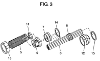
- FIG. 3 is an exploded view of the main portion showing the outline structure of the dustproof and waterproof structure of the joint portion of the robot.
- FIG. 4 is a cross sectional view of a main portion showing the dustproof and waterproof structure near a cable passing hole provided near the joint portion of the robot.
- FIG. 1 is a perspective view showing an outline structure of an industrial robot in accordance with the present embodiment.
- FIG. 2 is a perspective view of a main portion showing an outline structure of a dustproof and waterproof structure of a robot joint portion
- FIG. 3 is an exploded view of the main portion showing the outline structure of the dustproof and waterproof structure of the joint portion.
- FIG. 4 is a cross sectional view of a main portion showing the dustproof and waterproof structure near cable passing holes 4 a and 4 b provided near the joint portion.
- the robot is provided with first arm 1 , second arm 2 and third arm 3 in manipulator 20 .
- Cable passing holes 4 a and 4 b are provided near a joint portion of an outer periphery (an outer surface) of manipulator 20 , and thread portions (not shown) are provided in cable passing holes 4 a and 4 b.
- the thread portions are provided for screwing with a thread portions provided in first connecting member 12 mentioned below.
- Cable protecting pipe 5 is provided along a side surface of second arm 2 .
- electric cables conducting wires or the like
- various filament bodies hereinafter, refer to as “cable bundle”
- a wiring process from first arm 1 to third arm 3 is executed through cable passing holes 4 a and 4 b, as shown in FIG. 1 .
- cable protecting pipe 5 has a function of protecting cable bundle 6 , is constituted, for example, by a metal spring, and is formed approximately in a tubular shape having a spring characteristic and obtained by winding a metal wire in a coil shape.
- cable protecting pipe 5 is not necessarily formed in an accurate tubular shape, but may be approximately formed in a tubular shape.
- Mold guide 7 is provided in an end portion of the cable protecting pipe 5 . At least a part of cable protecting pipe 5 is arranged in an inner side of mold guide 7 , and cable bundle 6 is inserted to an inner portion thereof. In this case, a groove capable of engaging with one end side of cable protecting pipe 5 is formed in an inner side of mold guide 7 , and it is possible to connect cable protecting pipe 5 and mold guide 7 by screwing cable protecting pipe 5 and mold guide 7 . Further, mold guide 7 is formed approximately in a cylindrical shape, is formed, for example, by a resin or the like and may have an elasticity.
- Mold treatment portion 8 is resin filled in an inner side of mold guide 7 for firmly attaching cable protecting pipe 5 and cable bundle 6 with no gap.
- an epoxy resin or the like may be used as the filling resin, or the other materials may be used.
- Cable protecting pipe fixing device 9 is connected to one end side of cable protecting pipe 5 , and cable bundle 6 is inserted to an inner side thereof.
- a groove capable of engaging with one end side of cable protecting pipe 5 is formed in an inner side of cable protecting pipe fixing device 9 , and cable protecting pipe 5 and cable protecting pipe fixing device 9 are connected by screwing cable protecting pipe 5 and cable protecting pipe fixing device 9 .
- Cable protecting pipe fixing device 9 and cable bundle 6 are fixed by a cable fixing device.
- the present embodiment employs binding band 11 as the cable fixing device.
- a hole is provided in the cable protecting pipe fixing device 9 , and cable protecting pipe fixing device 9 and cable bundle 6 are fixed by inserting binding band 11 into the hole of cable protecting pipe fixing device 9 so as to bind cable protecting pipe fixing device 9 and cable bundle 6 .
- First connecting member 12 is provided in cable passing holes 4 a and 4 b. Cable bundle 6 is inserted to an inner side of first connecting member 12 .
- a thread portion is provided in surfaces in both ends of first connecting member 12 , one thread portion is provided for being engaged with cable passing holes 4 a and 4 b, and the other thread portion is provided for being engaged with second connecting member 13 mentioned below.
- Second connecting member 13 is connected to first connecting member 12 , thereby fixing mold guide 7 and cable protecting pipe fixing device 9 .
- Cable bundle 6 is also inserted to an inner side of second connecting member.
- a thread portion capable of engaging with a thread portion provided in first connecting member 12 is formed in a surface in an inner side of the second connecting member.
- first connecting member 12 and second connecting member 13 are connected by screwing first connecting member 12 and second connecting member 13 . Further, mold guide 7 and cable protecting pipe fixing device 9 are fixed by screwing first connecting member 12 and second connecting member 13 , thereby pinching mold guide 7 and cable protecting pipe fixing device 9 by first connecting member 12 and second connecting member 13 .
- a pressure nut can be employed as one example of second connecting member 13 . It is possible to more firmly fix by using the pressure nut, in comparison with the case of using a simple nut.
- First seal member 14 seals a gap between an inner peripheral surface of first connecting member 12 and an outer peripheral surface of mold guide 7 . Further, second seal member 15 seals a gap between first connecting member 12 and cable passing holes 4 a and 4 b.
- a sheet gasket having an elasticity may be used as first seal member 14 and second seal member 15 , and an O-ring, a liquid surface seal member or the like may be alternately used.
- an outer shape of the bundle is not stabilized only by cable bundle 6 without mold guide 7 , and it is very hard to achieve the dustproof and waterproof between the unstable outer shape portion of cable bundle 6 and cable passing holes 4 a and 4 b.
- an outer shape an outer shape of mold guide 7 . Accordingly, it is possible to easily achieve the dustproof and waterproof structure by forming the inner space formed by first connecting member 12 and second connecting member 13 in a shape corresponding to mold guide 7 , and screwing first connecting member 12 and second connecting member 13 .
- the dustproof and waterproof structure constructed by cable passing holes 4 a and 4 b and mold guide 7 is not affected. In other words, it is not necessary to change cable passing holes 4 a and 4 b, and no influence is exerted on the parts relating to the power transmission arranged in the joint shaft or the like.
- mold guide 7 and cable protecting pipe fixing device 9 which are fixed by connecting first connecting member 12 and second connecting member 13 are screwed with cable protecting pipe 5 , and cable bundle 6 and cable protecting pipe 5 which are inserted in the inner side of mold guide 7 are firmly attached in accordance with a mold treatment.
- Cable protecting pipe 5 and cable bundle 6 are rigidly fixed by fixing cable bundle 6 to cable protecting pipe fixing device 9 by binding band 11 serving as the cable fixing device, in addition thereto. Accordingly, it is possible to easily achieve the fixation of the cable wiring portion which is not affected by the rotating motion of the joint shaft.
- mold guide 7 having the determined inner space and the stable seal outer shape is provided, cable bundle 6 is passed to the inner side of mold guide 7 , and the mold treatment is applied by mold treatment portion 8 .
- the seal treatment is applied to the outer side of mold guide 7 , and cable protecting pipe fixing device 9 screwed with cable protecting pipe 5 , and cable bundle 6 are fixed by binding band 11 serving as the cable fixing device.
- the dustproof and waterproof structure on the basis of the simple structure without complicating the joint portion structure by setting the hollow space coaxially with the joint shaft of the manipulator, as is different from the conventional robot dustproof and waterproof structure. Further, since the joint portion is neither enlarged in size nor increased in weight by employing the dustproof and waterproof structure as is different from the conventional robot, the motion performance of the robot is not adversely affected.
- the present embodiment exemplifies cable bundle 6 constituted by a plurality of filament bodies, however, the number of the filament bodies is not limited, but may be set to one or plural number.
- the present invention it is possible to achieve the waterproof and dustproof structure of the joint portion of the robot on the basis of the simple structure, and it is possible to easily correspond to the change of the numerical quantity and the magnitude in accordance with the specification change of the cable bundle without exerting an influence on the power transmission system parts or the like arranged in the joint shaft. Therefore, the present invention is very useful as the joint portion structure and the cable wiring process of the industrial robot.
Landscapes
- Engineering & Computer Science (AREA)
- Architecture (AREA)
- Civil Engineering (AREA)
- Structural Engineering (AREA)
- Robotics (AREA)
- Mechanical Engineering (AREA)
- Manipulator (AREA)
- Forklifts And Lifting Vehicles (AREA)
Abstract
Description
- 1 first arm
- 2 second arm
- 3 third arm
- 4 a, 4 b cable passing hole
- 5 cable protecting pipe
- 6 cable bundle
- 7 mold guide
- 8 mold treatment portion
- 9 cable protecting pipe fixing device
- 11 binding band (cable fixing device)
- 12 first connecting member
- 13 second connecting member
- 14 first seal member
- 15 second seal member
- 20 manipulator
Claims (21)
Applications Claiming Priority (3)
| Application Number | Priority Date | Filing Date | Title |
|---|---|---|---|
| JP2006280068 | 2006-10-13 | ||
| JP2006-280068 | 2006-10-13 | ||
| PCT/JP2007/056154 WO2008044348A1 (en) | 2006-10-13 | 2007-03-26 | Industrial robot |
Publications (2)
| Publication Number | Publication Date |
|---|---|
| US20090249915A1 US20090249915A1 (en) | 2009-10-08 |
| US7806019B2 true US7806019B2 (en) | 2010-10-05 |
Family
ID=39243615
Family Applications (1)
| Application Number | Title | Priority Date | Filing Date |
|---|---|---|---|
| US11/792,381 Active 2029-05-24 US7806019B2 (en) | 2006-10-13 | 2007-03-26 | Industrial robot |
Country Status (7)
| Country | Link |
|---|---|
| US (1) | US7806019B2 (en) |
| EP (1) | EP1950011B1 (en) |
| JP (1) | JP4055826B1 (en) |
| CN (1) | CN101309784B (en) |
| AT (1) | ATE455626T1 (en) |
| DE (1) | DE602007004430D1 (en) |
| WO (1) | WO2008044348A1 (en) |
Cited By (9)
| Publication number | Priority date | Publication date | Assignee | Title |
|---|---|---|---|---|
| US20100175495A1 (en) * | 2009-01-09 | 2010-07-15 | Hong Fu Jin Precision Industry(Shenzhen) Co., Ltd. | Manipulator |
| US20110072930A1 (en) * | 2009-09-29 | 2011-03-31 | Kuka Roboter Gmbh | Industrial Robot With A Weight Counterbalance System |
| US20110203402A1 (en) * | 2008-11-04 | 2011-08-25 | Abb Technology Ab | Process turning disc, a robot arm comprising a process turning disc, a robot and a use of a process turning disc |
| US20110252915A1 (en) * | 2010-04-14 | 2011-10-20 | Kabushiki Kaisha Kobe Seiko Sho | Industrial robot |
| US20130255817A1 (en) * | 2012-03-27 | 2013-10-03 | Fanuc Corporation | Umbilical member treatment device |
| US20140053676A1 (en) * | 2012-08-23 | 2014-02-27 | Michael Sussman | Robotic power and signal distribution using laminated cable with separator webs |
| US20150040713A1 (en) * | 2013-08-09 | 2015-02-12 | Yamaha Hatsudoki Kabushiki Kaisha | Wiring structure for robot arm |
| US20180009117A1 (en) * | 2015-01-21 | 2018-01-11 | Kawasaki Jukogyo Kabushiki Kaisha | Industrial robot |
| US10632629B2 (en) * | 2015-06-09 | 2020-04-28 | Kuka Deutschland Gmbh | Cable device of an industrial robot |
Families Citing this family (19)
| Publication number | Priority date | Publication date | Assignee | Title |
|---|---|---|---|---|
| SE0303539D0 (en) * | 2003-12-22 | 2003-12-22 | Abb Ab | Device for an industrial robot |
| CN102079094B (en) * | 2009-11-26 | 2013-11-06 | 鸿富锦精密工业(深圳)有限公司 | Robot structure |
| JP5507450B2 (en) * | 2008-05-09 | 2014-05-28 | 川崎重工業株式会社 | Article transport robot |
| CN102114629B (en) * | 2009-12-30 | 2014-06-25 | 鸿富锦精密工业(深圳)有限公司 | Robot structure |
| CN103056877B (en) * | 2011-10-21 | 2015-07-29 | 鸿富锦精密工业(深圳)有限公司 | Manipulator |
| JP2013212560A (en) * | 2012-04-02 | 2013-10-17 | Seiko Epson Corp | Robot system and robot |
| JP5884785B2 (en) * | 2013-07-30 | 2016-03-15 | 株式会社安川電機 | robot |
| DE102014225288A1 (en) * | 2014-12-09 | 2016-06-09 | Zf Friedrichshafen Ag | Roll stabilization system for a motor vehicle |
| JP5975129B1 (en) | 2015-03-02 | 2016-08-23 | 株式会社安川電機 | robot |
| JP6582520B2 (en) * | 2015-04-28 | 2019-10-02 | セイコーエプソン株式会社 | robot |
| JP6441254B2 (en) * | 2016-04-05 | 2018-12-19 | ファナック株式会社 | Robot striatum processing structure |
| DE102016206921A1 (en) * | 2016-04-22 | 2017-10-26 | Kuka Roboter Gmbh | Robotic arm with a connection socket for a supply line |
| CN106671126B (en) * | 2017-01-04 | 2019-01-18 | 南京航空航天大学 | Based on hollow ultrasound electric machine and with the robot wrist of bracket and bi-bellow |
| CN106695867B (en) * | 2017-01-04 | 2019-01-18 | 南京航空航天大学 | Based on hollow ultrasound electric machine and with the robot wrist of bracket and bellows |
| JP2019048360A (en) * | 2017-09-12 | 2019-03-28 | セイコーエプソン株式会社 | Robot and robot system |
| JP6985309B2 (en) * | 2019-01-24 | 2021-12-22 | ファナック株式会社 | Striatum processing structure of robot and fixing member for striatum expansion |
| JP7160765B2 (en) * | 2019-07-08 | 2022-10-25 | 株式会社神戸製鋼所 | Ceiling-mounted industrial robot |
| CN111618909A (en) * | 2020-05-29 | 2020-09-04 | 羊泰丞 | Industrial automatic mechanical arm control system |
| JPWO2023026434A1 (en) | 2021-08-26 | 2023-03-02 |
Citations (8)
| Publication number | Priority date | Publication date | Assignee | Title |
|---|---|---|---|---|
| DE1911652A1 (en) | 1969-03-07 | 1970-09-17 | Lapp Kg U I | Screwed cable gland packing with pressure - relief |
| US4797513A (en) | 1987-11-25 | 1989-01-10 | Yazaki Corporation | Grommet with wires sealed thereto and method of forming same |
| JPH0857793A (en) | 1994-08-17 | 1996-03-05 | Toshiba Corp | Industrial robot |
| JPH09109085A (en) | 1995-10-11 | 1997-04-28 | Shibaura Eng Works Co Ltd | Cable in-and-out member |
| JPH11254377A (en) | 1998-03-10 | 1999-09-21 | Denso Corp | Robot |
| JPH11277481A (en) | 1998-03-27 | 1999-10-12 | Mitsubishi Heavy Ind Ltd | Industrial motor-driven robot |
| WO2000025992A1 (en) | 1998-10-16 | 2000-05-11 | Abb Ab | Industrial robot and cable guiding device for this robot and use of the device |
| JP2004358601A (en) | 2003-06-04 | 2004-12-24 | Hitachi High-Technologies Corp | Micro-hand |
Family Cites Families (1)
| Publication number | Priority date | Publication date | Assignee | Title |
|---|---|---|---|---|
| JP4193632B2 (en) * | 2003-02-04 | 2008-12-10 | コニカミノルタホールディングス株式会社 | Toner manufacturing method |
-
2007
- 2007-03-26 CN CN200780000029.8A patent/CN101309784B/en not_active Expired - Fee Related
- 2007-03-26 US US11/792,381 patent/US7806019B2/en active Active
- 2007-03-26 EP EP07717671A patent/EP1950011B1/en not_active Not-in-force
- 2007-03-26 WO PCT/JP2007/056154 patent/WO2008044348A1/en active Application Filing
- 2007-03-26 JP JP2007523910A patent/JP4055826B1/en not_active Expired - Fee Related
- 2007-03-26 DE DE602007004430T patent/DE602007004430D1/en active Active
- 2007-03-26 AT AT07717671T patent/ATE455626T1/en not_active IP Right Cessation
Patent Citations (10)
| Publication number | Priority date | Publication date | Assignee | Title |
|---|---|---|---|---|
| DE1911652A1 (en) | 1969-03-07 | 1970-09-17 | Lapp Kg U I | Screwed cable gland packing with pressure - relief |
| US4797513A (en) | 1987-11-25 | 1989-01-10 | Yazaki Corporation | Grommet with wires sealed thereto and method of forming same |
| JPH0857793A (en) | 1994-08-17 | 1996-03-05 | Toshiba Corp | Industrial robot |
| JPH09109085A (en) | 1995-10-11 | 1997-04-28 | Shibaura Eng Works Co Ltd | Cable in-and-out member |
| JPH11254377A (en) | 1998-03-10 | 1999-09-21 | Denso Corp | Robot |
| JPH11277481A (en) | 1998-03-27 | 1999-10-12 | Mitsubishi Heavy Ind Ltd | Industrial motor-driven robot |
| WO2000025992A1 (en) | 1998-10-16 | 2000-05-11 | Abb Ab | Industrial robot and cable guiding device for this robot and use of the device |
| JP2002528287A (en) | 1998-10-16 | 2002-09-03 | エービービー エービー | Industrial robot, cable guiding device for the robot and use of the device |
| US6622585B1 (en) | 1998-10-16 | 2003-09-23 | Abb Ab | Industrial robot and cable guiding device for this robot and use of the device |
| JP2004358601A (en) | 2003-06-04 | 2004-12-24 | Hitachi High-Technologies Corp | Micro-hand |
Non-Patent Citations (1)
| Title |
|---|
| Supplementary European Search Report issued Jan. 8, 2009 in EP 07 71 7671, which is a foreign counterpart to the present application. |
Cited By (17)
| Publication number | Priority date | Publication date | Assignee | Title |
|---|---|---|---|---|
| US20110203402A1 (en) * | 2008-11-04 | 2011-08-25 | Abb Technology Ab | Process turning disc, a robot arm comprising a process turning disc, a robot and a use of a process turning disc |
| US8627741B2 (en) * | 2008-11-04 | 2014-01-14 | Abb Technology Ab | Process turning disc, a robot arm comprising a process turning disc, a robot and a use of a process turning disc |
| US8245592B2 (en) * | 2009-01-09 | 2012-08-21 | Hong Fu Jin Precision Industry (Shenzhen) Co., Ltd. | Manipulator |
| US20100175495A1 (en) * | 2009-01-09 | 2010-07-15 | Hong Fu Jin Precision Industry(Shenzhen) Co., Ltd. | Manipulator |
| US10987817B2 (en) * | 2009-09-29 | 2021-04-27 | Kuka Deutschland Gmbh | Industrial robot with a weight counterbalance system |
| US20110072930A1 (en) * | 2009-09-29 | 2011-03-31 | Kuka Roboter Gmbh | Industrial Robot With A Weight Counterbalance System |
| US20110252915A1 (en) * | 2010-04-14 | 2011-10-20 | Kabushiki Kaisha Kobe Seiko Sho | Industrial robot |
| US8631720B2 (en) * | 2010-04-14 | 2014-01-21 | Daihen Corporation | Industrial robot |
| US20130255817A1 (en) * | 2012-03-27 | 2013-10-03 | Fanuc Corporation | Umbilical member treatment device |
| US8863607B2 (en) * | 2012-03-27 | 2014-10-21 | Fanuc Corporation | Umbilical member treatment device |
| US20140053676A1 (en) * | 2012-08-23 | 2014-02-27 | Michael Sussman | Robotic power and signal distribution using laminated cable with separator webs |
| US9579806B2 (en) * | 2012-08-23 | 2017-02-28 | Rethink Robotics, Inc. | Robotic power and signal distribution using laminated cable with separator webs |
| US10293496B2 (en) * | 2012-08-23 | 2019-05-21 | Rethink Robotics Gmbh | Robotic power and signal distribution using laminated cable with separator webs |
| US10160120B2 (en) * | 2013-08-09 | 2018-12-25 | Yamaha Hatsudoki Kabushiki Kaisha | Wiring structure for robot arm |
| US20150040713A1 (en) * | 2013-08-09 | 2015-02-12 | Yamaha Hatsudoki Kabushiki Kaisha | Wiring structure for robot arm |
| US20180009117A1 (en) * | 2015-01-21 | 2018-01-11 | Kawasaki Jukogyo Kabushiki Kaisha | Industrial robot |
| US10632629B2 (en) * | 2015-06-09 | 2020-04-28 | Kuka Deutschland Gmbh | Cable device of an industrial robot |
Also Published As
| Publication number | Publication date |
|---|---|
| US20090249915A1 (en) | 2009-10-08 |
| WO2008044348A1 (en) | 2008-04-17 |
| CN101309784B (en) | 2010-06-09 |
| CN101309784A (en) | 2008-11-19 |
| JP4055826B1 (en) | 2008-03-05 |
| EP1950011A1 (en) | 2008-07-30 |
| EP1950011B1 (en) | 2010-01-20 |
| DE602007004430D1 (en) | 2010-03-11 |
| ATE455626T1 (en) | 2010-02-15 |
| JPWO2008044348A1 (en) | 2010-02-04 |
| EP1950011A4 (en) | 2009-02-04 |
Similar Documents
| Publication | Publication Date | Title |
|---|---|---|
| US7806019B2 (en) | Industrial robot | |
| JP2006289589A (en) | Industrial robot | |
| CN104245249B (en) | Robot joint construction | |
| US7765890B2 (en) | Industrial robot | |
| US7631573B2 (en) | Guiding device for an umbilical member of a robot and a robot having the guiding device | |
| US8893577B2 (en) | Umbilical member arrangement unit of robot arm section | |
| EP1491300A1 (en) | Connection of a robot mechanical unit and a control unit | |
| US20050103148A1 (en) | Cable distribution and support equipment for sensor in robot system | |
| US11904460B2 (en) | Robot linear-object unit and linear-object routing method | |
| CN108883540B (en) | Robot | |
| JPH09150388A (en) | Directly driven robot | |
| CN108883531B (en) | Robot | |
| JP2016203331A (en) | robot | |
| US20210054956A1 (en) | Termination for Sheathed Tubing with Leak Containment and Detection Provisions | |
| US10742006B1 (en) | Cable fixation structure | |
| US11518049B2 (en) | Rotary module and robot | |
| CN111065829B (en) | Strip member assembly | |
| JP4810989B2 (en) | Reducer integrated actuator | |
| JP7225640B2 (en) | Encoders, drives and robots | |
| EP4238722A1 (en) | Bending operation mechanism | |
| JP2541250Y2 (en) | connector | |
| KR101000847B1 (en) | Remote driveline | |
| JP2003266360A (en) | Scalar type robot | |
| TW201213684A (en) | Multi spindle gear box structure |
Legal Events
| Date | Code | Title | Description |
|---|---|---|---|
| AS | Assignment |
Owner name: MATSUSHITA ELECTRIC INDUSTRIAL CO., LTD., JAPAN Free format text: ASSIGNMENT OF ASSIGNORS INTEREST;ASSIGNORS:IWAI, SEIJI;SUZUKI, SHIAKI;REEL/FRAME:021366/0768 Effective date: 20070521 |
|
| AS | Assignment |
Owner name: PANASONIC CORPORATION,JAPAN Free format text: CHANGE OF NAME;ASSIGNOR:MATSUSHITA ELECTRIC INDUSTRIAL CO., LTD.;REEL/FRAME:021818/0725 Effective date: 20081001 Owner name: PANASONIC CORPORATION, JAPAN Free format text: CHANGE OF NAME;ASSIGNOR:MATSUSHITA ELECTRIC INDUSTRIAL CO., LTD.;REEL/FRAME:021818/0725 Effective date: 20081001 |
|
| STCF | Information on status: patent grant |
Free format text: PATENTED CASE |
|
| FEPP | Fee payment procedure |
Free format text: PAYOR NUMBER ASSIGNED (ORIGINAL EVENT CODE: ASPN); ENTITY STATUS OF PATENT OWNER: LARGE ENTITY |
|
| FPAY | Fee payment |
Year of fee payment: 4 |
|
| MAFP | Maintenance fee payment |
Free format text: PAYMENT OF MAINTENANCE FEE, 8TH YEAR, LARGE ENTITY (ORIGINAL EVENT CODE: M1552) Year of fee payment: 8 |
|
| MAFP | Maintenance fee payment |
Free format text: PAYMENT OF MAINTENANCE FEE, 12TH YEAR, LARGE ENTITY (ORIGINAL EVENT CODE: M1553); ENTITY STATUS OF PATENT OWNER: LARGE ENTITY Year of fee payment: 12 |