US7802816B2 - Control arm support brackets and vehicles using same - Google Patents

Control arm support brackets and vehicles using same Download PDF

Info

Publication number
US7802816B2
US7802816B2 US12/127,048 US12704808A US7802816B2 US 7802816 B2 US7802816 B2 US 7802816B2 US 12704808 A US12704808 A US 12704808A US 7802816 B2 US7802816 B2 US 7802816B2
Authority
US
United States
Prior art keywords
control arm
pair
arm support
recesses
frame
Prior art date
Legal status (The legal status is an assumption and is not a legal conclusion. Google has not performed a legal analysis and makes no representation as to the accuracy of the status listed.)
Expired - Fee Related, expires
Application number
US12/127,048
Other versions
US20090294199A1 (en
Inventor
Jeremy T. McGuire
Current Assignee (The listed assignees may be inaccurate. Google has not performed a legal analysis and makes no representation or warranty as to the accuracy of the list.)
Honda Motor Co Ltd
Original Assignee
Honda Motor Co Ltd
Priority date (The priority date is an assumption and is not a legal conclusion. Google has not performed a legal analysis and makes no representation as to the accuracy of the date listed.)
Filing date
Publication date
Application filed by Honda Motor Co Ltd filed Critical Honda Motor Co Ltd
Priority to US12/127,048 priority Critical patent/US7802816B2/en
Assigned to HONDA MOTOR COMPANY LTD. reassignment HONDA MOTOR COMPANY LTD. ASSIGNMENT OF ASSIGNORS INTEREST (SEE DOCUMENT FOR DETAILS). Assignors: MCGUIRE, JEREMY T.
Publication of US20090294199A1 publication Critical patent/US20090294199A1/en
Application granted granted Critical
Publication of US7802816B2 publication Critical patent/US7802816B2/en
Expired - Fee Related legal-status Critical Current
Adjusted expiration legal-status Critical

Links

Images

Classifications

    • BPERFORMING OPERATIONS; TRANSPORTING
    • B60VEHICLES IN GENERAL
    • B60GVEHICLE SUSPENSION ARRANGEMENTS
    • B60G7/00Pivoted suspension arms; Accessories thereof
    • B60G7/008Attaching arms to unsprung part of vehicle
    • BPERFORMING OPERATIONS; TRANSPORTING
    • B60VEHICLES IN GENERAL
    • B60GVEHICLE SUSPENSION ARRANGEMENTS
    • B60G2200/00Indexing codes relating to suspension types
    • B60G2200/10Independent suspensions
    • B60G2200/14Independent suspensions with lateral arms
    • B60G2200/142Independent suspensions with lateral arms with a single lateral arm, e.g. MacPherson type
    • BPERFORMING OPERATIONS; TRANSPORTING
    • B60VEHICLES IN GENERAL
    • B60GVEHICLE SUSPENSION ARRANGEMENTS
    • B60G2200/00Indexing codes relating to suspension types
    • B60G2200/30Rigid axle suspensions
    • B60G2200/31Rigid axle suspensions with two trailing arms rigidly connected to the axle
    • BPERFORMING OPERATIONS; TRANSPORTING
    • B60VEHICLES IN GENERAL
    • B60GVEHICLE SUSPENSION ARRANGEMENTS
    • B60G2202/00Indexing codes relating to the type of spring, damper or actuator
    • B60G2202/10Type of spring
    • B60G2202/11Leaf spring
    • B60G2202/112Leaf spring longitudinally arranged
    • BPERFORMING OPERATIONS; TRANSPORTING
    • B60VEHICLES IN GENERAL
    • B60GVEHICLE SUSPENSION ARRANGEMENTS
    • B60G2202/00Indexing codes relating to the type of spring, damper or actuator
    • B60G2202/10Type of spring
    • B60G2202/12Wound spring
    • BPERFORMING OPERATIONS; TRANSPORTING
    • B60VEHICLES IN GENERAL
    • B60GVEHICLE SUSPENSION ARRANGEMENTS
    • B60G2204/00Indexing codes related to suspensions per se or to auxiliary parts
    • B60G2204/40Auxiliary suspension parts; Adjustment of suspensions
    • B60G2204/43Fittings, brackets or knuckles
    • B60G2204/4302Fittings, brackets or knuckles for fixing suspension arm on the vehicle body or chassis
    • BPERFORMING OPERATIONS; TRANSPORTING
    • B60VEHICLES IN GENERAL
    • B60GVEHICLE SUSPENSION ARRANGEMENTS
    • B60G2206/00Indexing codes related to the manufacturing of suspensions: constructional features, the materials used, procedures or tools
    • B60G2206/01Constructional features of suspension elements, e.g. arms, dampers, springs
    • B60G2206/60Subframe construction
    • BPERFORMING OPERATIONS; TRANSPORTING
    • B60VEHICLES IN GENERAL
    • B60GVEHICLE SUSPENSION ARRANGEMENTS
    • B60G2300/00Indexing codes relating to the type of vehicle
    • B60G2300/13Small sized city motor vehicles
    • YGENERAL TAGGING OF NEW TECHNOLOGICAL DEVELOPMENTS; GENERAL TAGGING OF CROSS-SECTIONAL TECHNOLOGIES SPANNING OVER SEVERAL SECTIONS OF THE IPC; TECHNICAL SUBJECTS COVERED BY FORMER USPC CROSS-REFERENCE ART COLLECTIONS [XRACs] AND DIGESTS
    • Y10TECHNICAL SUBJECTS COVERED BY FORMER USPC
    • Y10STECHNICAL SUBJECTS COVERED BY FORMER USPC CROSS-REFERENCE ART COLLECTIONS [XRACs] AND DIGESTS
    • Y10S180/00Motor vehicles
    • Y10S180/908Motor vehicles with short wheelbase

Definitions

  • FIG. 4 is an exploded front perspective view of a front end of the frame assembly of FIG. 2 depicting left and right control arms and left and right cushions in association with the first and second control arm support brackets;
  • right and left suspension support members 70 , 80 can have any of a variety of configurations to facilitate securement of left and right cushions 60 , 62 to a frame.
  • the right and left suspension support members 70 , 80 can be integrally formed from one-piece construction.
  • the right and left cushions 60 , 62 are shown to include hydraulic suspension members, any of a variety of suitable alternative cushion configurations can be provided (e.g., a spring, a linear electromagnetic motor).
  • the first and second control arm support brackets 30 , 50 and the left and right suspension support members 70 , 80 can be coupled with the frame 20 in substantially the same location.
  • the control arm support brackets 30 , 50 are shown in FIG. 3 to respectively define a first pair of recesses 36 and a second pair of recesses 56 .
  • the recesses 36 , 56 can correspond with the left and right suspension support members 70 , 80 such that, when the control arm support brackets 30 , 50 are coupled with the frame 20 , the left and right suspension support members 70 , 80 are at least partially disposed in the recesses 36 , 56 .

Landscapes

  • Engineering & Computer Science (AREA)
  • Mechanical Engineering (AREA)
  • Body Structure For Vehicles (AREA)

Abstract

A vehicular frame assembly is provided and includes a pair of control arm support brackets. Each of the control arm support brackets define a pair of recesses. The first control arm support bracket and the second control arm support bracket are substantially identical and are configured to be positioned along a vehicular frame such that one of the pairs of recesses defined by a control arm support bracket receives forward legs of right and left suspension support members and the other of the pairs of recesses defined by the other of the control arm support bracket receives rearward legs of right and left suspension support members. A vehicle is also provided.

Description

TECHNICAL FIELD
The inventive principles generally relate to control arm support brackets provided on a vehicle to pivotally support a control arm.
BACKGROUND
A pair of control arm support brackets can be provided on a vehicle to pivotally support a control arm with respect to a frame of the vehicle. Suspension support members can also be provided on a vehicle to support cushions. Conventionally, the suspension support members are coupled with the frame at substantially the same location as the control arm support brackets. Each control arm support bracket is typically uniquely configured according to the location of the control arm support brackets with respect to the suspension support members.
SUMMARY
A vehicular frame assembly is provided. The vehicular frame assembly can comprise a frame, a left suspension support member, a right suspension support member, a first control arm support bracket, and a second control arm support bracket. The frame is intersected by an imaginary plane which bisects the frame into left and right sides. The left suspension support member is coupled with the left side of the frame and comprises a left forward leg and a left rearward leg. The right suspension support member is coupled with the right side of the frame and comprises a right forward leg and a right rearward leg. The first control arm support bracket defines a first pair of recesses and is secured to the frame in a first orientation such that the left forward leg of the left suspension support member is at least partially disposed within one recess of the first pair of recesses and the right forward leg of the right suspension support member is at least partially disposed within the other recess of the first pair of recesses. The second control arm support bracket defines a second pair of recesses and is secured to the frame in a second orientation such that the left rearward leg of the left suspension support member is at least partially disposed within one recess of the second pair of recesses and the right rearward leg of the right suspension support member is at least partially disposed within the other recess of the second pair of recesses. The first and second control arm support brackets are substantially identical.
A vehicular frame assembly is also provided. The vehicular frame assembly comprises a first control arm support bracket and a second control arm support bracket. The first control arm support bracket comprises a first end, a second end, a sidewall, an upper portion and a lower portion. The first control arm support bracket defines a first pair of recesses. The first pair of recesses is at least partially defined by the sidewall and extends between the upper portion of the first control arm support bracket and the lower portion of the first control arm support bracket. The second control arm support bracket comprises a first end, a second end, a sidewall, an upper portion and a lower portion. The second control arm support bracket defines a second pair of recesses. The second pair of recesses is at least partially defined by the sidewall and extends between the upper portion of the second control arm support bracket and the lower portion of the second control arm support bracket. The control arm support bracket and the second control arm support bracket are substantially identical. The control arm support bracket and the second control arm support bracket are configured to be positioned along a vehicular frame such that one of the first or second pairs of recesses receives forward legs of right and left suspension support members and the other of the first pair or second pair of recesses receives rearward legs of right and left suspension support members.
A method for assembling a vehicular frame assembly is provided. The method comprises providing a vehicular frame, the vehicular frame being intersected by an imaginary plane which bisects the frame into left and right sides. The method further comprises securing left and right suspension supports to the vehicular frame. The left suspension support comprises a left forward leg and a left rearward leg. The right suspension support comprises a right forward leg and a right rearward leg. The method further comprises providing a pair of substantially identical control arm support brackets. Each control arm support bracket comprises a first end, a second end, and a sidewall at least partially defining a pair of U-shaped recesses. The method further comprises arranging the pair of control arm support brackets in differing orientations along the vehicular frame such the left and right forward legs are at least partially disposed within one pair of recesses and the left and right rearward legs are at least partially disposed within the other pair of recesses.
A vehicular frame assembly is provided. The vehicular frame assembly comprises a frame, a left suspension support member, a right suspension support member, and a pair of control arm support brackets. The frame is intersected by an imaginary plane which bisects the frame into left and right sides. The left suspension support member is coupled with the left side of the frame and comprises a left forward leg and a left rearward leg. The right suspension support member is coupled with the right side of the frame and comprises a right forward leg and a right rearward leg. Each control arm support bracket defines a pair of recesses. One of the control arm support brackets is secured to the frame in a first orientation such that the left forward leg of the left suspension support member and the right forward leg of the right suspension support member are at least partially disposed within respective ones of the pair of recesses defined by the one control arm support bracket. The other of the control arm support brackets is secured to the frame in a second orientation such that the left rearward leg of the left suspension support member and the right rearward leg of the right suspension support member are at least partially disposed within respective ones of the pair of recesses defined by the other control arm support bracket. The control arm support brackets are substantially identical to facilitate arrangement of each control arm support bracket in either the first orientation or the second orientation.
BRIEF DESCRIPTION OF THE DRAWINGS
While the specification concludes with claims particularly pointing out and distinctly claiming the present invention, it is believed that the same will be better understood from the following description taken in conjunction with the accompanying drawings in which:
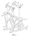
FIG. 1 is an elevated front perspective view depicting a utility vehicle (“UTV”) in accordance with one embodiment;
FIG. 2 is an elevated front perspective view of a frame assembly of the vehicle of FIG. 1;
FIG. 3 is an exploded front perspective view of a front end of the frame assembly of FIG. 2 depicting first and second control arm support brackets wherein certain other components have been removed for clarity of illustration;
FIG. 4 is an exploded front perspective view of a front end of the frame assembly of FIG. 2 depicting left and right control arms and left and right cushions in association with the first and second control arm support brackets;
FIG. 5 is a front perspective view of the components of FIG. 4 as assembled; and
FIG. 6 is a perspective view of the first and second control arm support brackets of FIG. 4 apart from the remaining components of FIG. 4.
DETAILED DESCRIPTION
A vehicle and its operation are hereinafter described in detail in connection with the views and examples of FIGS. 1-6, wherein like numbers indicate the same or corresponding elements throughout the views. FIG. 1 shows a vehicle 10 which can incorporate a frame assembly (e.g., 12 in FIGS. 2-6). The vehicle 10 is shown in FIG. 1 to be a utility vehicle (“UTV”). However, other vehicles can be provided, such as, for example, an automobile, a truck, a van, a recreational vehicle, an all terrain vehicle, agricultural equipment, or construction equipment. Though the vehicle 10 is shown to be of a type having four wheels (e.g., 11), it will be appreciated that other vehicles can alternatively include more than four wheels or less than four wheels.
The vehicle 10 can include and extend between front and rear ends 14, 16 as shown in FIG. 1. As illustrated in FIGS. 2-5, the vehicle 10 can include a frame assembly 12 which can extend between the front end 14 and the rear end 16 of the vehicle 10. The frame assembly 12 can include a frame 20. The frame 20 is shown in FIGS. 2-5 to be a rail-type frame that includes a left frame rail 22 and a right frame rail 24, each extending between the front end 14 and the rear end 16 of the vehicle 10. The frame 20 is shown to be bisected into left and right sides by an imaginary plane, P, and the left and right frame rails 22, 24 are shown to be disposed on opposite sides of the frame. It will be appreciated that, although the left and right frame rails 22, 24 are shown to be formed of a tubular construction, a frame can be formed from box rails, stamped sheet metal components, or any of a variety of alternative configurations. It will also be appreciated that a frame can be provided in any of a variety of alternative arrangements such as an integrated, uni-body construction.
As is common, the frame 20 can support any of a variety of vehicular components. For example, the vehicle 10 can comprise a bed 18 supported by the frame 20. The bed 18 can facilitate support of cargo for transportation by the vehicle 10. Although the bed 18 is shown in FIG. 1 to include sides to facilitate support of loose cargo (e.g., dirt), it will be appreciated that the bed 18 can be configured in any of a variety of suitable alternative arrangements (e.g., as a flat bed) for carrying cargo. It will also be appreciated that, in lieu of a bed, a vehicle can include a cargo rack, a pump unit, a digging implement, a towing platform, a crane, or any of a variety of other implements.
Left and right control arms 26, 28 can be pivotally supported along the frame 20 to facilitate support of wheels 11 with respect to the frame 20. The left and right control arms 26, 28 are shown in FIG. 2 to be pivotally supported along the frame 20 by first and second control arm support brackets 30, 50. In one embodiment, and as illustrated in FIGS. 3-5, the first control arm support bracket 30 can be an elongate member extending between a left end 32 and a right end 34 and having a substantially polygonal cross-section. Similarly, the second control arm support bracket 50 can be an elongate member extending between a left end 52 and a right end 54 and having a substantially polygonal cross-section. However, it will be appreciated that the first and second control arm support bracket 30, 50 can be any of a variety of configurations that facilitate support of control arms with respect to a frame. For example, a first and second control arm support bracket can each be formed from U-channel construction.
The first and second control arm support brackets 30, 50 can be configured to pivotally support one or more control arms (e.g., 26, 28). In one embodiment as shown in FIGS. 2-5, the first and second control arm support brackets 30, 50 can define channeled portions along each of the left ends 32, 52 and the right ends 34, 54. The first and second control arm support brackets 30, 50 can cooperate to support each of the left and right control arms 26, 28. For example, portions of the left control arm 26 is shown in FIG. 5 to be disposed within the channeled portions of the left ends 32, 52 of the first and second control arm support brackets 30, 50 and pivotally supported with bolts 99. Similarly, portions of the right control arm 28 is shown to be disposed within the channeled portions of the right ends 34, 54 of the first and second control arm support brackets 30, 50 and pivotally supported with bolts 99. It will be appreciated that ends of first and second support brackets can pivotally support control arms in any of a variety of alternative arrangements (e.g., ball and socket). Furthermore, although the control arms 26, 28 are illustrated in an A-arm configuration, it will be appreciated a control arm can be provided in any of a variety of configurations (e.g., elongate, L-shaped).
As is common, a cushion, such as a shock or strut, can be supported between a control arm (e.g., 26, 28) and the frame 20 to dampen sudden movement of the control arm with respect to the frame 20 during vehicle travel. As illustrated in FIG. 2, a left suspension support member 70 can be secured with the left frame rail 22 and a right suspension support member 80 can be secured with the right frame rail 24. A left cushion 60 is shown to be supported between the left control arm 26 and the left suspension support member 70. Similarly, a right cushion 62 is shown to be supported between the right control arm 28 and the right suspension support member 80. The right and left suspension support members 70, 80 are shown to be respectively formed from tubular construction. However, it will be appreciated that right and left suspension support members 70, 80 can have any of a variety of configurations to facilitate securement of left and right cushions 60, 62 to a frame. For example, the right and left suspension support members 70, 80 can be integrally formed from one-piece construction. It will also be appreciated that while the right and left cushions 60, 62 are shown to include hydraulic suspension members, any of a variety of suitable alternative cushion configurations can be provided (e.g., a spring, a linear electromagnetic motor).
It will be appreciated from FIGS. 2-5 that to support the left and right control arms 26, 28 adjacent to the left and right suspension support members 70, 80, the first and second control arm support brackets 30, 50 and the left and right suspension support members 70, 80 can be coupled with the frame 20 in substantially the same location. The control arm support brackets 30, 50 are shown in FIG. 3 to respectively define a first pair of recesses 36 and a second pair of recesses 56. The recesses 36, 56 can correspond with the left and right suspension support members 70, 80 such that, when the control arm support brackets 30, 50 are coupled with the frame 20, the left and right suspension support members 70, 80 are at least partially disposed in the recesses 36, 56. For example, with reference to FIGS. 2 and 3, the first control arm support bracket 30 is shown to be in a first orientation such that a left forward leg 72 of the left suspension support member 70 is partially disposed within one recess 36 and a right forward leg 82 of the right suspension support member 80 is partially disposed within the other recess 36. Additionally, the second control arm support bracket 50 is shown in a second orientation such that a left rearward leg 74 of the left suspension support member 70 is partially disposed within one recess 56 and a right rearward leg 84 of the right suspension support member 80 is partially disposed within the other recess 56.
The recesses 36, 56 are shown in FIGS. 2-6 to be generally U-shaped and defined by respective sidewalls (e.g., 38, 58) of the first and second control arm support brackets 30, 50. It will be appreciated, however, that recesses can have any of a variety of shapes or configurations to facilitate securement of the first and second control arm support brackets 30, 50 and the left and right suspension support members 70, 80 in substantially the same location. For example, recesses can be defined by upper and lower portions of the first and second control arm support brackets 30, 50 such that a passage is formed therethrough. Furthermore, it will be appreciated that the recesses can be provided along first and second support brackets in any of a variety of locations to correspond with respective suspension support members provided on a frame.
Although the first control arm support bracket 30 and the second control arm support bracket 50 are shown in FIGS. 2-5 to be arranged such that recesses 36 face away from recesses 56, it will be appreciated that first and second support brackets can be coupled with a frame 20 in any of a variety of orientations. For example, a first control arm support bracket and a second control arm support bracket can be arranged along a frame such that each pair of recesses faces the front end 14 of the vehicle 10. In another example, a first control arm support bracket and a second control arm support bracket can be arranged along a frame such that each pair of recesses faces the rear end 16 of the vehicle 10. In yet another example, a first control arm support bracket and a second control arm support bracket can be arranged along a frame such that each pair of recesses faces one another.
It will be appreciated that left and right control arms, 26, 28, left and right suspension support members 70, 80, and first and second control arm support brackets 30, 50 can support wheels (e.g., 11) along a vehicle in any of a variety of arrangements. For example, in one alternative embodiment, left and right control arms, left and right suspension support members, and first and second control arm support brackets can be provided along a rear of a vehicle to support rear wheels with respect to a frame.
It will be appreciated that the first control arm support bracket 30 and the second control arm support bracket 50 can be substantially identical. In one embodiment as illustrated in FIG. 6, each of the first and second control arm support brackets 30, 50 can be completely identical. By providing substantially or completely identical first and second control arm support brackets 30, 50, it will be appreciated that the first and second control arm supports 30, 50 can be interchanged. For example, although the first control arm support bracket 30 is shown in FIGS. 3-5 to be in the first orientation, as described above, the first control arm support bracket 30 can alternatively be arranged along the frame 20 such that the left rearward leg 74 of the left suspension support member 70 and the right rearward leg 84 of the right suspension support member 80 are disposed partially within recesses 36. In addition, although the second control arm support bracket 50 is shown in FIGS. 3-5 to be in the second orientation, as described above, the second control arm support bracket 50 can alternatively be arranged along the frame 20 such that the left forward leg 72 of the left suspension support member 70 and the right forward leg 82 of the right suspension support member 80 are disposed partially within recesses 56.
It will be also be appreciated that identical first and second control arm support brackets 30, 50 can provide improvements over conventional, location-specific control arm support brackets. For example, since one bracket configuration is suitable for both the first and second control arm support brackets 30, 50, less tooling is needed to form the first and second control arm support brackets 30, 50. Additionally, by having less tooling and less equipment, the process of forming brackets can be more streamlined, thereby reducing the time necessary to make each bracket. Furthermore, during assembly of a vehicle, utilizing one bracket configuration can reduce the time necessary in selecting a proper bracket for each particular orientation, and can reduce the number of different types of components needed to manufacture a vehicle.
A method can also be provided for assembling a vehicular frame assembly in accordance with the embodiment described above. In one embodiment, the method can include providing the frame 20 and securing the left and right suspension supports 70, 80 to the frame 20, such as for example with a welding process. As shown in FIG. 3, the first and second control arm support brackets 30, 50 can be arranged in differing orientations such that left and right forward legs 72, 82 of the left and right suspension supports 70, 80 are at least partially disposed within recesses 36 of the first control arm support bracket 30 and the left and right rearward legs 74, 84 of the left and right suspension supports 70, 80 are at least partially disposed within recesses 56 of the second control arm support bracket 50. The first and second control arm support brackets 30, 50 can be welded to the frame 20, bolted to the frame 20, integrally formed with the frame 20 as part of a one-piece construction, or attached in any of a variety of suitable alternative arrangements. The left control arm 26 can be pinned as shown in FIG. 4 (e.g., with pins 99) to the left ends 32, 52 of the first and second control am support brackets 30, 50. Similarly, the right control arm 28 can be pinned as shown in FIG. 4 (e.g., with pins 99) to the right ends 34, 54 of the first and second control arm support brackets 30, 50. As further shown in FIG. 4, the left cushion 60 can be supported between the left suspension support member 70 and the left control arm 26 and the right cushion 62 can be supported between the right suspension support member 80 and the right control arm 28.
The foregoing description of embodiments and examples has been presented for purposes of illustration and description. It is not intended to be exhaustive or limiting to the forms described. Numerous modifications are possible in light of the above teachings. Some of those modifications have been discussed and others will be understood by those skilled in the art. The embodiments were chosen and described for illustration of various embodiments. The scope of the inventive concepts are, of course, not limited to the examples or embodiments set forth herein, but can be employed in any number of applications and equivalent devices by those of ordinary skill in the art. Rather it is hereby intended the scope be defined by the claims appended hereto.

Claims (22)

1. A vehicular frame assembly comprising:
a frame intersected by an imaginary plane which bisects the frame into left and right sides;
a left suspension support member coupled with the left side of the frame and comprising a left forward leg and a left rearward leg;
a right suspension support member coupled with the right side of the frame and comprising a right forward leg and a right rearward leg;
a first control arm support bracket defining a first pair of recesses and being secured to the frame in a first orientation such that the left forward leg of the left suspension support member is at least partially disposed within one recess of the first pair of recesses and the right forward leg of the right suspension support member is at least partially disposed within the other recess of the first pair of recesses; and
a second control arm support bracket defining a second pair of recesses and being secured to the frame in a second orientation such that the left rearward leg of the left suspension support member is at least partially disposed within one recess of the second pair of recesses and the right rearward leg of the right suspension support member is at least partially disposed within the other recess of the second pair of recesses;
wherein the first and second control arm support brackets are substantially identical.
2. The vehicular frame assembly of claim 1 wherein the first control arm support bracket comprises a first end and a second end and the second control arm support bracket comprises a first end and a second end, and wherein the frame assembly further comprises:
a right control arm pivotally supported by the first ends of the first and second control arm support brackets; and
a left control arm pivotally supported by the second ends of the first and second control arm support brackets.
3. The vehicular frame assembly of claim 2 wherein the first end and the second end of the first control arm support bracket each respectively define one recess of the first pair of recesses and the first end and the second end of the second control arm support bracket each respectively define one recess of the second pair of recesses.
4. The vehicular frame assembly of claim 3 further comprising a left cushion and a right cushion, wherein the left cushion is supported between the left suspension support member and the left control arm and the right cushion is supported between the right suspension support member and the right control arm.
5. The vehicular frame assembly of claim 1 wherein each recess of the first and second pairs of recesses are substantially U-shaped.
6. The vehicular frame assembly of claim 5 wherein the first pair of recesses faces forwardly and the second pair of recesses faces rearwardly when the first and second control arm support brackets are secured to the frame.
7. A vehicle comprising the vehicular frame assembly of claim 1.
8. A vehicular frame assembly comprising:
a first control arm support bracket comprising a first end, a second end, a sidewall, an upper portion and a lower portion, the first control arm support bracket defining a first pair of recesses, wherein the first pair of recesses are at least partially defined by the sidewall and extend between the upper portion of the first control arm support bracket and the lower portion of the first control arm support bracket; and
a second control arm support bracket comprising a first end and a second end, a sidewall, an upper portion and a lower portion, the second control arm support bracket defining a second pair of recesses, wherein the second pair of recesses are at least partially defined by the sidewall and extend between the upper portion of the second control arm support bracket and the lower portion of the second control arm support bracket;
wherein the first control arm support bracket and the second control arm support bracket are interchangeable and are configured to be positioned along a vehicular frame such that one of the first or second pairs of recesses receives forward legs of right and left suspension support members and the other of the first pair or second pair of recesses receives rearward legs of right and left suspension support members.
9. The vehicular frame assembly according to claim 8 wherein the first end of each of the first and second control arm support brackets cooperate to pivotally support a first vehicular control arm and the second end of each the first and second control arm support brackets cooperate to pivotally support a second vehicular control arm.
10. The vehicular frame assembly of claim 8 wherein the first pair of recesses faces away from the second pair of recesses when the first and second control arm support brackets are secured to a vehicular frame.
11. The vehicular frame assembly of claim 8 wherein the first end and the second end of the first control arm support bracket each respectively define one recess of the first pair of recesses and the first end and the second end of the second control arm support bracket each respectively define one recess of the second pair of recesses.
12. The vehicular frame assembly of claim 8 wherein the first pair of recesses and the second pair of recesses are U-shaped.
13. A method for assembling a vehicular frame assembly, the method comprising:
providing a vehicular frame, the vehicular frame being intersected by an imaginary plane which bisects the frame into left and right sides;
securing a left suspension support to the vehicular frame, the left suspension support comprising a left forward leg and a left rearward leg;
securing a right suspension support to the vehicular frame, the right suspension support comprising a right forward leg and a right rearward leg;
providing a pair of substantially identical control arm support brackets, each control arm support bracket comprising a first end, a second end, and a sidewall at least partially defining a pair of U-shaped recesses; and
arranging the pair of control arm support brackets in differing orientations along the vehicular frame such that the left and right forward legs are at least partially disposed within one pair of recesses and the left and right rearward legs are at least partially disposed within the other pair of recesses.
14. The method of claim 13 further comprising securing the pair of control arm support brackets to the vehicular frame.
15. The method of claim 14 wherein the pair of control arm support brackets each comprise a first end and a second end and wherein the method further comprises:
pivotally supporting a left control arm with the first ends of the pair of control arm support brackets; and
pivotally supporting a right control arm with the second ends of the pair of control arm support brackets.
16. The method of claim 15 further comprising supporting a left cushion between the left suspension support member and the left control arm and supporting a right cushion between the right suspension support member and the right control arm.
17. A vehicular frame assembly comprising:
a frame intersected by an imaginary plane which bisects the frame into left and right sides;
a left suspension support member coupled with the left side of the frame and comprising a left forward leg and a left rearward leg;
a right suspension support member coupled with the right side of the frame and comprising a right forward leg and a right rearward leg; and
a pair of control arm support brackets, each control arm support bracket defining a pair of recesses, one of the control arm support brackets being secured to the frame in a first orientation such that the left forward leg of the left suspension support member and the right forward leg of the right suspension support member are at least partially disposed within respective ones of the pair of recesses defined by the one control arm support bracket and the other of the control arm support brackets being secured to the frame in a second orientation such that the left rearward leg of the left suspension support member and the right rearward leg of the right suspension support member are at least partially disposed within respective ones of the pair of recesses defined by the other control arm support bracket;
wherein the control arm support brackets are substantially identical to facilitate arrangement of each control arm support bracket in either the first orientation or the second orientation.
18. The vehicular frame assembly of claim 17 wherein the pair of control arm support brackets each comprises a first end and a second end, and wherein the frame assembly further comprises:
a right control arm pivotally supported by respective first ends of the pair of control arm support brackets; and
a left control arm pivotally supported by respective second ends of the pair of control arm support brackets.
19. The vehicular frame assembly of claim 17 wherein the recesses are substantially U-shaped.
20. The vehicular frame assembly of claim 17 wherein one pair of recesses faces forwardly and the other pair of recesses faces rearwardly when the pair of control arm support brackets are secured to the frame.
21. The vehicular frame assembly of claim 17 further comprising a left cushion and a right cushion, wherein the left cushion is supported between the left suspension support member and the left control arm and the right cushion is supported between the right suspension support member and the right control arm.
22. A vehicle comprising the vehicular frame assembly of claim 17.
US12/127,048 2008-05-27 2008-05-27 Control arm support brackets and vehicles using same Expired - Fee Related US7802816B2 (en)

Priority Applications (1)

Application Number Priority Date Filing Date Title
US12/127,048 US7802816B2 (en) 2008-05-27 2008-05-27 Control arm support brackets and vehicles using same

Applications Claiming Priority (1)

Application Number Priority Date Filing Date Title
US12/127,048 US7802816B2 (en) 2008-05-27 2008-05-27 Control arm support brackets and vehicles using same

Publications (2)

Publication Number Publication Date
US20090294199A1 US20090294199A1 (en) 2009-12-03
US7802816B2 true US7802816B2 (en) 2010-09-28

Family

ID=41378387

Family Applications (1)

Application Number Title Priority Date Filing Date
US12/127,048 Expired - Fee Related US7802816B2 (en) 2008-05-27 2008-05-27 Control arm support brackets and vehicles using same

Country Status (1)

Country Link
US (1) US7802816B2 (en)

Cited By (17)

* Cited by examiner, † Cited by third party
Publication number Priority date Publication date Assignee Title
US20100194145A1 (en) * 2008-08-21 2010-08-05 Hiroyuki Akaki Energy absorbing structure for a vehicle
US20110079978A1 (en) * 2009-10-01 2011-04-07 Oshkosh Corporation Axle assembly
US8002064B2 (en) 2008-08-21 2011-08-23 Ford Global Technologies Llc Frame structure of automotive vehicle
US20120193163A1 (en) * 2011-02-01 2012-08-02 Polaris Industries Inc. All terrain vehicle
US8485303B2 (en) * 2011-10-07 2013-07-16 Kawasaki Jukogyo Kabushiki Kaisha Utility vehicle
US8517423B1 (en) * 2012-03-20 2013-08-27 Club Car, Llc Modular frame structure for off road vehicle
US20140224557A1 (en) * 2011-07-12 2014-08-14 Energy Control Limited Chassis for an electric vehicle
US20150061274A1 (en) * 2013-09-05 2015-03-05 Honda Motor Co., Ltd. Off-road vehicle
US9102205B2 (en) * 2011-02-01 2015-08-11 Polaris Industries Inc. All terrain vehicle
US20160185390A1 (en) * 2014-12-25 2016-06-30 Yamaha Hatsudoki Kabushiki Kaisha Vehicle
USD835545S1 (en) 2017-02-17 2018-12-11 Polaris Industries Inc. Off-road vehicle
US10221055B2 (en) 2016-04-08 2019-03-05 Oshkosh Corporation Leveling system for lift device
US20190186614A1 (en) * 2017-12-19 2019-06-20 Honda Motor Co., Ltd. Mounting bracket for a drive assembly
US10434995B2 (en) 2012-03-26 2019-10-08 Oshkosh Defense, Llc Military vehicle
US11173808B2 (en) 2016-12-22 2021-11-16 Polaris Industies Inc. Vehicle
US20220250685A1 (en) * 2019-11-01 2022-08-11 Segway Technology Co., Ltd. All-terrain vehicle and body thereof
USD966958S1 (en) 2011-09-27 2022-10-18 Oshkosh Corporation Grille element

Families Citing this family (1)

* Cited by examiner, † Cited by third party
Publication number Priority date Publication date Assignee Title
CN104192210A (en) * 2014-09-17 2014-12-10 平湖市当湖街道飞天人机械图文设计服务部 Automotive body chuck and heat treatment process thereof

Citations (54)

* Cited by examiner, † Cited by third party
Publication number Priority date Publication date Assignee Title
US1468522A (en) * 1919-01-06 1923-09-18 Willys Overland Co Support for controlled mechanism
US2554261A (en) * 1946-11-05 1951-05-22 Ormond S Munger Vehicle wheel suspension with hydraulic steering
US2645519A (en) * 1949-06-27 1953-07-14 Austin Motor Co Ltd Road vehicle body of chassisless type
US2939720A (en) * 1957-02-12 1960-06-07 Gen Motors Corp Road noise isolation means for a motor vehicle suspension support
US3243007A (en) * 1961-05-09 1966-03-29 Koehring Co Wheel suspension for driven steerable wheels
US4240517A (en) 1979-04-13 1980-12-23 General Motors Corporation Powertrain and independent suspension mounting arrangement for front-wheel-drive vehicle
US4811812A (en) * 1987-06-16 1989-03-14 Ferrari Engineering S.P.A. Rear frame forming part of a supporting structure of a motor vehicle
US4869539A (en) * 1987-06-16 1989-09-26 Ferrari Engineering S.P.A. Supporting structure for a motor vehicle
JPH0365487A (en) * 1989-08-02 1991-03-20 Honda Motor Co Ltd Motorcycle
JPH05105159A (en) * 1991-10-11 1993-04-27 Honda Motor Co Ltd Frame structure of saddle type vehicle
US5280957A (en) * 1991-09-05 1994-01-25 Dr. Ing. H.C.F. Porsche Ag Subframe for a motor vehicle
EP0636531A2 (en) * 1993-07-27 1995-02-01 Nissan Motor Co., Ltd. Vehicle structure
US5556133A (en) * 1994-07-26 1996-09-17 Honda Giken Kogyo Kabushiki Kaisha Automotive fuel tank mounting assembly
US5855250A (en) * 1996-05-10 1999-01-05 Honda Giken Kogyo Kabushiki Kaisha Frame for all terrain vehicle
US5915727A (en) * 1996-05-31 1999-06-29 Dana Corporation Mounting structure for vehicle frame assembly
US5954364A (en) * 1996-09-17 1999-09-21 Raceco International, Inc. Space frame for vehicle
US5967537A (en) 1997-03-25 1999-10-19 Chang; Chen-Ching Chainless transmission mechanism for a bicycle
US6099039A (en) 1997-03-10 2000-08-08 Hine; Alan Frame structure for sport utility vehicle or light truck
US6170875B1 (en) * 1999-07-01 2001-01-09 Robert Allen Jones Wheel suspension attachment assembly
US6296163B1 (en) * 1998-07-09 2001-10-02 Kawasaki Jukogyo Kabushiki Kaisha Carrier for straddle type four wheeled all-terrain vehicle and support structure therefor
US6398262B1 (en) * 2000-09-26 2002-06-04 Dana Corporation Modular subframe assembly for a motor vehicle
US6409216B2 (en) 2000-03-17 2002-06-25 Suzuki Motor Corporation Suspension frame construction
US6412856B1 (en) * 1998-07-16 2002-07-02 Honda Giken Kogyo Kabushiki Kaisha Body frame structure for four-wheeled buggy
US6547027B1 (en) * 2000-05-19 2003-04-15 Bombardier Inc. All terrain vehicle
US20030111834A1 (en) * 2001-12-12 2003-06-19 Ragnar Ledesma Independent suspension undercarriage module for a low floor vehicle
US20030121711A1 (en) * 2001-12-28 2003-07-03 Hsien-Lung Chiu Sand vehicle
US6623020B1 (en) * 1999-06-11 2003-09-23 Nissan Motor Co., Ltd. Vehicle suspension member assembly
US6648351B1 (en) 2001-10-22 2003-11-18 Hayes Lemmerz International, Inc. Cast aluminum rear subframe control arm articulations
US6695329B2 (en) * 2000-03-15 2004-02-24 Honda Giken Kogyo Kabushiki Kaisha Saddle type vehicle
US6702058B2 (en) * 2001-06-29 2004-03-09 Suzuki Kabushiki Kaisha Vehicle body frame structure and manufacturing method of same
US6799781B2 (en) * 2000-03-13 2004-10-05 Bombardier Recreational Products Inc. Frames for all-terrain vehicles
US6866295B2 (en) 2000-12-28 2005-03-15 Dana Corporation Modular cast independent front suspension subframe
US6931770B2 (en) 2003-02-19 2005-08-23 Luc Belzile Front equipment mount for a wheeled vehicle
US20050205320A1 (en) * 1998-12-23 2005-09-22 Bombardier Recreational Products Inc. Frame construction for a vehicle
US20050275181A1 (en) 2002-09-18 2005-12-15 Macisaac William L Vehicle with movable and inwardly tilting safety body
US7077407B2 (en) 2003-06-25 2006-07-18 Hyundai Mobis Co., Ltd. Interconnected suspension
US20070045979A1 (en) * 2005-08-29 2007-03-01 Shine Far Metal Industry Co., Ltd. Vehicle frame with shock absorbing system
US20070084656A1 (en) * 2005-10-18 2007-04-19 Chienti Enterprise Co., Ltd Detachable vehicle body that is assembled and disassembled easily and rapidly
US20070193813A1 (en) * 2006-02-01 2007-08-23 Schlangen Adam J Rear drive and suspension for an all terrain vehicle
US20070251751A1 (en) * 2006-05-01 2007-11-01 Textron Inc. Cast Aluminum Frame Component for Golf Cars and Small Utility Vehicles
US20070262549A1 (en) * 2006-05-12 2007-11-15 Haerr Timothy A Vehicle hydraulic system
US7306069B2 (en) * 2003-04-04 2007-12-11 Honda Motor Co., Ltd. Frame structure in saddle type vehicle and method of manufacturing frame
US7311171B2 (en) * 2003-09-17 2007-12-25 Honda Motor Co., Ltd. Vehicular suspension installation structure
US20080042390A1 (en) * 2006-08-16 2008-02-21 Honda Motor Co., Ltd. Interchangeable Suspension System
US20080042391A1 (en) * 2006-04-07 2008-02-21 John Holland Independent suspension system
US20080067774A1 (en) * 2006-09-15 2008-03-20 Textron Inc. Double wishbone front suspension
US7422082B2 (en) * 2005-04-29 2008-09-09 Yamaha Motor Mfg. Corp. Of America Small-sized vehicle
US20080277184A1 (en) * 2007-05-07 2008-11-13 Bombardier Recreational Products Inc. Frame for an all-terrain vehicle
USD586696S1 (en) * 2007-10-23 2009-02-17 John Burns Off-road vehicle frame
US20090178871A1 (en) * 2006-07-28 2009-07-16 Richard Larry Sunsdahl Side-by-side atv
US7618063B2 (en) * 2004-02-13 2009-11-17 Honda Motor Co., Ltd. Vehicle body frame structure for all-terrain vehicle
US7690661B2 (en) * 2006-01-31 2010-04-06 Honda Motor Co., Ltd. Suspension structure with improved shock absorber arrangement, and vehicle incorporating same
US7694769B2 (en) * 2008-02-05 2010-04-13 Honda Motor Company, Ltd. Vehicular frame assemblies and vehicles having support bracket
US7717220B2 (en) * 2007-01-31 2010-05-18 Ford Global Technologies, Llc Crossmember center section

Patent Citations (58)

* Cited by examiner, † Cited by third party
Publication number Priority date Publication date Assignee Title
US1468522A (en) * 1919-01-06 1923-09-18 Willys Overland Co Support for controlled mechanism
US2554261A (en) * 1946-11-05 1951-05-22 Ormond S Munger Vehicle wheel suspension with hydraulic steering
US2645519A (en) * 1949-06-27 1953-07-14 Austin Motor Co Ltd Road vehicle body of chassisless type
US2939720A (en) * 1957-02-12 1960-06-07 Gen Motors Corp Road noise isolation means for a motor vehicle suspension support
US3243007A (en) * 1961-05-09 1966-03-29 Koehring Co Wheel suspension for driven steerable wheels
US4240517A (en) 1979-04-13 1980-12-23 General Motors Corporation Powertrain and independent suspension mounting arrangement for front-wheel-drive vehicle
US4811812A (en) * 1987-06-16 1989-03-14 Ferrari Engineering S.P.A. Rear frame forming part of a supporting structure of a motor vehicle
US4869539A (en) * 1987-06-16 1989-09-26 Ferrari Engineering S.P.A. Supporting structure for a motor vehicle
JPH0365487A (en) * 1989-08-02 1991-03-20 Honda Motor Co Ltd Motorcycle
US5280957A (en) * 1991-09-05 1994-01-25 Dr. Ing. H.C.F. Porsche Ag Subframe for a motor vehicle
JPH05105159A (en) * 1991-10-11 1993-04-27 Honda Motor Co Ltd Frame structure of saddle type vehicle
EP0636531A2 (en) * 1993-07-27 1995-02-01 Nissan Motor Co., Ltd. Vehicle structure
US5556133A (en) * 1994-07-26 1996-09-17 Honda Giken Kogyo Kabushiki Kaisha Automotive fuel tank mounting assembly
US5855250A (en) * 1996-05-10 1999-01-05 Honda Giken Kogyo Kabushiki Kaisha Frame for all terrain vehicle
US5915727A (en) * 1996-05-31 1999-06-29 Dana Corporation Mounting structure for vehicle frame assembly
US5954364A (en) * 1996-09-17 1999-09-21 Raceco International, Inc. Space frame for vehicle
US6099039A (en) 1997-03-10 2000-08-08 Hine; Alan Frame structure for sport utility vehicle or light truck
US5967537A (en) 1997-03-25 1999-10-19 Chang; Chen-Ching Chainless transmission mechanism for a bicycle
US6296163B1 (en) * 1998-07-09 2001-10-02 Kawasaki Jukogyo Kabushiki Kaisha Carrier for straddle type four wheeled all-terrain vehicle and support structure therefor
US6412856B1 (en) * 1998-07-16 2002-07-02 Honda Giken Kogyo Kabushiki Kaisha Body frame structure for four-wheeled buggy
US20050205320A1 (en) * 1998-12-23 2005-09-22 Bombardier Recreational Products Inc. Frame construction for a vehicle
US6623020B1 (en) * 1999-06-11 2003-09-23 Nissan Motor Co., Ltd. Vehicle suspension member assembly
US6170875B1 (en) * 1999-07-01 2001-01-09 Robert Allen Jones Wheel suspension attachment assembly
US6799781B2 (en) * 2000-03-13 2004-10-05 Bombardier Recreational Products Inc. Frames for all-terrain vehicles
US6695329B2 (en) * 2000-03-15 2004-02-24 Honda Giken Kogyo Kabushiki Kaisha Saddle type vehicle
US6409216B2 (en) 2000-03-17 2002-06-25 Suzuki Motor Corporation Suspension frame construction
US6547027B1 (en) * 2000-05-19 2003-04-15 Bombardier Inc. All terrain vehicle
US6398262B1 (en) * 2000-09-26 2002-06-04 Dana Corporation Modular subframe assembly for a motor vehicle
US6866295B2 (en) 2000-12-28 2005-03-15 Dana Corporation Modular cast independent front suspension subframe
US6702058B2 (en) * 2001-06-29 2004-03-09 Suzuki Kabushiki Kaisha Vehicle body frame structure and manufacturing method of same
US6648351B1 (en) 2001-10-22 2003-11-18 Hayes Lemmerz International, Inc. Cast aluminum rear subframe control arm articulations
US6893046B2 (en) * 2001-12-12 2005-05-17 Meritor Heavy Vehicle Technology, Llc Independent suspension undercarriage module for a low floor vehicle
US20030111834A1 (en) * 2001-12-12 2003-06-19 Ragnar Ledesma Independent suspension undercarriage module for a low floor vehicle
US6588536B1 (en) * 2001-12-28 2003-07-08 Jenn Jianq Co., Ltd. Sand vehicle
US20030121711A1 (en) * 2001-12-28 2003-07-03 Hsien-Lung Chiu Sand vehicle
US20050275181A1 (en) 2002-09-18 2005-12-15 Macisaac William L Vehicle with movable and inwardly tilting safety body
US6931770B2 (en) 2003-02-19 2005-08-23 Luc Belzile Front equipment mount for a wheeled vehicle
US7306069B2 (en) * 2003-04-04 2007-12-11 Honda Motor Co., Ltd. Frame structure in saddle type vehicle and method of manufacturing frame
US7077407B2 (en) 2003-06-25 2006-07-18 Hyundai Mobis Co., Ltd. Interconnected suspension
US7311171B2 (en) * 2003-09-17 2007-12-25 Honda Motor Co., Ltd. Vehicular suspension installation structure
US7618063B2 (en) * 2004-02-13 2009-11-17 Honda Motor Co., Ltd. Vehicle body frame structure for all-terrain vehicle
US7422082B2 (en) * 2005-04-29 2008-09-09 Yamaha Motor Mfg. Corp. Of America Small-sized vehicle
US7370871B2 (en) * 2005-08-29 2008-05-13 Shine Far Metal Industry Co., Ltd. Vehicle frame with shock absorbing system
US20070045979A1 (en) * 2005-08-29 2007-03-01 Shine Far Metal Industry Co., Ltd. Vehicle frame with shock absorbing system
US20070084656A1 (en) * 2005-10-18 2007-04-19 Chienti Enterprise Co., Ltd Detachable vehicle body that is assembled and disassembled easily and rapidly
US7690661B2 (en) * 2006-01-31 2010-04-06 Honda Motor Co., Ltd. Suspension structure with improved shock absorber arrangement, and vehicle incorporating same
US20070193813A1 (en) * 2006-02-01 2007-08-23 Schlangen Adam J Rear drive and suspension for an all terrain vehicle
US20080042391A1 (en) * 2006-04-07 2008-02-21 John Holland Independent suspension system
US20070251751A1 (en) * 2006-05-01 2007-11-01 Textron Inc. Cast Aluminum Frame Component for Golf Cars and Small Utility Vehicles
US20070262549A1 (en) * 2006-05-12 2007-11-15 Haerr Timothy A Vehicle hydraulic system
US20090178871A1 (en) * 2006-07-28 2009-07-16 Richard Larry Sunsdahl Side-by-side atv
US7648170B2 (en) * 2006-08-16 2010-01-19 Honda Motor Co., Ltd. Interchangeable suspension system
US20080042390A1 (en) * 2006-08-16 2008-02-21 Honda Motor Co., Ltd. Interchangeable Suspension System
US20080067774A1 (en) * 2006-09-15 2008-03-20 Textron Inc. Double wishbone front suspension
US7717220B2 (en) * 2007-01-31 2010-05-18 Ford Global Technologies, Llc Crossmember center section
US20080277184A1 (en) * 2007-05-07 2008-11-13 Bombardier Recreational Products Inc. Frame for an all-terrain vehicle
USD586696S1 (en) * 2007-10-23 2009-02-17 John Burns Off-road vehicle frame
US7694769B2 (en) * 2008-02-05 2010-04-13 Honda Motor Company, Ltd. Vehicular frame assemblies and vehicles having support bracket

Cited By (52)

* Cited by examiner, † Cited by third party
Publication number Priority date Publication date Assignee Title
US8002064B2 (en) 2008-08-21 2011-08-23 Ford Global Technologies Llc Frame structure of automotive vehicle
US8141904B2 (en) * 2008-08-21 2012-03-27 Ford Global Technologies, Llc Energy absorbing structure for a vehicle
US20100194145A1 (en) * 2008-08-21 2010-08-05 Hiroyuki Akaki Energy absorbing structure for a vehicle
US20110079978A1 (en) * 2009-10-01 2011-04-07 Oshkosh Corporation Axle assembly
US20110169240A1 (en) * 2009-10-01 2011-07-14 Oshkosh Corporation Axle assembly
US8402878B2 (en) 2009-10-01 2013-03-26 Oshkosh Corporation Axle assembly
US10160497B2 (en) * 2011-02-01 2018-12-25 Polaris Industries Inc. All terrain vehicle
US20120193163A1 (en) * 2011-02-01 2012-08-02 Polaris Industries Inc. All terrain vehicle
US9102205B2 (en) * 2011-02-01 2015-08-11 Polaris Industries Inc. All terrain vehicle
US9004535B2 (en) * 2011-07-12 2015-04-14 Energy Control Limited. Chassis for an electric vehicle
US20140224557A1 (en) * 2011-07-12 2014-08-14 Energy Control Limited Chassis for an electric vehicle
USD1008127S1 (en) 2011-09-27 2023-12-19 Oshkosh Corporation Vehicle fender
USD966958S1 (en) 2011-09-27 2022-10-18 Oshkosh Corporation Grille element
US8485303B2 (en) * 2011-10-07 2013-07-16 Kawasaki Jukogyo Kabushiki Kaisha Utility vehicle
US8690189B2 (en) * 2012-03-20 2014-04-08 Club Car, Llc Modular frame structure for off road vehicle
US8517423B1 (en) * 2012-03-20 2013-08-27 Club Car, Llc Modular frame structure for off road vehicle
USD898632S1 (en) 2012-03-26 2020-10-13 Oshkosh Corporation Grille element
US11260835B2 (en) 2012-03-26 2022-03-01 Oshkosh Defense, Llc Military vehicle
US11958457B2 (en) 2012-03-26 2024-04-16 Oshkosh Defense, Llc Military vehicle
US11878669B2 (en) 2012-03-26 2024-01-23 Oshkosh Defense, Llc Military vehicle
US11866019B2 (en) 2012-03-26 2024-01-09 Oshkosh Defense, Llc Military vehicle
US10434995B2 (en) 2012-03-26 2019-10-08 Oshkosh Defense, Llc Military vehicle
USD863144S1 (en) 2012-03-26 2019-10-15 Oshkosh Corporation Grille element
USD871283S1 (en) 2012-03-26 2019-12-31 Oshkosh Corporation Vehicle hood
USD888629S1 (en) 2012-03-26 2020-06-30 Oshkosh Corporation Vehicle hood
USD892002S1 (en) 2012-03-26 2020-08-04 Oshkosh Corporation Grille element
US11866018B2 (en) 2012-03-26 2024-01-09 Oshkosh Defense, Llc Military vehicle
US11840208B2 (en) 2012-03-26 2023-12-12 Oshkosh Defense, Llc Military vehicle
USD909934S1 (en) 2012-03-26 2021-02-09 Oshkosh Corporation Vehicle hood
US11541851B2 (en) 2012-03-26 2023-01-03 Oshkosh Defense, Llc Military vehicle
USD929913S1 (en) 2012-03-26 2021-09-07 Oshkosh Corporation Grille element
USD930862S1 (en) 2012-03-26 2021-09-14 Oshkosh Corporation Vehicle hood
US11535212B2 (en) 2012-03-26 2022-12-27 Oshkosh Defense, Llc Military vehicle
US11364882B2 (en) 2012-03-26 2022-06-21 Oshkosh Defense, Llc Military vehicle
US11273804B2 (en) 2012-03-26 2022-03-15 Oshkosh Defense, Llc Military vehicle
US11273805B2 (en) 2012-03-26 2022-03-15 Oshkosh Defense, Llc Military vehicle
USD949069S1 (en) 2012-03-26 2022-04-19 Oshkosh Corporation Vehicle hood
US11332104B2 (en) 2012-03-26 2022-05-17 Oshkosh Defense, Llc Military vehicle
US11338781B2 (en) 2012-03-26 2022-05-24 Oshkosh Defense, Llc Military vehicle
US20150061274A1 (en) * 2013-09-05 2015-03-05 Honda Motor Co., Ltd. Off-road vehicle
US9346492B2 (en) * 2013-09-05 2016-05-24 Honda Motor Co., Ltd. Off-road vehicle
US9815346B2 (en) * 2014-12-25 2017-11-14 Yamaha Hatsudoki Kabushiki Kaisha Vehicle
US20160185390A1 (en) * 2014-12-25 2016-06-30 Yamaha Hatsudoki Kabushiki Kaisha Vehicle
US10221055B2 (en) 2016-04-08 2019-03-05 Oshkosh Corporation Leveling system for lift device
US10934145B2 (en) 2016-04-08 2021-03-02 Oshkosh Corporation Leveling system for lift device
US11565920B2 (en) 2016-04-08 2023-01-31 Oshkosh Corporation Leveling system for lift device
US11679967B2 (en) 2016-04-08 2023-06-20 Oshkosh Corporation Leveling system for lift device
US11173808B2 (en) 2016-12-22 2021-11-16 Polaris Industies Inc. Vehicle
USD835545S1 (en) 2017-02-17 2018-12-11 Polaris Industries Inc. Off-road vehicle
US10794463B2 (en) * 2017-12-19 2020-10-06 Honda Motor Co., Ltd. Mounting bracket for a drive assembly
US20190186614A1 (en) * 2017-12-19 2019-06-20 Honda Motor Co., Ltd. Mounting bracket for a drive assembly
US20220250685A1 (en) * 2019-11-01 2022-08-11 Segway Technology Co., Ltd. All-terrain vehicle and body thereof

Also Published As

Publication number Publication date
US20090294199A1 (en) 2009-12-03

Similar Documents

Publication Publication Date Title
US7802816B2 (en) Control arm support brackets and vehicles using same
US10207554B2 (en) Vehicle suspension assembly, and methods of use and manufacture thereof
US7264277B2 (en) Gaseous fuel vehicle rear structure
US7347490B2 (en) Vehicle floor structure and vehicle body frame structure
US8464827B2 (en) Utility vehicle
US8714635B2 (en) Front body of vehicle
US20080084047A1 (en) Suspension subassembly
US20130081897A1 (en) Engine cradle with deflector device
US7559402B2 (en) Vehicle chassis
US8979123B1 (en) Utility vehicle
US8215442B2 (en) Rear mount structure of engine
US10202028B1 (en) Vehicle Traction Battery Sub-Frame Assembly
US10661626B2 (en) Attaching structure for stabilizer of utility vehicle
KR100931226B1 (en) Spindle Bracket of Torsion Beam Axle
EP2363336A1 (en) Chassis of a forward control truck with a tiltable cab
US20080231018A1 (en) Fifth Wheel
US11970042B2 (en) Suspension assembly
US11932204B2 (en) Side step kit for vehicle, and vehicle including side step assembly
US10793192B2 (en) Bracket node assembly for a vehicle, vehicle frame assembly having same and vehicle having same
US9340078B2 (en) Hydraulic equalizing spreader bar with dual spread links
US20100253030A1 (en) Hybrid arm for an independent rear suspension for a motor vehicle
KR101509688B1 (en) Sub-frame for front suspension of automobile device for vehicle
US7806437B2 (en) Roll bar assembly
CN109747362B (en) Wheel suspension system for vehicle
CN210309802U (en) All-terrain vehicle

Legal Events

Date Code Title Description
AS Assignment

Owner name: HONDA MOTOR COMPANY LTD.,JAPAN

Free format text: ASSIGNMENT OF ASSIGNORS INTEREST;ASSIGNOR:MCGUIRE, JEREMY T.;REEL/FRAME:020999/0590

Effective date: 20080522

Owner name: HONDA MOTOR COMPANY LTD., JAPAN

Free format text: ASSIGNMENT OF ASSIGNORS INTEREST;ASSIGNOR:MCGUIRE, JEREMY T.;REEL/FRAME:020999/0590

Effective date: 20080522

FPAY Fee payment

Year of fee payment: 4

FEPP Fee payment procedure

Free format text: MAINTENANCE FEE REMINDER MAILED (ORIGINAL EVENT CODE: REM.)

LAPS Lapse for failure to pay maintenance fees

Free format text: PATENT EXPIRED FOR FAILURE TO PAY MAINTENANCE FEES (ORIGINAL EVENT CODE: EXP.); ENTITY STATUS OF PATENT OWNER: LARGE ENTITY

STCH Information on status: patent discontinuation

Free format text: PATENT EXPIRED DUE TO NONPAYMENT OF MAINTENANCE FEES UNDER 37 CFR 1.362