US7798536B2 - Reverse sliding seal for expandable tubular connections - Google Patents
Reverse sliding seal for expandable tubular connections Download PDFInfo
- Publication number
- US7798536B2 US7798536B2 US11/201,499 US20149905A US7798536B2 US 7798536 B2 US7798536 B2 US 7798536B2 US 20149905 A US20149905 A US 20149905A US 7798536 B2 US7798536 B2 US 7798536B2
- Authority
- US
- United States
- Prior art keywords
- rib
- tubular
- groove
- pin
- connection
- Prior art date
- Legal status (The legal status is an assumption and is not a legal conclusion. Google has not performed a legal analysis and makes no representation as to the accuracy of the status listed.)
- Expired - Fee Related, expires
Links
- 239000002184 metal Substances 0.000 claims abstract description 18
- 238000000034 method Methods 0.000 claims description 31
- 238000007789 sealing Methods 0.000 claims description 21
- 239000012530 fluid Substances 0.000 claims description 12
- 230000013011 mating Effects 0.000 claims description 2
- 239000013536 elastomeric material Substances 0.000 claims 1
- 239000000463 material Substances 0.000 description 5
- 230000008878 coupling Effects 0.000 description 4
- 238000010168 coupling process Methods 0.000 description 4
- 238000005859 coupling reaction Methods 0.000 description 4
- 238000005553 drilling Methods 0.000 description 3
- 230000015572 biosynthetic process Effects 0.000 description 2
- 238000013461 design Methods 0.000 description 2
- 230000003313 weakening effect Effects 0.000 description 2
- 229920006362 Teflon® Polymers 0.000 description 1
- 230000003190 augmentative effect Effects 0.000 description 1
- 239000004568 cement Substances 0.000 description 1
- 230000006835 compression Effects 0.000 description 1
- 238000007906 compression Methods 0.000 description 1
- 230000001419 dependent effect Effects 0.000 description 1
- 230000000694 effects Effects 0.000 description 1
- 238000005516 engineering process Methods 0.000 description 1
- 229930195733 hydrocarbon Natural products 0.000 description 1
- 150000002430 hydrocarbons Chemical class 0.000 description 1
- 238000005259 measurement Methods 0.000 description 1
- 239000000203 mixture Substances 0.000 description 1
- 238000012986 modification Methods 0.000 description 1
- 230000004048 modification Effects 0.000 description 1
- 238000012552 review Methods 0.000 description 1
- 239000003566 sealing material Substances 0.000 description 1
- 230000008961 swelling Effects 0.000 description 1
Images
Classifications
-
- F—MECHANICAL ENGINEERING; LIGHTING; HEATING; WEAPONS; BLASTING
- F16—ENGINEERING ELEMENTS AND UNITS; GENERAL MEASURES FOR PRODUCING AND MAINTAINING EFFECTIVE FUNCTIONING OF MACHINES OR INSTALLATIONS; THERMAL INSULATION IN GENERAL
- F16L—PIPES; JOINTS OR FITTINGS FOR PIPES; SUPPORTS FOR PIPES, CABLES OR PROTECTIVE TUBING; MEANS FOR THERMAL INSULATION IN GENERAL
- F16L15/00—Screw-threaded joints; Forms of screw-threads for such joints
- F16L15/001—Screw-threaded joints; Forms of screw-threads for such joints with conical threads
- F16L15/003—Screw-threaded joints; Forms of screw-threads for such joints with conical threads with sealing rings
-
- E—FIXED CONSTRUCTIONS
- E21—EARTH OR ROCK DRILLING; MINING
- E21B—EARTH OR ROCK DRILLING; OBTAINING OIL, GAS, WATER, SOLUBLE OR MELTABLE MATERIALS OR A SLURRY OF MINERALS FROM WELLS
- E21B17/00—Drilling rods or pipes; Flexible drill strings; Kellies; Drill collars; Sucker rods; Cables; Casings; Tubings
- E21B17/02—Couplings; joints
- E21B17/08—Casing joints
-
- E—FIXED CONSTRUCTIONS
- E21—EARTH OR ROCK DRILLING; MINING
- E21B—EARTH OR ROCK DRILLING; OBTAINING OIL, GAS, WATER, SOLUBLE OR MELTABLE MATERIALS OR A SLURRY OF MINERALS FROM WELLS
- E21B43/00—Methods or apparatus for obtaining oil, gas, water, soluble or meltable materials or a slurry of minerals from wells
- E21B43/02—Subsoil filtering
- E21B43/10—Setting of casings, screens, liners or the like in wells
- E21B43/103—Setting of casings, screens, liners or the like in wells of expandable casings, screens, liners, or the like
- E21B43/106—Couplings or joints therefor
-
- F—MECHANICAL ENGINEERING; LIGHTING; HEATING; WEAPONS; BLASTING
- F16—ENGINEERING ELEMENTS AND UNITS; GENERAL MEASURES FOR PRODUCING AND MAINTAINING EFFECTIVE FUNCTIONING OF MACHINES OR INSTALLATIONS; THERMAL INSULATION IN GENERAL
- F16L—PIPES; JOINTS OR FITTINGS FOR PIPES; SUPPORTS FOR PIPES, CABLES OR PROTECTIVE TUBING; MEANS FOR THERMAL INSULATION IN GENERAL
- F16L15/00—Screw-threaded joints; Forms of screw-threads for such joints
- F16L15/02—Screw-threaded joints; Forms of screw-threads for such joints allowing substantial longitudinal adjustment by use of a long screw-threaded part
-
- F—MECHANICAL ENGINEERING; LIGHTING; HEATING; WEAPONS; BLASTING
- F16—ENGINEERING ELEMENTS AND UNITS; GENERAL MEASURES FOR PRODUCING AND MAINTAINING EFFECTIVE FUNCTIONING OF MACHINES OR INSTALLATIONS; THERMAL INSULATION IN GENERAL
- F16L—PIPES; JOINTS OR FITTINGS FOR PIPES; SUPPORTS FOR PIPES, CABLES OR PROTECTIVE TUBING; MEANS FOR THERMAL INSULATION IN GENERAL
- F16L15/00—Screw-threaded joints; Forms of screw-threads for such joints
- F16L15/04—Screw-threaded joints; Forms of screw-threads for such joints with additional sealings
Definitions
- the present invention relates to threaded tubular connections particularly useful in the oil and gas industry.
- the invention relates to an expandable tubular threaded connection having a high bearing pressure metal-to-metal seal formed as a result of the tubular expansion process that allows the threaded connection to withstand high pressure after expansion.
- the initial bore hole size at the surface must be sufficiently large to allow for a large diameter casing.
- the large initial bore hole size requires increased drilling time and increased material costs, including increased use of materials such as drilling mud and casing cement.
- expandable tubulars addresses these shortcomings in the conventional casing/liner/screen hanging operations.
- a well bore of virtually uniform diameter i.e., a monobore well.
- the expandable tubulars are radially expanded by various means known in the art, including, but not limited to, pulling or pushing fixed diameter expansion cones through the tubular, extruding the tubular off of a hydraulically-actuated expansion tool, or rotating an expansion tool while pulling or pushing it through the tubular.
- the tubular segments to be expanded are typically coupled together using threaded connections in which the male end, or pin member, of one tubular is threadably connected to the female end, or box member, of an adjacent tubular.
- the ends of the adjacent tubulars may have a pin member at each end, with the box member being formed by a short coupling threaded onto one of the pin members.
- a conventional threaded connection is made up, the nose of the pin member is in contact with the back of the box member.
- This threaded engagement between properly secured pin and box members creates a conventional tubular joint that effectively maintains a secure mechanical connection that holds the tubular segments together and that effectively seals the internal tubular area from the formation and vice versa.
- the sealing ability of the threaded engagement is augmented through the use of Teflon® rings or other deformable seal rings entrapped in the thread area.
- the elastomeric seal ring of a conventional threaded connection is carried in an annular groove formed in either the pin or box member, or both.
- the elastomeric seal ring creates a seal when it is “energized” by being radially compressed between the engaged pin and box members during make up of the connection. Radial expansion of the threaded connection, however, changes the radial compression of the elastomeric seal ring, thereby potentially allowing leakage through the threaded connection.
- the radial expansion of the tubular string causes the pin and box members to undergo axial movement.
- the amount of axial movement experienced by the pin and box members is dependent on numerous factors, including, but not limited to, the amount of radial expansion of the tubular string, the geometry of the threaded connection (the pin is thinner towards the pin end and the box is thinner towards the face of the box), and the type of expansion tool utilized to expand the connection (i.e., use of a rotary expansion tool versus pulling or pushing an expansion tool through the expandable tubulars).
- the pin nose tends to pull away and separate from the back of the box.
- the resulting gap formed between the pin nose and the back of the box as a result of the axial movement of the pin nose creates a potential source of leakage through the threaded connection during and after the expansion process.
- the present invention is a unique expandable threaded connection in which expansion of the tubulars creates a high pressure seal between the pin and box members.
- the invention utilizes a “groove” in a surface of the box member and a corresponding “rib” on the pin nose. The radial expansion of the tubulars via an expansion cone or via hydraulic pressure causes the pin to become shorter in length, thereby causing the pin nose to retract from the back of the box member. As the pin nose retracts, the rib on the pin nose moves backward until a portion of the rib contacts a portion of the groove in the box member.
- the point of contact between the rib and the groove creates a metal-to-metal seal between the pin and box members. Because the point of contact between the rib and the groove is a relatively small area, the force acting on the point of contact generates a high bearing pressure that is equal to or greater than the internal pressure within the expandable tubulars and, thus, generates a high pressure seal. Additionally, the contact between the rib and the groove may help to prevent further retracting of the pin nose from the back of the box.
- the portion of the rib and the portion of the groove that contact when the pin nose retracts can be designed with a reverse trapping angle that forces the nose of the pin member radially outwardly (i.e., toward the outer diameter of the expandable tubular string) as it retracts away from the back of the box member during the expansion process.
- the reverse trapping angle between the rib and groove forces the pin to remain engaged with the box.
- an expandable elastomeric sealing ring can be inserted in a groove in the back of the box member such that when certain fluids contact the sealing ring as the pin nose retracts from the back of the box member, the sealing ring expands to fill the gap formed by the pin retracting from the box member thereby forming a secondary resilient seal that aids in containing the internal pressure until the primary metal-to-metal seal is completely formed.
- FIG. 1 is a side view of an expandable threaded connection for expandable tubulars according to one embodiment of the present invention prior to expansion of the tubulars.
- FIG. 2 is an enlarged view of the pin nose and back of the box member of FIG. 1 showing the raised rib on the pin nose and the corresponding groove in the box member prior to expansion of the tubulars.
- FIG. 3 is an enlarged view of the pin nose and back of the box member of FIG. 1 showing the raised rib on the pin nose and the corresponding groove in the box member after expansion of the tubulars.
- FIG. 4 is a side view of an expandable threaded connection for expandable tubulars according to one embodiment of the present invention in which an expandable elastomeric sealing ring is placed in a groove in the back of the box member of the threaded connection.
- FIG. 5 is a side view of the pin nose and back of the box member of an expandable tubular connection in accordance with an alternative embodiment of the present invention.
- FIG. 5 shows the raised rib on the pin nose and the corresponding groove in the box member prior to expansion of the tubulars.
- FIG. 6 is a side view of the expandable threaded connection of FIG. 5 showing the raised rib on the pin nose and the corresponding groove in the box member after expansion of the tubulars.
- FIG. 7 is a side view of the pin nose and back of the box member of an expandable tubular connection in accordance with an alternative embodiment of the present invention.
- FIG. 7 shows the raised rib on the pin nose and the corresponding groove in the box member prior to expansion of the tubulars.
- FIG. 8 is a side view of the expandable threaded connection of FIG. 7 showing the raised rib on the pin nose and the corresponding groove in the box member after expansion of the tubulars.
- FIG. 1 an expandable threaded connection according to the present invention is shown fully made up.
- the expandable threaded connection of FIG. 1 includes pin member 10 and box member 20 on adjacent segments of expandable tubulars.
- Pin member 10 includes helical threads 12 extending along its length.
- Box member 20 includes helical mating threads 24 that are shaped and sized to mate with helical threads 12 respectively on pin member 10 during make-up of a threaded connection between separate tubular joints or segments.
- the interengaged threads of pin member 10 with the corresponding threads of box member 20 on an adjacent joint provide a threaded connection upon final make-up. In this way, multiple segments of expandable tubulars can be threadably connected.
- the helical threads can be machined on plain end tubulars, tubulars with both ends upset, tubulars with one plain end and one upset end, or other connection types as typically used in the oil and gas industry. Additionally, the threads can be selected from a broad range of thread types used in the industry. One of skill in the art can appreciate that the present invention is not limited in application to only certain kinds of tubular ends or thread types.
- the thread type is a generally reverse angle hooked type thread, or a modified profile thread as is disclosed and claimed in U.S. Pat. No. 6,767,035 dated Jul. 27, 2004. These threads are preferred for their ability to keep the pin and box members from separating during the expansion process.
- the expandable threaded connection of FIG. 1 is shown prior to radial expansion of the expandable tubulars.
- pin nose end 31 comprising the end of the pin nose 30 of pin member 10
- box surface 32 located at the back of the box member 20 .
- FIG. 1 shows a preformed rib 14 on pin nose 30 residing in groove 28 formed in box member 20 .
- Rib 14 is described as preformed in that it is preformed on pin nose 30 prior to make-up of the threaded connection and, thus, is not created during the expansion process.
- the leading “edge” of rib 14 i.e., the edge nearest pin nose end 31
- the back “edge” of groove 28 i.e., the edge closest to box surface 32
- FIG. 2 shows an enlarged view of pin member 10 and box member 20 of FIG. 1 in the area of rib 14 and groove 28 prior to expansion of the tubulars.
- the leading edge of rib 14 is in contact with the back edge of groove 28 when the connection is made up.
- groove 28 in box member 20 is slightly larger than rib 14 .
- FIG. 3 shows an enlarged view of pin member 10 and box member 20 of FIG. 1 in the area of rib 14 and groove 28 after expansion of the tubulars.
- the expansion of the tubulars is accomplished by moving or displacing an expansion cone or other expansion tool through the tubulars.
- the radial expansion of the tubulars causes pin nose 30 to shorten, thereby causing pin nose end 31 to “retract” away from the box surface 32 .
- an axial gap (a) is formed between pin nose end 31 and box surface 32 .
- rib 14 moves backward (i.e., toward the left in FIG. 3 ) until the trailing edge of rib 14 (i.e., the edge of rib 14 furthest from pin nose end 31 ) contacts the front edge of the groove 28 (i.e., the edge of groove 28 furthest from box surface 32 ).
- the point of contact between the trailing edge of rib 14 and the front edge of groove 28 creates a metal-to-metal seal between pin member 10 and box member 20 .
- this point of contact between rib 14 and groove 28 is a relatively small area, the axial force acting on the point of contact generates a high bearing pressure that is equal to or greater than the internal pressure within the expandable tubulars.
- the bearing pressure of the metal-to-metal seal formed by the contact of rib 14 with groove 28 prevents well fluids from migrating past this point of contact. As such, the expansion process creates a high-pressure seal. Additionally, the contact between rib 14 and groove 28 resists or impedes further retracting of the pin nose 30 from the box surface 32 , thereby limiting the size of axial gap (a) created during the expansion process.
- a resilient seal 40 can be placed in the back of the box member 20 near box surface 32 , as shown in FIG. 4 .
- Seal 40 helps seal the threaded connection when the connection is fully made up as well as after expansion of the threaded connection.
- pin nose end 31 will engage seal 40 to help seal against well fluids migrating into the threads of the threaded connection.
- seal 40 helps block any fluid paths through the threaded connection created by the resulting axial gap (a) (shown in FIG. 3 ) that is formed between the pin nose end 31 and the box surface 32 .
- seal 40 can generally be made of any suitable resilient sealing material known in the art, in the preferred embodiment, seal 40 can be made of an “expanding” or “swelling” material that expands or swells when it is contacted by certain fluids. Such a material is disclosed in published United States Patent Application 2004/0017081 A1, which is incorporated herein by reference. More specifically, as fluids enter the axial gap (a) created during the expansion operation, they will contact seal 40 . Such contact causes seal 40 to expand or swell, thereby substantially filling the axial gap (a) and preventing the fluids from migrating past seal 40 . Seal 40 is a secondary resilient seal that contains the pressure while the metal-to-metal primary seal is being formed.
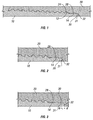
- FIG. 5 shows an alternative embodiment of the present invention showing an alternative design for pin nose 50 .
- pin nose 50 is configured with a triangle shaped preformed rib 52 that has a vertical, or substantially vertical, wall 54 at the trailing edge of rib 52 (i.e., the edge furthest from pin nose end 51 ).
- Groove 60 is similarly shaped to mate with rib 52 when the threaded connection is made up.
- Groove 60 in box member 20 has a vertical, or substantially vertical, wall 62 at the leading edge of groove 60 (i.e., the edge furthest from box surface 61 ).
- pin nose end 51 is in contact with, or very nearly in contact with, box surface 61 at the back of the box member 20 prior to expansion of the threaded connection.
- the slanted wall of rib 52 is in contact with the slanted wall of groove 60 , and a small axial gap (a) exists between wall 54 of rib 52 and wall 62 of groove 60 .
- rib 52 moves backward (i.e., toward the left in FIG. 6 ) until the wall 54 of rib 52 contacts wall 62 of groove 60 .
- the contact between wall 54 of rib 52 and wall 62 of groove 60 creates a metal-to-metal seal between pin member 10 and box member 20 .
- the axial force acting on the point of contact between walls 54 and 62 generates a high bearing pressure that is equal to or greater than the internal pressure within the expandable tubulars.
- the bearing pressure of the metal-to-metal seal so formed prevents well fluids from migrating past the point of contact between walls 54 and 62 .
- the expansion process creates a high-pressure seal.
- the contact between walls 54 and 62 resists or impedes further retracting of the pin nose end 51 from the box surface 61 , thereby limiting the size of axial gap (a) created during the expansion process.
- a resilient seal 70 can be placed in a groove in the threaded portion of box member 20 between the metal-to-metal seal formed by the contact of walls 54 and 62 and the interengaged threads of the pin member 10 and box member 20 (as shown in FIGS. 5 and 6 ).
- the resilient seal 70 can be placed in a groove in the threaded portion of pin member 10 .
- FIG. 7 shows an alternative embodiment of the present invention showing an alternative design for pin nose 80 .
- pin nose 80 is configured with a rib 82 that is designed with a slanted top wall 85 , a vertical (or substantially vertical) front wall 83 , and an angled rear wall 84 .
- Groove 90 in box member 20 is similarly shaped to mate with rib 82 when the threaded connection is made up.
- Groove 90 has an angled rear wall 92 at the leading edge of groove 90 (the wall furthest from box surface 91 ).
- pin nose end 81 is in contact with, or very nearly in contact with, box surface 91 at the back of the box member 20 prior to expansion of the threaded connection.
- the slanted top wall 85 of rib 82 is in contact with the slanted wall of groove 90 , and a small axial gap (a) exists between angled rear wall 84 of rib 82 and angled rear wall 92 of groove 90 .
- rib 82 moves backward (i.e., toward the left in FIG. 8 ) until the angled rear wall 84 of rib 82 contacts angled rear wall 92 of groove 90 .
- the contact between angled rear wall 84 of rib 82 and angled rear wall 92 of groove 90 creates a metal-to-metal seal between pin member 10 and box member 20 .
- the axial force acting on the point of contact between angled rear wall 84 and angled rear wall 92 generates a high bearing pressure that is equal to or greater than the internal pressure within the expandable tubulars.
- the sealing ability of the expandable connection is enhanced by the “slanting” of angled rear walls 84 and 92 .
- a reverse trapping angle is incorporated into the sliding seal of the present invention.
- angled rear wall 84 and angled rear wall 92 have been machined with substantially equal trapping angles.
- the trapping angle is preferably in the range of 15-25 degrees. The above range of degrees for the reverse trapping angle of angled rear wall 84 and angled rear wall 92 is given by way of example only.
- the reverse trapping angle incorporated into the sliding seal of the present invention is designed to force pin nose 80 outwardly as angled rear wall 84 is forced into contact with angled rear wall 92 .
- pin nose 80 is forced in an outwardly direction, the bearing pressure between slanted top wall 85 of rib 82 and the corresponding slanted wall of groove 90 is increased.
- a larger trapping angle will cause higher bearing pressure between those surfaces.
- Both the increased bearing pressure between those surfaces and the increased bearing pressure caused by the forces acting on the surfaces at the trapping angles will produce a high strength metal-to-metal seal between pin member 10 and box member 20 .
- the bearing pressure of the metal-to-metal seal so formed prevents fluids from migrating past the point of contact between angled rear wall 84 and angled rear wall 92 . As such, the expansion process creates a high-pressure seal.
- angled rear wall 84 and angled rear wall 92 resists or impedes further retracting of the pin nose end 81 from the box surface 91 , thereby limiting the size of axial gap (a) created during the expansion process. Further, such contact helps keep the threads of the pin member 10 engaged with the threads of the box member 20 .
- a resilient seal 70 can be placed in a groove in the box member 20 between the metal-to-metal seal formed by the contact of angled rear wall 84 and angled rear wall 92 and the interengaged threads of the pin member 10 and box member 20 (as shown in FIGS. 7 and 8 ).
- the sliding seal of the present invention can be formed when the tubulars are expanded by any known tubular expansion method, including rotary expansion techniques. For example, if the tubulars are expanded by moving an expansion cone through the tubulars, the sliding seal will be created as discussed above. If the tubulars are expanded by a rotary expansion tool, the pin tends to increase in length, thereby causing the pin nose to move into engagement with (or toward) the back of the box member during the expansion process. In such a situation, the pin and box members prior to expansion would look similar to FIG. 3 . As the connection is expanded, the rib on the pin nose will move forward until a portion of the rib contacts a portion of the groove in the box member (similar to what is shown in FIG. 2 ).
- the sliding seal of the present invention can be utilized on tubulars that are not connected by traditional threaded means.
- the sliding seal of the present invention can be utilized on tubulars to be expanded that are made-up through other connection means such as the method of joining expandable tubulars disclosed in United States Published Patent Application 2004/0069498 A1 published on Apr. 15, 2004, which is incorporated herein by reference.
- the rib and groove or multiple rib and groove combinations will be located on concentric sections of the tubulars such that the expansion process creates the seal as explained above.
Landscapes
- Engineering & Computer Science (AREA)
- Mining & Mineral Resources (AREA)
- Geology (AREA)
- Life Sciences & Earth Sciences (AREA)
- General Engineering & Computer Science (AREA)
- Fluid Mechanics (AREA)
- Environmental & Geological Engineering (AREA)
- Physics & Mathematics (AREA)
- Mechanical Engineering (AREA)
- General Life Sciences & Earth Sciences (AREA)
- Geochemistry & Mineralogy (AREA)
- Non-Disconnectible Joints And Screw-Threaded Joints (AREA)
- Earth Drilling (AREA)
- Gasket Seals (AREA)
Abstract
Description
Claims (33)
Priority Applications (11)
Application Number | Priority Date | Filing Date | Title |
---|---|---|---|
US11/201,499 US7798536B2 (en) | 2005-08-11 | 2005-08-11 | Reverse sliding seal for expandable tubular connections |
GB0816235A GB2449805B (en) | 2005-08-11 | 2006-08-07 | Reverse sliding seal for expandable tubular connections |
GB0816234A GB2449804B (en) | 2005-08-11 | 2006-08-07 | Reverse sliding seal for expandable tubular connections |
GB0615602A GB2429220B (en) | 2005-08-11 | 2006-08-07 | Reverse sliding seal for expandable tubular connections |
CA2865078A CA2865078C (en) | 2005-08-11 | 2006-08-09 | An expandable threaded tubular connection |
CA2881130A CA2881130C (en) | 2005-08-11 | 2006-08-09 | An expandable threaded tubular connection |
CA2881125A CA2881125C (en) | 2005-08-11 | 2006-08-09 | Reverse sliding seal for expandable tubular connections |
CA2555709A CA2555709C (en) | 2005-08-11 | 2006-08-09 | Reverse sliding seal for expandable tubular connections |
CA2881342A CA2881342C (en) | 2005-08-11 | 2006-08-09 | An expandable threaded tubular connection |
CA2757151A CA2757151C (en) | 2005-08-11 | 2006-08-09 | Reverse sliding seal for expandable tubular connections |
US12/855,422 US20100320754A1 (en) | 2005-08-11 | 2010-08-12 | Reverse sliding seal for expandable tubular connections |
Applications Claiming Priority (1)
Application Number | Priority Date | Filing Date | Title |
---|---|---|---|
US11/201,499 US7798536B2 (en) | 2005-08-11 | 2005-08-11 | Reverse sliding seal for expandable tubular connections |
Related Child Applications (1)
Application Number | Title | Priority Date | Filing Date |
---|---|---|---|
US12/855,422 Division US20100320754A1 (en) | 2005-08-11 | 2010-08-12 | Reverse sliding seal for expandable tubular connections |
Publications (2)
Publication Number | Publication Date |
---|---|
US20070035130A1 US20070035130A1 (en) | 2007-02-15 |
US7798536B2 true US7798536B2 (en) | 2010-09-21 |
Family
ID=37027315
Family Applications (2)
Application Number | Title | Priority Date | Filing Date |
---|---|---|---|
US11/201,499 Expired - Fee Related US7798536B2 (en) | 2005-08-11 | 2005-08-11 | Reverse sliding seal for expandable tubular connections |
US12/855,422 Abandoned US20100320754A1 (en) | 2005-08-11 | 2010-08-12 | Reverse sliding seal for expandable tubular connections |
Family Applications After (1)
Application Number | Title | Priority Date | Filing Date |
---|---|---|---|
US12/855,422 Abandoned US20100320754A1 (en) | 2005-08-11 | 2010-08-12 | Reverse sliding seal for expandable tubular connections |
Country Status (3)
Country | Link |
---|---|
US (2) | US7798536B2 (en) |
CA (6) | CA2555709C (en) |
GB (3) | GB2449805B (en) |
Cited By (8)
Publication number | Priority date | Publication date | Assignee | Title |
---|---|---|---|---|
US20090302604A1 (en) * | 2005-10-11 | 2009-12-10 | Enventure Global Technology, L.L.C. | Method and Apparatus for coupling Expandable Tubular Members |
US20100225107A1 (en) * | 2006-02-17 | 2010-09-09 | Norsk Hydro Asa | Gas Tight Tubular Joint or Connection |
US20100320754A1 (en) * | 2005-08-11 | 2010-12-23 | Hashem Ghazi J | Reverse sliding seal for expandable tubular connections |
US8894101B2 (en) * | 2012-09-07 | 2014-11-25 | Vetco Gray Inc. | Protected integral metal to metal seal |
US9453393B2 (en) | 2014-01-22 | 2016-09-27 | Seminole Services, LLC | Apparatus and method for setting a liner |
US9926749B2 (en) | 2014-04-04 | 2018-03-27 | Enventure Global Technology Inc. | Expandable metal-to-metal seal connection |
US10167679B2 (en) * | 2014-03-14 | 2019-01-01 | Rubberatkins Limited | Coupling, downhole device, assembly and method |
US10428594B2 (en) | 2013-11-22 | 2019-10-01 | Vetco Gray, LLC | Alignment guide feature for metal to metal seal protection on mechanical connections and couplings |
Families Citing this family (17)
Publication number | Priority date | Publication date | Assignee | Title |
---|---|---|---|---|
US20070228729A1 (en) * | 2003-03-06 | 2007-10-04 | Grimmett Harold M | Tubular goods with threaded integral joint connections |
US20060006648A1 (en) * | 2003-03-06 | 2006-01-12 | Grimmett Harold M | Tubular goods with threaded integral joint connections |
US7549682B2 (en) * | 2005-09-19 | 2009-06-23 | Vetco Gray Inc. | Threaded pipe connector |
FR2913746B1 (en) * | 2007-03-14 | 2011-06-24 | Vallourec Mannesmann Oil & Gas | SEALED TUBULAR THREAD SEAL FOR INTERNAL AND EXTERNAL PRESSURE SOLUTIONS |
US20100052319A1 (en) * | 2008-08-28 | 2010-03-04 | Mohawk Energy Ltd. | Dual Seal Expandable Tubular Connection |
FR2939490B1 (en) * | 2008-12-10 | 2013-01-18 | Vallourec Mannesmann Oil & Gas | SEALED TUBULAR JOINT USED IN THE OIL INDUSTRY AND METHOD OF MAKING SAME |
FR2940677B1 (en) | 2008-12-29 | 2016-07-22 | Vallourec Mannesmann Oil & Gas France | SEALED TUBULAR JOINT USED IN THE PETROLEUM INDUSTRY |
CN101864906A (en) * | 2010-07-09 | 2010-10-20 | 天津钢管集团股份有限公司 | Bending-resistant oil casing threaded connection structure |
US9057226B2 (en) * | 2012-05-03 | 2015-06-16 | Vetco Gray Inc. | Method of forming a machinable surface |
WO2014151886A2 (en) * | 2013-03-15 | 2014-09-25 | Weatherford/Lamb, Inc. | Couplings for expandable tubular |
CN103362457B (en) * | 2013-08-03 | 2015-07-22 | 无锡西姆莱斯石油专用管制造有限公司 | Cambered surface and plane sealed variable tooth wide wedge-type coupling structure and oil well pipe structure |
KR101536472B1 (en) * | 2013-12-25 | 2015-07-14 | 주식회사 포스코 | Connecting Device for Metal Pipe |
US10480693B2 (en) * | 2014-06-20 | 2019-11-19 | Nippon Steel Corporation | Threaded joint for steel pipes |
CN106194045B (en) * | 2016-09-21 | 2019-01-18 | 库尔勒施得石油技术服务有限公司 | Drilling rod |
CN110273655A (en) * | 2019-07-26 | 2019-09-24 | 西南石油大学 | A kind of novel direct-connected retaining ring pipe screw thread structure |
CN110899445B (en) * | 2019-12-17 | 2021-08-13 | 浙江普兴电子科技有限公司 | Mold and method for preparing sine type deployable sealing structure by spinning process |
WO2023048697A1 (en) * | 2021-09-21 | 2023-03-30 | Halliburton Energy Services, Inc. | Expandable metal for junction locking and junction sealant applications |
Citations (86)
Publication number | Priority date | Publication date | Assignee | Title |
---|---|---|---|---|
US1460769A (en) | 1921-07-07 | 1923-07-03 | Nat Tube Co | Pipe |
US2005631A (en) | 1934-09-05 | 1935-06-18 | O O Latimer | Pipe coupling |
US2065595A (en) | 1934-08-09 | 1936-12-29 | Jones & Laughlin Steel Corp | Tubular product and manufacture thereof |
US2494128A (en) | 1945-11-14 | 1950-01-10 | Nat Supply Co | Method of increasing the axial tensile strength of threaded joints |
US2980451A (en) | 1957-04-17 | 1961-04-18 | Atlas Pipe Inc | Threaded pipe joint having an extrudable generally non-resilient sealing means |
US3047316A (en) | 1958-10-01 | 1962-07-31 | Atlas Bradford Company | Packed pin and box drill pipe coupling with means preventing extrusion of packing ring |
US3067593A (en) | 1960-08-29 | 1962-12-11 | American Iron & Machine Works | Integral tool joint drill pipe |
US3080179A (en) | 1959-10-06 | 1963-03-05 | Huntsinger Associates | Slip engaging portion of drill string formed of increased wall thickness and reduced hardness |
US3475038A (en) | 1968-01-08 | 1969-10-28 | Lee Matherne | Pipe stabber with setscrews |
US3489437A (en) | 1965-11-05 | 1970-01-13 | Vallourec | Joint connection for pipes |
US3508771A (en) | 1964-09-04 | 1970-04-28 | Vallourec | Joints,particularly for interconnecting pipe sections employed in oil well operations |
US3870351A (en) | 1972-03-31 | 1975-03-11 | Sumitomo Metal Ind | Threaded tube joint structure for casing, particularly oil well tubing |
US3989284A (en) | 1975-04-23 | 1976-11-02 | Hydril Company | Tubular connection |
US4253687A (en) | 1979-06-11 | 1981-03-03 | Whiting Oilfield Rental, Inc. | Pipe connection |
US4317585A (en) | 1980-05-30 | 1982-03-02 | Reynolds Metals Company | Torqued drill pipe identification |
USRE31123E (en) | 1977-01-03 | 1983-01-11 | Centron Corporation | Pipe section and coupling |
EP0127560A2 (en) | 1983-04-29 | 1984-12-05 | Baker Hughes Incorporated | Threaded coupling comprising a ventable seal |
US4601491A (en) | 1983-10-19 | 1986-07-22 | Vetco Offshore, Inc. | Pipe connector |
US4611838A (en) * | 1982-02-27 | 1986-09-16 | Mannesmann Aktiengesellschaft | Fluidtight pipe joint |
US4619472A (en) * | 1985-05-02 | 1986-10-28 | Nippon Steel Corporation | Pipe coupling |
US4629221A (en) * | 1983-04-05 | 1986-12-16 | Hunting Oilfield Services (Uk) Ltd. | Pipe connectors |
US4629225A (en) | 1985-08-09 | 1986-12-16 | Inco Alloys International, Inc. | Pipe joint for corrosion resistant alloys |
US4648627A (en) | 1984-01-18 | 1987-03-10 | Dril-Quip, Inc. | Stabbing connector |
US4674773A (en) | 1984-01-23 | 1987-06-23 | Teleco Oilfield Services Inc. | Insulating coupling for drill collars and method of manufacture thereof |
US4676529A (en) | 1986-03-24 | 1987-06-30 | Hydril Company | Pipe joint |
US4676528A (en) | 1984-04-30 | 1987-06-30 | Gray Theodor R | Method and apparatus for restoring tubular upsets |
US4688828A (en) | 1986-04-02 | 1987-08-25 | Shaffer Donald U | Tubing joint for corrosion protection |
US4703959A (en) | 1986-02-10 | 1987-11-03 | Hydril Company | Threaded pipe connection with compressible seal ring |
US4707001A (en) | 1986-06-20 | 1987-11-17 | Seal-Tech, Inc. | Liner connection |
US4822081A (en) | 1987-03-23 | 1989-04-18 | Xl Systems | Driveable threaded tubular connection |
US4846507A (en) | 1981-06-01 | 1989-07-11 | George B. Geary | Casing connector |
US4893658A (en) | 1987-05-27 | 1990-01-16 | Sumitomo Metal Industries, Ltd. | FRP pipe with threaded ends |
US4958862A (en) | 1988-10-03 | 1990-09-25 | Dalmine Spa | Hermetic metal pipe joint |
US5348095A (en) | 1992-06-09 | 1994-09-20 | Shell Oil Company | Method of creating a wellbore in an underground formation |
US5415441A (en) | 1994-02-28 | 1995-05-16 | Halliburton Company | Push-on coupling apparatus for tubular well completion structures |
US5427418A (en) | 1986-07-18 | 1995-06-27 | Watts; John D. | High strength, low torque threaded tubular connection |
US5681059A (en) * | 1995-12-15 | 1997-10-28 | Mackie; Michael J. | Pipe connector |
WO1998042947A1 (en) | 1997-03-21 | 1998-10-01 | Petroline Wellsystems Limited | Expandable slotted tubing string and method for connecting such a tubing string |
US5826921A (en) * | 1991-11-25 | 1998-10-27 | Woolley; Brown J. | Threaded pipe joint |
US5924745A (en) | 1995-05-24 | 1999-07-20 | Petroline Wellsystems Limited | Connector assembly for an expandable slotted pipe |
US5954374A (en) | 1996-04-26 | 1999-09-21 | Oil States Industries (Uk) Ltd. | Pipe connectors |
US5964486A (en) * | 1997-03-24 | 1999-10-12 | Oil States Industries (Uk) Limited | Pipe connectors |
US6042153A (en) | 1998-02-25 | 2000-03-28 | Grant Prideco, Inc. | Threaded connection for internally clad pipe |
US6112818A (en) | 1995-11-09 | 2000-09-05 | Petroline Wellsystems Limited | Downhole setting tool for an expandable tubing |
US6123368A (en) | 1998-03-19 | 2000-09-26 | Hydril Company | Two-step, differential diameter wedge threaded connector |
WO2001004535A1 (en) | 1999-07-09 | 2001-01-18 | Enventure Global Technology | Two-step radial expansion |
WO2001004520A1 (en) | 1999-07-13 | 2001-01-18 | Enventure Global Technology, Llc | Expandable joint connector |
WO2001018353A1 (en) | 1999-09-06 | 2001-03-15 | E2 Tech Limited | Expandable downhole tubing |
EP1106778A1 (en) | 1999-12-09 | 2001-06-13 | Hydril Company | Seal for expandable tubular connections |
GB2361724A (en) | 1999-04-26 | 2001-10-31 | Shell Int Research | Wellbore casing with radially expanded liner extruded off of a mandrel |
US6322110B1 (en) * | 1997-08-11 | 2001-11-27 | Marubeni Tubulars, Inc. | Tubular connection |
US6322109B1 (en) | 1995-12-09 | 2001-11-27 | Weatherford/Lamb, Inc. | Expandable tubing connector for expandable tubing |
US6328113B1 (en) | 1998-11-16 | 2001-12-11 | Shell Oil Company | Isolation of subterranean zones |
EP1179700A2 (en) | 2000-08-10 | 2002-02-13 | Hydril Company | Double flex seal for tubular connection |
US6425444B1 (en) | 1998-12-22 | 2002-07-30 | Weatherford/Lamb, Inc. | Method and apparatus for downhole sealing |
US6454013B1 (en) | 1997-11-01 | 2002-09-24 | Weatherford/Lamb, Inc. | Expandable downhole tubing |
US6457532B1 (en) | 1998-12-22 | 2002-10-01 | Weatherford/Lamb, Inc. | Procedures and equipment for profiling and jointing of pipes |
US20020163192A1 (en) * | 2000-06-30 | 2002-11-07 | Jean-Luc Coulon | Tubular threaded joint capable of being subjected to diametral expansion |
US6510896B2 (en) | 2001-05-04 | 2003-01-28 | Weatherford/Lamb, Inc. | Apparatus and methods for utilizing expandable sand screen in wellbores |
US20030067166A1 (en) | 2001-10-09 | 2003-04-10 | Sivley Robert S. | Radially expandable tubular connection |
US20030075924A1 (en) * | 1996-05-15 | 2003-04-24 | Olivier Huey P. | Connection |
US20030107213A1 (en) * | 2001-12-06 | 2003-06-12 | Baugh John L. | Expandable locking thread joint |
WO2003060370A1 (en) | 2002-01-03 | 2003-07-24 | Vallourec Mannesmann Oil & Gas France | Method for making a sealed tubular joint with plastic expansion |
US6604763B1 (en) | 1998-12-07 | 2003-08-12 | Shell Oil Company | Expandable connector |
US20030234538A1 (en) | 2002-06-24 | 2003-12-25 | Weatherford/Lamb, Inc. | Multi-point high pressure seal for expandable tubular connections |
US6681875B2 (en) | 2000-10-27 | 2004-01-27 | Sandvik Ab | Guide tube of a drill string configured to facilitate unscrewing thereof from a member of the drill string |
US20040017081A1 (en) | 2002-07-06 | 2004-01-29 | Simpson Neil Andrew Abercrombie | Coupling tubulars |
US6695012B1 (en) | 1999-10-12 | 2004-02-24 | Shell Oil Company | Lubricant coating for expandable tubular members |
US6722443B1 (en) | 1998-08-08 | 2004-04-20 | Weatherford/Lamb, Inc. | Connector for expandable well screen |
GB2394236A (en) | 2002-09-13 | 2004-04-21 | Weatherford Lamb | Expandable coupling |
US6745845B2 (en) | 1998-11-16 | 2004-06-08 | Shell Oil Company | Isolation of subterranean zones |
US6752436B1 (en) * | 2000-03-31 | 2004-06-22 | Vallourec Mannesmann Oil & Gas France | Fatigue-resistant threaded bevelled tubular element |
US6767035B2 (en) | 2002-03-11 | 2004-07-27 | Weatherford/Lamb, Inc. | High torque modified profile threaded tubular connection |
US20040174017A1 (en) | 2003-03-06 | 2004-09-09 | Lone Star Steel Company | Tubular goods with expandable threaded connections |
US20040262919A1 (en) * | 2001-12-07 | 2004-12-30 | Pierre Dutilleul | Premium tubular threaded joint comprising at least a threaded element with end lip |
US20050087983A1 (en) * | 2002-06-28 | 2005-04-28 | Vallourec Mannesmann Oil & Gas France | Reinforced tubular joint for improved sealing-tightness after plastic expansion |
FR2863029A1 (en) | 2003-11-28 | 2005-06-03 | Vallourec Mannesmann Oil & Gas | Tubular joint, e.g. for hydrocarbon pipe, has lip extending male thread and curved seating on female threaded part, so that after plastic deformation by radial expansion, joint becomes sealed |
US6905150B2 (en) * | 2002-05-16 | 2005-06-14 | Tenaris Connections Ag | Threaded pipe joint |
WO2005064218A1 (en) | 2003-11-28 | 2005-07-14 | Vallourec Mannesmann Oil & Gas France | Method of assembling two hermetic threaded tubular joints comprising a local and initial thinned thickness, by means of plastic expansion |
WO2005064217A1 (en) | 2003-11-28 | 2005-07-14 | Vallourec Mannesmann Oil & Gas France | Production by plastic expansion of a sealed tubular joint with inclined abutting surface(s) |
US20050212290A1 (en) * | 2002-01-03 | 2005-09-29 | Vallourec Mannesmann Oil & Gas France | Threaded tubular joint comprising sealing surfaces |
US20050236834A1 (en) * | 2004-04-21 | 2005-10-27 | Baker Hughes Incorporated | Expandable tubular connection |
US20070035131A1 (en) | 2005-08-11 | 2007-02-15 | Grinaldi Ltd | Expandable tubular connection |
US20070035132A1 (en) | 2005-08-11 | 2007-02-15 | Grinaldi Ltd | Expandable tubular connection |
US20070035127A1 (en) | 2005-08-12 | 2007-02-15 | Benzie Scott A | Protective sleeve for tubular connection |
US20070187951A1 (en) * | 2004-03-26 | 2007-08-16 | Vallourec Mannesmann Oil & Gas France | Threaded tubular connection which is resistant to bending stresses |
Family Cites Families (4)
Publication number | Priority date | Publication date | Assignee | Title |
---|---|---|---|---|
US6997264B2 (en) * | 2002-10-10 | 2006-02-14 | Weatherford/Lamb, Inc. | Method of jointing and running expandable tubulars |
FR2852076B1 (en) * | 2003-03-07 | 2005-06-10 | Vallourec Mannesmann Oil & Gas | METHOD FOR MAKING A RADIALLY EXPANSION-SEALED TUBULAR THREAD SEAL |
EP1646074A4 (en) * | 2003-07-09 | 2007-10-03 | Nikon Corp | Exposure apparatus and method for manufacturing device |
US7798536B2 (en) * | 2005-08-11 | 2010-09-21 | Weatherford/Lamb, Inc. | Reverse sliding seal for expandable tubular connections |
-
2005
- 2005-08-11 US US11/201,499 patent/US7798536B2/en not_active Expired - Fee Related
-
2006
- 2006-08-07 GB GB0816235A patent/GB2449805B/en not_active Expired - Fee Related
- 2006-08-07 GB GB0615602A patent/GB2429220B/en not_active Expired - Fee Related
- 2006-08-07 GB GB0816234A patent/GB2449804B/en not_active Expired - Fee Related
- 2006-08-09 CA CA2555709A patent/CA2555709C/en not_active Expired - Fee Related
- 2006-08-09 CA CA2881130A patent/CA2881130C/en not_active Expired - Fee Related
- 2006-08-09 CA CA2881342A patent/CA2881342C/en not_active Expired - Fee Related
- 2006-08-09 CA CA2881125A patent/CA2881125C/en not_active Expired - Fee Related
- 2006-08-09 CA CA2865078A patent/CA2865078C/en not_active Expired - Fee Related
- 2006-08-09 CA CA2757151A patent/CA2757151C/en not_active Expired - Fee Related
-
2010
- 2010-08-12 US US12/855,422 patent/US20100320754A1/en not_active Abandoned
Patent Citations (100)
Publication number | Priority date | Publication date | Assignee | Title |
---|---|---|---|---|
US1460769A (en) | 1921-07-07 | 1923-07-03 | Nat Tube Co | Pipe |
US2065595A (en) | 1934-08-09 | 1936-12-29 | Jones & Laughlin Steel Corp | Tubular product and manufacture thereof |
US2005631A (en) | 1934-09-05 | 1935-06-18 | O O Latimer | Pipe coupling |
US2494128A (en) | 1945-11-14 | 1950-01-10 | Nat Supply Co | Method of increasing the axial tensile strength of threaded joints |
US2980451A (en) | 1957-04-17 | 1961-04-18 | Atlas Pipe Inc | Threaded pipe joint having an extrudable generally non-resilient sealing means |
US3047316A (en) | 1958-10-01 | 1962-07-31 | Atlas Bradford Company | Packed pin and box drill pipe coupling with means preventing extrusion of packing ring |
US3080179A (en) | 1959-10-06 | 1963-03-05 | Huntsinger Associates | Slip engaging portion of drill string formed of increased wall thickness and reduced hardness |
US3067593A (en) | 1960-08-29 | 1962-12-11 | American Iron & Machine Works | Integral tool joint drill pipe |
US3508771A (en) | 1964-09-04 | 1970-04-28 | Vallourec | Joints,particularly for interconnecting pipe sections employed in oil well operations |
US3489437A (en) | 1965-11-05 | 1970-01-13 | Vallourec | Joint connection for pipes |
US3475038A (en) | 1968-01-08 | 1969-10-28 | Lee Matherne | Pipe stabber with setscrews |
US3870351A (en) | 1972-03-31 | 1975-03-11 | Sumitomo Metal Ind | Threaded tube joint structure for casing, particularly oil well tubing |
US3989284A (en) | 1975-04-23 | 1976-11-02 | Hydril Company | Tubular connection |
USRE31123E (en) | 1977-01-03 | 1983-01-11 | Centron Corporation | Pipe section and coupling |
US4253687A (en) | 1979-06-11 | 1981-03-03 | Whiting Oilfield Rental, Inc. | Pipe connection |
US4317585A (en) | 1980-05-30 | 1982-03-02 | Reynolds Metals Company | Torqued drill pipe identification |
US4846507A (en) | 1981-06-01 | 1989-07-11 | George B. Geary | Casing connector |
US4611838A (en) * | 1982-02-27 | 1986-09-16 | Mannesmann Aktiengesellschaft | Fluidtight pipe joint |
US4629221A (en) * | 1983-04-05 | 1986-12-16 | Hunting Oilfield Services (Uk) Ltd. | Pipe connectors |
EP0127560A2 (en) | 1983-04-29 | 1984-12-05 | Baker Hughes Incorporated | Threaded coupling comprising a ventable seal |
US4601491A (en) | 1983-10-19 | 1986-07-22 | Vetco Offshore, Inc. | Pipe connector |
US4648627A (en) | 1984-01-18 | 1987-03-10 | Dril-Quip, Inc. | Stabbing connector |
US4674773A (en) | 1984-01-23 | 1987-06-23 | Teleco Oilfield Services Inc. | Insulating coupling for drill collars and method of manufacture thereof |
US4676528A (en) | 1984-04-30 | 1987-06-30 | Gray Theodor R | Method and apparatus for restoring tubular upsets |
US4619472A (en) * | 1985-05-02 | 1986-10-28 | Nippon Steel Corporation | Pipe coupling |
US4629225A (en) | 1985-08-09 | 1986-12-16 | Inco Alloys International, Inc. | Pipe joint for corrosion resistant alloys |
US4703959A (en) | 1986-02-10 | 1987-11-03 | Hydril Company | Threaded pipe connection with compressible seal ring |
US4676529A (en) | 1986-03-24 | 1987-06-30 | Hydril Company | Pipe joint |
US4688828A (en) | 1986-04-02 | 1987-08-25 | Shaffer Donald U | Tubing joint for corrosion protection |
US4707001A (en) | 1986-06-20 | 1987-11-17 | Seal-Tech, Inc. | Liner connection |
US5427418A (en) | 1986-07-18 | 1995-06-27 | Watts; John D. | High strength, low torque threaded tubular connection |
US4822081A (en) | 1987-03-23 | 1989-04-18 | Xl Systems | Driveable threaded tubular connection |
US4893658A (en) | 1987-05-27 | 1990-01-16 | Sumitomo Metal Industries, Ltd. | FRP pipe with threaded ends |
US4958862A (en) | 1988-10-03 | 1990-09-25 | Dalmine Spa | Hermetic metal pipe joint |
US5826921A (en) * | 1991-11-25 | 1998-10-27 | Woolley; Brown J. | Threaded pipe joint |
US5348095A (en) | 1992-06-09 | 1994-09-20 | Shell Oil Company | Method of creating a wellbore in an underground formation |
US5415441A (en) | 1994-02-28 | 1995-05-16 | Halliburton Company | Push-on coupling apparatus for tubular well completion structures |
US5984568A (en) | 1995-05-24 | 1999-11-16 | Shell Oil Company | Connector assembly for an expandable slotted pipe |
US5924745A (en) | 1995-05-24 | 1999-07-20 | Petroline Wellsystems Limited | Connector assembly for an expandable slotted pipe |
US6112818A (en) | 1995-11-09 | 2000-09-05 | Petroline Wellsystems Limited | Downhole setting tool for an expandable tubing |
US6322109B1 (en) | 1995-12-09 | 2001-11-27 | Weatherford/Lamb, Inc. | Expandable tubing connector for expandable tubing |
US5681059A (en) * | 1995-12-15 | 1997-10-28 | Mackie; Michael J. | Pipe connector |
US5954374A (en) | 1996-04-26 | 1999-09-21 | Oil States Industries (Uk) Ltd. | Pipe connectors |
US20030075924A1 (en) * | 1996-05-15 | 2003-04-24 | Olivier Huey P. | Connection |
WO1998042947A1 (en) | 1997-03-21 | 1998-10-01 | Petroline Wellsystems Limited | Expandable slotted tubing string and method for connecting such a tubing string |
US5964486A (en) * | 1997-03-24 | 1999-10-12 | Oil States Industries (Uk) Limited | Pipe connectors |
US6322110B1 (en) * | 1997-08-11 | 2001-11-27 | Marubeni Tubulars, Inc. | Tubular connection |
US6454013B1 (en) | 1997-11-01 | 2002-09-24 | Weatherford/Lamb, Inc. | Expandable downhole tubing |
US6042153A (en) | 1998-02-25 | 2000-03-28 | Grant Prideco, Inc. | Threaded connection for internally clad pipe |
US6273474B1 (en) | 1998-02-25 | 2001-08-14 | Grant Prideco, L.P. | Threaded connection for internally clad pipe |
US6123368A (en) | 1998-03-19 | 2000-09-26 | Hydril Company | Two-step, differential diameter wedge threaded connector |
US6722443B1 (en) | 1998-08-08 | 2004-04-20 | Weatherford/Lamb, Inc. | Connector for expandable well screen |
US6328113B1 (en) | 1998-11-16 | 2001-12-11 | Shell Oil Company | Isolation of subterranean zones |
US6745845B2 (en) | 1998-11-16 | 2004-06-08 | Shell Oil Company | Isolation of subterranean zones |
US6604763B1 (en) | 1998-12-07 | 2003-08-12 | Shell Oil Company | Expandable connector |
US6457532B1 (en) | 1998-12-22 | 2002-10-01 | Weatherford/Lamb, Inc. | Procedures and equipment for profiling and jointing of pipes |
US6425444B1 (en) | 1998-12-22 | 2002-07-30 | Weatherford/Lamb, Inc. | Method and apparatus for downhole sealing |
GB2361724A (en) | 1999-04-26 | 2001-10-31 | Shell Int Research | Wellbore casing with radially expanded liner extruded off of a mandrel |
WO2001004535A1 (en) | 1999-07-09 | 2001-01-18 | Enventure Global Technology | Two-step radial expansion |
WO2001004520A1 (en) | 1999-07-13 | 2001-01-18 | Enventure Global Technology, Llc | Expandable joint connector |
US6409175B1 (en) | 1999-07-13 | 2002-06-25 | Grant Prideco, Inc. | Expandable joint connector |
WO2001018353A1 (en) | 1999-09-06 | 2001-03-15 | E2 Tech Limited | Expandable downhole tubing |
US6695012B1 (en) | 1999-10-12 | 2004-02-24 | Shell Oil Company | Lubricant coating for expandable tubular members |
EP1106778A1 (en) | 1999-12-09 | 2001-06-13 | Hydril Company | Seal for expandable tubular connections |
US6752436B1 (en) * | 2000-03-31 | 2004-06-22 | Vallourec Mannesmann Oil & Gas France | Fatigue-resistant threaded bevelled tubular element |
US20020163192A1 (en) * | 2000-06-30 | 2002-11-07 | Jean-Luc Coulon | Tubular threaded joint capable of being subjected to diametral expansion |
US6712401B2 (en) | 2000-06-30 | 2004-03-30 | Vallourec Mannesmann Oil & Gas France | Tubular threaded joint capable of being subjected to diametral expansion |
EP1179700A2 (en) | 2000-08-10 | 2002-02-13 | Hydril Company | Double flex seal for tubular connection |
US6626471B2 (en) | 2000-08-10 | 2003-09-30 | Hydril Company | Double flex seal for tubular connection |
US6681875B2 (en) | 2000-10-27 | 2004-01-27 | Sandvik Ab | Guide tube of a drill string configured to facilitate unscrewing thereof from a member of the drill string |
US6510896B2 (en) | 2001-05-04 | 2003-01-28 | Weatherford/Lamb, Inc. | Apparatus and methods for utilizing expandable sand screen in wellbores |
US6607220B2 (en) | 2001-10-09 | 2003-08-19 | Hydril Company | Radially expandable tubular connection |
US20030067166A1 (en) | 2001-10-09 | 2003-04-10 | Sivley Robert S. | Radially expandable tubular connection |
US6619696B2 (en) | 2001-12-06 | 2003-09-16 | Baker Hughes Incorporated | Expandable locking thread joint |
US20030107213A1 (en) * | 2001-12-06 | 2003-06-12 | Baugh John L. | Expandable locking thread joint |
US20040262919A1 (en) * | 2001-12-07 | 2004-12-30 | Pierre Dutilleul | Premium tubular threaded joint comprising at least a threaded element with end lip |
WO2003060370A1 (en) | 2002-01-03 | 2003-07-24 | Vallourec Mannesmann Oil & Gas France | Method for making a sealed tubular joint with plastic expansion |
US20050212290A1 (en) * | 2002-01-03 | 2005-09-29 | Vallourec Mannesmann Oil & Gas France | Threaded tubular joint comprising sealing surfaces |
US6767035B2 (en) | 2002-03-11 | 2004-07-27 | Weatherford/Lamb, Inc. | High torque modified profile threaded tubular connection |
US6905150B2 (en) * | 2002-05-16 | 2005-06-14 | Tenaris Connections Ag | Threaded pipe joint |
US20030234538A1 (en) | 2002-06-24 | 2003-12-25 | Weatherford/Lamb, Inc. | Multi-point high pressure seal for expandable tubular connections |
US6971685B2 (en) * | 2002-06-24 | 2005-12-06 | Weatherford/Lamb, Inc. | Multi-point high pressure seal for expandable tubular connections |
US20050087983A1 (en) * | 2002-06-28 | 2005-04-28 | Vallourec Mannesmann Oil & Gas France | Reinforced tubular joint for improved sealing-tightness after plastic expansion |
US20080007060A1 (en) * | 2002-07-06 | 2008-01-10 | Simpson Neil Andrew Abercrombi | Coupling tubulars |
US20040017081A1 (en) | 2002-07-06 | 2004-01-29 | Simpson Neil Andrew Abercrombie | Coupling tubulars |
US7107663B2 (en) | 2002-09-13 | 2006-09-19 | Weatherford/Lamb, Inc. | Expandable coupling |
GB2394236A (en) | 2002-09-13 | 2004-04-21 | Weatherford Lamb | Expandable coupling |
US20040104575A1 (en) | 2002-09-13 | 2004-06-03 | Peter Ellington | Expandable coupling |
US20040174017A1 (en) | 2003-03-06 | 2004-09-09 | Lone Star Steel Company | Tubular goods with expandable threaded connections |
FR2863029A1 (en) | 2003-11-28 | 2005-06-03 | Vallourec Mannesmann Oil & Gas | Tubular joint, e.g. for hydrocarbon pipe, has lip extending male thread and curved seating on female threaded part, so that after plastic deformation by radial expansion, joint becomes sealed |
WO2005064218A1 (en) | 2003-11-28 | 2005-07-14 | Vallourec Mannesmann Oil & Gas France | Method of assembling two hermetic threaded tubular joints comprising a local and initial thinned thickness, by means of plastic expansion |
WO2005064219A1 (en) | 2003-11-28 | 2005-07-14 | Vallourec Mannesmann Oil & Gas France | Method of producing a hermetic tubular joint comprising local and initial added thickness(es), by means of plastic expansion |
US20070102927A1 (en) * | 2003-11-28 | 2007-05-10 | Vallourec Mannesmann Oil & Gas France | Production by plastic expansion of a sealed tubular joint with inclined abutting surface(s) |
WO2005064217A1 (en) | 2003-11-28 | 2005-07-14 | Vallourec Mannesmann Oil & Gas France | Production by plastic expansion of a sealed tubular joint with inclined abutting surface(s) |
US20070187951A1 (en) * | 2004-03-26 | 2007-08-16 | Vallourec Mannesmann Oil & Gas France | Threaded tubular connection which is resistant to bending stresses |
US20050236834A1 (en) * | 2004-04-21 | 2005-10-27 | Baker Hughes Incorporated | Expandable tubular connection |
GB2430457A (en) | 2004-04-21 | 2007-03-28 | Baker Hughes Inc | Expandable tubular connection |
US20070035131A1 (en) | 2005-08-11 | 2007-02-15 | Grinaldi Ltd | Expandable tubular connection |
US20070035132A1 (en) | 2005-08-11 | 2007-02-15 | Grinaldi Ltd | Expandable tubular connection |
US20070035127A1 (en) | 2005-08-12 | 2007-02-15 | Benzie Scott A | Protective sleeve for tubular connection |
Non-Patent Citations (6)
Title |
---|
General Administrative and Export Office. Atlas Bradford Company. p. 1. (1970-1971). |
Hydril Series 500. "The Wedge Thread". Hydril Tubular Products Division. pp. 1-5. (1985). |
Robert E. Snyder. "How Shell Completes Deep Smackover Sour Gas Wells". pp. 85-88. (Oct. 1971). |
Rucker/Atlas Bradford; Tubing String Design Manual 9 pages (revised Jul. 1972). |
Scott et al. "VAM-PRO A Premium That Cuts Rig Operational Costs," World Oil, pp. 103-146 (Oct. 1995). |
Scott, et al. "2002 Tubing Reference Tables," World Oil, pp. T-3-T-10 (Jan. 2002). |
Cited By (10)
Publication number | Priority date | Publication date | Assignee | Title |
---|---|---|---|---|
US20100320754A1 (en) * | 2005-08-11 | 2010-12-23 | Hashem Ghazi J | Reverse sliding seal for expandable tubular connections |
US20090302604A1 (en) * | 2005-10-11 | 2009-12-10 | Enventure Global Technology, L.L.C. | Method and Apparatus for coupling Expandable Tubular Members |
US20100225107A1 (en) * | 2006-02-17 | 2010-09-09 | Norsk Hydro Asa | Gas Tight Tubular Joint or Connection |
US8894101B2 (en) * | 2012-09-07 | 2014-11-25 | Vetco Gray Inc. | Protected integral metal to metal seal |
GB2522136B (en) * | 2012-09-07 | 2019-12-25 | Vetco Gray Inc | Protected integral metal to metal seal |
US10428594B2 (en) | 2013-11-22 | 2019-10-01 | Vetco Gray, LLC | Alignment guide feature for metal to metal seal protection on mechanical connections and couplings |
US9453393B2 (en) | 2014-01-22 | 2016-09-27 | Seminole Services, LLC | Apparatus and method for setting a liner |
US9976396B2 (en) | 2014-01-22 | 2018-05-22 | Seminole Services, LLC | Apparatus and method for setting a liner |
US10167679B2 (en) * | 2014-03-14 | 2019-01-01 | Rubberatkins Limited | Coupling, downhole device, assembly and method |
US9926749B2 (en) | 2014-04-04 | 2018-03-27 | Enventure Global Technology Inc. | Expandable metal-to-metal seal connection |
Also Published As
Publication number | Publication date |
---|---|
CA2881130A1 (en) | 2007-02-11 |
CA2881125A1 (en) | 2007-02-11 |
CA2555709C (en) | 2012-10-02 |
GB2429220B (en) | 2010-01-13 |
US20100320754A1 (en) | 2010-12-23 |
CA2757151A1 (en) | 2007-02-11 |
GB0615602D0 (en) | 2006-09-13 |
CA2757151C (en) | 2015-06-30 |
CA2881130C (en) | 2016-08-30 |
GB0816234D0 (en) | 2008-10-15 |
GB2449804B (en) | 2009-05-06 |
CA2555709A1 (en) | 2007-02-11 |
GB2429220A (en) | 2007-02-21 |
GB2449805B (en) | 2009-05-06 |
CA2865078C (en) | 2016-03-01 |
GB2449805A (en) | 2008-12-03 |
US20070035130A1 (en) | 2007-02-15 |
GB2449804A (en) | 2008-12-03 |
CA2881342A1 (en) | 2007-02-11 |
GB0816235D0 (en) | 2008-10-15 |
CA2881342C (en) | 2016-08-02 |
CA2881125C (en) | 2015-11-24 |
CA2865078A1 (en) | 2007-02-11 |
Similar Documents
Publication | Publication Date | Title |
---|---|---|
US7798536B2 (en) | Reverse sliding seal for expandable tubular connections | |
US6971685B2 (en) | Multi-point high pressure seal for expandable tubular connections | |
US7452007B2 (en) | Hybrid threaded connection for expandable tubulars | |
US6409175B1 (en) | Expandable joint connector | |
US7887103B2 (en) | Energizing seal for expandable connections | |
US6896049B2 (en) | Deformable member | |
US20070035131A1 (en) | Expandable tubular connection | |
US20070257486A1 (en) | Elastomeric Seal for Expandable Connector | |
US7077197B2 (en) | Expandable tubular connection | |
US20100052319A1 (en) | Dual Seal Expandable Tubular Connection | |
US11371311B2 (en) | Annular barrier with press connections | |
WO2008097226A1 (en) | Expandable tubular connection |
Legal Events
Date | Code | Title | Description |
---|---|---|---|
AS | Assignment |
Owner name: WEATHERFORD/LAMB, INC., TEXAS Free format text: ASSIGNMENT OF ASSIGNORS INTEREST;ASSIGNORS:HASHEM, GHAZI J.;HARRALL, SIMON J.;RING, LEV M.;AND OTHERS;SIGNING DATES FROM 20050706 TO 20050804;REEL/FRAME:016887/0643 Owner name: WEATHERFORD/LAMB, INC., TEXAS Free format text: ASSIGNMENT OF ASSIGNORS INTEREST;ASSIGNORS:HASHEM, GHAZI J.;HARRALL, SIMON J.;RING, LEV M.;AND OTHERS;REEL/FRAME:016887/0643;SIGNING DATES FROM 20050706 TO 20050804 |
|
CC | Certificate of correction | ||
FPAY | Fee payment |
Year of fee payment: 4 |
|
AS | Assignment |
Owner name: WEATHERFORD TECHNOLOGY HOLDINGS, LLC, TEXAS Free format text: ASSIGNMENT OF ASSIGNORS INTEREST;ASSIGNOR:WEATHERFORD/LAMB, INC.;REEL/FRAME:034526/0272 Effective date: 20140901 |
|
FEPP | Fee payment procedure |
Free format text: MAINTENANCE FEE REMINDER MAILED (ORIGINAL EVENT CODE: REM.) |
|
LAPS | Lapse for failure to pay maintenance fees |
Free format text: PATENT EXPIRED FOR FAILURE TO PAY MAINTENANCE FEES (ORIGINAL EVENT CODE: EXP.); ENTITY STATUS OF PATENT OWNER: LARGE ENTITY |
|
STCH | Information on status: patent discontinuation |
Free format text: PATENT EXPIRED DUE TO NONPAYMENT OF MAINTENANCE FEES UNDER 37 CFR 1.362 |
|
FP | Lapsed due to failure to pay maintenance fee |
Effective date: 20180921 |