US7771049B2 - Method and apparatus for detecting sight line vector - Google Patents
Method and apparatus for detecting sight line vector Download PDFInfo
- Publication number
- US7771049B2 US7771049B2 US11/702,910 US70291007A US7771049B2 US 7771049 B2 US7771049 B2 US 7771049B2 US 70291007 A US70291007 A US 70291007A US 7771049 B2 US7771049 B2 US 7771049B2
- Authority
- US
- United States
- Prior art keywords
- center
- camera
- sight line
- cornea
- acquiring
- Prior art date
- Legal status (The legal status is an assumption and is not a legal conclusion. Google has not performed a legal analysis and makes no representation as to the accuracy of the status listed.)
- Expired - Fee Related, expires
Links
Images


Classifications
-
- A—HUMAN NECESSITIES
- A61—MEDICAL OR VETERINARY SCIENCE; HYGIENE
- A61B—DIAGNOSIS; SURGERY; IDENTIFICATION
- A61B3/00—Apparatus for testing the eyes; Instruments for examining the eyes
- A61B3/10—Objective types, i.e. instruments for examining the eyes independent of the patients' perceptions or reactions
- A61B3/113—Objective types, i.e. instruments for examining the eyes independent of the patients' perceptions or reactions for determining or recording eye movement
-
- A—HUMAN NECESSITIES
- A61—MEDICAL OR VETERINARY SCIENCE; HYGIENE
- A61B—DIAGNOSIS; SURGERY; IDENTIFICATION
- A61B3/00—Apparatus for testing the eyes; Instruments for examining the eyes
- A61B3/10—Objective types, i.e. instruments for examining the eyes independent of the patients' perceptions or reactions
- A61B3/14—Arrangements specially adapted for eye photography
-
- G—PHYSICS
- G06—COMPUTING; CALCULATING OR COUNTING
- G06V—IMAGE OR VIDEO RECOGNITION OR UNDERSTANDING
- G06V40/00—Recognition of biometric, human-related or animal-related patterns in image or video data
- G06V40/10—Human or animal bodies, e.g. vehicle occupants or pedestrians; Body parts, e.g. hands
- G06V40/18—Eye characteristics, e.g. of the iris
- G06V40/19—Sensors therefor
Definitions
- the present invention is related to a method and an apparatus for detecting a sight line vector of a human. Particularly, the present invention is related to a technique for detecting a sight line direction of a person as, for instance, assisting means for an input unit of a computer or when driving a vehicle.
- the LED light sources include two sets of the LED light source, and
- FIG. 5 is a diagram in which coordinate axes are converted in such a manner that the luminescent spots exist on a plane of this sheet of FIG. 5 , in step S 4 .
- FIG. 9 indicates a structure of an eye and a sight line vector.
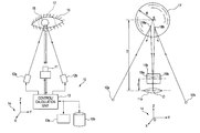
- FIG. 1 is a diagram showing an overall of an apparatus which detects a sight line direction (sight line vector), according to an embodiment of the present invention.
- a sight line detecting apparatus 10 includes a camera 11 , LED (light emitting diode) light sources 12 a and 12 b , a control/calculation unit 13 , an input unit 13 a , and a magnetic disk 13 b.
- Reference numeral 16 indicates one eye of a subject, the sight line of which is detected.
- reference numeral 15 indicates a pupil
- reference numeral 17 indicates a cornea ball.
- the camera 11 is a digital camera, while a focal distance “f” of a lens 11 a of the camera 11 is known.
- FIG. 8A and FIG. 8B are diagrams representing examples of photographed images.
- FIG. 8A is a photographed image in a state that the subject views a substantially horizontal direction
- FIG. 8B is a photographed image in a state that the subject views an upper direction. If a sight line direction (sight line vector) is acquired from a right eye and a left eye of the subject shown in FIG. 8 , then a direction to which the subject pays his or her attention can be detected.
- a sight line direction sight line vector
Landscapes
- Health & Medical Sciences (AREA)
- Life Sciences & Earth Sciences (AREA)
- Engineering & Computer Science (AREA)
- Physics & Mathematics (AREA)
- General Health & Medical Sciences (AREA)
- Ophthalmology & Optometry (AREA)
- Surgery (AREA)
- Public Health (AREA)
- Medical Informatics (AREA)
- Molecular Biology (AREA)
- Biomedical Technology (AREA)
- Animal Behavior & Ethology (AREA)
- Biophysics (AREA)
- Heart & Thoracic Surgery (AREA)
- Veterinary Medicine (AREA)
- Human Computer Interaction (AREA)
- General Physics & Mathematics (AREA)
- Multimedia (AREA)
- Theoretical Computer Science (AREA)
- Eye Examination Apparatus (AREA)
- Fittings On The Vehicle Exterior For Carrying Loads, And Devices For Holding Or Mounting Articles (AREA)
- User Interface Of Digital Computer (AREA)
Abstract
A sight line vector detecting method includes: emitting LED light beams from LED light sources arranged on both sides of a camera to an eye; photographing the eye by the camera; acquiring a plane which includes one light source position of the LED light sources, a lens center position of the camera, and a spatial position on a photographed image as to one luminescent spot on a cornea spherical surface, and another plane which includes the other light source position, the lens center position of the camera, and a spatial position on the photographed image as to the other luminescent spot on the cornea spherical surface; acquiring a line of intersection between the two planes; acquiring a center of a cornea ball which is on the intersection line and satisfies a predetermined condition; and acquiring a center of a pupil.
Description
This application claims foreign priority based on Japanese Patent application No. 2006-029428, filed Feb. 7, 2006, the content of which is incorporated herein by reference in its entirety.
1. Field of the Invention
The present invention is related to a method and an apparatus for detecting a sight line vector of a human. Particularly, the present invention is related to a technique for detecting a sight line direction of a person as, for instance, assisting means for an input unit of a computer or when driving a vehicle.
2. Description of the Related Art
When a person wishes to view a scene or an event, the person turns his or her face and eyes to a direction of the scene or the event. That is, the person turns his or her face and eyes to the direction that the person wishes to see in response to an instruction from a brain, images the desired scene or event on retinas, and then, processes images on the retinas so as to acquire necessary information. In this case, turning the eye means making a normal vector of a pupil of the eye correspond to a desired direction, and it is conceivable that a sight line direction (otherwise, sight line vector) is a half straight line (otherwise, vector) which connects a center point of a cornea ball and a center point of the pupil. As a consequence, in order to detect the sight line direction, the sight line direction is obtained by determining a position (coordinates) of the center point of the cornea ball and a position (coordinates) of the center point of the pupil.
Since a pupil is externally exposed, if a distance from a camera up to the pupil can be measured, then center of the pupil can be easily calculated. For instance, by photographing a pupil, a center of the pupil can be acquired from the photographed image. However, it is difficult to directly measure the distance from the camera up to the pupil. Also, since a center of a cornea ball is not externally exposed, it has been so understood that a calculation of this position is complicated. As a consequence, such a sight line vector detecting method and a sight line vector detecting apparatus which are simple and easily understood have not yet been developed.
In order to acquire the center position of the cornea ball, for instance, it is conceivable that a cornea shape measuring apparatuses for measuring a cornea shape, which is used in a hospital's ophthalmology department, may be utilized. However, as can be easily understood from the techniques described in, for example, JP-A-2003-38442 (cornea shape measuring apparatus) and JP-A-2002-17674 (cornea measuring apparatus), these cornea shape measuring apparatuses are not provided to measure entire shape of the cornea ball, but to measure a surface shape on a front side of the cornea. Therefore, it is difficult to measure the center position of the cornea by these cornea shape measuring apparatuses.
As a method of acquiring a sight line direction, for example, there is one method disclosed by HONDA MOTOR CO., LTD. and GENTECH CORPORATION (US publication No. 2005/0200806 A1, “Line-of-sight detection method and apparatus therefor”). FIG. 9 represents a relationship between a structure of an eyeball and a sight line direction. In FIG. 9 , a cornea 55 is located on the outer surface of an eyeball 50, and the cornea 55 is regarded as a portion of a spherical surface of a cornea ball 56 shown by a dotted line. A center of the cornea ball 56 is indicated as S, and the cornea ball 56 is a virtual shell having a radius R. An iris 58 for adjusting an incident light amount is positioned on the front side of a lens 57, and a portion which can be seen from an opening of the iris 58 is a pupil 59. A half straight line 60 of an arrow which connects the center S of the cornea ball 56 and a center T of the pupil 59 corresponds to a sight line direction (sight line vector). It should be noted that FIG. 9 indicates a photographed image 61 and a light beam which is emitted from an LED light source B and is reflected at a point “P” on the cornea 55 to reach a center O of a camera lens. The method of acquiring the sight line direction described in US publication No. 2005/0200806 A1 utilizes the below-mentioned four assumptions (1) to (4) which are recognized based on morphologically known data (“Anthropometry of the Head and Face”, by L. G. Farkas, Lippincott Williams & Wilkins, 1994). That is, in such a case that, on a face of a subject, a right eye is a point A, a left eye is a point B, and a nose is a point C, the below-mentioned assumptions are made:
- distance (A, C)=distance (B, C)
- ratio {distance (A, B)/distance (A, C)}=1.0833
- distance (A, B)=6.5 cm
- diameter of cornea ball=1.54 cm (radius=7.7 mm).
There is a certain question whether all of the above-described assumptions are correctly applied to all of persons. As a consequence, it is necessary to perform a test on the subject. Also, calculation for acquiring the sight line direction is complicated.
The present invention has been made in view of the above circumstances, and provides a sight line vector detecting method and apparatus, which are capable of acquiring a sight line direction in a simple and clear manner by reducing assumption conditions.
In a first aspect of the invention, a sight line vector detecting method comprises:
- emitting LED (light emitting diode) light beams from LED light sources arranged on both sides of a camera to an eye of a subject;
- photographing the eye of the subject by the camera;
- acquiring a plane which includes one light source position of the LED light sources, a lens center position of the camera, and a spatial position on a photographed image as to one luminescent spot on a cornea spherical surface of the subject;
- acquiring another plane which includes the other light source position of the LED light sources, the lens center position of the camera, and a spatial position on the photographed image as to the other luminescent spot on the cornea spherical surface of the subject;
- acquiring a line of intersection between said two planes;
- acquiring a center position of a cornea ball which is on the intersection line and satisfies a predetermined condition; and
- acquiring a center of a pupil for acquiring the sight line vector.
Accordingly, an accurate sight line vector can be acquired in a simpler method.
In the sight line vector detecting method, the predetermined condition is that a bisector line of an angle between an incident light from the LED light source and a reflection light of the incident light matches with a normal vector that passes through the luminescent spot on the cornea spherical surface.
In the sight line vector detecting method, the center of the pupil is acquired by acquiring an intersection point of a straight line which passes through the lens center of the camera and a center of the pupil on the photographed image, and a spherical surface having a predetermined radius from the center of the cornea ball.
In a second aspect of the invention, a sight line vector detecting apparatus comprises:
- a camera;
- LED (light emitting diode) light sources arranged on both sides of the camera;
- a controller for controlling the camera to photograph luminescent spots on a cornea ball of an eye when the LED light sources are turned ON simultaneously; and
- a calculation processing unit for calculating a center point of the cornea ball by using photographed image data of the camera, and calculating a center point of a pupil by using coordinates of the center point of the cornea ball, so as to acquire the sight line vector.
Accordingly, an accurate sight line vector can be quickly acquired by employing the simpler apparatus.
In the sight line vector detecting apparatus, the LED light sources include two sets of the LED light source, and
- a positional relationship between the two sets of the LED light source and the camera are fixed so as to make up a single unit.
In addition, in accordance with the present invention, there is such an effect that installation of the sight line vector detecting apparatus is easy.
Referring now to drawings, an embodiment of the present invention will be described.
In a step S2, firstly, positions (coordinates) of the images 19 a and 19 b of the luminescent spots 18 a and 18 b in the plane coordinate system are read out from the photographed image on the photographed image plane 11 b, and coordinates of the luminescent spots 19 a and 19 b on the three-dimensional coordinate system (XYZ coordinate system) are obtained by utilizing a focal distance “f” (alternatively, it is also possible to set f=1). Next, a plane 20 is obtained which passes through 3 points, namely, the center O of the lens 11 a, the LED light source 12 a, and the image 19 a of the luminescent spot 18 a. Also, another plane 21 is obtained which passes through 3 points, namely, the center O of the lens 11 a, the LED light source 12 b, and the image 19 b of the luminescent spot 18 b (refer to FIG. 4 ). As indicated in FIG. 4 , the plane 20 contains the luminescent spot 18 a, and a normal vector 22 a at the luminescent spot 18 a. Similarly, the plane 21 contains the luminescent spot 18 b, and a normal vector 22 b at the luminescent spot 18 b. Accordingly, both of the planes 20 and 21 contain a center S of the cornea ball 17.
In a step S3, simultaneous equation of two planes, the plane 20 and the plane 21, are calculated so as to obtain an intersection line 25. A center S of the cornea ball 17 is present on the intersection line (straight line) 25. In a step S4, the XYZ coordinate system is converted into an xyz coordinate system so that the plane 20 corresponds to the sheet of FIG. 5 . In other words, as shown in FIG. 5 , the XYZ coordinate system is rotated so that the origin O stays in its original position, the z axis passes through the center S of the cornea ball 17, and the LED light source 12 a is contained in the xz plane. As a result, a cross section which passes through the center S of the cornea ball 17 appears as a circle 17 a on the sheet of FIG. 5 . Also, the luminescent point 18 a and the image 19 a appear on the sheet of FIG. 5 . Further, the path of the light beam emitted from the LED light source 12 a, and the normal vector 22 a which passes through the luminescent point 18 a appear on the sheet of FIG. 5 .
In a step S5, a distance D (distance between the origin O and the center S of the cornea ball 17) which satisfies the below-mentioned conditions is obtained. It is assumed that a diameter (otherwise, radius) of the cornea ball 17 is already known (namely, diameter=14.8 mm, or radius=7.4 mm). This assumption is recognized as morphologically known data. By using the assumption, the distance D is determined so that an incident angle and a reflection angle at the luminescent point of the cornea ball 17 (cross section 17 a) are identical, and furthermore, reflection light passes through the origin O (or image 19 a). As to the plane 21, the sequential operations of the step S4 and the step S5 are carried out in a similar manner so as to calculate a distance Da. The distance D should originally match with the distance Da. In such a case that these distances D and Da do not match due to a measurement error or the like, an average value of these distances D and Da may be employed as the actual distance D. FIG. 6 is a diagram in which a path of a reflection light beam when a distance (D) between the origin O and the center S of the cornea ball 17 is correct is compared with another path of a reflection light beam when distances (D1 and D2) between the origin O and the center S of the cornea ball 17 are in error. As can be understood from this drawing, the distance D can be obtained by a repetition calculation.
In a step S6, a center 28 of the pupil 15 is calculated. Firstly, coordinates of the center 26 of the pupil are obtained in the original coordinate system 14 from the photographed image plane 11 b. Next, a conversion of the coordinate axes (namely, rotation of coordinate axes) is carried out so that the Z axis passes through the center S of the cornea ball 17. In this case, the X axis (or Y axis) may be arbitrarily determined. The new orthogonal coordinate system whose coordinate axes are converted is defined as a coordinate system (X′, Y′, Z′) 14 b. Then, the coordinates of the pupil center 26 in the coordinate system 14 are converted into the new orthogonal coordinate system 14 b so as to obtain the converted coordinates.
In this case, a spherical surface 27 of the pupil 15 is regarded as a portion of a spherical surface having a radius “r” (r=4.5 mm) and the center S of the cornea ball 17 as a center. This assumption is recognized based on the morphologically known data. FIG. 7 is an explanatory diagram for acquiring a center point 28 of the pupil 15. A half straight line is drawn from a center point of the camera lens 11 a to pass through the center 26 of the pupil on the coordinate system 14 b so as to acquire the intersection point 28 between this half straight line and the spherical surface 27. This intersection point 28 is obtained by solving the simultaneous equation of the equation of the spherical surface 27 and the half straight line. This intersection point 28 corresponds to the center point 28 of the pupil 15.
In a step S7, a sight line direction is acquired. As a consequence, the sight line direction is a vector which passes through the center point 28 of the pupil 15 from the center point S of the cornea ball 17.
Although the embodiment of the present invention has been described in detail based upon the drawings, the technical scope of the present invention is not limited thereto. For example, coordinate axes in the coordinate conversions may be suitably determined. Also, as to a method of the repetition calculation for obtaining the distance D, the above-described calculation method may be alternatively changed.
It will be apparent to those skilled in the art that various modifications and variations can be made to the described preferred embodiments of the present invention without departing from the spirit or scope of the invention. Thus, it is intended that the present invention cover all modifications and variations of this invention consistent with the scope of the appended claims and their equivalents.
Claims (7)
1. A sight line vector detecting method, comprising:
emitting LED (light emitting diode) light beams from LED light sources arranged on both sides of a camera to an eye of a subject;
photographing the eye of the subject by the camera;
acquiring a plane which includes one light source position of the LED light sources, a lens center position of the camera, and a spatial position on a photographed image as to one luminescent spot on a cornea spherical surface of the subject;
acquiring another plane which includes the other light source position of the LED light sources, the lens center position of the camera, and a spatial position on the photographed image as to the other luminescent spot on the cornea spherical surface of the subject;
acquiring a line of intersection between said two planes;
acquiring a center position of a cornea ball which is on the intersection line and satisfies a predetermined condition; and
acquiring a center of a pupil for acquiring the sight line vector.
2. The sight line vector detecting method as claimed in claim 1 , wherein the predetermined condition is that a bisector line of an angle between an incident light from the LED light source and a reflection light of the incident light matches with a normal vector that passes through the luminescent spot on the cornea spherical surface.
3. The sight line vector detecting method as claimed in claim 2 , wherein the center of the pupil is acquired by acquiring an intersection point of a straight line which passes through the lens center of the camera and a center of the pupil on the photographed image, and a spherical surface having a predetermined radius from the center of the cornea ball.
4. The sight line vector detecting method as claimed in claim 1 , wherein the center of the pupil is acquired by acquiring an intersection point of a straight line which passes through the lens center of the camera and a center of the pupil on the photographed image, and a spherical surface having a predetermined radius from the center of the cornea ball.
5. The sight line vector detecting method as claimed in claim 1 , wherein the sight line vector is a vector passing from the center of the cornea ball to the center of the pupil.
6. A sight line vector detecting apparatus, comprising:
a camera;
LED (light emitting diode) light sources arranged on both sides of the camera;
a controller for controlling the camera to photograph luminescent spots on a cornea ball of an eye when the LED light sources are turned ON simultaneously; and
a calculation processing unit for calculating a center point of the cornea ball by using photographed image data of the camera, and calculating a center point of a pupil by using coordinates of the center point of the cornea ball, so as to acquire the sight line vector.
7. The sight line vector detecting apparatus as claimed in claim 6 , wherein the LED light sources include two sets of the LED light source, and
a positional relationship between the two sets of the LED light source and the camera are fixed so as to make up a single unit.
Applications Claiming Priority (2)
| Application Number | Priority Date | Filing Date | Title |
|---|---|---|---|
| JPP.2006-029428 | 2006-02-07 | ||
| JP2006029428A JP4824420B2 (en) | 2006-02-07 | 2006-02-07 | Gaze vector detection method and apparatus |
Publications (2)
| Publication Number | Publication Date |
|---|---|
| US20070189742A1 US20070189742A1 (en) | 2007-08-16 |
| US7771049B2 true US7771049B2 (en) | 2010-08-10 |
Family
ID=38336216
Family Applications (1)
| Application Number | Title | Priority Date | Filing Date |
|---|---|---|---|
| US11/702,910 Expired - Fee Related US7771049B2 (en) | 2006-02-07 | 2007-02-06 | Method and apparatus for detecting sight line vector |
Country Status (3)
| Country | Link |
|---|---|
| US (1) | US7771049B2 (en) |
| JP (1) | JP4824420B2 (en) |
| DE (1) | DE102007006158A1 (en) |
Cited By (14)
| Publication number | Priority date | Publication date | Assignee | Title |
|---|---|---|---|---|
| US20160262614A1 (en) * | 2013-11-28 | 2016-09-15 | JVC Kenwood Corporation | Eye gaze detection supporting device and eye gaze detection supporting method |
| US20170156590A1 (en) * | 2014-08-29 | 2017-06-08 | Alps Electric Co., Ltd. | Line-of-sight detection apparatus |
| WO2018013199A1 (en) * | 2016-07-14 | 2018-01-18 | Magic Leap, Inc. | Iris boundary estimation using cornea curvature |
| US10402649B2 (en) | 2016-08-22 | 2019-09-03 | Magic Leap, Inc. | Augmented reality display device with deep learning sensors |
| US10445881B2 (en) | 2016-09-29 | 2019-10-15 | Magic Leap, Inc. | Neural network for eye image segmentation and image quality estimation |
| US10489680B2 (en) | 2016-10-04 | 2019-11-26 | Magic Leap, Inc. | Efficient data layouts for convolutional neural networks |
| US10521661B2 (en) | 2017-09-01 | 2019-12-31 | Magic Leap, Inc. | Detailed eye shape model for robust biometric applications |
| US10621747B2 (en) | 2016-11-15 | 2020-04-14 | Magic Leap, Inc. | Deep learning system for cuboid detection |
| US10657376B2 (en) | 2017-03-17 | 2020-05-19 | Magic Leap, Inc. | Room layout estimation methods and techniques |
| US10719951B2 (en) | 2017-09-20 | 2020-07-21 | Magic Leap, Inc. | Personalized neural network for eye tracking |
| US10922583B2 (en) | 2017-07-26 | 2021-02-16 | Magic Leap, Inc. | Training a neural network with representations of user interface devices |
| US10922393B2 (en) | 2016-07-14 | 2021-02-16 | Magic Leap, Inc. | Deep neural network for iris identification |
| US11150777B2 (en) | 2016-12-05 | 2021-10-19 | Magic Leap, Inc. | Virtual user input controls in a mixed reality environment |
| US11537895B2 (en) | 2017-10-26 | 2022-12-27 | Magic Leap, Inc. | Gradient normalization systems and methods for adaptive loss balancing in deep multitask networks |
Families Citing this family (13)
| Publication number | Priority date | Publication date | Assignee | Title |
|---|---|---|---|---|
| JP4676375B2 (en) * | 2006-05-10 | 2011-04-27 | アイテック株式会社 | Method or apparatus for detecting direction of sight of vehicle driver |
| JP2009059257A (en) * | 2007-09-03 | 2009-03-19 | Sony Corp | Information processing apparatus and information processing method, and computer program |
| TWI398796B (en) * | 2009-03-27 | 2013-06-11 | Utechzone Co Ltd | Pupil tracking methods and systems, and correction methods and correction modules for pupil tracking |
| US20140043229A1 (en) * | 2011-04-07 | 2014-02-13 | Nec Casio Mobile Communications, Ltd. | Input device, input method, and computer program |
| JP2016049259A (en) * | 2014-08-29 | 2016-04-11 | アルプス電気株式会社 | Visual axis detecting apparatus |
| JP6201956B2 (en) | 2014-10-24 | 2017-09-27 | 株式会社Jvcケンウッド | Gaze detection device and gaze detection method |
| JP6485819B2 (en) * | 2016-07-27 | 2019-03-20 | フォーブ インコーポレーテッド | Gaze detection system, deviation detection method, deviation detection program |
| KR20180060559A (en) * | 2016-11-29 | 2018-06-07 | 삼성전자주식회사 | Method and apparatus for determining inter-pupilary distance |
| JP6403836B1 (en) | 2017-06-08 | 2018-10-10 | 株式会社ナックイメージテクノロジー | Visual function inspection apparatus, visual function training apparatus and method |
| CN107767421B (en) * | 2017-09-01 | 2020-03-27 | 北京七鑫易维信息技术有限公司 | Light spot light source matching method and device in sight tracking equipment |
| KR102499067B1 (en) | 2018-10-08 | 2023-02-10 | 주식회사 엘지화학 | Ink composition for 3d inkjet printing to provide high strength of mechanical properties |
| KR102602511B1 (en) | 2019-02-14 | 2023-11-14 | 주식회사 엘지화학 | Ink composition for 3d inkjet printing to provide excllent toughness |
| SE2250689A1 (en) * | 2022-06-08 | 2023-12-09 | Tobii Ab | Eye profiling |
Citations (4)
| Publication number | Priority date | Publication date | Assignee | Title |
|---|---|---|---|---|
| US6055322A (en) * | 1997-12-01 | 2000-04-25 | Sensor, Inc. | Method and apparatus for illuminating and imaging eyes through eyeglasses using multiple sources of illumination |
| JP2002017674A (en) | 2000-07-10 | 2002-01-22 | Canon Inc | Cornea measuring instrument |
| JP2003038442A (en) | 2001-07-26 | 2003-02-12 | Canon Inc | Cornea shape measuring device |
| US20050200806A1 (en) | 2004-03-12 | 2005-09-15 | Honda Motor Co., Ltd. | Line-of-sight detection method and apparatus therefor |
Family Cites Families (9)
| Publication number | Priority date | Publication date | Assignee | Title |
|---|---|---|---|---|
| JP2739331B2 (en) * | 1988-11-16 | 1998-04-15 | 株式会社エイ・ティ・アール通信システム研究所 | Non-contact gaze detection device |
| JP2939988B2 (en) * | 1989-04-05 | 1999-08-25 | キヤノン株式会社 | Eye gaze detection device |
| JP2939989B2 (en) * | 1989-04-05 | 1999-08-25 | キヤノン株式会社 | Eye gaze detection device |
| JP2995878B2 (en) * | 1991-01-17 | 1999-12-27 | キヤノン株式会社 | Optical device having line-of-sight detection device |
| JPH0694978A (en) * | 1992-09-14 | 1994-04-08 | Nikon Corp | Device for detecting line of sight |
| JPH0694977A (en) * | 1992-09-14 | 1994-04-08 | Nikon Corp | Device for detecting line of sight |
| JPH07299038A (en) * | 1994-05-06 | 1995-11-14 | Nikon Corp | Camera having visual axis detecting function |
| JP3711053B2 (en) * | 2001-09-12 | 2005-10-26 | 日本電信電話株式会社 | Line-of-sight measurement device and method, line-of-sight measurement program, and recording medium recording the program |
| JP2007029126A (en) * | 2005-07-22 | 2007-02-08 | System Artware:Kk | Line-of-sight detecting device |
-
2006
- 2006-02-07 JP JP2006029428A patent/JP4824420B2/en not_active Expired - Fee Related
-
2007
- 2007-02-06 US US11/702,910 patent/US7771049B2/en not_active Expired - Fee Related
- 2007-02-07 DE DE200710006158 patent/DE102007006158A1/en not_active Withdrawn
Patent Citations (5)
| Publication number | Priority date | Publication date | Assignee | Title |
|---|---|---|---|---|
| US6055322A (en) * | 1997-12-01 | 2000-04-25 | Sensor, Inc. | Method and apparatus for illuminating and imaging eyes through eyeglasses using multiple sources of illumination |
| US6252977B1 (en) * | 1997-12-01 | 2001-06-26 | Sensar, Inc. | Method and apparatus for illuminating and imaging eyes through eyeglasses using multiple sources of illumination |
| JP2002017674A (en) | 2000-07-10 | 2002-01-22 | Canon Inc | Cornea measuring instrument |
| JP2003038442A (en) | 2001-07-26 | 2003-02-12 | Canon Inc | Cornea shape measuring device |
| US20050200806A1 (en) | 2004-03-12 | 2005-09-15 | Honda Motor Co., Ltd. | Line-of-sight detection method and apparatus therefor |
Non-Patent Citations (2)
| Title |
|---|
| Editor-Leslie G. Farkas, Anthropometry of the Head and Face, Second Edition, Raven Press, Ltd., 1185 Ave. of the Americas, New York, New York 10036; 1994 Raven Press, Ltd., pp. 272, 275, 288-289 (Appendix A); pp. 341-343, 349(Appendix B; p. 350 (Appendix C); Cover photograph provided by Superstock, Inc., Birth of Venus, Sandra Boticelli. |
| Editor—Leslie G. Farkas, Anthropometry of the Head and Face, Second Edition, Raven Press, Ltd., 1185 Ave. of the Americas, New York, New York 10036; 1994 Raven Press, Ltd., pp. 272, 275, 288-289 (Appendix A); pp. 341-343, 349(Appendix B; p. 350 (Appendix C); Cover photograph provided by Superstock, Inc., Birth of Venus, Sandra Boticelli. |
Cited By (33)
| Publication number | Priority date | Publication date | Assignee | Title |
|---|---|---|---|---|
| US9993154B2 (en) * | 2013-11-28 | 2018-06-12 | JVC Kenwood Corporation | Eye gaze detection supporting device and eye gaze detection supporting method |
| US20160262614A1 (en) * | 2013-11-28 | 2016-09-15 | JVC Kenwood Corporation | Eye gaze detection supporting device and eye gaze detection supporting method |
| US20170156590A1 (en) * | 2014-08-29 | 2017-06-08 | Alps Electric Co., Ltd. | Line-of-sight detection apparatus |
| US11568035B2 (en) | 2016-07-14 | 2023-01-31 | Magic Leap, Inc. | Deep neural network for iris identification |
| US10922393B2 (en) | 2016-07-14 | 2021-02-16 | Magic Leap, Inc. | Deep neural network for iris identification |
| WO2018013199A1 (en) * | 2016-07-14 | 2018-01-18 | Magic Leap, Inc. | Iris boundary estimation using cornea curvature |
| US10296792B2 (en) | 2016-07-14 | 2019-05-21 | Magic Leap, Inc. | Iris boundary estimation using cornea curvature |
| US11120266B2 (en) | 2016-08-22 | 2021-09-14 | Magic Leap, Inc. | Augmented reality display device with deep learning sensors |
| US11797078B2 (en) | 2016-08-22 | 2023-10-24 | Magic Leap, Inc. | Augmented reality display device with deep learning sensors |
| US10733447B2 (en) | 2016-08-22 | 2020-08-04 | Magic Leap, Inc. | Augmented reality display device with deep learning sensors |
| US10402649B2 (en) | 2016-08-22 | 2019-09-03 | Magic Leap, Inc. | Augmented reality display device with deep learning sensors |
| US11776131B2 (en) | 2016-09-29 | 2023-10-03 | Magic Leap, Inc. | Neural network for eye image segmentation and image quality estimation |
| US11100644B2 (en) | 2016-09-29 | 2021-08-24 | Magic Leap, Inc. | Neural network for eye image segmentation and image quality estimation |
| US10445881B2 (en) | 2016-09-29 | 2019-10-15 | Magic Leap, Inc. | Neural network for eye image segmentation and image quality estimation |
| US10489680B2 (en) | 2016-10-04 | 2019-11-26 | Magic Leap, Inc. | Efficient data layouts for convolutional neural networks |
| US11182645B2 (en) | 2016-10-04 | 2021-11-23 | Magic Leap, Inc. | Efficient data layouts for convolutional neural networks |
| US11720800B2 (en) | 2016-10-04 | 2023-08-08 | Magic Leap, Inc. | Efficient data layouts for convolutional neural networks |
| US10937188B2 (en) | 2016-11-15 | 2021-03-02 | Magic Leap, Inc. | Deep learning system for cuboid detection |
| US11797860B2 (en) | 2016-11-15 | 2023-10-24 | Magic Leap, Inc. | Deep learning system for cuboid detection |
| US10621747B2 (en) | 2016-11-15 | 2020-04-14 | Magic Leap, Inc. | Deep learning system for cuboid detection |
| US11328443B2 (en) | 2016-11-15 | 2022-05-10 | Magic Leap, Inc. | Deep learning system for cuboid detection |
| US11720223B2 (en) | 2016-12-05 | 2023-08-08 | Magic Leap, Inc. | Virtual user input controls in a mixed reality environment |
| US11150777B2 (en) | 2016-12-05 | 2021-10-19 | Magic Leap, Inc. | Virtual user input controls in a mixed reality environment |
| US11775835B2 (en) | 2017-03-17 | 2023-10-03 | Magic Leap, Inc. | Room layout estimation methods and techniques |
| US10657376B2 (en) | 2017-03-17 | 2020-05-19 | Magic Leap, Inc. | Room layout estimation methods and techniques |
| US10922583B2 (en) | 2017-07-26 | 2021-02-16 | Magic Leap, Inc. | Training a neural network with representations of user interface devices |
| US11334765B2 (en) | 2017-07-26 | 2022-05-17 | Magic Leap, Inc. | Training a neural network with representations of user interface devices |
| US11630314B2 (en) | 2017-07-26 | 2023-04-18 | Magic Leap, Inc. | Training a neural network with representations of user interface devices |
| US11227158B2 (en) | 2017-09-01 | 2022-01-18 | Magic Leap, Inc. | Detailed eye shape model for robust biometric applications |
| US10521661B2 (en) | 2017-09-01 | 2019-12-31 | Magic Leap, Inc. | Detailed eye shape model for robust biometric applications |
| US10977820B2 (en) | 2017-09-20 | 2021-04-13 | Magic Leap, Inc. | Personalized neural network for eye tracking |
| US10719951B2 (en) | 2017-09-20 | 2020-07-21 | Magic Leap, Inc. | Personalized neural network for eye tracking |
| US11537895B2 (en) | 2017-10-26 | 2022-12-27 | Magic Leap, Inc. | Gradient normalization systems and methods for adaptive loss balancing in deep multitask networks |
Also Published As
| Publication number | Publication date |
|---|---|
| JP2007209384A (en) | 2007-08-23 |
| JP4824420B2 (en) | 2011-11-30 |
| US20070189742A1 (en) | 2007-08-16 |
| DE102007006158A1 (en) | 2007-09-13 |
Similar Documents
| Publication | Publication Date | Title |
|---|---|---|
| US7771049B2 (en) | Method and apparatus for detecting sight line vector | |
| US7246904B2 (en) | Line-of-sight detection method and apparatus therefor | |
| US8371693B2 (en) | Autism diagnosis support apparatus | |
| JP2020034919A (en) | Eye tracking using structured light | |
| US10499808B2 (en) | Pupil detection system, gaze detection system, pupil detection method, and pupil detection program | |
| US8885177B2 (en) | Medical wide field of view optical tracking system | |
| KR20210107015A (en) | Head mounted display calibration using a portable docking station with a calibration target | |
| EP0596868B1 (en) | Eye tracking method using an image pickup apparatus | |
| US20090015788A1 (en) | Sight Line Detecting Method | |
| WO2005063114A1 (en) | Sight-line detection method and device, and three- dimensional view-point measurement device | |
| JP2005185431A (en) | Line-of-sight detection method and line-of-sight detector | |
| EP3542308B1 (en) | Method and device for eye metric acquisition | |
| JP7030317B2 (en) | Pupil detection device and pupil detection method | |
| US20130120712A1 (en) | Method and device for determining the eye position | |
| JPH02138673A (en) | Image pickup device | |
| JP7168953B2 (en) | Gaze measurement device for automatic calibration, Gaze measurement method and Gaze measurement program | |
| JP4500992B2 (en) | 3D viewpoint measuring device | |
| EP0373788A2 (en) | Ocular refracting power measuring system | |
| JP6948688B2 (en) | Line-of-sight measurement device, line-of-sight measurement method, and line-of-sight measurement program | |
| WO2018164104A1 (en) | Eye image processing device | |
| CN113260299A (en) | System and method for eye tracking | |
| US11435820B1 (en) | Gaze detection pipeline in an artificial reality system | |
| JP6555707B2 (en) | Pupil detection device, pupil detection method, and pupil detection program | |
| JP2019098024A (en) | Image processing device and method | |
| JP6430813B2 (en) | Position detection apparatus, position detection method, gazing point detection apparatus, and image generation apparatus |
Legal Events
| Date | Code | Title | Description |
|---|---|---|---|
| AS | Assignment |
Owner name: HONDA MOTOR CO., LTD., JAPAN Free format text: ASSIGNMENT OF ASSIGNORS INTEREST;ASSIGNORS:KNAAN, DOTAN;SHAVIT, ADI;SHAVIT, DANA;AND OTHERS;REEL/FRAME:019226/0902 Effective date: 20070413 |
|
| FEPP | Fee payment procedure |
Free format text: PAYOR NUMBER ASSIGNED (ORIGINAL EVENT CODE: ASPN); ENTITY STATUS OF PATENT OWNER: LARGE ENTITY |
|
| REMI | Maintenance fee reminder mailed | ||
| LAPS | Lapse for failure to pay maintenance fees | ||
| STCH | Information on status: patent discontinuation |
Free format text: PATENT EXPIRED DUE TO NONPAYMENT OF MAINTENANCE FEES UNDER 37 CFR 1.362 |
|
| FP | Lapsed due to failure to pay maintenance fee |
Effective date: 20140810 |