US7738902B2 - Transmission power control method - Google Patents
Transmission power control method Download PDFInfo
- Publication number
- US7738902B2 US7738902B2 US10/862,611 US86261104A US7738902B2 US 7738902 B2 US7738902 B2 US 7738902B2 US 86261104 A US86261104 A US 86261104A US 7738902 B2 US7738902 B2 US 7738902B2
- Authority
- US
- United States
- Prior art keywords
- quality
- target
- sir
- power
- measured
- Prior art date
- Legal status (The legal status is an assumption and is not a legal conclusion. Google has not performed a legal analysis and makes no representation as to the accuracy of the status listed.)
- Expired - Fee Related, expires
Links
Images


Classifications
-
- H—ELECTRICITY
- H04—ELECTRIC COMMUNICATION TECHNIQUE
- H04W—WIRELESS COMMUNICATION NETWORKS
- H04W52/00—Power management, e.g. TPC [Transmission Power Control], power saving or power classes
- H04W52/04—TPC
- H04W52/18—TPC being performed according to specific parameters
- H04W52/24—TPC being performed according to specific parameters using SIR [Signal to Interference Ratio] or other wireless path parameters
- H04W52/248—TPC being performed according to specific parameters using SIR [Signal to Interference Ratio] or other wireless path parameters where transmission power control commands are generated based on a path parameter
-
- H—ELECTRICITY
- H04—ELECTRIC COMMUNICATION TECHNIQUE
- H04W—WIRELESS COMMUNICATION NETWORKS
- H04W52/00—Power management, e.g. TPC [Transmission Power Control], power saving or power classes
- H04W52/04—TPC
- H04W52/06—TPC algorithms
- H04W52/12—Outer and inner loops
-
- H—ELECTRICITY
- H04—ELECTRIC COMMUNICATION TECHNIQUE
- H04W—WIRELESS COMMUNICATION NETWORKS
- H04W52/00—Power management, e.g. TPC [Transmission Power Control], power saving or power classes
- H04W52/04—TPC
- H04W52/18—TPC being performed according to specific parameters
- H04W52/24—TPC being performed according to specific parameters using SIR [Signal to Interference Ratio] or other wireless path parameters
- H04W52/241—TPC being performed according to specific parameters using SIR [Signal to Interference Ratio] or other wireless path parameters taking into account channel quality metrics, e.g. SIR, SNR, CIR, Eb/lo
-
- H—ELECTRICITY
- H04—ELECTRIC COMMUNICATION TECHNIQUE
- H04W—WIRELESS COMMUNICATION NETWORKS
- H04W52/00—Power management, e.g. TPC [Transmission Power Control], power saving or power classes
- H04W52/04—TPC
- H04W52/30—TPC using constraints in the total amount of available transmission power
- H04W52/32—TPC of broadcast or control channels
Definitions
- This invention relates to a transmission power control method and, more particularly, to a transmission power control method in a wireless communication system for controlling transmission power on the transmitting side in such a manner that measured reception quality will agree with a target reception quality.
- W-CDMA Wideband-Code Division Multiple Access
- multiple channels are distinguished from one another by spreading codes assigned to the channels, thereby allowing communication by multiple channels sharing a single frequency band.
- a receive signal is susceptible to interference from its own channel and from other channels owing to delayed waves ascribable to multipath fading and radio waves from other cells, and this interference has an adverse influence upon channel separation.
- the amount of interference sustained by a receive signal varies with time owing to momentary fluctuations in reception power ascribable to multipath fading and changes in the number of users communicating simultaneously.
- SIR signal-to-interference ratio
- FIG. 9 is a diagram useful in describing inner-loop transmission power control. Here only one channel of the system is illustrated.
- a spread-spectrum modulator 1 a of a base station 1 spread-spectrum modulates transmit data using a spreading code conforming to a specified channel.
- the spread-spectrum modulated signal is subjected to processing such as orthogonal modulation and frequency conversion and the resultant signal is input to a power amplifier 1 b, which amplifies this signal and transmits the amplified signal toward a mobile station 2 from an antenna.
- a despreading unit 2 a in the receiver of the mobile station applies despread processing to the receive signal and a demodulator 2 b demodulates the receive data.
- a SIR measurement unit 2 c measures the power ratio between the receive signal and an interference signal and a comparator 2 d compares target SIR and measured SIR. If the measured SIR is greater than the target SIR, the comparator 2 d creates a command that lowers the transmission power by a TPC (Transmission Power Control) bit. If the measured SIR is less than the target SIR, on the other hand, the comparator 2 d creates a command that raises the transmission power by the TPC bits.
- the target SIR is a SIR value necessary to obtain, e.g., 10 ⁇ 3 (error occurrence at a rate of once every 1000 times). This value is input to the comparator 2 d from a target-SIR setting unit 2 e.
- the mobile station 2 subjects the signal to processing such as a DA conversion, orthogonal modulation, frequency conversion and power amplification and transmits the resultant signal toward the base station 1 from an antenna.
- a despreading unit 1 c on the side of the base station applies despread processing to the signal received from the mobile station 2 , and a demodulator 1 d demodulates the receive data and TPC bits and controls the transmission power of the base station 1 in accordance with a command specified by the TPC bits.
- FIG. 10 is a diagram showing the structure of an uplink DPCH (Dedicated Physical Channel) frame standardized by the 3 rd Generation Partnership Project (referred to as “3GPP” below).
- DPCH Downlink Physical Channel
- 3GPP 3 rd Generation Partnership Project
- One frame of the uplink has a duration of 10 ms and is composed of 15 slots (slot # 0 to slot # 14 ).
- the DPDCH channel is mapped to an orthogonal I channel and the DPCCH channel is mapped to an orthogonal Q channel.
- Each slot of the DPDCH channel consists of n bits, and the n varies in accordance with the symbol rate.
- Each slot of the DPCCH channel that transmits the control data consists of ten bits, has a symbol rate of 15 ksps and transmits a pilot PILOT, transmission power control data TPC, a transport format combination indicator TFCI and feedback information FBI.
- BLER block error rate
- FIG. 11 is a block diagram of well-known outer-loop control.
- a signal that has been transmitted from the base station 1 is decoded by an error correcting decoder 4 a after it is demodulated by the demodulator 2 b.
- the decoded signal is then applied to a CRC detector 4 b where it is divided into transport blocks TrBk and subsequently subjected to CRC error detection on a per-TrBk basis.
- the result of error detection applied to each transport block TrBk is sent to target-SIR controller 4 c.
- encoding is performed on the transmitting side in the manner shown in FIG. 12 .
- a CRC add-on circuit on the transmitting side generates a CRC (Cyclic Redundancy Code) error detection code for every transport block TrBk and adds this onto the transmit data.
- An encoder on the transmitting side joins the N-number of transport blocks TrBk having the attached CRCs and encodes the blocks by error correcting coding such as convolutional coding or turbo coding.
- the error correcting decoder 4 a subjects the receive data to error-correction decoding processing and inputs the result of decoding to the CRC detector 4 b, and the CRC detector 4 b performs CRC error detection for every transport block TrBk constituting the result of decoding and inputs the results of error detection to the target-SIR controller 4 c.
- a host application specifies the required BLER that conforms to the service type of the DCH, such as voice, packet or unrestricted digital.
- BLERquality represent the required BLER
- Tmax represent the number of transport blocks TrBk for which BLER is measured
- Sinc (dB) represent an update quantity for raising the target SIR in a case where the measured BLER is inferior to the required BLER
- Sdec (dB) represent an update quantity for lowering the target SIR in a case where the measured BLER is superior to the required BLER.
- the target SIR is updated by Sinc. If CRC OK holds throughout, the target SIR is updated by Sdec. When this is observed in total, the target SIR settles stabilizes at a fixed level. This is the fundamental concept of outer-loop control.
- (1 ⁇ BLER quality ) Tmax ⁇ Sdec [1 ⁇ (1 ⁇ BLER quality ) Tmax ] ⁇ Sinc (1)
- (1 ⁇ BLER quality ) Tmax indicates the probability that the CRC check will be correct Tmax-times in succession
- [1 ⁇ (1 ⁇ BLER quality ) Tmax ] indicates the probability that there will be even one CRC check error in Tmax times.
- BLER measurement is performed with regard to Tmax-number of transport blocks TrBk. If CRC OK is obtained for all TrBk, the target SIR is updated by Sdec. If there is even one CRC NG (CRC error), then the target SIR is updated by Sinc.
- the values of Sinc, Sdec and Tmax are values uniquely decided by the required BLER of each service.
- the initial value of the target SIR is the same for all bearers (all services).
- a point that is positively above a convergence point (the convergence target SIR) is set as the initial target SIR beforehand.
- the target SIR is updated based upon this result. More specifically, if an error is not detected whenever a CRC check is performed, the target SIR is reduced a prescribed value at a time starting from the initial target SIR.
- the error rate is measured at a target-SIR update period T that conforms to the service, this measured error rate is compared with a required error rate and the target SIR is updated accordingly.
- a CRC result is ascertained every 10 ms and the target-SIR update period becomes 10 ms.
- the incremental amount of updating is made a relatively large value so as to detect CRC NG quickly, e.g., a value on the order of ⁇ 1 dB, which is a value that is ten times the usual.
- Outer-loop control from the initial value of the target SIR to detection of CRC NG shall be referred to as the “initial state”.
- the power of the DPCH (Dedicated Physical Channel) of the local station is the desired wave power and is defined as DPCH_RSCP [RSCP: Received Signal Code Power (dBm)].
- DPCH_RSCP Received Signal Code Power
- interference waves of a common pilot channel (CPICH: Common Pilot Channel) of other stations not orthogonal to the local DPCH and of the DPCH_RSCP of other stations are defined as ISCP [Interference Signal Code Power (dBm)].
- total power (referred to as overall reception power) with respect to all receive signals obtained by despreading the common pilot channel (CPICH) of local/other stations and the dedicated physical channel (DPCH) is defined as RSSI (Received Signal Strength Indicator).
- SIR ( DPCH — RSCP ⁇ ISCP ) ⁇ SF (dB) (3)
- the downlink (the link from the base station to the mobile station) DPCH frame has a frame period of 10 ms, which is divided into 15 slots, as shown in FIG. 14 .
- the spreading factor SF in Equation (3) has a constant value from the connection of a call to the end of the call.
- the measured SIR is obtained by measuring the value of DPCH_RSCP and the value of ISCP and performing the calculation of Equation (3).
- transmission power control information to the effect that the transmission power is to be lowered is inserted at a prescribed position (the TPC bits) of the DPCCH from the mobile station to the base station. Conversely, if the measured SIR is lower than the target SIR, then transmission power control information to the effect that the transmission power is to be raised is inserted. Transmission power control in the downlink direction is performed upon inserting the proper transmission power control information.
- Japanese Patent Application Laid-Open No. 2003-18089 proposes varying the amount of updating of a target value adaptively in accordance with changes in the propagation environment, thereby maintaining a desired reception quality irrespectively of the magnitude of any change in propagation environment.
- Japanese Patent Application Laid-Open No. 2003-78484 proposes shortening the time it takes to achieve convergence following the start of transmission power when downlink transmission power control has been carried out.
- the value of DPCH_RSCP used in the calculation of Equation (3) is a value of the power of the receive-signal DPCH pilot bits of the local station, and the value of ISCP is Equation (3) indicates the value of interference power of other stations, etc.
- the value of DPCH_RSCP becomes predominant in the measured value of SIR.
- FIG. 15 is a table useful in describing slot formats of the downlink DPCH.
- the table illustrates, for every slot format specified by a slot format number, the relationship between spreading factor SF and number of data bits, TPC bits, TFCI bits and pilot bits per slot and the proportion occupied by the spreading factor SF.
- Downlink power (the transmission power of the base station) can be varied on a per-slot basis by TPC control on the side of the mobile station. This will be considered while excluding the effects thereof. Further, it will be assumed that the initial value of downlink power is constant even in a case where the spreading factor SF differs, and that there is no power offset of DPCCH (TPC, TFCI, Pilot) with respect to DPDCH power. In such case the downlink power per slot will be constant even in a case where the spreading factor SF differs and therefore the power allocated to the pilot bits will be proportional to the pilot ratio.
- T represent the duration of measurement, BLERquality the required BLER over this period, Sinc_total the total update value on the + side in the measurement period T and Sdec_total the total update value on the ⁇ side in the measurement period T.
- Sinc, Sdec represent the amount of update per time
- (1 ⁇ BLERquality) T is the probability that CRC NG will not appear at all over the time T
- 1 ⁇ (1 ⁇ BLERquality) T is the probability that CRC NG will appear one or more times over the time T, and therefore Equation (6) below holds.
- (Sdec, which is the update quantity on the ⁇ side represents the absolute value of the actual amount of decrease.
- Sdec
- 0.1 in case of ⁇ 0.1 dB.
- Sdec _total/ Sinc _total ⁇ [(1 ⁇ BLER quality ) T ] ⁇ Sdec ⁇ / ⁇ [(1 ⁇ (1 ⁇ BLER quality ) T )] ⁇ Sinc ⁇ (6)
- T is small means that the observation period of BLER is short, or in other words, that updating of target SIR is performed frequently in order to acquire the required BLER when there is a large SIR variance.
- the value of Sdec_total/Sinc_total becomes large. That is, the total value of decrease update on the ⁇ side is larger than the total value of increase update on the + side.
- control information to the effect that call connection is to be performed is transmitted from the side of the base station to the side of the mobile station on the DCCH (Dedicated Control Channel).
- the target SIR attains the stable state upon exceeding a CRC-NG occurrence level L C of the DCCH, in which the data is a single shot, and arrives at a level L D at which CRC NG occurs on DTCH, where the data is continuous. Since the DCCD control data is sent and received when the initial state prevails, there is a possibility that some of the necessary data will not be acquired depending upon the communication bearer (service) in the region where the target SIR is less than L C . This represents a second problem encountered in the prior art.
- a first object of the present invention is to prevent transmission power from a base station from becoming excessive even if power allocated to pilot bits diminishes and an error occurs in SIR measurement.
- a second object of the present invention is to enable the acquisition of DCCH control data following connection of a call and prevent transmission power from a base station from becoming excessive.
- a third object of the present invention is to lower target SIR rapidly and prevent transmission power from a base station from becoming excessive at departure from a shadowing state.
- a transmission power control method in a wireless communication system in which power allocated to a pilot signal can be varied to at least a first power and a second power, comprising the steps of: measuring reception quality using power of a receive pilot signal and power of an interference signal thereof when reception quality is measured with regard to whichever of the larger of the first power and second power is allocated to the pilot signal; measuring reception quality using the power of the receive pilot signal and a reception power that includes at least another signal portion in addition to the pilot signal when reception quality is measured with regard to whichever of the smaller of the first power and second power is allocated to the pilot signal; and sending a transmission power control signal to a transmitting side in such a manner that the measured reception quality will agree with a target reception quality.
- a transmission power control method in a wireless communication system for controlling transmission power on a transmitting side in such a manner that measured reception quality will agree with a target reception quality comprising the steps of: measuring reception quality using power of a receive pilot signal and power of an interference signal thereof when a receive signal has a large spreading factor; measuring reception quality using the power of the receive pilot signal and overall reception power when a receive signal has a small spreading factor; and sending a transmission power control signal to the transmitting side in such a manner that measured reception quality will agree with a target reception quality.
- first and second methods of calculating reception quality are provided.
- the reception-quality measurement error is reduced using the second method of calculation.
- downlink transmission power from a base station can be prevented from becoming excessive. In other words, excessive power demanded for the downlink can be reduced.
- a transmission power control method in a wireless communication system for controlling transmission power on a transmitting side in such a manner that measured quality will agree with a target quality comprising the steps of: ⁇ circle around (1) ⁇ if a high-quality service call is made, setting the target quality to be larger than a convergence value so as to satisfy an initial pull-in characteristic, reducing the target quality a prescribed amount if no error is detected whenever an error detection check is made and, when an error has detected, thenceforth measuring error rate at a target-quality update period that conforms to service quality, comparing the error rate measured and a required error rate, and updating the target quality; ⁇ circle around (2) ⁇ if a low-quality service call is made, setting the target quality to be larger than a value at which a dedicated control channel can be decoded correctly, measuring error rate at a target-quality update period that conforms to service quality, comparing the error rate measured and a required error rate, and updating
- failure to acquire DCCH control data after call connection is eliminated with regard to a low-quality service call by the control of step ⁇ circle around (2) ⁇ , and downlink transmission power from a base station can be prevented from becoming excessive with regard to a high-quality service call by the control of step ⁇ circle around (1) ⁇ .
- a transmission power control method in a wireless communication system for comparing a measured error rate and a required error rate, updating a target quality and controlling transmission power on a transmitting side in such a manner that measured quality will agree with the target quality, comprising the steps of: detecting that degradation in quality of a receive signal is continuous; after the continuous degradation in quality is detected, detecting that a state in which measured quality is high is continuous; and setting target quality to an initial value when high quality has been detected continuously.
- the method may include a further step after the initial value is set, namely ⁇ circle around (4) ⁇ a step of reducing the target quality a prescribed amount from the initial value if no error is detected whenever an error detection check is made and, when an error has been detected, thenceforth measuring error rate at a target-quality update period that conforms to service quality, comparing the error rate measured and a required error rate, and updating the target quality.
- the fourth embodiment is such that when a shadowing state is departed from, target quality is lowered rapidly so that downlink transmission power from a base station can be prevented from becoming excessive.
- FIG. 1 is a block diagram illustrating a transmission power control apparatus according to a first embodiment of the present invention
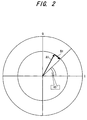
- FIG. 2 is a diagram useful in describing a method of calculating an ISCP value
- FIG. 3 is a diagram useful in describing a second embodiment of the present invention.
- FIG. 4 is a block diagram illustrating a transmission power control apparatus according to the second embodiment
- FIG. 5 is a flowchart of processing according to the second embodiment
- FIG. 6 is a table illustrating the relationship between bearers and required qualities
- FIG. 7 is a flowchart of processing according to a third embodiment relating to excessive demand for downlink power during communication using a high-quality bearer
- FIGS. 8A and 8B illustrate actual examples of control of target SIR according the third embodiment
- FIG. 9 is a diagram for describing inner-loop transmission power control according to the prior art.
- FIG. 10 is a diagram showing the structure of an uplink dedicated physical channel (DPCH) frame according to the prior art
- FIG. 11 is a block diagram of well-known outer-loop control according to the prior art.
- FIG. 12 is a diagram useful in describing encoding in W-CDMA according to the prior art.
- FIG. 13 is a diagram useful in describing control of target SIR according to the prior art.
- FIG. 14 illustrates a DPCH frame on a downlink from a base station to a mobile station according to the prior art
- FIG. 15 is a table for describing the slot formats of a downstream DPCH according to the prior art.
- FIGS. 16A and 16B are diagrams useful in describing a problem in the prior art relating to shadowing.
- the RSSI value is the total power (overall reception power) with respect to all receive signals obtained by despreading the common pilot channel (CPICH) of local/other stations and the dedicated physical channels (DPCH).
- the RSSI value is the total power obtained by superimposing CPICH power, DPCH_RSCP and interference power. Even if fluctuation in the value of a certain single factor is large, therefore, the amount of fluctuation is small. For example, even if the power allocated to pilot bits is small and a DPCH_RSCP measurement error occurs, there is but little fluctuation in the RSSI value. Further, since the RSSI value becomes the denominator in Equation (6), the absolute value of the denominator is large in comparison with Equation (3), and fluctuation of the SIR value is small even if fluctuation of DPCH_RSCP is large.
- the first embodiment is such that SIR is measured using Equation (3) if the spreading factor SF is large and using Equation (6) if the spreading factor SF is small.
- Equation (3) is more sensitive to changes in DPCH_RSCP and ISCP than Equation (6), and so if the errors in these values are small, SIR can be measured more accurately by Equation (3).
- FIG. 1 is a block diagram illustrating a transmission power control in WCDMA mobile communication system apparatus according to the first embodiment.
- a radio unit 11 of a mobile station receives a signal transmitted from a base station, subjects the signal to a frequency conversion and orthogonal detection to obtain a baseband signal and inputs the signal to a despreader 12 .
- the latter subjects the receive signal to despread processing to despread the signal and obtain symbol data.
- the despreader 12 subjects CPICH and DPCH to despreading using a scrambling code that differs for every base station and a channelization code that differs for every user and output I/Q complex symbol data.
- the receive data that undergoes despreading is that of the CPICH of local/other stations and of the DPCH of the local station.
- a synchronous detector 13 extracts data, TPC, TFCI and pilot in each slot from the despread symbol data, executes averaging of pilot symbols in each slot, performs a power-value calculation by complex multiplication, calculates the CPICH_RSCP value, DPCH_RSCP value and ISCP value and inputs these values to a SIR measurement unit 14 .
- a mobile station despreads and monitors the CPICH of each cell at all times and obtains each CPICH_RSCP value by complex multiplication of the I, Q signals of each CPICH. Further, the mobile station recognizes the current cell of residence at the time of an outgoing call from the side of the mobile station or at the time of an incoming call from a base station, despreads the DPCH on the basis of the CPICH information of the current cell of residence, performs a power calculation by complex multiplication with respect to this DPCH and finds the DPCH_RSCP value.
- the degree of variance from a fixed point in an I, Q signal constellation of the DPCH is the interference power of CPICH or DPCH from another station with respect to a non-orthogonal signal, and the value of interference power is adopted as the ISCP value.
- FIG. 2 is a diagram useful in describing a method of calculating the ISCP value. Assume that when a receive pilot symbol obtained by despreading a desired wave is expressed in the I, Q complex plane, it will be a vector A 1 in the first quadrant. Though the vector should rightfully appear at an angle of 450, it is shifted from this angle by reason of interference, etc. In such case the power DPCH_RSCP value of the desired wave becomes the length of the vector A 1 , and the power ISCP of the interference becomes the length of a vector B 1 .
- a spread-spectrum modulator 18 spread-spectrum modulates the transmit data (voice, UDI, packet data, etc.) and control data (TPC, TFCI, pilot, FBI), which been encoded by an encoder 19 , as I, Q signals, respectively.
- a radio unit 20 subjects the spread-spectrum modulated signal to processing such as orthogonal modulation, frequency conversion and power amplification and transmits the resultant signal toward the base station from an antenna.
- the base station applies despread processing to the signal received from the mobile station, demodulates the receive data and TPC bits and controls the transmission power of a transmission power amplifier in accordance with a command specified by the TPC bits.
- the foregoing is inner-loop control and is executed at the slot period.
- a decoder 21 subjects the demodulated data (symbol data having a soft-decision bit width) to deinterleave processing and error-correction decode processing based upon Viterbi decoding or turbo decoding, restores repetitious or punctured bits to the original by rate matching processing and inputs the results of decoding to a CRC checker (CRC detector) 22 .
- CRC checker CRC detector
- the CRC detector 22 performs CRC error detection for every transport block TrBk using the results of decoding and inputs the result of error detection to a BLER measurement unit 23 .
- the target-SIR update controller 24 compares the measured BLER with a required BLER that enters from the higher-layer application 15 and increases or decreases the target SIR based upon the comparison. Specifically, control is exercised so as to increase the target SIR a prescribed amount if the measured BLER is inferior to the target BLER and decrease the target SIR a prescribed amount if the measured BLER is superior to the target BLER.
- the foregoing is outer-loop control and is executed at the predetermined time period T, which is longer than the slot period.
- first and second methods of calculating measured SIR are provided.
- the measurement error is reduced using the second method of calculating measured SIR.
- measured SIR is calculated above in accordance with Equations (3), (6) based upon magnitude of the spreading factor SF, it can be so arranged that measured SIR is calculated in accordance with Equations (3), (6) based upon magnitude of the power allocated to the pilot bits.
- control for updating target SIR is always carried out until CRC NG (where “NG” represents “No Good”) is detected in the initial state when a call is connected. Consequently, there is a heightened possibility that some of the control data (DCCH control data) will not be acquired when the initial state prevails. Accordingly, in the second embodiment, as shown in FIG.
- a target-SIR update period T 1 will be comparatively short and therefore the target SIR will diminish and converge in a short time, as indicated by the solid line in FIG. 3 .
- a target-SIR update period T 2 will be long and therefore the target SIR will be greater than the converged SIR over an extended period of time, as indicated by the dashed line in FIG. 3 .
- the fact that target SIR is greater than the converged SIR means that downlink power (base-station transmission power) is being demanded excessively. In a case where the required BLER is of a high-quality bearer, therefore, excess power indicated by the hatching in FIG. 3 is being demanded.
- the second embodiment is such that in relation to a low-quality bearer, the conventional initial state is eliminated and outer-loop control is performed starting from a steady state in which the update period is relaxed ( FIG. 3 ). In relation to a high-quality bearer, control in which there is a transition from the initial state to the steady state is performed just as in the prior art ( FIG. 13 ).
- FIG. 4 is a block diagram illustrating a transmission power control apparatus according to the second embodiment
- FIG. 5 is a flowchart of processing according to the second embodiment.
- Components in FIG. 4 identical with those of the first embodiment of FIG. 1 are designated by like reference characters.
- This embodiment differs from the first embodiment in that ⁇ circle around (1) ⁇ the SIR measurement unit 14 calculates the measured SIR based solely upon Equation (3), and ⁇ circle around (2) ⁇ the target-SIR update controller 24 updates the target SIR in accordance with the flowchart of FIG. 5 .
- Control for updating the target SIR will be described in accordance with the flowchart of FIG. 5 .
- Control for updating target SIR is of two types, namely initial-state control and steady-state control. These states are managed by a flag operation, in which an OFF flag indicates that initial-state control is in effect and an ON flag that steady-state control is in effect.
- the gist of control is that the initial value of the state flag at the start of outer-loop control following connection of a call is made OFF (step 101 ). Then, during outer-loop control, processing from step 102 onward is executed periodically and call disconnect (step 106 ), etc., is taken as an opportunity to break off processing.
- the target-SIR update controller 24 checks to determine whether the state flag is OFF (step 102 ). Since the state flag initially is OFF, the target-SIR update controller 24 next checks to determine whether the required quality is that of a high- or low-quality service (step 103 ). If the required quality is high, control of target SIR in accordance with FIG. 13 is carried out. If the required quality is low, then control of target SIR in accordance with FIG. 3 is performed.
- step 104 it is determined whether initial-stage control has ended, i.e., whether CRC NG has occurred (step 105 ). If CRC NG has not occurred, it is determined whether the call has been disconnected (step 106 ). If the call has not been disconnected, the processing of steps 102 to 106 is repeated.
- the target-SIR update controller 24 terminates initial-state control and turns the state flag ON (step 107 ).
- the target-SIR update controller 24 checks to see whether the call has been disconnected (step 106 ). Control returns to step 102 if the call has not been disconnected. Now the state flag is ON and the target-SIR update controller 24 thenceforth controls the target SIR by steady-state control (step 108 ).
- the target-SIR update controller 24 determines whether the call has been disconnected (step 106 ). If the call has not been disconnected, the target-SIR update controller 24 continues steady-state control of the target SIR by executing steps 102 to 108 .
- the target-SIR update controller 24 turns the state flag ON (step 109 ) and thence forth controls the target SIR by steady-state control (step 108 ).
- the target-SIR update controller 24 determines whether the call has been disconnected (step 106 ). If the call has not been disconnected, the target-SIR update controller 24 continues steady-state control of the target SIR by executing steps 102 to 108 .
- step 106 If it is found at step 106 that the call has been disconnected, then the target-SIR update controller 24 terminates control for updating the target SIR and waits for connection of the next call.
- the second embodiment discriminates whether the required quality is high or low and starts control from the initial state just as in the prior art if the required quality is determined to be high. If the required quality is determined to be low, control is started from the steady state, unlike the prior-art practice.
- AMR Adaptive Multirate
- UDI Unrestricted DIgital
- failure to acquire DCCH control data following connection of a call is eliminated with regard to a low-quality service call by controlling the target SIR in accordance with FIG. 3 .
- excessive transmission power on the downlink can be reduced with regard to a high-quality service call by controlling the target SIR in accordance with FIG. 13 . In other words, it is possible to prevent transmission power from being demanded excessively.
- a third embodiment of the present invention monitors quality at all times based upon measured BLER and, if a demand for excessive downlink power is sensed, exercises control that shifts the state to the initial state again and lowers the SIR rapidly down to the SIR convergence point, thereby preventing the downlink transmission power from becoming excessive, i.e., preventing an excessive demand for downlink transmission power. More specifically, this embodiment senses departure from shadowing rapidly during communication using a high-quality bearer and lowers the target SIR accordingly.
- FIG. 7 is a flowchart of processing of the third embodiment executed during communication using a high-quality bearer.
- the hardware configuration of this embodiment is identical with that shown in FIG. 4 .
- the processing flowchart of FIG. 7 is executed under the control of the target-SIR update controller 24 at the steady-state control step 108 in FIG. 5 .
- the target-SIR update controller 24 measures BLER over a fixed period of time and determines whether a quality degradation is continuous. That is, the controller 24 performs monitoring to determine whether a shadowing environment has been entered.
- the target-SIR update controller 24 measures BLER over the fixed period of time constantly and judges whether quality degradation in the measured BLER during this time meets a predetermined condition.
- a predetermined condition For example, on the assumption that application is to UDI, which is a high-quality bearer, let the value of the fixed interval be one second and let the counted number of CRC NG be 50 transport blocks TrBk.
- step 201 If it is determined at step 201 that quality degradation is not continuous, control returns to the beginning and monitoring of quality degradation continues.
- step 202 it is determined whether a high quality is occurring continuously. That is, whether departure from shadowing has occurred is monitored. After a degradation in quality has been determined at step 201 , BLER over a fixed interval is measured similarly and, if all receive signals are found to be CRC OK over this period of time, then it is judged that high quality is continuous.
- step 201 If continuous quality degradation is sensed at step 201 and then continuous high quality is sensed at step 202 , a transition is made to the initial state and control for updating target SIR shown in FIG. 13 is performed to rapidly lower the target SIR (step 203 ).
- FIG. 8A illustrates an example of fluctuation of target SIR according to the prior art
- FIG. 8B illustrates an example of fluctuation of target SIR according to the third embodiment
- the dashed lines in FIGS. 8A , 8 B indicate ideal target SIR
- the solid lines indicate the actual target SIR ( FIG. 8A ) according to the prior art and the actual target SIR ( FIG. 8B ) according to the third embodiment.
- FIG. 8A a sudden deterioration in BLER occurs owing to an environmental change such as shadowing at time t 1 , as a result of which target SIR rises sharply and takes on a large value.
- the prior art is such that even if the shadowing environment is departed from, the ⁇ side update control period of the target SIR is very long in a case where communication using a high-quality bearer is in effect, and therefore the large target SIR will not readily decline in this case.
- the end result is that downlink power does not fall and a state in which transmission is performed with excessive power is prolonged (see the hatched area in FIG. 8A ).
- FIG. 8B target SIR rises sharply and takes on a large value owing to an environmental change identical with that of FIG. 8A . If FIGS. 8A and 8B are compared, it will be appreciated that in accordance with the third embodiment, excessive downlink transmission power can be reduced over the prior art. In other words, the demand for excessive downlink power can be reduced.
- first and second methods of calculating reception quality are provided.
- the reception-quality measurement error is reduced using the second method of calculation.
- excessive downlink transmission power from a base station can be reduced. That is, the demand for excessive downlink power can be reduced.
- this has the effect of diminishing interference upon other mobile stations in the same cell owing to a decrease in downlink transmission power from the base station. Another effect is that as far as the system is concerned, traffic can be increased.
- failure to acquire DCCD control data after call connection can be eliminated with regard to a low-quality service call, and excessive downlink transmission power from a base station can be reduced with regard to a high-quality service call.
- the probability that DCCH control data for call-setup control information immediately after connection of a call will not be received is reduced and the probability that connection of the call will succeed is raised, thereby increasing quality.
- target SIR is lowered rapidly and excessive downlink transmission power can be reduced at such time that a mobile station departs from a shadowing state. In other words, the demand for excessive downlink power can be reduced.
Abstract
Description
(1−BLER quality)Tmax ×Sdec=[1−(1−BLER quality)Tmax ]×Sinc (1)
It should be noted that (1−BLERquality)Tmax indicates the probability that the CRC check will be correct Tmax-times in succession, and [1−(1−BLERquality)Tmax] indicates the probability that there will be even one CRC check error in Tmax times.
Tmax=log {1/[1+(Sdec/Sinc)]}/log(1−BLERquality) (2)
SIR=(DPCH — RSCP−ISCP)×SF (dB) (3)
where SF represents the spreading factor of the code and is a value of from 4 to 512. Since Equation (3) is a logarithmic expression, it can be written as follows:
SIR=(DPCH — RSCP/ISCP)×SF (dB) (3)′
Tslot=10×2k bits (k=0, 1, 2, . . . , 7) (4)
SF=512/2k (5)
Sdec_total/Sinc_total={[(1−BLER quality)T ]×Sdec}/{[(1−(1−BLER quality)T)]×Sinc} (6)
SIR=(DPCH — RSCP−RSSI)×SF (dB) (7)
The RSSI value is the total power (overall reception power) with respect to all receive signals obtained by despreading the common pilot channel (CPICH) of local/other stations and the dedicated physical channels (DPCH).
Claims (2)
Applications Claiming Priority (3)
| Application Number | Priority Date | Filing Date | Title |
|---|---|---|---|
| JPJP2003-169663 | 2003-06-13 | ||
| JP2003-169663 | 2003-06-13 | ||
| JP2003169663A JP4230288B2 (en) | 2003-06-13 | 2003-06-13 | Transmission power control method and mobile station |
Publications (2)
| Publication Number | Publication Date |
|---|---|
| US20040259584A1 US20040259584A1 (en) | 2004-12-23 |
| US7738902B2 true US7738902B2 (en) | 2010-06-15 |
Family
ID=33296907
Family Applications (1)
| Application Number | Title | Priority Date | Filing Date |
|---|---|---|---|
| US10/862,611 Expired - Fee Related US7738902B2 (en) | 2003-06-13 | 2004-06-07 | Transmission power control method |
Country Status (4)
| Country | Link |
|---|---|
| US (1) | US7738902B2 (en) |
| EP (3) | EP1801998B1 (en) |
| JP (1) | JP4230288B2 (en) |
| DE (1) | DE602004030491D1 (en) |
Cited By (5)
| Publication number | Priority date | Publication date | Assignee | Title |
|---|---|---|---|---|
| US20070173279A1 (en) * | 2006-01-20 | 2007-07-26 | Nec Corporation | Transmission power control technique and wireless communications system using the same |
| US20080280638A1 (en) * | 2007-02-14 | 2008-11-13 | Qualcomm Incorporated | Uplink power control for lte |
| US20100039972A1 (en) * | 2006-04-12 | 2010-02-18 | Telefonaktiebolaget L M Ericsson (Publ) | Controlling a Power Level in a Wireless Communications System with Different Scrambling Codes |
| US20120040613A1 (en) * | 2009-05-13 | 2012-02-16 | Canon Kabushiki Kaisha | Power-supplying device, control method of the same, and power supply system |
| US8559889B2 (en) | 2007-02-14 | 2013-10-15 | Qualcomm Incorporated | Preamble based uplink power control for LTE |
Families Citing this family (20)
| Publication number | Priority date | Publication date | Assignee | Title |
|---|---|---|---|---|
| KR100306286B1 (en) * | 1998-08-04 | 2001-09-29 | 윤종용 | Channel communication apparatus and method of cdma communication system |
| US8000284B2 (en) * | 2003-07-15 | 2011-08-16 | Qualcomm Incorporated | Cooperative autonomous and scheduled resource allocation for a distributed communication system |
| JP4479360B2 (en) | 2004-06-09 | 2010-06-09 | 日本電気株式会社 | Mobile communication system, mobile phone, received power control method used therefor, and program thereof |
| JP4305341B2 (en) * | 2004-09-09 | 2009-07-29 | 富士通株式会社 | Radio communication apparatus, radio base station, radio base station control apparatus, transmission power control method |
| CN101138170B (en) * | 2005-02-21 | 2013-04-17 | 日本电气株式会社 | Method and system for measuring signal quality parameter |
| AU2006200651A1 (en) | 2005-02-21 | 2006-09-07 | Nec Australia Pty Ltd | Measuring signal quality |
| WO2006104208A1 (en) * | 2005-03-29 | 2006-10-05 | Ntt Docomo, Inc. | Transmission power control method and mobile station |
| US7519382B2 (en) * | 2005-03-31 | 2009-04-14 | Alcatel-Lucent Usa Inc. | Method of power control for call migration |
| US7724813B2 (en) * | 2005-05-20 | 2010-05-25 | Telefonaktiebolaget Lm Ericsson (Publ) | Method and apparatus for transmit power control |
| WO2006135037A1 (en) * | 2005-06-17 | 2006-12-21 | Nec Corporation | Communication control method, communication control system and control program thereof |
| JP4913813B2 (en) * | 2005-08-16 | 2012-04-11 | コーニンクレッカ フィリップス エレクトロニクス エヌ ヴィ | Adaptation of control channel format for discontinuous data transmission |
| JP4761973B2 (en) * | 2006-01-10 | 2011-08-31 | 株式会社エヌ・ティ・ティ・ドコモ | Radio control apparatus and transmission power control method |
| EP2733872B1 (en) * | 2006-03-03 | 2015-09-09 | KTFreetel Co., Ltd. | Method for measuring quality of wireless network |
| US7609791B2 (en) | 2006-04-21 | 2009-10-27 | Telefonaktiebolaget L M Ericsson (Publ) | Iterative decoding with intentional SNR/SIR reduction |
| JP4326561B2 (en) | 2006-12-18 | 2009-09-09 | 株式会社エヌ・ティ・ティ・ドコモ | Mobile communication terminal and transmission power control method |
| CN101563864B (en) * | 2006-12-22 | 2013-03-27 | 日本电气株式会社 | Tfc selection device and method in mobile communication and program thereof |
| JP4888245B2 (en) * | 2007-06-25 | 2012-02-29 | 富士通株式会社 | Reception quality measurement method, transmission power control method, and apparatus thereof |
| US8838160B2 (en) * | 2008-06-02 | 2014-09-16 | Telefonaktiebolaget Lm Ericsson (Publ) | Gating control loop technique for optimizing performance in a wireless communication network |
| GB0905357D0 (en) * | 2009-03-27 | 2009-05-13 | Icera Inc | Estimation of signal and interference power |
| CN105101378B (en) * | 2014-05-23 | 2018-11-30 | 华为技术有限公司 | A kind of Poewr control method and device |
Citations (17)
| Publication number | Priority date | Publication date | Assignee | Title |
|---|---|---|---|---|
| US6035210A (en) * | 1996-05-12 | 2000-03-07 | Nec Corporation | Transmission power control apparatus for a mobile communication system |
| US6044277A (en) * | 1996-03-28 | 2000-03-28 | Nec Corporation | Demand-assigned satellite communications system |
| EP1069704A1 (en) | 1999-07-13 | 2001-01-17 | Alcatel | Method for improving mobile radiocommunication system performances using a power control algorithm |
| JP2001217773A (en) | 2000-02-04 | 2001-08-10 | Hitachi Ltd | Radio communication system, base station control station, base station and transmission power control method |
| EP1139685A1 (en) | 1999-10-07 | 2001-10-04 | Matsushita Electric Industrial Co., Ltd. | Wireless communication device and transmission power control method |
| JP2002185398A (en) | 2000-12-18 | 2002-06-28 | Sony Corp | Method and system for controlling transmission power |
| JP2002217829A (en) | 2001-01-18 | 2002-08-02 | Ntt Docomo Inc | Transmission power controller, transmission power control method therefor and mobile station device |
| US20020165004A1 (en) * | 2001-03-15 | 2002-11-07 | Tao Chen | Method and apparatus for adjusting power control setpoint in a wireless communication system |
| US20020187802A1 (en) * | 2001-06-12 | 2002-12-12 | Alcatel | Method of adjusting the target value of an inner power control loop in a mobile radiocommunications system |
| US20030003875A1 (en) * | 2000-01-14 | 2003-01-02 | Stefan Oestreich | Power control in mobile radio telephone systems when transmission is interrupted |
| JP2003018089A (en) | 2001-06-29 | 2003-01-17 | Matsushita Electric Ind Co Ltd | Radio communication device and transmission power control method |
| JP2003032168A (en) | 2001-07-12 | 2003-01-31 | Matsushita Electric Ind Co Ltd | Wireless receiver and wireless reception method |
| JP2003078484A (en) | 2001-09-04 | 2003-03-14 | Toshiba Corp | Radio device |
| US20040038699A1 (en) * | 2002-04-23 | 2004-02-26 | Kousuke Toono | Transmitting electric power control method in the CDMA system |
| US20040121794A1 (en) * | 2002-09-12 | 2004-06-24 | Interdigital Technology Corporation | Method and system for adjusting downlink outer loop power to control target SIR |
| US20060040697A1 (en) * | 2001-02-16 | 2006-02-23 | Nec Corporation | Transmission power control method, base station, mobile station, and mobile communication system |
| US20070218937A1 (en) * | 2002-11-26 | 2007-09-20 | Interdigital Technology Corporation | Outer loop power control for wireless communication systems |
-
2003
- 2003-06-13 JP JP2003169663A patent/JP4230288B2/en not_active Expired - Fee Related
-
2004
- 2004-06-07 US US10/862,611 patent/US7738902B2/en not_active Expired - Fee Related
- 2004-06-11 EP EP07104623.9A patent/EP1801998B1/en not_active Expired - Fee Related
- 2004-06-11 EP EP20040253498 patent/EP1487132A3/en not_active Withdrawn
- 2004-06-11 EP EP20070104619 patent/EP1798869B1/en not_active Expired - Fee Related
- 2004-06-11 DE DE200460030491 patent/DE602004030491D1/en active Active
Patent Citations (20)
| Publication number | Priority date | Publication date | Assignee | Title |
|---|---|---|---|---|
| US6044277A (en) * | 1996-03-28 | 2000-03-28 | Nec Corporation | Demand-assigned satellite communications system |
| US6035210A (en) * | 1996-05-12 | 2000-03-07 | Nec Corporation | Transmission power control apparatus for a mobile communication system |
| EP1069704A1 (en) | 1999-07-13 | 2001-01-17 | Alcatel | Method for improving mobile radiocommunication system performances using a power control algorithm |
| US6549785B1 (en) * | 1999-07-13 | 2003-04-15 | Alcatel | Method for improving performances of a mobile radiocommunication system using a power control algorithm |
| EP1139685A1 (en) | 1999-10-07 | 2001-10-04 | Matsushita Electric Industrial Co., Ltd. | Wireless communication device and transmission power control method |
| US20030003875A1 (en) * | 2000-01-14 | 2003-01-02 | Stefan Oestreich | Power control in mobile radio telephone systems when transmission is interrupted |
| JP2001217773A (en) | 2000-02-04 | 2001-08-10 | Hitachi Ltd | Radio communication system, base station control station, base station and transmission power control method |
| EP1248388A1 (en) | 2000-12-18 | 2002-10-09 | Sony Corporation | Method and system for controlling transmission power |
| JP2002185398A (en) | 2000-12-18 | 2002-06-28 | Sony Corp | Method and system for controlling transmission power |
| JP2002217829A (en) | 2001-01-18 | 2002-08-02 | Ntt Docomo Inc | Transmission power controller, transmission power control method therefor and mobile station device |
| US20060040697A1 (en) * | 2001-02-16 | 2006-02-23 | Nec Corporation | Transmission power control method, base station, mobile station, and mobile communication system |
| US20020165004A1 (en) * | 2001-03-15 | 2002-11-07 | Tao Chen | Method and apparatus for adjusting power control setpoint in a wireless communication system |
| US20020187802A1 (en) * | 2001-06-12 | 2002-12-12 | Alcatel | Method of adjusting the target value of an inner power control loop in a mobile radiocommunications system |
| JP2003037558A (en) | 2001-06-12 | 2003-02-07 | Alcatel | Adjusting method of target values for internal output control loop in mobile radio communication system |
| JP2003018089A (en) | 2001-06-29 | 2003-01-17 | Matsushita Electric Ind Co Ltd | Radio communication device and transmission power control method |
| JP2003032168A (en) | 2001-07-12 | 2003-01-31 | Matsushita Electric Ind Co Ltd | Wireless receiver and wireless reception method |
| JP2003078484A (en) | 2001-09-04 | 2003-03-14 | Toshiba Corp | Radio device |
| US20040038699A1 (en) * | 2002-04-23 | 2004-02-26 | Kousuke Toono | Transmitting electric power control method in the CDMA system |
| US20040121794A1 (en) * | 2002-09-12 | 2004-06-24 | Interdigital Technology Corporation | Method and system for adjusting downlink outer loop power to control target SIR |
| US20070218937A1 (en) * | 2002-11-26 | 2007-09-20 | Interdigital Technology Corporation | Outer loop power control for wireless communication systems |
Non-Patent Citations (3)
| Title |
|---|
| European Search Report and Annex to the European Search Report dated Feb. 13, 2008, for corresponding European Application EP 07 10 4623. |
| Notification of Reasons for Refusal dated Dec. 2, 2008, from the corresponding Japanese Application. |
| Notification of Reasons for Refusal dated Jul. 8, 2008, from the corresponding Japanese Application. |
Cited By (11)
| Publication number | Priority date | Publication date | Assignee | Title |
|---|---|---|---|---|
| US20070173279A1 (en) * | 2006-01-20 | 2007-07-26 | Nec Corporation | Transmission power control technique and wireless communications system using the same |
| US8369883B2 (en) * | 2006-01-20 | 2013-02-05 | Nec Corporation | Transmission power control technique and wireless communications system using the same |
| US20100039972A1 (en) * | 2006-04-12 | 2010-02-18 | Telefonaktiebolaget L M Ericsson (Publ) | Controlling a Power Level in a Wireless Communications System with Different Scrambling Codes |
| US8149763B2 (en) * | 2006-04-12 | 2012-04-03 | Telefonaktiebolaget L M Ericsson (Publ) | Controlling a power level in a wireless communications system with different scrambling codes |
| US20080280638A1 (en) * | 2007-02-14 | 2008-11-13 | Qualcomm Incorporated | Uplink power control for lte |
| US8437792B2 (en) * | 2007-02-14 | 2013-05-07 | Qualcomm Incorporated | Uplink power control for LTE |
| US8559889B2 (en) | 2007-02-14 | 2013-10-15 | Qualcomm Incorporated | Preamble based uplink power control for LTE |
| US9137755B2 (en) | 2007-02-14 | 2015-09-15 | Qualcomm Incorporated | Preamble based uplink power control for LTE |
| US9894617B2 (en) | 2007-02-14 | 2018-02-13 | Qualcomm Incorporated | Preamble based uplink power control for LTE |
| US20120040613A1 (en) * | 2009-05-13 | 2012-02-16 | Canon Kabushiki Kaisha | Power-supplying device, control method of the same, and power supply system |
| US9543777B2 (en) * | 2009-05-13 | 2017-01-10 | Canon Kabushiki Kaisha | Power supplying device and power transmission device |
Also Published As
| Publication number | Publication date |
|---|---|
| EP1798869A2 (en) | 2007-06-20 |
| JP2005006190A (en) | 2005-01-06 |
| US20040259584A1 (en) | 2004-12-23 |
| JP4230288B2 (en) | 2009-02-25 |
| EP1801998A3 (en) | 2008-03-12 |
| EP1801998A2 (en) | 2007-06-27 |
| EP1487132A3 (en) | 2006-04-26 |
| EP1798869B1 (en) | 2010-12-08 |
| EP1801998B1 (en) | 2015-12-23 |
| DE602004030491D1 (en) | 2011-01-20 |
| EP1487132A2 (en) | 2004-12-15 |
| EP1798869A3 (en) | 2009-08-19 |
Similar Documents
| Publication | Publication Date | Title |
|---|---|---|
| US7738902B2 (en) | Transmission power control method | |
| US7778656B2 (en) | Transmission power control method and apparatus | |
| JP4514962B2 (en) | Method and apparatus for transmission power control in a communication system where transmission gates or caps are potentially possible | |
| JP4283309B2 (en) | Downlink power control to limit dynamic range using detection of downlink transmit power | |
| JP2005006190A5 (en) | ||
| JP2002016545A (en) | Transmission power control method and mobile communication system | |
| KR101108390B1 (en) | Method and system for outer loop power control | |
| EP1163739A1 (en) | Method and apparatus for controlling transmission power while in soft handoff | |
| WO2005070187A2 (en) | Downlink power control in wireless communications networks and methods | |
| US7738910B2 (en) | Transmission power control method and apparatus | |
| US20050099968A1 (en) | Power control method and apparatus | |
| EP2143211B1 (en) | Wireless transmission power control method and system | |
| US20050143012A1 (en) | Transmit power control method and radio arrangement | |
| US7082317B2 (en) | Communication apparatus and outer-loop power control method | |
| JP4789705B2 (en) | Transmission power control method, outer loop control method, and mobile station | |
| EP1220472A1 (en) | Method and arrangement for implementing power control | |
| EP1494370A1 (en) | Communication unit and method for controlling outer loop power | |
| JP4785899B2 (en) | Transmission power control method | |
| JP5515494B2 (en) | Transmission power control method | |
| EP1830480A2 (en) | Downlink power control with limit to dynamic range using detection of downlink transmit power |
Legal Events
| Date | Code | Title | Description |
|---|---|---|---|
| AS | Assignment |
Owner name: FUJITSU LIMITED, JAPAN Free format text: ASSIGNMENT OF ASSIGNORS INTEREST;ASSIGNORS:MURATA, SHUUICHI;KOBAYASHI, YUTAKA;OKAMOTO, SHINYA;AND OTHERS;REEL/FRAME:015447/0358 Effective date: 20040205 Owner name: FUJITSU LIMITED,JAPAN Free format text: ASSIGNMENT OF ASSIGNORS INTEREST;ASSIGNORS:MURATA, SHUUICHI;KOBAYASHI, YUTAKA;OKAMOTO, SHINYA;AND OTHERS;REEL/FRAME:015447/0358 Effective date: 20040205 |
|
| AS | Assignment |
Owner name: FUJITSU LIMITED, JAPAN Free format text: CORRECTIVE COVERSHEET TO ADD SECOND ASSIGNEE PREVIOUSLY RECORDED ON REEL 01547, FRAME 0358.;ASSIGNORS:MURATA, SHUUICHI;KOBAYASHI, YUTAKA;OKAMOTO, SHINYA;AND OTHERS;REEL/FRAME:016154/0974 Effective date: 20040205 Owner name: NTT DOCOMO, INC., JAPAN Free format text: CORRECTIVE COVERSHEET TO ADD SECOND ASSIGNEE PREVIOUSLY RECORDED ON REEL 01547, FRAME 0358.;ASSIGNORS:MURATA, SHUUICHI;KOBAYASHI, YUTAKA;OKAMOTO, SHINYA;AND OTHERS;REEL/FRAME:016154/0974 Effective date: 20040205 Owner name: FUJITSU LIMITED,JAPAN Free format text: CORRECTIVE COVERSHEET TO ADD SECOND ASSIGNEE PREVIOUSLY RECORDED ON REEL 01547, FRAME 0358;ASSIGNORS:MURATA, SHUUICHI;KOBAYASHI, YUTAKA;OKAMOTO, SHINYA;AND OTHERS;REEL/FRAME:016154/0974 Effective date: 20040205 Owner name: NTT DOCOMO, INC.,JAPAN Free format text: CORRECTIVE COVERSHEET TO ADD SECOND ASSIGNEE PREVIOUSLY RECORDED ON REEL 01547, FRAME 0358;ASSIGNORS:MURATA, SHUUICHI;KOBAYASHI, YUTAKA;OKAMOTO, SHINYA;AND OTHERS;REEL/FRAME:016154/0974 Effective date: 20040205 |
|
| FEPP | Fee payment procedure |
Free format text: PAYOR NUMBER ASSIGNED (ORIGINAL EVENT CODE: ASPN); ENTITY STATUS OF PATENT OWNER: LARGE ENTITY |
|
| FPAY | Fee payment |
Year of fee payment: 4 |
|
| FEPP | Fee payment procedure |
Free format text: MAINTENANCE FEE REMINDER MAILED (ORIGINAL EVENT CODE: REM.) |
|
| LAPS | Lapse for failure to pay maintenance fees |
Free format text: PATENT EXPIRED FOR FAILURE TO PAY MAINTENANCE FEES (ORIGINAL EVENT CODE: EXP.) |
|
| STCH | Information on status: patent discontinuation |
Free format text: PATENT EXPIRED DUE TO NONPAYMENT OF MAINTENANCE FEES UNDER 37 CFR 1.362 |
|
| FP | Lapsed due to failure to pay maintenance fee |
Effective date: 20180615 |
|
| FP | Lapsed due to failure to pay maintenance fee |
Effective date: 20180615 |