US7725843B2 - Behavioral synthesis apparatus, behavioral synthesis method, method for manufacturing digital circuit, behavioral synthesis control program and computer-readable recording medium - Google Patents
Behavioral synthesis apparatus, behavioral synthesis method, method for manufacturing digital circuit, behavioral synthesis control program and computer-readable recording medium Download PDFInfo
- Publication number
- US7725843B2 US7725843B2 US11/703,140 US70314007A US7725843B2 US 7725843 B2 US7725843 B2 US 7725843B2 US 70314007 A US70314007 A US 70314007A US 7725843 B2 US7725843 B2 US 7725843B2
- Authority
- US
- United States
- Prior art keywords
- computing unit
- input
- unit
- subsequent
- behavioral synthesis
- Prior art date
- Legal status (The legal status is an assumption and is not a legal conclusion. Google has not performed a legal analysis and makes no representation as to the accuracy of the status listed.)
- Expired - Fee Related, expires
Links
Images


Classifications
-
- G—PHYSICS
- G06—COMPUTING; CALCULATING OR COUNTING
- G06F—ELECTRIC DIGITAL DATA PROCESSING
- G06F30/00—Computer-aided design [CAD]
- G06F30/30—Circuit design
Definitions
- the present invention relates to: a behavioral synthesis apparatus of a computer system for performing a computer-automated synthesis of a circuit description of a register transfer level (RTL) from a behavioral description (design specification of a circuit) having a circuit behavior described therein in order to support designing and manufacturing of a digital circuit; a behavioral synthesis method using the behavioral synthesis apparatus; a method for manufacturing the digital circuit using the behavioral synthesis apparatus; a behavioral synthesis control program for performing the behavioral synthesis method; and a computer-readable recording medium having the behavioral synthesis control program recorded thereon.
- RTL register transfer level
- a behavioral synthesis process is performed in order to automatically synthesize hardware of an RTL from a behavioral description of a circuit by using a computer system.
- This behavioral synthesis is also called a high-level synthesis.
- a procedure of this behavioral synthesis process can be broadly classified into: data flow graph generation process; scheduling process; allocation process and the like.
- the data flow graph generation process generates a data flow graph based on a behavioral description of a circuit, which only describes behaviors of the circuit but does not describe information regarding a structure of hardware.
- This data flow graph is also called “CDFG” (Control Data Flow Graph), where a flow of data is represented as a branch and each process (e.g., computation and communication) is represented as a node in a graph.
- the scheduling process determines during which execution cycle each process (e.g., computation and communication) in the data flow graph should be executed.
- the allocation process allocates a computation process to a circuit element (e.g., computing unit) and also allocates data being currently processed to a register for storage, for example.
- a circuit element e.g., computing unit
- Reference 1 discloses the following.
- a circuit for controlling a clock is synthesized per blocks operating in parallel in hardware. The provision of the clock to the blocks in the circuit is stopped when the blocks are in a wait state in order to lower the power consumption of the hardware.
- Reference 2 As another conventional technique for realizing low power consumption, Reference 2 is cited, which discloses “HIGH LEVEL SYNTHESIS METHOD AND APPARATUS”. In this conventional technique, a timing of a clock to be input to a register during scheduling is shifted, thereby reducing the number of registers in order to reduce power consumption.
- computing units are shared and the number of the computing units is reduced, thereby reducing the size of a circuit.
- a scheduling process is performed such that these computation processes are executed during different cycles
- an allocation process is performed such that the same computation process executed during the different cycles is executed by one computing unit, thereby reducing the number of the computing units.
- node 101 and node 103 indicate a multiplication process, respectively.
- Node 102 indicates an addition process.
- Node 104 indicates a subtraction process.
- Branches (straight lines) connected to each of the nodes indicate a flow of data.
- FIG. 5( a ) and FIG. 5( b ) show two examples of results obtained after a scheduling process is performed on the data flow graph shown in FIG. 4 , respectively.
- FIG. 5( a ) shows a case in which the nodes 101 , 102 , 103 and 104 are all executed during cycle 1 .
- FIG. 5( b ) shows a case in which the nodes 101 and 102 are executed during cycle 1 , and the nodes 103 and 104 are executed during cycle 2 .
- the computation process is completed in one cycle.
- two multipliers are required since the multiplication 101 and the multiplication 103 are performed during the same cycle.
- FIG. 5( b ) two cycles are required for the computation process.
- the multiplication 101 and the multiplication 103 are performed using one multiplier by shifting a timing of the multiplication 101 and the multiplication 103 which are different from each other since the multiplication 101 and the multiplication 103 are performed during different cycles. Accordingly, a scheduling process is performed so as to have one cycle of computation process as shown in FIG. 5( a ) when a circuit operating at a high speed is required, and a scheduling process is performed so as to have two cycles of computation processes as shown in FIG. 5( b ) when a circuit occupying only a small amount of area is required.
- FIG. 6( a ) and FIG. 6( b ) show an exemplary circuit structure for executing a result of the scheduling process shown in FIG. 5( a ) and FIG. 5( b ), respectively.
- a circuit shown in FIG. 6( a ) includes two multipliers 301 and 303 , an adder 302 , a subtracter 304 and two registers 305 and 306 .
- Processes at the nodes 101 , 102 , 103 and 104 shown in FIG. 5( a ) are executed by the computing units 301 , 302 , 303 and 304 shown in FIG. 6( a ), respectively, and the results computed by the computing units 301 , 302 , 303 and 304 are stored in the registers 305 and 306 , respectively.
- a circuit shown in FIG. 6( b ) includes one multiplier 307 , an adder 308 , a subtracter 309 , two registers 310 and 311 , a selector 312 and a controller 313 .
- Two multiplication processes at the nodes 101 and 103 in FIG. 5( b ) are both executed using the one multiplier 307 by having the two multiplication processes at the nodes 101 and 103 being timed differently from each other.
- the selector 312 is provided in order to switch inputs to the multiplier 307 . In accordance with an enable signal from the controller 313 , “a” is selected and output during cycle 1 , and “c” is selected and output during cycle 2 .
- An output from the multiplier 307 is input to the registers 310 and 311 via the multiplier 308 and the subtracter 309 .
- the result processed at the multiplier 308 is stored in the register 310 at the completion of cycle 1 in accordance with an enable signal from the controller 313 .
- the result processed at the substracter 309 is stored in the register 311 at the completion of cycle 2 in accordance with an enable signal from the controller 313 .
- this computing unit is the multiplier 307
- the result processed at the multiplier 308 is stored in the register 310 during cycle 1 .
- an input of the substracter 309 is changed, and thus a signal inside the substracter 309 is changed.
- current e.g., gate charging/discharging current
- MOS transistor which makes up the substracter 309 flows, resulting in power consumption, for example.
- power consumed in the substracter 309 is wasted.
- power is wastefully consumed at the adder 308 .
- a computing unit which lastly processes data to be stored in a register is active, and computing units other than that are inactive. For example, during cycle 1 , the multiplier 307 and the adder 308 are active, and the subtracter 309 is inactive.
- Wasteful power consumption is an inherent problem caused by sharing a computing unit in a behavioral synthesis process. Accordingly, even if a clock is controlled by using conventional techniques respectively disclosed in Reference 1 and Reference 2, it is impossible to prevent this problem. The reason for this is that it is not possible to stop a clock because a required computation process is executed at an active computing unit. As a side effect resulting from this computation process, wasteful power consumption occurs at an inactive computing unit.
- the present invention is intended to solve the conventional problems described above.
- the objective of the present invention is to provide: a behavioral synthesis apparatus capable of achieving the objective of the present invention of preventing an occurrence of wasteful power consumption caused due to the sharing of one computation unit in a behavioral synthesis process in order to easily and assuringly achieve lower power consumption of hardware; a behavioral synthesis method using the behavioral synthesis apparatus; a method for manufacturing the digital circuit using the behavioral synthesis apparatus; a behavioral synthesis control program for performing the behavioral synthesis method; and a computer-readable recording medium having the behavioral synthesis control program recorded thereon.
- a behavioral synthesis apparatus for performing a computer-automated synthesis of a circuit description of a register transfer level from a behavioral description describing a process operation of a circuit, wherein an output of a target computing unit is input to a plurality of subsequent computing units, and in the case when a valid cycle in which a result computed at each of the plurality of subsequent computing units is valid is different from each other, the behavioral synthesis apparatus including: a computing unit fixation section for inserting an input fixation unit between the target computing unit and at least one of the plurality of subsequent computing units, the input fixation unit fixing an input to the at least one subsequent computing unit during cycles other than the valid cycle in which a result computed at the at least one subsequent computing unit is valid, thereby the objective described above being achieved.
- a behavioral synthesis apparatus further includes: control data flow graph generation section for automatically generating a control data flow graph from the behavior description, the control data flow graph representing a flow of data as a branch and each computation process or communication process as a node in a graph; scheduling section for determining during which execution cycle a process at each node in the control data flow graph should be executed; allocation section for allocating the computation process to a circuit element of a computing unit and at the same time allocating data being currently processed to a register for storage; and data path/controller generation section for automatically generating a data path and a controller for controlling the data path in accordance with each result processed by the scheduling section and the allocation section, and for creating a net list representing a connection relationship among the data path, the controller, the computing unit and the register, and the computing unit input fixation section inserts the input fixation unit between the target computing unit allocated with a plurality of computation processes by the allocation section and a subsequent computing unit at an output of the target computing unit in the net list obtained by the
- the computing unit input fixation section in a behavioral synthesis apparatus includes: target computing unit searching section for making reference to the result processed by the allocation section and searching the target computing unit allocated by the allocation section; subsequent computing unit searching section for searching a subsequent computing unit, to which an output from the target computing unit is input; and input fixation unit insertion section for inserting the input fixation unit between the target computing unit and the subsequent computing unit.
- an output from the target computing unit is input, without change, to the subsequent computing unit during a valid cycle when the subsequent computing unit is active, and an input to the subsequent computing unit is fixed to a constant value during cycles other than the valid cycle regardless of a state of the output from the target computing unit.
- the input fixation unit in a behavioral synthesis apparatus is a latch circuit.
- the input fixation unit in a behavioral synthesis apparatus includes a plurality of AND gates controlled by a control signal from the controller.
- the subsequent computing unit in a behavioral synthesis apparatus is a multiplier, an adder or a subtracter.
- the input fixation unit in a behavioral synthesis apparatus outputs an input without change during the valid cycle and outputs bits only having “0” during cycles other than the valid cycle.
- the subsequent computing unit in a behavioral synthesis apparatus outputs bits only having “0” when all the bits being “0” are input to one of inputs of the subsequent computing unit.
- the subsequent computing unit in a behavioral synthesis apparatus is a bit OR computing unit
- the input fixation unit includes a plurality of OR gates controlled by a control signal from the controller.
- the input fixation unit in a behavioral synthesis apparatus outputs an input without change during the valid cycle and outputs bits only having “1” during cycles other than the valid cycle.
- the subsequent computing unit in a behavioral synthesis apparatus outputs bits only having “1” when all the bits being “1” are input to one of inputs of the subsequent computing unit.
- a behavioral synthesis apparatus further includes an input fixation necessity determining section for comparing a value of estimated power consumption when the input fixation unit is inserted between the computing units and a value of estimated power consumption when no input fixation unit is inserted between the computing units and for initiating the computing unit fixation section and inserting the input fixation unit between the computing units only when the former is smaller than the latter.
- a behavioral synthesis method using a behavioral synthesis apparatus for performing a computer-automated synthesis of a circuit description of a register transfer level from a behavioral description describing a process operation of a circuit, wherein an output of a target computing unit is input to a plurality of subsequent computing units, and in the case when a valid cycle in which a result computed at each of the plurality of subsequent computing units is valid is different from each other, the behavioral synthesis method including: a computing unit fixation step for inserting an input fixation unit between the target computing unit and at least one of the plurality of subsequent computing units, the input fixation unit fixing an input to the at least one subsequent computing unit during cycles other than the valid cycle in which a result computed at the at least one subsequent computing unit is valid, thereby the objective described above being achieved.
- a behavioral synthesis method further includes: control data flow graph generation step for automatically generating a control data flow graph from the behavior description, the control data flow graph representing a flow of data as a branch and each computation process or communication process as a node in a graph; scheduling step for determining during which execution cycle a process at each node in the control data flow graph should be executed; allocation step for allocating the computation process to a circuit element of a computing unit and at the same time allocating data being currently processed to a register for storage; and data path/controller generation step for automatically generating a data path and a controller for controlling the data path in accordance with each result processed by the scheduling step and the allocation step, and for creating a net list representing a connection relationship a connection relationship among the data path, the controller, the computing unit and the register, and the computing unit input fixation step inserts the input fixation unit between the target computing unit allocated with a plurality of computation processes by the allocation step and a subsequent computing unit at an output of the target computing unit in the net
- the computing unit input fixation step in a behavioral synthesis method includes: target computing unit searching step for making reference to the result processed by the allocation step and searching the target computing unit allocated by the allocation step; subsequent computing unit searching step for searching a subsequent computing unit, to which an output from the target computing unit is input; and input fixation unit insertion step for inserting the input fixation unit between the target computing unit and the subsequent computing unit.
- an output from the target computing unit is input, without change, to the subsequent computing unit during a valid cycle when the subsequent computing unit is active, and an input to the subsequent computing unit is fixed to a constant value during cycles other than the valid cycle regardless of a state of the output from the target computing unit.
- a digital circuit manufacturing method using a behavioral synthesis method according to the present invention described above for designing a digital circuit, is provided for manufacturing the designed digital circuit, thereby the objective described above being achieved.
- a behavioral synthesis control program is provided for causing a computer to perform each step of a behavioral synthesis method according to the present invention described above, thereby the objective described above being achieved.
- a computer-readable recording medium having a behavioral synthesis control program according to the present invention described above recorded thereon is provided, thereby the objective described above being achieved.
- an input fixation unit is inserted between a computing unit and at least one its subsequent computing unit, the input fixation unit fixing input to the subsequent computing unit during cycles (the subsequent computing unit is inactive) other than a valid cycle at which a result to be computed at the subsequent computing unit is valid (the subsequent computing unit is active).
- a comparison is performed between a value of estimated power consumption when an input fixation unit is inserted between computing units and a value of estimated power consumption when no input fixation unit is inserted between the computing units, as described above. Only when the former value is smaller than the latter value, the input fixation unit can be inserted.
- the present invention in the case of generating a circuit in which one computing unit is shared by a plurality of computation processes, by inserting an input fixation unit for fixing input to its subsequent computing unit when the subsequent computing unit is inactive between the computing unit and the subsequent computing unit, it is possible to suppress wasteful power consumption by the subsequent computing unit prevented, thereby realizing low power consumption of hardware.
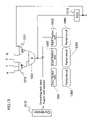
- FIG. 1 is a block diagram showing an essential exemplary structure of a computer system according to an embodiment of the present invention.
- FIG. 2 is a block diagram showing a hardware structure of a behavioral synthesis apparatus shown in FIG. 1 .
- FIG. 4 is a diagram showing an exemplary CDFG.
- FIGS. 5( a ) and ( b ) show two examples of results obtained after a scheduling process is performed on the CDFG shown in FIG. 4 , respectively.
- FIGS. 6( a ) and ( b ) show an exemplary circuit structure for executing a result of the scheduling process shown in FIGS. 5( a ) and 5 ( b ), respectively.
- FIG. 7 is a diagram showing an exemplary circuit having an input fixation unit inserted in the circuit shown in FIG. 6( b ).
- FIG. 8 is a diagram showing an exemplary circuit having an input fixation unit inserted when a subsequent computing unit is a multiplier.
- FIG. 9 is a diagram showing an example of an input fixation unit using AND gates.
- FIG. 10 is a diagram showing an exemplary circuit having an input fixation unit inserted when a subsequent computing unit is a bit OR circuit.
- FIG. 11 is a diagram showing an example of an input fixation unit using OR gates.
- FIG. 12 shows an example of a CDFG having three multiplication processes therein.
- FIG. 13 is a diagram showing an exemplary circuit for executing the CDFG shown in FIG. 12 .
- FIG. 14 is a block diagram showing an essential exemplary structure of a computer system according to another embodiment of the present invention.
- FIG. 15 is a block diagram showing a hardware structure of a behavioral synthesis apparatus shown in FIG. 14 .
- FIG. 16 is a flowchart showing a procedure of a behavioral synthesis process by the behavioral synthesis apparatus shown in FIG. 14 .
- FIG. 1 is a block diagram showing an essential exemplary structure of a computer system according to an embodiment of the present invention.
- a computer system 1 includes: a behavioral description storage unit for storing behavioral description 10 or an external input unit to which the behavior description 10 is externally input; a behavioral synthesis apparatus 20 for performing a behavioral synthesis process in order to automatically generate an RTL description 40 from the behavioral description 10 ; a database 30 for holding data required by the behavioral synthesis apparatus 20 for the behavioral synthesis process; and an RTL description storage unit for storing the RTL description 40 from the behavioral synthesis apparatus 20 or an external output unit capable of directly outputting the RTL description from the behavioral synthesis apparatus 20 to the outside.
- the behavioral synthesis apparatus 20 includes: control data flow graph (CDFG) generation section 21 ; scheduling section 22 ; allocation section 23 ; data path/controller generation section 24 ; and a computing unit input fixation section 25 .
- CDFG control data flow graph
- the behavioral synthesis process in order to automatically generate the RTL description 40 from the behavior description 10 by a computer, when a computing unit is shared by a plurality of computation processes, an input fixation unit is inserted by the unit input fixation section 25 between this computing unit described above and at least one its subsequent computing unit, which will be described later in detail as a characteristic structure of the present invention.
- the input fixation unit fixes input to the subsequent computing unit during cycles (the subsequent computing unit is inactive) other than a valid cycle at which a result to be computed at the subsequent computing unit is valid (the subsequent computing unit is active).
- the subsequent computing unit is inactive, even if an output of the target computing unit is changed, it is possible to suppress power consumption wasted by the subsequent computing unit since input to the subsequent computing unit is fixed by the input fixation unit and thus does not change.
- the behavior description 10 which only describes behaviors of a circuit but does not describe information regarding a structure of hardware, is input and a behavioral synthesis process is performed.
- the RTL description 40 is output as a result of the behavioral synthesis process.
- a CDFG which is generated by the behavioral synthesis apparatus 20 as an interim data during the behavioral synthesis process; a scheduling result; an allocation result; data path/controller structural information and the like each are stored in the database 30 and are made reference to as necessary.
- the behavioral synthesis apparatus 20 includes: an operation input unit 20 A (e.g., keyboard, mouse, screen input device) capable of issuing a variety of input orders; a display unit 20 B capable of displaying on a display screen a variety of images (e.g., initial screen, selection guidance screen and process result screen) according to the variety of input orders; a CPU 20 C (Central Processing Unit) as control section for controlling the entire behavioral synthesis apparatus 20 ; an RAM 20 D as a temporary storage section serving as a work memory when the CPU is initiated; and a ROM 20 E as a computer-readable recording medium (storage section) having a behavioral synthesis control program for operating the CPU 20 C and a variety of data and the like recorded thereon, which are used for the behavioral synthesis control program.
- an operation input unit 20 A e.g., keyboard, mouse, screen input device
- a display unit 20 B capable of displaying on a display screen a variety of images (e.g., initial screen, selection guidance screen and process result screen) according to the variety of input
- the CPU 20 C executes each of the functions of: CDFG generation section 21 for generating a control data flow graph (CDFG), which represents in a graph a flow of data as a branch and each process of computation and communication as a node, from a behavior description of a circuit, based on the behavioral synthesis control program and the variety of data used for this which have been read into the RAM 20 D from the ROM 20 E; scheduling section 22 for determining during which execution cycle a process at each node in the CDFG should be executed; an allocation section 23 for allocating a computation process to a circuit element and at the same time allocating data being currently processed to a register for storage; data path/controller generation section 24 for generating a data path and a controller for controlling the data path in accordance with each result processed by the scheduling section 22 and the allocation section 23 , and for creating a net list representing a connection relationship among the data path, the controller, computing units and registers; and a computing unit input fixation section 25 for inserting an input fixation unit between one of a plurality
- the ROM 20 E may be provided within the database 30 . However, in this case, the ROM 20 E is provided within in the behavioral synthesis apparatus 20 and structured with a computer-readable medium (storage section) (e.g., hard disk, optical disk, magnetic disk and IC memory).
- a computer-readable medium e.g., hard disk, optical disk, magnetic disk and IC memory.
- the behavioral synthesis control program and the variety of data used for the behavioral synthesis control program may be downloaded onto the ROM 20 E from a portable optical disk, magnetic disk, IC memory and the like. Alternatively, they may be downloaded onto the ROM 20 E from a hard disk of a computer. Still alternatively, they may be downloaded onto the ROM 20 E in a wired or wireless manner or via the Internet.
- FIG. 3 is a flowchart showing a procedure of the behavioral synthesis process by the behavioral synthesis apparatus 20 shown in FIG. 1 .
- a CDFG generation step in step S 1 the behavioral description 10 for a circuit, which only describes behaviors of the circuit but does not describe information regarding a structure of hardware, is input to the behavioral synthesis apparatus 20 , and then CDFG is automatically generated based on the input behavioral description 10 where a flow of data is represented as a branch and each process of computation and communication is represented as a node in a graph.
- This generated CDFG is registered in the database 36 as a set of branch/node information.
- This branch/node information includes a node number, a type of computation process, a node number of a branch for its connection and the like.
- One node in the CDFG is represented as one piece node of information, and the entire CDFG is represented as an array or list of the node information.
- a CDFG generation process is performed on a calculator since the number of nodes in the CDFG sometimes exceeds 10,000.
- the scheduling process and processes subsequent thereto are performed in a similar manner.
- the CDFG is numeric value data on the database 30 . However, for the sake of convenience for explanation, hereinafter, this numeric value data is represented in the graph shown in FIG. 4 .
- a scheduling step in step S 2 it is determined during which execution cycle each node (each process of computation and communication) in the CDFG should be executed.
- Information of the determined execution cycle is added to the branch/node information of each node on the database 30 .
- the method for determining the execution cycle is not particularly limited to any one method. However, any method may be applied for determining the execution cycle.
- the result which is obtained after the scheduling process is performed on the CDFG shown in FIG. 3 is shown, for example, in FIG. 5( b ) as an example in which a computing unit is shared by a plurality of computations, which has been described above.
- an allocation step in step S 3 a process for allocating a process at each node in the CDFG to a computing unit and a process for allocating data currently being processed to the register for storage are performed.
- Information of the allocated computing unit/register is added to the node information of each node on the database 30 .
- the method for allocating the computing unit/register is not particularly limited to any one method. However, any method may be applied for allocating the computing unit/register. It should be noted herein that there is a possibility that the same computation which is performed during a plurality of different cycles may be allocated to one computing unit. This allocation step may be performed prior to the scheduling step, depending on a method of behavioral synthesis process.
- a data path/controller generation step in step S 4 the data path (selector 312 ) and the controller 313 for controlling the data path (selector 312 ) are generated as shown in FIG. 6( b ), in accordance with the result of the scheduling step and the result of the allocation step.
- Information of the generated data path (selector 312 ) and the controller 313 is registered to the database 30 as a net list representing a connection relationship among computing units, registers, the data path and the controller.
- a computing unit input fixation step in step S 5 for the computing unit allocated with a plurality of computations in the allocation step, an input fixation unit is inserted between this target computing unit and each of its subsequent computing units at the output of target computing unit in the net list, which is obtained as a result of the data path generation process.
- the input fixation unit passes data to the subsequent computing unit at a cycle only when a process at the subsequent computing unit is valid (the subsequent computing unit is active) and otherwise fixes an input to the subsequent computing unit (the subsequent computing unit is inactive) a constant value.
- the scheduling process is performed as shown in FIG. 5( b ), and the nodes 101 and 103 are allocated with one multiplier 307 in the allocation step as shown in FIG. 6( b ), the data path (selector 312 ) is automatically generated.
- the result on the database 30 which is obtained by the process of the allocation section 23 , is made reference to, and then the one computing unit (multiplier) 307 , for a plurality of computation processes allocated with the plurality of computation processes by the allocation section 23 in the data flow graph, is searched. Accordingly, it is recognized that the multiplier 307 in FIG. 6( b ) is targeted for the computing unit input fixation step.
- an output from the multiplier 307 allocated with the plurality of computation processes is input to both the adder 308 and the subtracter 309 .
- Subsequent computing units (adder 308 and subtracter 309 ) for input from the output of the computing unit 307 are searched. Accordingly, input fixation units 314 and 315 are input between the multiplier 307 and the adder 308 and between the multiplier 307 and the subtracter 309 , respectively, as shown in FIG. 7 .
- a computing unit input fixation step in step S 5 includes a target computing unit searching step; a subsequent computing unit searching step; and an input fixation unit insertion step.
- the input fixation unit 314 inputs an output from the multiplier 307 to the adder 308 during cycle 1 when the adder 308 is active and otherwise fixes an input to the adder 308 to a constant value.
- the input to the adder 308 does not change, thereby preventing power from being wastefully consumed at the adder 308 .
- the input fixation unit 315 inputs an output from the multiplier 307 to the substracter 309 during cycle 2 when the substracter 309 is active and otherwise fixes an input to the substracter 309 to a constant value.
- the input to the substracter 309 does not change, thereby preventing power from being wastefully consumed at the substracter 309 .
- Cycle 1 and cycle 2 are not limited to one clock cycle. However, the state of cycle 1 and the state of cycle 2 may change every several clocks. Three or more computation processes may be allocated to one computing unit.
- the input fixation units 314 and 315 may be implemented, for example, with latch circuits.
- this latch circuit when an enable signal from the controller 313 , as a control signal, is in a “high” state (high level), an input from the multiplier 307 is output without change, and when an enable sign is in a “low” state (low level), a value of an output from latch circuit does not change even if any value is input from the multiplier 307 .
- control signals to the input fixation units 314 and 315 from the controller 313 are connected to enable signals from the latch circuits.
- the latch circuits can be used as the input fixation units 314 and 315 .
- a circuit including a plurality of AND gates 703 a as shown in FIG. 9 may be used as the input fixation unit 703 .
- the plurality of AND gates 703 a is controlled by a cycle signal from a controller 704 as a control signal.
- a logical product of a cycle signal from the controller 704 as a control signal and an input from the target computing unit 701 is output from the plurality of AND gates 703 a .
- this input fixation unit 703 when a cycle signal is in a “high state” (high level), an input from the target computing unit 701 is input to the subsequent multiplier 702 without change, and when a cycle signal is in a “low” state (low level), an output to the subsequent multiplier 702 is fixed by outputting “0” bits. Accordingly, when the multiplier 702 is inactive, a signal inside the subsequent multiplier 702 always has “0”, which does not cause switching nor consume power.
- a circuit size of the AND gate 703 a is smaller than that of a latch circuit.
- the multiplier 702 inactive, there is an advantage of not requiring an input fixation unit between the computing unit 705 and the subsequent multiplier 702 even if an output from a computing unit 705 which is connected to another input is changed.
- the reason for this is because the input fixation unit 703 always outputs “0” when the subsequent multiplier 702 is inactive.
- the input fixation unit 703 is provided at one of the outputs of the input fixation unit 703 to the subsequent multiplier 702 .
- FIG. 8 shows merely an example that the computing unit 702 is a multiplier.
- the computing unit 702 is a multiplier.
- a bit AND computing unit for example, as long as an output of a computing unit always has “0” when one of the inputs of the computing unit has “0”, then a similar effect can be obtained.
- the subsequent computing unit 702 is an adder or a subtracter
- an output of the subsequent computing unit 702 change even if one of the inputs of the subsequent computing unit 702 has “0”, thereby consuming power.
- a carry does not propagate, the number of switchings is reduced, and thus an effect of reducing power consumption is obtained.
- a computing unit 902 subsequent to a target computing unit 901 which is allocated in order to execute a plurality of computation processes in the allocation step (step S 3 )
- a circuit including a plurality of OR gates 903 a as shown in FIG. 11 may be used as the input fixation unit 903 .
- a logical sum of a cycle signal from a controller 904 and an output from the computing unit 901 is output.
- this input fixation unit 903 when a cycle signal is in a “high state” (high level), an output from the computing unit 901 is input, without change, to the bit OR computing unit 902 , and when a cycle signal is in a “low” state (low level), an input to a bit OR computing unit, which is the subsequent computing unit 902 , is fixed by outputting “1” bits. Accordingly, when the bit OR computing unit, which is the subsequent computing unit 902 , is inactive, a signal inside the bit OR computing unit, which is the subsequent multiplier 902 , always has “1”, which does not cause switching nor consume power.
- FIG. 10 shows merely an example that the subsequent computing unit 902 is a bit OR computing unit.
- the subsequent computing unit 902 is a bit OR computing unit.
- an input fixation unit is inserted between (i) a computing unit targeted for executing a plurality of computation processes by shifting a timing of the plurality of computation processes which are different from each other and (ii) a subsequent computing unit, thereby reducing power wastefully to be consumed at the subsequent computing unit and computing units subsequent to the subsequent computing units.
- FIG. 14 shows an essential exemplary structure of a computer system 1 A according to another embodiment in this case.
- FIG. 15 shows a hardware structure of a behavioral synthesis apparatus 201 of the computer system 1 A.
- FIG. 16 shows a procedure of a behavioral synthesis process by the behavioral synthesis apparatus 201 .
- an input fixation necessity determining section 25 A (input fixation necessity determining section S 5 A) for comparing a value of estimated power consumption when an input fixation unit is inserted between computing units and a value of estimated power consumption when no input fixation unit is inserted between the computing units and for initiating the computing unit fixation section 25 B at the next stage and inserting the input fixation unit between the computing units only when the former is smaller than the latter.
- the computing unit input fixation section 25 B includes: target computing unit searching section 251 B (target computing unit searching step S 51 B) for making reference to the result processed by the allocation section 23 and searching a target computing unit allocated by the allocation section 23 ; subsequent computing unit searching section 252 B (subsequent computing unit searching step S 52 B) for searching a subsequent computing unit, to which an output from the target computing unit is input; and input fixation unit insertion section 253 B (input fixation unit insertion section S 53 B) for inserting an input fixation unit between the target computing unit and the subsequent computing unit.
- target computing unit searching section 251 B target computing unit searching step S 51 B
- subsequent computing unit searching section 252 B subsequent computing unit searching step S 52 B
- input fixation unit insertion section 253 B input fixation unit insertion section S 53 B
- FIG. 12 shows an example of a CDFG having three multiplication processes therein.
- multiplication processes multipliers 1101 , 1102 and 1103
- these three multiplication processes are allocated so as to be executed by one multiplier.
- reference numeral 1104 represents a part of the CDFG, to which an output of the multiplier 1101 is transmitted
- reference numeral 1105 represents a part of the CDFG, to which an output of the multiplier 1102 is transmitted
- reference numeral 1106 represents a part of the CDFG, to which an output of the multiplier 1103 is transmitted.
- the partial CDFGs 1104 , 1105 and 1106 follow the CDFG downward from the multipliers 1101 , 1102 and 1103 , and the partial CDFGs 1104 , 1105 and 1106 are partial CDFG until a cycle is changed or before a shared computation process is reached.
- the reason for setting such partial CDFGs is because a result processed at a computing unit is not transmitted to its subsequent computing units since data is temporarily stored in a register when a cycle is changed, and a result of the shared computation process is not transmitted to its subsequent computing units by inserting an input fixation unit.
- FIG. 13 is a diagram showing a data path and controller for executing the partial CDFGs in FIG. 12 .
- an output from a multiplier 1207 is input to partial circuits 1204 , 1205 and 1206 for executing the partial CDFGs 1104 , 1105 and 1106 , respectively, via input fixation units 1201 , 1202 and 1203 .
- the input fixation units 1201 , 1202 and 1203 and selectors 1210 and 1211 for selecting an input to the multiplier 1207 are controlled by a control signal from a controller 1212 .
- An output terminal of an REG 1213 connected to an output from the multiplier 1207 is connected to the other input terminal of the selector 1211 .
- average power consumptions of the input fixation units 1201 , 1202 and 1203 are denoted as Pa 1 , Pa 2 and Pa 3 , respectively; average power consumptions of the partial circuits 1204 , 1205 and 1206 for executing the partial CDFGs are denoted as Pg 1 , Pg 2 and Pg 3 , respectively; and a ratio of the number of times each cycle 1 , 2 and 3 is executed is denoted as N 1 : N 2 : N 3 , respectively.
- Power consumed in a circuit correlates with the number of transistors included in the circuit.
- the number of transistors and a size of the circuit may be used as values of the power consumptions Pa 1 , Pa 2 , Pa 3 , Pg 1 , Pg 2 and Pg 3 .
- the ratio of N 1 , N 2 and N 3 of the number of the executions among cycles 1 , 2 and 3 is 1:1:1 in FIG. 12 .
- the ratios of this number of executions accordingly are used.
- a total power consumed at the partial circuit 1204 and the input fixation unit 1201 of the partial circuit 1204 in FIG. 13 is: N1 ⁇ (Pa1+Pg1) since an output from the multiplier 1207 changes only during cycle 1 .
- a total power consumed when the input fixation unit 1201 is not used is: (N1+N2+N3) ⁇ Pg1 since an output from the multiplier 1207 changes during cycles 1 , 2 and 3 .
- the input fixation necessity determining step S 5 A shown in FIG. 16 when N 1 ⁇ ( Pa 1 +Pg 1) ⁇ Pg 1 ⁇ ( N 1 +N 2 +N 3) is established, it is determined that an input fixation unit be inserted in the computing unit input fixation step S 5 B at the next stage.
- the input fixation necessity determining step S 5 A which is provided at a stage prior to the computing unit input fixation step S 5 B, a comparison is performed between a value of estimated power consumption when an input fixation unit is inserted between computing units and a value of estimated power consumption when no input fixation unit is inserted between the computing units, as described above.
- the computing unit fixation step S 5 B (computing unit input fixation section 25 B) is initiated and controlled so as to insert an input fixation unit, thereby preventing power consumption from unintendedly increasing due to the insertion of the input fixation unit.
- the determination formula shown above is merely an example.
- a term in view of static power consumption resulting from leak current of an input fixation unit may be added.
- a term in view of an increase of a size of an input fixation unit may be added.
- a behavioral synthesis apparatus 20 for generating a register transfer level (RTL) description from a behavior description an output of a computing unit is input to a plurality of its subsequent computing units, and in the case when a valid cycle in which a result computed at each subsequent computing unit is valid is different from each other, a computation unit input fixation section 25 is provided between the computing unit and at least one of its subsequent computing units in order to an input fixation unit for fixing an input of the subsequent computing units during cycles other than a cycle when a result computed at the subsequent computing unit is valid. Accordingly, the behavioral synthesis process can obtain an effect of the present invention that wasteful power consumption caused due to the sharing of one computing unit is prevented, thereby realizing low power consumption of hardware.
- RTL register transfer level
- a behavioral synthesis method using a computer system 1 including a behavioral synthesis apparatus 20 is used for automatically designing a digital circuit.
- a mask for forming each layer for a semiconductor apparatus is automatically designed based on the automatically designed digital circuit.
- Each mask is used for manufacturing an actual digital circuit.
- the actual digital circuit including a logical circuit manufactured in this manner can obtain an effect of the present invention that wasteful power consumption caused due to the sharing of one computing unit is prevented, thereby realizing low power consumption of hardware.
- a behavioral synthesis apparatus 20 or 201 for performing a computer-automated synthesis of a circuit description 10 of a register transfer level from a behavioral description describing a process operation of a circuit an output of a target computing unit is input to a plurality of subsequent computing units, and in the case when a valid cycle in which a result computed at each of the plurality of subsequent computing units is valid is different from each other, the behavioral synthesis apparatus only includes a computing unit fixation section 25 or 25 B for inserting an input fixation unit between the target computing unit and at least one of the plurality of subsequent computing units, the input fixation unit fixing an input value to “0”, “1” or the like to the at least one subsequent computing unit during cycles other than the valid cycle in which a result computed at the at least one subsequent computing unit is valid, thereby achieving the objective of the present invention of preventing an occurrence of wasteful power consumption caused due to the sharing of one computation unit in a behavioral synthesis
- the present invention inserts an input fixation unit on an output side of the shared computing unit.
- This input fixation unit passes data when a path belonging to the input fixation unit is active and outputs a fixed value (fixing an input) when the path belonging to the input fixation unit is inactive.
- a timing of not using a subsequent computing unit an input value to the subsequent computing unit from the shared computing unit is fixed to a constant value, thereby eliminating a wasteful switching to reduce power consumption.
- the input fixation unit is introduced at a predetermined position of a stage prior to the input fixation unit only when an effect of reducing power consumption is recognized owing to the insertion of the input fixation unit (only when an effect of reducing power consumption is detected).
- the present invention can be used for designing a system LSI based on C language.
- a behavioral synthesis apparatus of a computer system for performing a computer-automated synthesis of a circuit description of a register transfer level (RTL) from a behavioral description (design specification of a circuit) having a circuit behavior described therein in order to support designing and manufacturing of a digital circuit; a behavioral synthesis method using the behavioral synthesis apparatus; a method for manufacturing the digital circuit using the behavioral synthesis apparatus; a behavioral synthesis control program for performing the behavioral synthesis method; and a computer-readable recording medium having the behavioral synthesis control program recorded thereon, in the case of generating a circuit in which one computing unit is shared by a plurality of computation processes, by inserting an input fixation unit, for fixing input to its subsequent computing unit when the subsequent computing unit is inactive, between the computing unit and the subsequent computing unit, it is possible to suppress wasteful power consumption by the subsequent computing unit prevented, thereby realizing low power consumption of hardware.
- RTL register transfer level
Landscapes
- Engineering & Computer Science (AREA)
- Computer Hardware Design (AREA)
- Physics & Mathematics (AREA)
- Theoretical Computer Science (AREA)
- Evolutionary Computation (AREA)
- Geometry (AREA)
- General Engineering & Computer Science (AREA)
- General Physics & Mathematics (AREA)
- Design And Manufacture Of Integrated Circuits (AREA)
Abstract
Description
X=a×b+c
y=b×c−d
In
N1×(Pa1+Pg1)
since an output from the
(N1+N2+N3)×Pg1
since an output from the
N1×(Pa1+Pg1)<Pg1×(N1+N2+N3)
is established, it is determined that an input fixation unit be inserted in the computing unit input fixation step S5B at the next stage. In other words, in the input fixation necessity determining step S5A which is provided at a stage prior to the computing unit input fixation step S5B, a comparison is performed between a value of estimated power consumption when an input fixation unit is inserted between computing units and a value of estimated power consumption when no input fixation unit is inserted between the computing units, as described above. Only when the former value is smaller than the latter value, the computing unit fixation step S5B (computing unit
Claims (24)
Applications Claiming Priority (2)
| Application Number | Priority Date | Filing Date | Title |
|---|---|---|---|
| JP2006-031681 | 2006-02-08 | ||
| JP2006031681A JP4396987B2 (en) | 2006-02-08 | 2006-02-08 | Behavioral synthesis apparatus and behavioral synthesis method, digital circuit manufacturing method, behavioral synthesis control program, and readable recording medium |
Publications (2)
| Publication Number | Publication Date |
|---|---|
| US20070214447A1 US20070214447A1 (en) | 2007-09-13 |
| US7725843B2 true US7725843B2 (en) | 2010-05-25 |
Family
ID=38480362
Family Applications (1)
| Application Number | Title | Priority Date | Filing Date |
|---|---|---|---|
| US11/703,140 Expired - Fee Related US7725843B2 (en) | 2006-02-08 | 2007-02-07 | Behavioral synthesis apparatus, behavioral synthesis method, method for manufacturing digital circuit, behavioral synthesis control program and computer-readable recording medium |
Country Status (2)
| Country | Link |
|---|---|
| US (1) | US7725843B2 (en) |
| JP (1) | JP4396987B2 (en) |
Cited By (1)
| Publication number | Priority date | Publication date | Assignee | Title |
|---|---|---|---|---|
| US20090326901A1 (en) * | 2008-06-25 | 2009-12-31 | Kabushiki Kaisha Toshiba | Apparatus and method for estimating change amount in register transfer level structure and computer-readable recording medium |
Families Citing this family (6)
| Publication number | Priority date | Publication date | Assignee | Title |
|---|---|---|---|---|
| JP5023652B2 (en) * | 2006-10-17 | 2012-09-12 | 日本電気株式会社 | Circuit generation system, circuit generation method, and circuit generation program |
| JP4955484B2 (en) * | 2007-08-24 | 2012-06-20 | ルネサスエレクトロニクス株式会社 | Circuit design apparatus, circuit design method, and circuit design program |
| US8136063B2 (en) * | 2008-11-14 | 2012-03-13 | Synopsys, Inc. | Unfolding algorithm in multirate system folding |
| JP2010205084A (en) * | 2009-03-04 | 2010-09-16 | Renesas Electronics Corp | Operation synthesis system, operation synthesis method and operation synthesis program |
| JP2011059895A (en) * | 2009-09-08 | 2011-03-24 | Toshiba Corp | High-level synthesis apparatus |
| US10192014B2 (en) | 2015-08-27 | 2019-01-29 | Mitsubishi Electric Corporation | Circuit design support apparatus and computer readable medium |
Citations (7)
| Publication number | Priority date | Publication date | Assignee | Title |
|---|---|---|---|---|
| JPH06106476A (en) | 1992-09-25 | 1994-04-19 | Toyoda Mach Works Ltd | Contact detecting device |
| US6493863B1 (en) * | 1999-11-15 | 2002-12-10 | Matsushita Electric Industrial Co., Ltd. | Method of designing semiconductor integrated circuit |
| JP2002366596A (en) | 2001-06-11 | 2002-12-20 | Sharp Corp | Device, method for high-order synthesis, method of manufacturing logic circuit by high-order synthesizing method and recording medium |
| JP2003067433A (en) | 2001-08-24 | 2003-03-07 | Nec Microsystems Ltd | Redundancy operation detecting device, its detecting method and method for inserting operation stoppage circuit |
| US6557157B1 (en) * | 1997-04-10 | 2003-04-29 | Boethel Andreas Frank | Method for designing complex digital and integrated circuits as well as a circuit structure |
| JP2003150657A (en) | 2001-11-15 | 2003-05-23 | Matsushita Electric Ind Co Ltd | High order synthesis method and high order synthesizer |
| US20070057714A1 (en) * | 2005-09-15 | 2007-03-15 | Josef Holzle | Method and device for generating an output signal having a predetermined phase shift with respect to an input signal |
-
2006
- 2006-02-08 JP JP2006031681A patent/JP4396987B2/en not_active Expired - Fee Related
-
2007
- 2007-02-07 US US11/703,140 patent/US7725843B2/en not_active Expired - Fee Related
Patent Citations (7)
| Publication number | Priority date | Publication date | Assignee | Title |
|---|---|---|---|---|
| JPH06106476A (en) | 1992-09-25 | 1994-04-19 | Toyoda Mach Works Ltd | Contact detecting device |
| US6557157B1 (en) * | 1997-04-10 | 2003-04-29 | Boethel Andreas Frank | Method for designing complex digital and integrated circuits as well as a circuit structure |
| US6493863B1 (en) * | 1999-11-15 | 2002-12-10 | Matsushita Electric Industrial Co., Ltd. | Method of designing semiconductor integrated circuit |
| JP2002366596A (en) | 2001-06-11 | 2002-12-20 | Sharp Corp | Device, method for high-order synthesis, method of manufacturing logic circuit by high-order synthesizing method and recording medium |
| JP2003067433A (en) | 2001-08-24 | 2003-03-07 | Nec Microsystems Ltd | Redundancy operation detecting device, its detecting method and method for inserting operation stoppage circuit |
| JP2003150657A (en) | 2001-11-15 | 2003-05-23 | Matsushita Electric Ind Co Ltd | High order synthesis method and high order synthesizer |
| US20070057714A1 (en) * | 2005-09-15 | 2007-03-15 | Josef Holzle | Method and device for generating an output signal having a predetermined phase shift with respect to an input signal |
Cited By (1)
| Publication number | Priority date | Publication date | Assignee | Title |
|---|---|---|---|---|
| US20090326901A1 (en) * | 2008-06-25 | 2009-12-31 | Kabushiki Kaisha Toshiba | Apparatus and method for estimating change amount in register transfer level structure and computer-readable recording medium |
Also Published As
| Publication number | Publication date |
|---|---|
| JP4396987B2 (en) | 2010-01-13 |
| JP2007213265A (en) | 2007-08-23 |
| US20070214447A1 (en) | 2007-09-13 |
Similar Documents
| Publication | Publication Date | Title |
|---|---|---|
| US7725843B2 (en) | Behavioral synthesis apparatus, behavioral synthesis method, method for manufacturing digital circuit, behavioral synthesis control program and computer-readable recording medium | |
| US6678644B1 (en) | Integrated circuit models having associated timing exception information therewith for use with electronic design automation | |
| US6195786B1 (en) | Constrained register sharing technique for low power VLSI design | |
| US7318213B2 (en) | Apparatus, method and program for behavioral synthesis including loop processing | |
| US6438731B1 (en) | Integrated circuit models having associated timing exception information therewith for use in circuit design optimizations | |
| US10901490B2 (en) | Operating point controller for circuit regions | |
| US8671371B1 (en) | Systems and methods for configuration of control logic in parallel pipelined hardware | |
| US8291364B2 (en) | Automated digital circuit design tool that reduces or eliminates adverse timing constraints do to an inherent clock signal skew, and applications thereof | |
| US8701069B1 (en) | Systems and methods for optimizing allocation of hardware resources to control logic in parallel pipelined hardware | |
| Gluzer et al. | Probability-driven multibit flip-flop integration with clock gating | |
| US7958476B1 (en) | Method for multi-cycle path and false path clock gating | |
| US9058451B2 (en) | Automatic synthesis of complex clock systems | |
| JP5630870B2 (en) | Semiconductor integrated circuit layout method and program | |
| Shin et al. | HLS-dv: A high-level synthesis framework for dual-Vdd architectures | |
| US6505340B2 (en) | Circuit synthesis method | |
| Kojima et al. | Glitch-aware variable pipeline optimization for CGRAs | |
| Chang et al. | An optimal clock period selection method based on slack minimization criteria | |
| Chen et al. | Power-manageable scheduling technique for control dominated high-level synthesis | |
| Kondratyev et al. | Exploiting area/delay tradeoffs in high-level synthesis | |
| US8176451B2 (en) | Behavioral synthesis apparatus, behavioral synthesis method, and computer readable recording medium | |
| JP2010277436A (en) | Memory structure determination support device, memory structure determination program and recording medium | |
| Wang et al. | Power-gating-aware scheduling with effective hardware resources optimization | |
| Kamal et al. | Design of NBTI-resilient extensible processors | |
| Terada et al. | A floorplan-driven high-level synthesis algorithm with operation chainings using chaining enumeration | |
| Wu et al. | Simultaneous functional units and register allocation based power management for high-level synthesis of data-intensive applications |
Legal Events
| Date | Code | Title | Description |
|---|---|---|---|
| AS | Assignment |
Owner name: SHARP KABUSHIKI KAISHA,JAPAN Free format text: ASSIGNMENT OF ASSIGNORS INTEREST;ASSIGNOR:OKADA, KAZUHISA;REEL/FRAME:019370/0477 Effective date: 20070210 Owner name: SHARP KABUSHIKI KAISHA, JAPAN Free format text: ASSIGNMENT OF ASSIGNORS INTEREST;ASSIGNOR:OKADA, KAZUHISA;REEL/FRAME:019370/0477 Effective date: 20070210 |
|
| FPAY | Fee payment |
Year of fee payment: 4 |
|
| FEPP | Fee payment procedure |
Free format text: PAYOR NUMBER ASSIGNED (ORIGINAL EVENT CODE: ASPN); ENTITY STATUS OF PATENT OWNER: LARGE ENTITY |
|
| FEPP | Fee payment procedure |
Free format text: MAINTENANCE FEE REMINDER MAILED (ORIGINAL EVENT CODE: REM.) |
|
| LAPS | Lapse for failure to pay maintenance fees |
Free format text: PATENT EXPIRED FOR FAILURE TO PAY MAINTENANCE FEES (ORIGINAL EVENT CODE: EXP.) |
|
| STCH | Information on status: patent discontinuation |
Free format text: PATENT EXPIRED DUE TO NONPAYMENT OF MAINTENANCE FEES UNDER 37 CFR 1.362 |
|
| FP | Lapsed due to failure to pay maintenance fee |
Effective date: 20180525 |