US7690450B2 - System for operating a hydraulically actuated device - Google Patents
System for operating a hydraulically actuated device Download PDFInfo
- Publication number
- US7690450B2 US7690450B2 US11/713,227 US71322707A US7690450B2 US 7690450 B2 US7690450 B2 US 7690450B2 US 71322707 A US71322707 A US 71322707A US 7690450 B2 US7690450 B2 US 7690450B2
- Authority
- US
- United States
- Prior art keywords
- accumulator
- hydraulically actuated
- actuated device
- vehicle
- requested
- Prior art date
- Legal status (The legal status is an assumption and is not a legal conclusion. Google has not performed a legal analysis and makes no representation as to the accuracy of the status listed.)
- Active, expires
Links
Images


Classifications
-
- B—PERFORMING OPERATIONS; TRANSPORTING
- B60—VEHICLES IN GENERAL
- B60W—CONJOINT CONTROL OF VEHICLE SUB-UNITS OF DIFFERENT TYPE OR DIFFERENT FUNCTION; CONTROL SYSTEMS SPECIALLY ADAPTED FOR HYBRID VEHICLES; ROAD VEHICLE DRIVE CONTROL SYSTEMS FOR PURPOSES NOT RELATED TO THE CONTROL OF A PARTICULAR SUB-UNIT
- B60W10/00—Conjoint control of vehicle sub-units of different type or different function
- B60W10/30—Conjoint control of vehicle sub-units of different type or different function including control of auxiliary equipment, e.g. air-conditioning compressors or oil pumps
-
- B—PERFORMING OPERATIONS; TRANSPORTING
- B60—VEHICLES IN GENERAL
- B60K—ARRANGEMENT OR MOUNTING OF PROPULSION UNITS OR OF TRANSMISSIONS IN VEHICLES; ARRANGEMENT OR MOUNTING OF PLURAL DIVERSE PRIME-MOVERS IN VEHICLES; AUXILIARY DRIVES FOR VEHICLES; INSTRUMENTATION OR DASHBOARDS FOR VEHICLES; ARRANGEMENTS IN CONNECTION WITH COOLING, AIR INTAKE, GAS EXHAUST OR FUEL SUPPLY OF PROPULSION UNITS IN VEHICLES
- B60K25/00—Auxiliary drives
-
- B—PERFORMING OPERATIONS; TRANSPORTING
- B60—VEHICLES IN GENERAL
- B60K—ARRANGEMENT OR MOUNTING OF PROPULSION UNITS OR OF TRANSMISSIONS IN VEHICLES; ARRANGEMENT OR MOUNTING OF PLURAL DIVERSE PRIME-MOVERS IN VEHICLES; AUXILIARY DRIVES FOR VEHICLES; INSTRUMENTATION OR DASHBOARDS FOR VEHICLES; ARRANGEMENTS IN CONNECTION WITH COOLING, AIR INTAKE, GAS EXHAUST OR FUEL SUPPLY OF PROPULSION UNITS IN VEHICLES
- B60K6/00—Arrangement or mounting of plural diverse prime-movers for mutual or common propulsion, e.g. hybrid propulsion systems comprising electric motors and internal combustion engines ; Control systems therefor, i.e. systems controlling two or more prime movers, or controlling one of these prime movers and any of the transmission, drive or drive units Informative references: mechanical gearings with secondary electric drive F16H3/72; arrangements for handling mechanical energy structurally associated with the dynamo-electric machine H02K7/00; machines comprising structurally interrelated motor and generator parts H02K51/00; dynamo-electric machines not otherwise provided for in H02K see H02K99/00
- B60K6/08—Prime-movers comprising combustion engines and mechanical or fluid energy storing means
- B60K6/12—Prime-movers comprising combustion engines and mechanical or fluid energy storing means by means of a chargeable fluidic accumulator
-
- E—FIXED CONSTRUCTIONS
- E02—HYDRAULIC ENGINEERING; FOUNDATIONS; SOIL SHIFTING
- E02F—DREDGING; SOIL-SHIFTING
- E02F9/00—Component parts of dredgers or soil-shifting machines, not restricted to one of the kinds covered by groups E02F3/00 - E02F7/00
- E02F9/20—Drives; Control devices
- E02F9/22—Hydraulic or pneumatic drives
- E02F9/2217—Hydraulic or pneumatic drives with energy recovery arrangements, e.g. using accumulators, flywheels
-
- E—FIXED CONSTRUCTIONS
- E02—HYDRAULIC ENGINEERING; FOUNDATIONS; SOIL SHIFTING
- E02F—DREDGING; SOIL-SHIFTING
- E02F9/00—Component parts of dredgers or soil-shifting machines, not restricted to one of the kinds covered by groups E02F3/00 - E02F7/00
- E02F9/20—Drives; Control devices
- E02F9/22—Hydraulic or pneumatic drives
- E02F9/2221—Control of flow rate; Load sensing arrangements
- E02F9/2232—Control of flow rate; Load sensing arrangements using one or more variable displacement pumps
- E02F9/2235—Control of flow rate; Load sensing arrangements using one or more variable displacement pumps including an electronic controller
-
- E—FIXED CONSTRUCTIONS
- E02—HYDRAULIC ENGINEERING; FOUNDATIONS; SOIL SHIFTING
- E02F—DREDGING; SOIL-SHIFTING
- E02F9/00—Component parts of dredgers or soil-shifting machines, not restricted to one of the kinds covered by groups E02F3/00 - E02F7/00
- E02F9/20—Drives; Control devices
- E02F9/22—Hydraulic or pneumatic drives
- E02F9/2278—Hydraulic circuits
- E02F9/2296—Systems with a variable displacement pump
-
- F—MECHANICAL ENGINEERING; LIGHTING; HEATING; WEAPONS; BLASTING
- F16—ENGINEERING ELEMENTS AND UNITS; GENERAL MEASURES FOR PRODUCING AND MAINTAINING EFFECTIVE FUNCTIONING OF MACHINES OR INSTALLATIONS; THERMAL INSULATION IN GENERAL
- F16H—GEARING
- F16H61/00—Control functions within control units of change-speed- or reversing-gearings for conveying rotary motion ; Control of exclusively fluid gearing, friction gearing, gearings with endless flexible members or other particular types of gearing
- F16H61/38—Control of exclusively fluid gearing
- F16H61/40—Control of exclusively fluid gearing hydrostatic
- F16H61/4069—Valves related to the control of neutral, e.g. shut off valves
-
- F—MECHANICAL ENGINEERING; LIGHTING; HEATING; WEAPONS; BLASTING
- F16—ENGINEERING ELEMENTS AND UNITS; GENERAL MEASURES FOR PRODUCING AND MAINTAINING EFFECTIVE FUNCTIONING OF MACHINES OR INSTALLATIONS; THERMAL INSULATION IN GENERAL
- F16H—GEARING
- F16H61/00—Control functions within control units of change-speed- or reversing-gearings for conveying rotary motion ; Control of exclusively fluid gearing, friction gearing, gearings with endless flexible members or other particular types of gearing
- F16H61/38—Control of exclusively fluid gearing
- F16H61/40—Control of exclusively fluid gearing hydrostatic
- F16H61/4078—Fluid exchange between hydrostatic circuits and external sources or consumers
- F16H61/4096—Fluid exchange between hydrostatic circuits and external sources or consumers with pressure accumulators
-
- F—MECHANICAL ENGINEERING; LIGHTING; HEATING; WEAPONS; BLASTING
- F16—ENGINEERING ELEMENTS AND UNITS; GENERAL MEASURES FOR PRODUCING AND MAINTAINING EFFECTIVE FUNCTIONING OF MACHINES OR INSTALLATIONS; THERMAL INSULATION IN GENERAL
- F16H—GEARING
- F16H61/00—Control functions within control units of change-speed- or reversing-gearings for conveying rotary motion ; Control of exclusively fluid gearing, friction gearing, gearings with endless flexible members or other particular types of gearing
- F16H61/38—Control of exclusively fluid gearing
- F16H61/40—Control of exclusively fluid gearing hydrostatic
- F16H61/4148—Open loop circuits
-
- B—PERFORMING OPERATIONS; TRANSPORTING
- B60—VEHICLES IN GENERAL
- B60W—CONJOINT CONTROL OF VEHICLE SUB-UNITS OF DIFFERENT TYPE OR DIFFERENT FUNCTION; CONTROL SYSTEMS SPECIALLY ADAPTED FOR HYBRID VEHICLES; ROAD VEHICLE DRIVE CONTROL SYSTEMS FOR PURPOSES NOT RELATED TO THE CONTROL OF A PARTICULAR SUB-UNIT
- B60W20/00—Control systems specially adapted for hybrid vehicles
-
- B—PERFORMING OPERATIONS; TRANSPORTING
- B60—VEHICLES IN GENERAL
- B60W—CONJOINT CONTROL OF VEHICLE SUB-UNITS OF DIFFERENT TYPE OR DIFFERENT FUNCTION; CONTROL SYSTEMS SPECIALLY ADAPTED FOR HYBRID VEHICLES; ROAD VEHICLE DRIVE CONTROL SYSTEMS FOR PURPOSES NOT RELATED TO THE CONTROL OF A PARTICULAR SUB-UNIT
- B60W2300/00—Indexing codes relating to the type of vehicle
- B60W2300/12—Trucks; Load vehicles
-
- F—MECHANICAL ENGINEERING; LIGHTING; HEATING; WEAPONS; BLASTING
- F16—ENGINEERING ELEMENTS AND UNITS; GENERAL MEASURES FOR PRODUCING AND MAINTAINING EFFECTIVE FUNCTIONING OF MACHINES OR INSTALLATIONS; THERMAL INSULATION IN GENERAL
- F16H—GEARING
- F16H59/00—Control inputs to control units of change-speed-, or reversing-gearings for conveying rotary motion
- F16H59/36—Inputs being a function of speed
- F16H59/44—Inputs being a function of speed dependent on machine speed of the machine, e.g. the vehicle
- F16H2059/446—Detecting vehicle stop, i.e. the vehicle is at stand still, e.g. for engaging parking lock
-
- Y—GENERAL TAGGING OF NEW TECHNOLOGICAL DEVELOPMENTS; GENERAL TAGGING OF CROSS-SECTIONAL TECHNOLOGIES SPANNING OVER SEVERAL SECTIONS OF THE IPC; TECHNICAL SUBJECTS COVERED BY FORMER USPC CROSS-REFERENCE ART COLLECTIONS [XRACs] AND DIGESTS
- Y02—TECHNOLOGIES OR APPLICATIONS FOR MITIGATION OR ADAPTATION AGAINST CLIMATE CHANGE
- Y02T—CLIMATE CHANGE MITIGATION TECHNOLOGIES RELATED TO TRANSPORTATION
- Y02T10/00—Road transport of goods or passengers
- Y02T10/60—Other road transportation technologies with climate change mitigation effect
- Y02T10/62—Hybrid vehicles
Definitions
- This invention relates in general to systems for operating hydraulically actuated devices.
- this invention relates to an improved system for operating a hydraulically actuated device that is provided on a movable vehicle.
- Trucks and other types of movable vehicles are often equipped with one or more hydraulically actuated devices for performing a variety of functions, such as snow plowing, earth moving, and the like.
- a source of pressurized fluid is typically provided on the vehicle to operate the hydraulically actuated device in a desired manner.
- the engine of the vehicle allows the vehicle to be moved as desired, while the source of pressurized fluid allows the hydraulically actuated device to be operated to perform the desired function.
- the source of pressurized fluid allows the hydraulically actuated device to be operated independently of whether the vehicle is moving.
- the source of pressurized fluid is an electrically operated hydraulic pump that is electrically connected to the electrical system of the vehicle. Although such electrically operated hydraulic pumps are effective, they have been found to be relatively difficult to maintain and, in some situations, may require customization of the electrical system of the vehicle in order to safely allow the necessary amount of electrical power to operate the hydraulic pump to be drawn.
- the source of pressurized fluid is a mechanically operated clutch pump that is connected to the engine of the vehicle by means of an aftermarket serpentine belt. Although such mechanically operated clutch pumps are also effective, they have been found to be relatively difficult to maintain, involve the use of customized installation hardware, and can place an unduly large load on the engine of the vehicle.
- the source of pressurized fluid is a mechanically operated hydraulic pump that is driven by a power take-off unit connected to the transmission of the vehicle.
- Such mechanically operated power take-off unit/hydraulic pump assemblies avoid many of the drawbacks mentioned above.
- the use of these power take-off unit/hydraulic pump assemblies in vehicles having automatic transmissions is often undesirable because the amount of power that is available for use from the power take-off unit is limited or non-existent when the automatic transmission is in a moving gear ratio (i.e., forward or reverse), but the vehicle itself is stationary.
- This invention relates to an improved system for operating a hydraulically actuated device that is provided on a vehicle.
- the system includes a power take-off unit that is adapted to be driven by a transmission of a vehicle and a hydraulic pump that is driven by the power take-off unit.
- the system also includes an accumulator and a hydraulically actuated device.
- the system includes a controller that causes the hydraulic pump to supply pressurized fluid to the hydraulically actuated device when the vehicle is moving. When the vehicle is not moving, however, the controller causes the accumulator to supply pressurized fluid to the hydraulically actuated device.
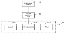
- FIG. 1 is a schematic block diagram of a vehicular drive train assembly and a hydraulic system in accordance with this invention that cooperates with the vehicular drive train assembly.
- FIG. 2 is a more detailed block diagram of the structure of the hydraulic system illustrated in FIG. 1 .
- FIG. 3 is a flowchart that shows the operation of the hydraulic system illustrated in FIGS. 1 and 2 .
- FIG. 1 a schematic block diagram of a drive train assembly, indicated generally at 10 , for a truck or any other type of vehicle.
- the illustrated vehicle drive train assembly 10 is, in large measure, conventional in the art and is intended merely to illustrate one environment in which this invention may be used.
- the scope of this invention is not intended to be limited for use with the specific structure for the vehicle drive train assembly 10 illustrated in FIG. 1 or with vehicle drive train assemblies in general.
- this invention may be used in any desired environment for the purposes described below.
- the illustrated vehicular drive train system 10 includes an engine 11 , a transmission 12 , and an axle assembly 13 .
- the engine 11 is conventional in the art and may, for example, be embodied as an internal combustion or diesel engine. However, the engine 11 may be embodied as any desired structure that functions as a source of mechanical rotational power.
- the transmission 12 is also conventional in the art and may, for example, be embodied as an automatic, automated manual, or manual transmission. However, the transmission 12 may be embodied as any desired structure that functions to transfer the mechanical rotational power from the engine 11 to the axle assembly 13 at a variety of moving gear ratios (i.e., forward and reverse), thereby allowing changes of torque and speed, and non-moving gear ratios (i.e., park or neutral).
- the axle assembly 13 is also conventional in the art and may, for example, be embodied as a differential mechanism. However, the axle assembly 13 may be embodied as any desired structure that transmits the mechanical rotational power from the transmission 12 to the wheels of the vehicle.
- FIG. 1 also illustrates a power take-off unit 20 that is connected to the transmission 12 of the vehicular drive train assembly 10 .
- the power take-off unit 20 is conventional in the art and may, for example, include a housing (not shown) that rotatably supports an input gear (which is rotatably driven by the transmission 12 ), an output shaft, and a set of meshing intermediate gears.
- the meshing intermediate gears are connected in a gear train between input gear and the output shaft so as to provide a rotatable driving connection therebetween.
- the set of gears permits one or more speed reduction gear ratios to be provided between the input gear and the output shaft.
- the power take-off unit 20 may include a clutch assembly for selectively disconnecting the output shaft from the input gear.
- the power take-off unit 20 may be embodied as any desired structure that is responsive to operation of the transmission 12 for causing rotation of the output shaft.
- FIG. 1 further illustrates a hydraulic system 30 that cooperates with the power take-off unit 20 and the vehicular drive train system 10 in accordance with this invention.
- the structure of the hydraulic system 30 is illustrated in detail in FIG. 2 .
- the hydraulic system 30 includes a hydraulic pump 31 that is connected to the power take-off unit 20 and is mechanically driven by the output shaft thereof.
- the hydraulic pump 31 is also conventional in the art and may, for example, include a housing (not shown) that supports a pumping mechanism.
- the housing of the hydraulic pump 31 may be supported directly on the housing of the power take-off unit 20 such that the output shaft of the power take-off unit 20 extends therein into cooperation with the pumping mechanism.
- the hydraulic pump 31 may be embodied as any desired structure that is responsive to rotation of the output shaft of the power take-off unit 20 for drawing hydraulic fluid from a reservoir 32 into an inlet port thereof and for generating a flow of hydraulic fluid through an output port thereof.
- the output port of the hydraulic pump 31 is connected through a pump unloading valve 33 to the reservoir 32 .
- the pump unloading valve 33 is conventional in the art and is operable in either an opened condition, wherein fluid communication from the hydraulic pump 31 to the reservoir 32 is permitted, and a closed condition, wherein fluid communication from the hydraulic pump 31 to the reservoir 32 is prevented.
- the pump unloading valve 33 is a solenoid-operated fluid valve.
- the pump unloading valve 33 may be embodied as any desired fluid valve structure.
- the output port of the hydraulic pump 31 is also connected through a pump actuating valve 34 to a hydraulically actuated device 35 .
- the pump actuating valve 34 is also conventional in the art and is operable in either an opened condition, wherein fluid communication from the hydraulic pump 31 to the hydraulically actuated device 35 is permitted, and a closed condition, wherein fluid communication from the hydraulic pump 31 to the hydraulically actuated device 35 is prevented.
- the pump actuating valve 34 is a solenoid-operated fluid valve.
- the pump actuating valve 34 may be embodied as any desired fluid valve structure.
- the illustrated hydraulically actuated device 35 is intended to be representative of any mechanism or group of mechanisms that is responsive to the flow of hydraulic fluid from the output port of the hydraulic pump 31 for performing a function.
- the hydraulically actuated device 35 may be a device that is responsive to the flow of hydraulic fluid from the hydraulic pump 31 for performing snow plowing, earth moving, or other functions.
- the hydraulically actuated device 35 can be a double-acting mechanism such as, for example, a hydraulically actuated linear actuator having a piston that can reciprocate in two directions relative to a cylinder.
- a plurality of valves may be provided for actuating the hydraulically actuated device 35 , as is well known in the art.
- the power take-off unit 20 drives the hydraulic pump 31 to generate a flow of pressurized hydraulic fluid to the hydraulically actuated device 35 , causing same to be operated.
- the hydraulic fluid then flows from the hydraulically actuated device 35 back to the reservoir 32 , where it can be drawn into the input port of the hydraulic pump 31 as described above to complete a hydraulic circuit.
- the output port of the hydraulic pump 31 is further connected through an accumulator charge valve 36 to a hydraulic accumulator 37 .
- the accumulator charge valve 36 is conventional in the art and is operable in either an opened condition, wherein fluid communication from the hydraulic pump 31 to the accumulator 37 is permitted, and a closed condition, wherein fluid communication from the hydraulic pump 31 to the accumulator 37 is prevented.
- the accumulator charge valve 36 is a solenoid-operated fluid valve.
- the accumulator charge valve 36 may be embodied as any desired fluid valve structure.
- the accumulator 37 is conventional in the art and is adapted to store fluid under pressure.
- the accumulator 37 may be a vessel in which a quantity of essentially non-compressible hydraulic fluid is held under pressure by an external source, such as a spring or a compressed gas.
- the accumulator 37 may be embodied as any desired structure for storing a quantity of pressurized hydraulic fluid from the hydraulic pump 31 . The purpose for the accumulator 37 will be explained in detail below.
- the accumulator 37 is connected through an accumulator discharge valve 38 to the hydraulically actuated device 35 .
- the accumulator discharge valve 38 is conventional in the art and is operable in either an opened condition, wherein fluid communication from the accumulator 37 to the hydraulically actuated device 35 is permitted, and a closed condition, wherein fluid communication from the accumulator 37 to the hydraulically actuated device 35 is prevented.
- the accumulator discharge valve 38 is a solenoid-operated fluid valve.
- the accumulator discharge valve 38 may be embodied as any desired fluid valve structure.
- the pump unloading valve 33 , the pump actuating valve 34 , the accumulator charge valve 36 , and the accumulator discharge valve 38 are each preferably embodied as solenoid-operated fluid valves. If desired, the pump unloading valve 33 , the pump actuating valve 34 , the accumulator charge valve 36 , and the accumulator discharge valve 38 can all be provided within a single valve manifold block (not shown), the structure of which is conventional in the art.
- the hydraulic system 30 includes a controller 39 that controls the operations of the pump unloading valve 33 , the pump actuating valve 34 , the accumulator charge valve 36 , and the accumulator discharge valve 38 .
- the controller 39 is conventional in the art and may, for example, be embodied as any electronic control circuit, such as a microprocessor or a programmable controller.
- the controller 39 controls the operations of the pump unloading valve 33 , the pump actuating valve 34 , the accumulator charge valve 36 , and the accumulator discharge valve 38 to operate the hydraulic system 30 in accordance with this invention.
- FIG. 3 is a flowchart of a method, indicated generally at 40 , by which the controller 39 controls the operation of the hydraulic system 30 illustrated in FIGS. 1 and 2 in accordance with this invention.
- a determination is whether the transmission 12 of the drive train assembly 10 is in a non-moving gear ratio (i.e., park or neutral). This determination can be made in any conventional manner, such as by providing the transmission 12 with a conventional gear ratio sensor (not shown) that generates a signal that is representative of the gear ratio of the transmission 12 .
- the method 40 branches to an instruction 42 , wherein the controller 39 is actuated to charge the accumulator 37 with pressurized fluid from the hydraulic pump 31 .
- the controller 39 is actuated to charge the accumulator 37 with pressurized fluid from the hydraulic pump 31 .
- This can be accomplished by causing the controller 39 to generate appropriate signals to close the pump unloading valve 33 , close the pump actuating valve 34 , open the accumulator charge valve 36 , and close the accumulator discharge valve 38 .
- the engagement of the power take-off unit 20 with the transmission 12 will cause the hydraulic pump 31 to be operated.
- pressurized hydraulic fluid flows from the hydraulic pump 31 through the accumulator charge valve 36 into the accumulator 37 .
- the method 40 then enters a decision point 43 , wherein it is determined whether the pressure of the hydraulic fluid in the accumulator 37 has been raised to a predetermined desired level. This determination can be made in any conventional manner, such as by providing the accumulator 37 with a conventional pressure sensor (not shown) that generates a signal that is representative of the pressure of the hydraulic fluid within the accumulator 37 . The controller 39 can compare this pressure sensor signal with a predetermined threshold signal to make this determination. If the pressure of the hydraulic fluid in the accumulator 37 has not reached the predetermined desired level, the method 40 branches from the decision point 43 back to the instruction 42 , wherein the accumulator 37 continues to receive pressurized fluid from the hydraulic pump 31 .
- the method 40 branches from the decision point 43 to a decision point 44 , wherein it is determined whether the power take-off unit 20 is being operated by the transmission 12 of the vehicular drive train system 10 .
- a decision point 44 it is increasing common for trucks and other relatively heavy duty vehicles to be provided with automatic transmissions. In these instances, when the automatic transmission is in a moving gear ratio (i.e., forward or reverse), but the vehicle itself is stationary, the automatic transmission does not operate the power take-off unit 20 .
- This determination can be made in any conventional manner, such as by providing the vehicle with a conventional shaft sensor (not shown) that generates a signal that is representative of the rotational of a shaft contained within the power take-off unit 20 , such as the input shaft or the output shaft.
- the controller 39 can compare this shaft sensor signal with a predetermined threshold signal to make this determination. Referring back to the initial decision point 41 mentioned above, if it is determined that the transmission 12 is not in a non-moving gear ratio (i.e., is in forward or reverse), then the method 40 branches directly to the decision point 44 .
- the method 40 branches from the decision point 44 to a decision point 45 , wherein it is determined whether it is desired to operate the hydraulically actuated device 35 .
- This determination can be made in any conventional manner, such as by providing an electrical switch (not shown) that is manually operable by an operator of the vehicle and is connected to the controller 39 .
- the electrical switch can, for example, be a conventional normally open switch that is manually closed by the operator when it is desired to operate the hydraulically actuated device 35 .
- the method 40 branches to an instruction 46 , wherein the controller 39 opens the pump actuating valve 34 .
- the controller 39 closes the pump unloading valve 33 and the accumulator charge valve 36 .
- the pump unloading valve 33 is in the closed condition, fluid communication from the hydraulic pump 31 to the reservoir 32 is prevented.
- the method 40 then returns to the decision point 44 , wherein it is again determined whether the power take-off unit 20 is being operated. The method 40 continues to operate the hydraulically actuated device 35 in this manner so long as the vehicle continues to move and the need for the operation of the hydraulically actuated device 35 (as indicated by the condition of the electrical switch) continues to be present.
- the method 40 branches from the decision point 45 to a decision point 48 , wherein it is again determined whether the pressure of the hydraulic fluid in the accumulator 37 is at the predetermined desired level. This determination can be made in the same manner as described above. If the pressure of the hydraulic fluid in the accumulator 37 is at the predetermined desired level, the method 40 branches from the decision point 48 to an instruction 49 , wherein the controller 39 opens the pump unloading valve 33 . As also described above, when the pump unloading valve 33 is in the opened condition, fluid communication from the hydraulic pump 31 to the reservoir 32 is permitted.
- the method 40 enters an instruction 50 , wherein the controller 39 closes the pump actuating valve 34 and the accumulator charge valve 36 .
- the controller 39 closes the pump actuating valve 34 and the accumulator charge valve 36 .
- the pump actuating valve 34 when the pump actuating valve 34 is in the closed condition, fluid communication from the hydraulic pump 31 to the hydraulically actuated device 35 is prevented.
- the accumulator charge valve 36 when the accumulator charge valve 36 is in the closed condition, fluid communication from the hydraulic pump 31 to the accumulator 37 is prevented. Consequently, pressurized fluid is fed from the hydraulic pump 31 directly back to the reservoir 32 , thereby preventing the hydraulically actuated device 35 from being operated.
- the method 40 After the hydraulically actuated device 35 has been disabled in this manner, the method 40 then returns to the decision point 44 , wherein it is again determined whether the power take-off unit 20 is being operated.
- the method 40 branches from the decision point 48 to an instruction 51 , wherein the controller 39 is again actuated to charge the accumulator 37 with pressurized fluid from the hydraulic pump 31 . This can be accomplished in the same manner as described above.
- the method 40 then enters a decision point 52 , wherein it is again determined whether the pressure of the hydraulic fluid in the accumulator 37 has been raised to a predetermined desired level.
- the method 40 branches from the decision point 52 back to the instruction 51 , wherein the accumulator 37 continues to receive pressurized fluid from the hydraulic pump 31 . However, if the pressure of the hydraulic fluid in the accumulator 37 is at the predetermined desired level, the method 40 branches from the decision point 52 back to the decision point 45 , wherein it is determined whether it is desired to operate the hydraulically actuated device 35 .
- the method 40 continues in the manner described above until it is determined in the decision point 44 that the power take-off unit 20 is no longer being operated. If it determined that the vehicle is not moving, then the method 40 branches from the decision point 44 to a decision point 53 , wherein it is again determined whether it is desired to operate the hydraulically actuated device 35 . This determination can be made in the same manner as described above. If it is determined in the decision point 53 that it is desired to operate the hydraulically actuated device 35 , the method 40 branches to a decision point 54 , wherein it is again determined whether the pressure of the hydraulic fluid in the accumulator 37 is at the predetermined desired level. This determination can be made in the same manner as described above.
- the method 40 branches from the decision point 54 to an instruction 55 , wherein the controller 39 opens the accumulator discharge valve 38 .
- the controller 39 opens the accumulator discharge valve 38 .
- the accumulator discharge valve 38 is in the opened condition, fluid communication from the accumulator 37 to the hydraulically actuated device 35 is permitted. Consequently, pressurized fluid is fed from the accumulator 37 to the hydraulically actuated device 35 to operate same.
- the method 40 then returns to the decision point 44 , wherein it is again determined whether the power take-off unit 20 is being operated.
- the method 40 continues to operate the hydraulically actuated device 35 in this manner so long as the vehicle is not moving, the need for the operation of the hydraulically actuated device 35 (as indicated by the condition of the electrical switch) continues to be present, and the accumulator 37 is sufficiently charged with fluid pressure.
- the method 40 branches back to the instruction 42 , wherein the controller 39 is actuated to charge the accumulator 37 with pressurized fluid from the hydraulic pump 31 .
- the method 40 branches from the decision point 53 to an instruction 56 , wherein the controller 30 closes the accumulator discharge valve 38 .
- the controller 30 closes the accumulator discharge valve 38 .
- the method 40 then enters an instruction 57 , wherein the controller 39 opens the pump unloading valve 33 . As also described above, when the pump unloading valve 33 is in the opened condition, fluid communication from the hydraulic pump 31 to the reservoir 32 is permitted. Then, the method 40 enters an instruction 58 , wherein the controller 39 closes the pump actuating valve 34 and the accumulator charge valve 36 . As described above, when the pump actuating valve 34 is in the closed condition, fluid communication from the hydraulic pump 31 to the hydraulically actuated device 35 is prevented. Similarly, when the accumulator charge valve 36 is in the closed condition, fluid communication from the hydraulic pump 31 to the accumulator 37 is prevented.
- the method 40 then returns to the decision point 44 , wherein it is again determined whether the power take-off unit 20 is being operated.
- pressurized fluid from the hydraulic pump 31 is either (1) fed to the hydraulically actuated device 35 to operate same when requested to do so by the operator, (2) fed to the accumulator 37 to charge same when operation of the hydraulically actuated device 35 has not been requested, or (3) returned to the reservoir 32 when operation of the hydraulically actuated device 35 has not been requested and the accumulator 37 has been fully charged.
- pressurized fluid is fed from the accumulator 37 to the hydraulically actuated device 35 to operate same when requested to do so by the operator.
- any pressurized fluid that is generated from the hydraulic pump 31 is returned to the reservoir 32 .
Landscapes
- Engineering & Computer Science (AREA)
- General Engineering & Computer Science (AREA)
- Mechanical Engineering (AREA)
- Chemical & Material Sciences (AREA)
- Combustion & Propulsion (AREA)
- Transportation (AREA)
- Mining & Mineral Resources (AREA)
- Civil Engineering (AREA)
- Structural Engineering (AREA)
- Physics & Mathematics (AREA)
- Fluid Mechanics (AREA)
- Fluid-Pressure Circuits (AREA)
Abstract
Description
Claims (14)
Priority Applications (2)
| Application Number | Priority Date | Filing Date | Title |
|---|---|---|---|
| US11/713,227 US7690450B2 (en) | 2006-09-12 | 2007-03-02 | System for operating a hydraulically actuated device |
| CA2591261A CA2591261C (en) | 2006-09-12 | 2007-05-31 | System for operating a hydraulically actuated device |
Applications Claiming Priority (2)
| Application Number | Priority Date | Filing Date | Title |
|---|---|---|---|
| US84404606P | 2006-09-12 | 2006-09-12 | |
| US11/713,227 US7690450B2 (en) | 2006-09-12 | 2007-03-02 | System for operating a hydraulically actuated device |
Publications (2)
| Publication Number | Publication Date |
|---|---|
| US20080060857A1 US20080060857A1 (en) | 2008-03-13 |
| US7690450B2 true US7690450B2 (en) | 2010-04-06 |
Family
ID=39168433
Family Applications (1)
| Application Number | Title | Priority Date | Filing Date |
|---|---|---|---|
| US11/713,227 Active 2027-09-27 US7690450B2 (en) | 2006-09-12 | 2007-03-02 | System for operating a hydraulically actuated device |
Country Status (2)
| Country | Link |
|---|---|
| US (1) | US7690450B2 (en) |
| CA (1) | CA2591261C (en) |
Cited By (4)
| Publication number | Priority date | Publication date | Assignee | Title |
|---|---|---|---|---|
| US20100242195A1 (en) * | 2009-03-26 | 2010-09-30 | Alamo Group Inc. | Hydraulic Fluid Flow Management System and Method |
| US20130266373A1 (en) * | 2010-12-16 | 2013-10-10 | Hamm Ag | Self-propelled compaction roller and method for operating a self-propelled compaction roller |
| US8622859B2 (en) | 2009-06-10 | 2014-01-07 | Czero Holding Company, Llc | Systems and methods for hybridization of a motor vehicle using hydraulic components |
| US20190193560A1 (en) * | 2016-07-05 | 2019-06-27 | Zf Friedrichshafen Ag | Auxiliary power take-off assembly |
Families Citing this family (8)
| Publication number | Priority date | Publication date | Assignee | Title |
|---|---|---|---|---|
| US20080223631A1 (en) * | 2005-10-14 | 2008-09-18 | Volvo Construction Equipment Ab | Working Machine |
| FR2928985B1 (en) * | 2008-03-19 | 2010-05-07 | Peugeot Citroen Automobiles Sa | IMPROVED FLUID SUPPLY DEVICE FOR AUTOMATIC OR SEMI-AUTOMATIC GEARBOX EQUIPPED WITH A MOTOR VEHICLE |
| US8103395B2 (en) * | 2008-09-29 | 2012-01-24 | International Truck Intellectual Property Company, Llc | Hybrid electric vehicle traction motor driven power take-off control system |
| WO2010056597A1 (en) * | 2008-11-12 | 2010-05-20 | International Truck Intellectual Property Company, Llc | Control system for equipment on a vehicle with a hybrid-electric powertrain |
| EP2794347B1 (en) * | 2011-12-19 | 2020-02-05 | Carrier Corporation | Hydraulic transport refrigeration system |
| WO2014120930A1 (en) * | 2013-01-30 | 2014-08-07 | Parker-Hannifin Corporation | Hydraulic hybrid swing drive system for excavators |
| US11885104B2 (en) | 2018-04-27 | 2024-01-30 | Volvo Construction Equipment Ab | Hydraulic hybrid system for a work machine and a method of controlling the hydraulic hybrid system |
| US11691508B1 (en) * | 2022-09-08 | 2023-07-04 | Custom Truck One Source, Inc. | Electric power take-off system |
Citations (28)
| Publication number | Priority date | Publication date | Assignee | Title |
|---|---|---|---|---|
| US3700060A (en) | 1971-04-30 | 1972-10-24 | Eaton Corp | Traction mechanism actuated pressure source |
| US3779608A (en) * | 1971-03-01 | 1973-12-18 | C Hatcher | Pavement cutting machine with selected drive system |
| US3921746A (en) * | 1972-12-28 | 1975-11-25 | Alexander J Lewus | Auxiliary power system for automotive vehicle |
| US3957129A (en) | 1974-02-07 | 1976-05-18 | Trw Inc. | Steering system |
| US3964260A (en) * | 1975-05-27 | 1976-06-22 | Towmotor Corporation | Energy conservation apparatus for an electric vehicle |
| US4093034A (en) | 1975-12-15 | 1978-06-06 | Caterpillar Tractor Co. | Vehicle supported winch |
| US4189021A (en) * | 1976-10-26 | 1980-02-19 | Firma Johannes Fuchs | High-speed mobile working machine |
| US4199960A (en) | 1978-10-26 | 1980-04-29 | Parker-Hannifin Corporation | Accumulator for air conditioning systems |
| EP0047644A1 (en) | 1980-09-04 | 1982-03-17 | Advanced Energy Systems Inc. | Fuel-efficient energy storage automotive drive system and method of operation thereof |
| US4320589A (en) | 1978-05-26 | 1982-03-23 | Andrea Pelazza | Snowplow apparatus |
| US4341282A (en) | 1980-05-19 | 1982-07-27 | Industrial Vehicles International Inc. | Carrier vehicle for seismic vibrational system |
| US4430846A (en) | 1982-01-15 | 1984-02-14 | Electro-Hydraulic Controls, Inc. | Electrohydraulic drive and control |
| US4589293A (en) * | 1983-06-07 | 1986-05-20 | Kabushiki Kaisha Daikin Seisakusho | Emergency PTO driving unit |
| US4651846A (en) | 1985-10-31 | 1987-03-24 | The Gradall Company | Rear drive inching control for a four wheel drive vehicle |
| US4778020A (en) | 1986-06-11 | 1988-10-18 | MAN Nutzfahreuge GmbH | Utility vehicle designed for frequent starting and stopping |
| US5168703A (en) * | 1989-07-18 | 1992-12-08 | Jaromir Tobias | Continuously active pressure accumulator power transfer system |
| JPH0880722A (en) | 1994-09-12 | 1996-03-26 | Niigata Eng Co Ltd | Suspension device for vehicle |
| US5596823A (en) | 1995-12-12 | 1997-01-28 | Caterpillar Inc. | Hydraulic system for a double acting cylinder |
| US5775102A (en) | 1995-05-22 | 1998-07-07 | Commercial Intertech Corp. | Power-assisted hydraulic steering system |
| US5794734A (en) * | 1993-10-01 | 1998-08-18 | Fev Motorentechnik Gmbh & Co. Kommanditgesellschaft | Method and apparatus for supplying driving energy to vehicle subassemblies |
| US6062039A (en) | 1998-01-07 | 2000-05-16 | Parker-Hannifin Corporation | Universal accumulator for automobile air conditioning systems |
| US6457546B1 (en) * | 1998-06-05 | 2002-10-01 | Kanzaki Kokyukoki Mfg., Co., Ltd. | Transmission mechanism of vehicle with HST and pressure oil feeding device for the mechanism |
| EP1288506A2 (en) | 2001-09-03 | 2003-03-05 | Küpper-Weisser GmbH | Hydraulic system for weight compensation in implements |
| US20040118621A1 (en) | 2002-12-18 | 2004-06-24 | Curtis Marc D. | Live hydraulics for utility vehicles |
| US20040173396A1 (en) * | 1998-09-03 | 2004-09-09 | Permo-Drive Research And Development Pty. Ltd. | Energy management system |
| US20040188114A1 (en) | 2003-01-16 | 2004-09-30 | Schlesser Walter Mark | Three-point hitch having flotation |
| US20060137518A1 (en) | 2004-12-23 | 2006-06-29 | Caterpillar Inc. | Expandable hydraulic valve stack |
| US7104478B2 (en) | 2003-06-03 | 2006-09-12 | Rockit Corporation | Material spreading device |
-
2007
- 2007-03-02 US US11/713,227 patent/US7690450B2/en active Active
- 2007-05-31 CA CA2591261A patent/CA2591261C/en active Active
Patent Citations (29)
| Publication number | Priority date | Publication date | Assignee | Title |
|---|---|---|---|---|
| US3779608A (en) * | 1971-03-01 | 1973-12-18 | C Hatcher | Pavement cutting machine with selected drive system |
| US3700060A (en) | 1971-04-30 | 1972-10-24 | Eaton Corp | Traction mechanism actuated pressure source |
| US3921746A (en) * | 1972-12-28 | 1975-11-25 | Alexander J Lewus | Auxiliary power system for automotive vehicle |
| US3957129A (en) | 1974-02-07 | 1976-05-18 | Trw Inc. | Steering system |
| US3964260A (en) * | 1975-05-27 | 1976-06-22 | Towmotor Corporation | Energy conservation apparatus for an electric vehicle |
| US4093034A (en) | 1975-12-15 | 1978-06-06 | Caterpillar Tractor Co. | Vehicle supported winch |
| US4189021A (en) * | 1976-10-26 | 1980-02-19 | Firma Johannes Fuchs | High-speed mobile working machine |
| US4320589A (en) | 1978-05-26 | 1982-03-23 | Andrea Pelazza | Snowplow apparatus |
| US4199960A (en) | 1978-10-26 | 1980-04-29 | Parker-Hannifin Corporation | Accumulator for air conditioning systems |
| US4341282A (en) | 1980-05-19 | 1982-07-27 | Industrial Vehicles International Inc. | Carrier vehicle for seismic vibrational system |
| EP0047644A1 (en) | 1980-09-04 | 1982-03-17 | Advanced Energy Systems Inc. | Fuel-efficient energy storage automotive drive system and method of operation thereof |
| US4430846A (en) | 1982-01-15 | 1984-02-14 | Electro-Hydraulic Controls, Inc. | Electrohydraulic drive and control |
| US4589293A (en) * | 1983-06-07 | 1986-05-20 | Kabushiki Kaisha Daikin Seisakusho | Emergency PTO driving unit |
| US4651846A (en) | 1985-10-31 | 1987-03-24 | The Gradall Company | Rear drive inching control for a four wheel drive vehicle |
| US4778020A (en) | 1986-06-11 | 1988-10-18 | MAN Nutzfahreuge GmbH | Utility vehicle designed for frequent starting and stopping |
| US5168703A (en) * | 1989-07-18 | 1992-12-08 | Jaromir Tobias | Continuously active pressure accumulator power transfer system |
| US5794734A (en) * | 1993-10-01 | 1998-08-18 | Fev Motorentechnik Gmbh & Co. Kommanditgesellschaft | Method and apparatus for supplying driving energy to vehicle subassemblies |
| JPH0880722A (en) | 1994-09-12 | 1996-03-26 | Niigata Eng Co Ltd | Suspension device for vehicle |
| US5775102A (en) | 1995-05-22 | 1998-07-07 | Commercial Intertech Corp. | Power-assisted hydraulic steering system |
| US5596823A (en) | 1995-12-12 | 1997-01-28 | Caterpillar Inc. | Hydraulic system for a double acting cylinder |
| US6062039A (en) | 1998-01-07 | 2000-05-16 | Parker-Hannifin Corporation | Universal accumulator for automobile air conditioning systems |
| US6457546B1 (en) * | 1998-06-05 | 2002-10-01 | Kanzaki Kokyukoki Mfg., Co., Ltd. | Transmission mechanism of vehicle with HST and pressure oil feeding device for the mechanism |
| US7140457B2 (en) | 1998-06-05 | 2006-11-28 | Kanzaki Kokyukoki Mfg. Co., Ltd. | Transmission mechanism for vehicles having HST and pressure oil supply system therefor |
| US20040173396A1 (en) * | 1998-09-03 | 2004-09-09 | Permo-Drive Research And Development Pty. Ltd. | Energy management system |
| EP1288506A2 (en) | 2001-09-03 | 2003-03-05 | Küpper-Weisser GmbH | Hydraulic system for weight compensation in implements |
| US20040118621A1 (en) | 2002-12-18 | 2004-06-24 | Curtis Marc D. | Live hydraulics for utility vehicles |
| US20040188114A1 (en) | 2003-01-16 | 2004-09-30 | Schlesser Walter Mark | Three-point hitch having flotation |
| US7104478B2 (en) | 2003-06-03 | 2006-09-12 | Rockit Corporation | Material spreading device |
| US20060137518A1 (en) | 2004-12-23 | 2006-06-29 | Caterpillar Inc. | Expandable hydraulic valve stack |
Cited By (5)
| Publication number | Priority date | Publication date | Assignee | Title |
|---|---|---|---|---|
| US20100242195A1 (en) * | 2009-03-26 | 2010-09-30 | Alamo Group Inc. | Hydraulic Fluid Flow Management System and Method |
| US8622859B2 (en) | 2009-06-10 | 2014-01-07 | Czero Holding Company, Llc | Systems and methods for hybridization of a motor vehicle using hydraulic components |
| US20130266373A1 (en) * | 2010-12-16 | 2013-10-10 | Hamm Ag | Self-propelled compaction roller and method for operating a self-propelled compaction roller |
| US9169604B2 (en) * | 2010-12-16 | 2015-10-27 | Hamm Ag | Self-propelled compaction roller and method for operating a self-propelled compaction roller |
| US20190193560A1 (en) * | 2016-07-05 | 2019-06-27 | Zf Friedrichshafen Ag | Auxiliary power take-off assembly |
Also Published As
| Publication number | Publication date |
|---|---|
| CA2591261A1 (en) | 2008-03-12 |
| US20080060857A1 (en) | 2008-03-13 |
| CA2591261C (en) | 2014-10-21 |
Similar Documents
| Publication | Publication Date | Title |
|---|---|---|
| US7690450B2 (en) | System for operating a hydraulically actuated device | |
| US8596440B2 (en) | Engine start stop applications for solenoid pumps | |
| CN100404920C (en) | Hydraulic control apparatus for automatic transmission | |
| CN102168753B (en) | Transmission hydraulic control system having a pump bypass valve | |
| US4778020A (en) | Utility vehicle designed for frequent starting and stopping | |
| CN103085806B (en) | For controlling the system and method for automatic engine stop-start accumulator | |
| US8210976B2 (en) | Control system for an automatic transmission having multiple default modes | |
| US20090126360A1 (en) | Hydraulic system with accumulator assist | |
| US9772033B2 (en) | Electronic transmission range selection subsystem in a hydraulic control system for an automatic transmission | |
| JP2003519595A5 (en) | ||
| US7290389B2 (en) | Hydraulic drive system and improved filter sub-system therefor | |
| KR20070057875A (en) | Hydraulic transmission | |
| EP2784355A1 (en) | Oil pressure control device | |
| US9145931B2 (en) | Control device for vehicular lockup clutch | |
| CN103363104B (en) | System and method for fluid accumulator mixing | |
| US20070022749A1 (en) | Hydraulic drive system and improved filter sub-system therefor | |
| US6666312B2 (en) | Modulatable power transmission clutch and a marine transmission | |
| DE102014107118A1 (en) | Hybrid hydrostatic drive for a hybrid powertrain | |
| US20070240776A1 (en) | Hydraulic pressure control system for automatic transmission device | |
| US9688257B2 (en) | Electronic transmission range selection subsystem in a hydraulic control system for an automatic transmission | |
| US9217505B2 (en) | System and method for enhancing the operation of a continuously variable transmission of a work vehicle | |
| WO2019005553A2 (en) | Control system and method thereof for multispeed transmission | |
| US6948524B1 (en) | Pressure holding apparatus for a torque-transmitting mechanism | |
| JPS6215128A (en) | Recovery device for energy gained by vehicle speed reduction | |
| CN102384260B (en) | The control gear of multi-speed transmission |
Legal Events
| Date | Code | Title | Description |
|---|---|---|---|
| AS | Assignment |
Owner name: PARKER-HANNIFIN CORPORATION, OHIO Free format text: ASSIGNMENT OF ASSIGNORS INTEREST;ASSIGNORS:KNESTRICK, NATHAN;SMITH, WALLACE;REEL/FRAME:019053/0252 Effective date: 20070302 Owner name: PARKER-HANNIFIN CORPORATION,OHIO Free format text: ASSIGNMENT OF ASSIGNORS INTEREST;ASSIGNORS:KNESTRICK, NATHAN;SMITH, WALLACE;REEL/FRAME:019053/0252 Effective date: 20070302 |
|
| STCF | Information on status: patent grant |
Free format text: PATENTED CASE |
|
| FPAY | Fee payment |
Year of fee payment: 4 |
|
| MAFP | Maintenance fee payment |
Free format text: PAYMENT OF MAINTENANCE FEE, 8TH YEAR, LARGE ENTITY (ORIGINAL EVENT CODE: M1552) Year of fee payment: 8 |
|
| AS | Assignment |
Owner name: PARKER INTANGIBLES, LLC, OHIO Free format text: ASSIGNMENT OF ASSIGNORS INTEREST;ASSIGNOR:PARKER-HANNIFIN CORPORATION;REEL/FRAME:045843/0859 Effective date: 20180405 |
|
| MAFP | Maintenance fee payment |
Free format text: PAYMENT OF MAINTENANCE FEE, 12TH YEAR, LARGE ENTITY (ORIGINAL EVENT CODE: M1553); ENTITY STATUS OF PATENT OWNER: LARGE ENTITY Year of fee payment: 12 |