US7609355B2 - Curved liquid-crystal display device, and method for the forming and installation of reflective plate/sheet for curved liquid-crystal display device - Google Patents
Curved liquid-crystal display device, and method for the forming and installation of reflective plate/sheet for curved liquid-crystal display device Download PDFInfo
- Publication number
- US7609355B2 US7609355B2 US11/423,960 US42396006A US7609355B2 US 7609355 B2 US7609355 B2 US 7609355B2 US 42396006 A US42396006 A US 42396006A US 7609355 B2 US7609355 B2 US 7609355B2
- Authority
- US
- United States
- Prior art keywords
- liquid
- spacers
- display device
- crystal display
- crystal panel
- Prior art date
- Legal status (The legal status is an assumption and is not a legal conclusion. Google has not performed a legal analysis and makes no representation as to the accuracy of the status listed.)
- Active, expires
Links
Images


Classifications
-
- G—PHYSICS
- G02—OPTICS
- G02F—OPTICAL DEVICES OR ARRANGEMENTS FOR THE CONTROL OF LIGHT BY MODIFICATION OF THE OPTICAL PROPERTIES OF THE MEDIA OF THE ELEMENTS INVOLVED THEREIN; NON-LINEAR OPTICS; FREQUENCY-CHANGING OF LIGHT; OPTICAL LOGIC ELEMENTS; OPTICAL ANALOGUE/DIGITAL CONVERTERS
- G02F1/00—Devices or arrangements for the control of the intensity, colour, phase, polarisation or direction of light arriving from an independent light source, e.g. switching, gating or modulating; Non-linear optics
- G02F1/01—Devices or arrangements for the control of the intensity, colour, phase, polarisation or direction of light arriving from an independent light source, e.g. switching, gating or modulating; Non-linear optics for the control of the intensity, phase, polarisation or colour
- G02F1/13—Devices or arrangements for the control of the intensity, colour, phase, polarisation or direction of light arriving from an independent light source, e.g. switching, gating or modulating; Non-linear optics for the control of the intensity, phase, polarisation or colour based on liquid crystals, e.g. single liquid crystal display cells
- G02F1/133—Constructional arrangements; Operation of liquid crystal cells; Circuit arrangements
- G02F1/1333—Constructional arrangements; Manufacturing methods
- G02F1/1335—Structural association of cells with optical devices, e.g. polarisers or reflectors
- G02F1/1336—Illuminating devices
- G02F1/133602—Direct backlight
- G02F1/133608—Direct backlight including particular frames or supporting means
-
- G—PHYSICS
- G02—OPTICS
- G02F—OPTICAL DEVICES OR ARRANGEMENTS FOR THE CONTROL OF LIGHT BY MODIFICATION OF THE OPTICAL PROPERTIES OF THE MEDIA OF THE ELEMENTS INVOLVED THEREIN; NON-LINEAR OPTICS; FREQUENCY-CHANGING OF LIGHT; OPTICAL LOGIC ELEMENTS; OPTICAL ANALOGUE/DIGITAL CONVERTERS
- G02F1/00—Devices or arrangements for the control of the intensity, colour, phase, polarisation or direction of light arriving from an independent light source, e.g. switching, gating or modulating; Non-linear optics
- G02F1/01—Devices or arrangements for the control of the intensity, colour, phase, polarisation or direction of light arriving from an independent light source, e.g. switching, gating or modulating; Non-linear optics for the control of the intensity, phase, polarisation or colour
- G02F1/13—Devices or arrangements for the control of the intensity, colour, phase, polarisation or direction of light arriving from an independent light source, e.g. switching, gating or modulating; Non-linear optics for the control of the intensity, phase, polarisation or colour based on liquid crystals, e.g. single liquid crystal display cells
- G02F1/133—Constructional arrangements; Operation of liquid crystal cells; Circuit arrangements
- G02F1/1333—Constructional arrangements; Manufacturing methods
- G02F1/1335—Structural association of cells with optical devices, e.g. polarisers or reflectors
- G02F1/1336—Illuminating devices
- G02F1/133602—Direct backlight
- G02F1/133605—Direct backlight including specially adapted reflectors
Definitions
- the present invention relates to curved liquid-crystal display devices and methods for forming/installing a reflective plate or reflective sheet used for a curved liquid-crystal display device.
- a countermeasure to this problem is to make the horizontal width of the backlight wider than the horizontal width of the concavely curved liquid-crystal panel, as shown in FIG. 4 .
- the problem and this countermeasure will be explained with reference to FIG. 4 .
- FIG. 4 is a diagrammatic cross-sectional view illustrating the relation between the line of sight of a viewer observing the two edges of a concavely curved liquid-crystal panel and the horizontal width of the backlight.
- the horizontal width of the backlight 402 is widened to w 4 . That is to say, the horizontal width of the backlight 402 must be wider than the horizontal width w 3 of a liquid-crystal display device whose liquid-crystal panel is flat. This countermeasure is undesirable, since it increases the outer form of the liquid-crystal display device.
- spacers or the like that support the concavely curved liquid-crystal panel at its rim are necessary, but these spacers are positioned at locations where they can be easily discerned by the viewer, so that when the viewer observes the concavely curved liquid-crystal panel in its usual state from the front, then these spacers may become visible and that portion will appear darker or colored due to the influence of the material or color of the spacers.
- FIG. 5 is a diagram illustrating the relation between the line of sight of a viewer observing a concavely curved liquid-crystal panel and the reflective plates or reflective sheets.
- a liquid-crystal display device having a concavely curved liquid-crystal panel is provided with a structure in which the liquid-crystal panel of the liquid-crystal display device is held by first spacers having a concavely curved shape that are installed on a rear side of two opposing edges of the liquid-crystal panel, second spacers having a concavely curved shape that are installed on a front side of the two opposing edges, and third spacers of a constant height that are installed on the rear side of the remaining two edges of the liquid-crystal panel, with the remaining two edges of the liquid-crystal panel being held by the third spacers, wherein a reflective plate or a reflective sheet is attached to an inner surface of the first spacers and the third spacers.
- a liquid-crystal display device having a concavely curved liquid-crystal panel according to a second aspect of the present invention is provided with a structure in which the liquid-crystal panel of the liquid-crystal display device is held by first spacers having a concavely curved shape that are installed on a rear side of two opposing edges of the liquid-crystal panel, second spacers having a concavely curved shape that are installed on a front side of the two opposing edges, and third spacers of a constant height that are installed on the rear side of the remaining two edges of the liquid-crystal panel, with the remaining two edges of the liquid-crystal panel being held by the third spacers, wherein, in addition to an inner surface of the first spacers and the third spacers, a reflective plate or reflective sheet is also attached to an inner surface of spacer support portions of the backlight unit supporting the first spacers and the third spacers.
- a liquid-crystal display device having a concavely curved liquid-crystal panel according to a third aspect of the present invention is provided with a structure in which the liquid-crystal panel of the liquid-crystal display device is held by first spacers having a concavely curved shape that are installed on a rear side of two opposing edges of the liquid-crystal panel, second spacers having a concavely curved shape that are installed on a front side of the two opposing edges, and third spacers of a constant height that are installed on the rear side of the remaining two edges of the liquid-crystal panel, with the remaining two edges of the liquid-crystal panel being held by the third spacers, wherein a reflective plate or reflective sheet is attached to all those inner walls formed by an inner space enclosed by the liquid-crystal panel, the first spacers, the third spacers and a backlight unit that are formed by components that are installed between the curved liquid-crystal panel and a light source of the backlight unit
- the reflective surface of the reflective plates or reflective sheets is made by attaching a film sheet made of a highly reflective material.
- the reflective surface of the reflective plates or reflective sheets is made by adhering a film sheet made of a mirror-reflective material.
- the reflective surface of the reflective plates or reflective sheets is made by coating a highly reflective material.
- the reflective surface of the reflective plates or reflective sheets is made by coating a mirror-reflective material.
- a liquid-crystal display device having a concavely curved liquid-crystal panel is provided with a structure in which the liquid-crystal panel of the liquid-crystal display device is held by first spacers having a concavely curved shape that are installed on a rear side of two opposing edges of the liquid-crystal panel, second spacers having a concavely curved shape that are installed on a front side of the two opposing edges, and third spacers of a constant height that are installed on the rear side of the remaining two edges of the liquid-crystal panel, with the remaining two edges of the liquid-crystal panel being held by the third spacers, wherein the first spacers and the third spacers are made of highly reflective material.
- a liquid-crystal display device having a concavely curved liquid-crystal panel is provided with a structure in which the liquid-crystal panel of the liquid-crystal display device is held by first spacers having a concavely curved shape that are installed on a rear side of two opposing edges of the liquid-crystal panel, second spacers having a concavely curved shape that are installed on a front side of the two opposing edges, and third spacers of a constant height that are installed on the rear side of the remaining two edges of the liquid-crystal panel, with the remaining two edges of the liquid-crystal panel being held by the third spacers, wherein the first spacers and the third spacers are made of mirror-reflective material.
- a method for forming/installing a reflective plate or reflective sheet used in a liquid-crystal display device having a concavely curved liquid-crystal panel is provided, the liquid-crystal display device thereby being provided with a structure in which the liquid-crystal panel of the liquid-crystal display device is held by first spacers having a concavely curved shape that are installed on a rear side of two opposing edges of the liquid-crystal panel, second spacers having a concavely curved shape that are installed on a front side of the two opposing edges, and third spacers of a constant height that are installed on the rear side of the remaining two edges of the liquid-crystal panel, with the remaining two edges of the liquid-crystal panel are held by the third spacers, the method comprising a step of installing the reflective plate or reflective sheet on an inner surface of the first spacers and the third spacers.
- a method for forming/installing a reflective plate or reflective sheet used in a liquid-crystal display device having a concavely curved liquid-crystal panel is provided, the liquid-crystal display device thereby being provided with a structure in which the liquid-crystal panel of the liquid-crystal display device is held by first spacers having a concavely curved shape that are installed on a rear side of two opposing edges of the liquid-crystal panel, second spacers having a concavely curved shape that are installed on a front side of the two opposing edges, and third spacers of a constant height that are installed on the rear side of the remaining two edges of the liquid-crystal panel, with the remaining two edges of the liquid-crystal panel being held by the third spacers, the method comprising a step of forming the reflective plate or reflective sheet by coating a highly reflective material on an inner surface of the first spacers and the third spacers.
- a method for forming/installing a reflective plate or reflective sheet used in a liquid-crystal display device having a concavely curved liquid-crystal panel is provided, the liquid-crystal display device thereby being provided with a structure in which the liquid-crystal panel of the liquid-crystal display device is held by first spacers having a concavely curved shape that are installed on a rear side of two opposing edges of the liquid-crystal panel, second spacers having a concavely curved shape that are installed on a front side of the two opposing edges, and third spacers of a constant height that are installed on the rear side of the remaining two edges of the liquid-crystal panel, with the remaining two edges of the liquid-crystal panel being held by the third spacers, the method comprising a step of attaching the reflective plate or reflective sheet to all the inner walls formed by an inner space enclosed by the liquid-crystal panel, the first spacer
- a method for forming/installing a reflective plate or reflective sheet used in a liquid-crystal display device having a concavely curved liquid-crystal panel is provided, the liquid-crystal display device thereby being provided with a structure in which the liquid-crystal panel of the liquid-crystal display device is held by first spacers having a concavely curved shape that are installed on a rear side of two opposing edges of the liquid-crystal panel, second spacers having a concavely curved shape that are installed on a front side of the two opposing edges, and third spacers of a constant height that are installed on the rear side of the remaining two edges of the liquid-crystal panel, with the remaining two edges of the liquid-crystal panel being held by the third spacers, the method comprising a step of forming the reflective plate or reflective sheet by coating a highly reflective material onto all the inner walls forming an inner space enclosed by the liquid-crystal panel,
- the first spacers are installed on the rear side of the two longer opposing edges and the second spacers are installed on the front side of the two longer opposing edges.
- the first spacers are installed on the rear side of the two longer opposing edges and the second spacers are installed on the front side of the two longer opposing edges.
- the first spacers are installed on the rear side of the two longer opposing edges and the second spacers are installed on the front side of the two longer opposing edges.
- the first spacers are installed on the rear side of the two longer opposing edges and the second spacers are installed on the front side of the two longer opposing edges.
- the first spacers are installed on the rear side of the two longer opposing edges and the second spacers are installed on the front side of the two longer opposing edges.
- the first spacers are installed on the rear side of the two longer opposing edges and the second spacers are installed on the front side of the two longer opposing edges.
- the problem of brightness non-uniformities occurring at both the left and right edges of a concavely curved liquid-crystal panel and the problem that spacers installed behind the liquid-crystal panel are visible through the liquid-crystal panel can be remedied without broadening the lateral width of the backlight.
- the reflective plate or reflective sheet attached to the inner surface of the spacer support portions of the backlight unit supporting the first spacers and the third spacers.
- the fabrication of the reflective plate or reflective sheet becomes easier.
- the same effect as in the first aspect can be attained without separately attaching the reflective plate or reflective sheet to spacers.
- FIG. 1 is a diagrammatic cross-sectional view illustrating a situation in which reflective plates/sheets are installed in a liquid-crystal display device having a concavely curved panel according to Embodiment 1
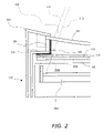
- FIG. 2 is an enlarged cross-sectional view of the left edge portion in FIG. 1 ;
- FIG. 3 is an exploded view of a liquid-crystal panel 101 , third spacers 105 , first spacers 301 and a backlight unit 113 , which are the main components of a liquid-crystal display device having a concavely curved panel according to Embodiment 1;
- FIG. 4 is a diagrammatic cross-sectional view illustrating the relation between the line of sight of a viewer observing the two edges of a concavely curved liquid-crystal panel and the horizontal width of the backlight;
- FIG. 5 is a diagram illustrating the relation between the line of sight of a viewer observing a concavely curved liquid-crystal panel, and the reflective plates/sheets;
- FIG. 6 is a diagrammatic cross-sectional view illustrating a state in which reflective plates are installed in a liquid-crystal display device having a concavely curved panel according to Embodiment 2;
- FIG. 7 is a diagrammatic cross-sectional view illustrating a method for forming/installing reflective plates in a liquid-crystal display device having a concavely curved panel according to Embodiment 3;
- FIG. 8 is a diagrammatic cross-sectional view illustrating a liquid-crystal display device having a concavely curved panel according to Embodiment 4;
- FIG. 9 is a diagrammatic cross-sectional view illustrating a liquid-crystal display device having a concavely curved panel according to Embodiment 5.
- FIG. 10 is an exploded view of the main components of a liquid-crystal display device having a concavely curved panel that is common to Embodiments 1 to 5.
- FIG. 10 is an exploded view of the main components of a liquid-crystal display device having a concavely curved panel, which is common to Embodiments 1 to 5.
- numeral 101 denotes a liquid-crystal panel
- numeral 301 denotes first spacers
- numeral 105 denotes third spacers
- numeral 302 denotes second spacers
- numeral 113 denotes a backlight unit.
- the liquid-crystal display devices according to embodiments of the present invention all have such a structure. The following is an explanation of the respective embodiments.
- FIG. 1 is a diagrammatic cross-sectional view illustrating a situation in which reflective plates are installed in a liquid-crystal display device having a concavely curved panel according to Embodiment 1.
- the liquid-crystal panel 101 is held by the third spacers 105 above the backlight unit 113 .
- Reflective plates 102 are installed on the inner wall of the third spacers 105 .
- the reflective plates are also installed on the spacers in the direction perpendicular to the third spacers 105 shown in FIG. 1 .
- Those perpendicular spacers are the first spacers 301 in FIG. 3 .
- the reflective plates are also installed on the inner walls of the first spacers 301 . It should be noted that FIG.
- FIG. 3 is an exploded view of the liquid-crystal panel 101 , the third spacers 105 , the first spacers 301 and the backlight unit 113 , which are the main components of the liquid-crystal display device having a concavely curved panel according to Embodiment 1.
- FIG. 10 is an exploded view showing the general locations where the reflective plates are installed.
- the reflective plates are installed on the inner walls of the first spacers 301 and the inner walls of the third spacers 105 , as indicated by the oblique lines.
- FIG. 2 is an enlarged cross-sectional view of the left edge portion in FIG. 1 .
- Optical sheets 115 , 115 and a dispersion plate 116 are installed below the gap 201 .
- a part of the frame of the backlight unit 113 functions as the spacer support portion 114 .
- the reflective plate 102 is installed on the inner wall of this narrow gap 201 . Through this measure, brightness non-uniformities at the edge portions 110 can be remedied.
- the presence of the third spacers 105 would pose an obstacle to such light rays, and there are no direct light rays that reach the viewer's eye from the light source 104 through the edge portion 110 of the liquid-crystal panel 101 . Consequently, even considering indirect light, at the edge portions of the liquid-crystal panel 101 , the amount of light rays reaching the viewer's eye after having passed through the liquid-crystal panel 101 from the rear side of the liquid-crystal panel 101 is smaller than at other portions of the liquid-crystal panel 101 .
- the reflective plates 102 are installed on the inner walls of the third spacers 105 , then the light rays 202 from the light source 104 are reflected at the reflective plates 102 , and incident on the viewer's eye through the line of sight 111 .
- this problem can also be solved by enlarging the width of the backlight unit 113 to a width corresponding to the front end of the line of sight 401 , as shown in FIG. 4 .
- the width of the backlight unit has to be enlarged, and as a result, the dimensions of the outer shape of the liquid-crystal display apparatus have to be made larger.
- FIG. 6 is a diagrammatic cross-sectional view illustrating the state in which reflective plates are installed in a liquid-crystal display device having a concavely curved panel according to Embodiment 2.
- the difference between the installation state of the reflective plates of the liquid-crystal display device having a concavely curved panel according to Embodiment 2 and the installation state of the reflective plates of the liquid-crystal display device having a concavely curved panel according to Embodiment 1 is that the reflective plates of the liquid-crystal display device having a concavely curved panel according to Embodiment 1 are also installed on components other than the spacers, whereas the reflective plates of the liquid-crystal display device having a concavely curved panel according to Embodiment 2 are not installed on any components other than the spacers.
- the attained effect does not reach the effect of the liquid-crystal display device having a concavely curved panel according to Embodiment 1, but the occurrence of brightness non-uniformities is to some extent better than if no reflective plates are provided, and also the manufacturing costs can be reduced slightly by omitting the process of installing reflective plates on the gap 201 .
- FIG. 7 is a diagrammatic cross-sectional view illustrating a method for forming/installing reflective plates in a liquid-crystal display device having a concavely curved panel according to Embodiment 3.
- the characteristic feature of the method for forming/installing reflective plates in a liquid-crystal display device having a concavely curved panel according to Embodiment 3 is the aspect that the reflective plates are constituted by a highly reflective material applied to the inner walls of the spacers. If the reflective plates are formed in this manner, the step of installing reflective plates on the spacers or the like becomes unnecessary, extremely thin reflective plates can be formed, and a slight contribution to making the overall liquid-crystal display device smaller can be made.
- FIG. 8 is a diagrammatic cross-sectional view illustrating a liquid-crystal display device having a concavely curved panel according to Embodiment 4.
- the characteristic feature of this liquid-crystal display device having a concavely curved panel according to Embodiment 4 is the aspect of making, for example, the spacers themselves of a highly reflective material, instead of attaching the reflective plates to spacers or the like or applying a highly reflective material on them.
- FIG. 9 is a diagrammatic cross-sectional view illustrating a liquid-crystal display device having a concavely curved panel according to Embodiment 5.
- the characteristic feature of this liquid-crystal display device having a concavely curved panel according to Embodiment 5 is the aspect that the locations where the reflective plates are installed are not only the third spacers 105 and the first spacers 301 supporting the concavely curved panel, but reflective plates are laid out on the inner walls of all components constituting the inner walls of the space enclosed by the liquid-crystal panel 101 and the backlight unit 108 , with the exception of the liquid-crystal panel 101 and transparent components through which the light that is emitted from the light source 104 is expected to pass.
- the components constituting the inner walls are the liquid-crystal panel 101 , the third spacers 105 , the spacer support portions 114 , the optical sheets 115 , 115 and the dispersion plate 116 .
- the optical sheets 115 , 115 and the dispersion plate 116 correspond to transparent components through which light emitted from the light source 104 can be expected to pass, so that the reflective plates are not installed thereon.
- the inner walls on which the reflective plates are installed are the third spacers 105 and the spacer support portions 114 , which are the portions marked by oblique lines in FIG. 9 .
- the occurrence of brightness non-uniformities at the edge portion 110 of the liquid-crystal panel 101 can be reduced to a minimum through installing the reflective plates.
Landscapes
- Physics & Mathematics (AREA)
- Nonlinear Science (AREA)
- Mathematical Physics (AREA)
- Chemical & Material Sciences (AREA)
- Crystallography & Structural Chemistry (AREA)
- General Physics & Mathematics (AREA)
- Optics & Photonics (AREA)
- Liquid Crystal (AREA)
- Planar Illumination Modules (AREA)
- Devices For Indicating Variable Information By Combining Individual Elements (AREA)
Abstract
Description
Claims (7)
Applications Claiming Priority (2)
| Application Number | Priority Date | Filing Date | Title |
|---|---|---|---|
| JPJP2005370436 | 2005-12-22 | ||
| JP2005370436A JP4481245B2 (en) | 2005-12-22 | 2005-12-22 | Curved liquid crystal display device and method for forming and installing reflector or reflector sheet for curved liquid crystal display device |
Publications (2)
| Publication Number | Publication Date |
|---|---|
| US20070146616A1 US20070146616A1 (en) | 2007-06-28 |
| US7609355B2 true US7609355B2 (en) | 2009-10-27 |
Family
ID=38184443
Family Applications (1)
| Application Number | Title | Priority Date | Filing Date |
|---|---|---|---|
| US11/423,960 Active 2027-12-07 US7609355B2 (en) | 2005-12-22 | 2006-06-14 | Curved liquid-crystal display device, and method for the forming and installation of reflective plate/sheet for curved liquid-crystal display device |
Country Status (3)
| Country | Link |
|---|---|
| US (1) | US7609355B2 (en) |
| JP (1) | JP4481245B2 (en) |
| CN (1) | CN100445833C (en) |
Cited By (11)
| Publication number | Priority date | Publication date | Assignee | Title |
|---|---|---|---|---|
| US20090059126A1 (en) * | 2007-09-05 | 2009-03-05 | Hitachi Displays, Ltd. | Display device |
| US20150116627A1 (en) * | 2013-10-30 | 2015-04-30 | Shenzhen China Star Optoelectronics Technology Co., Ltd. | Backlight module and liquid crystal display device using same |
| US20160109755A1 (en) * | 2014-10-21 | 2016-04-21 | Samsung Display Co., Ltd. | Display device |
| US20160120045A1 (en) * | 2014-10-23 | 2016-04-28 | Samsung Display Co., Ltd. | Display device |
| US9483964B2 (en) | 2014-04-07 | 2016-11-01 | Samsung Display Co., Ltd. | Display apparatus |
| US9523881B2 (en) | 2013-12-10 | 2016-12-20 | Samsung Display Co., Ltd. | Liquid crystal display device and manufacturing method thereof |
| US20170040400A1 (en) * | 2009-09-16 | 2017-02-09 | Semiconductor Energy Laboratory Co., Ltd. | Light-emitting device and manufacturing method thereof |
| US9625131B2 (en) | 2014-02-05 | 2017-04-18 | Samsung Display Co. Ltd. | Backlight unit and display device including the same |
| US20170205568A1 (en) * | 2016-01-15 | 2017-07-20 | Samsung Display Co., Ltd. | Backlight unit, display device, and method of manufacturing the display device |
| US10310171B2 (en) * | 2017-02-22 | 2019-06-04 | Minebea Mitsumi Inc. | Planar illumination apparatus |
| US11997859B2 (en) | 2009-09-16 | 2024-05-28 | Semiconductor Energy Laboratory Co., Ltd. | Light-emitting device and manufacturing method thereof |
Families Citing this family (28)
| Publication number | Priority date | Publication date | Assignee | Title |
|---|---|---|---|---|
| KR101385747B1 (en) * | 2007-09-21 | 2014-04-21 | 삼성전자주식회사 | Electronic paper display unit and portable communication terminal having the same |
| JP2009104946A (en) * | 2007-10-24 | 2009-05-14 | Sharp Corp | Light source device and liquid crystal display device |
| KR100951598B1 (en) * | 2008-05-26 | 2010-04-09 | (주)코텍 | Back light unit |
| US8477271B2 (en) * | 2008-12-26 | 2013-07-02 | Sharp Kabushiki Kaisha | Liquid crystal display device |
| JP5191920B2 (en) * | 2009-02-04 | 2013-05-08 | 株式会社ジャパンディスプレイイースト | Liquid crystal display |
| JP5187270B2 (en) * | 2009-05-13 | 2013-04-24 | 三菱電機株式会社 | Liquid crystal display device and liquid crystal display system |
| JP5654220B2 (en) | 2009-07-16 | 2015-01-14 | 株式会社ジャパンディスプレイ | Display device |
| TWI433071B (en) * | 2009-09-22 | 2014-04-01 | Ind Tech Res Inst | 3-d curved display device, fabrication method thereof and plastic display panel |
| CN101806970A (en) * | 2010-04-02 | 2010-08-18 | 友达光电股份有限公司 | Curved surface display panel |
| JP5659297B2 (en) * | 2011-04-28 | 2015-01-28 | ライオン株式会社 | Smoke-type volatilizer, smoke-type space treatment device, space treatment method |
| JP5806908B2 (en) * | 2011-10-14 | 2015-11-10 | シャープ株式会社 | Image display device |
| CA3078447C (en) | 2012-03-08 | 2022-05-10 | Simplehuman, Llc | Vanity mirror |
| CN103766333B (en) * | 2012-10-25 | 2017-10-27 | 狮王株式会社 | Sootiness type insecticide and sootiness type insect-killing device |
| KR20150012982A (en) | 2013-07-25 | 2015-02-04 | 삼성전자주식회사 | Display apparatus and control method for the same |
| KR101915733B1 (en) | 2013-08-02 | 2018-11-07 | 삼성디스플레이 주식회사 | Curved display device |
| KR101849339B1 (en) * | 2013-09-30 | 2018-04-17 | 삼성디스플레이 주식회사 | Flexible display device |
| CN103838036B (en) * | 2014-03-21 | 2016-05-04 | 深圳市华星光电技术有限公司 | Curved surface liquid crystal indicator |
| KR102183002B1 (en) * | 2014-09-02 | 2020-11-25 | 삼성전자주식회사 | Display apparatus and control method for the same |
| KR102130735B1 (en) * | 2014-09-03 | 2020-07-06 | 삼성전자주식회사 | Display apparatus |
| KR102301094B1 (en) * | 2014-12-23 | 2021-09-13 | 삼성디스플레이 주식회사 | Display device |
| CA2922596C (en) | 2015-03-06 | 2023-10-24 | Simplehuman, Llc | Vanity mirror |
| CN104714323A (en) * | 2015-03-12 | 2015-06-17 | 大庆金祥寓科技有限公司 | Micro-arc eyeshield liquid crystal |
| KR20170039022A (en) * | 2015-09-30 | 2017-04-10 | 삼성디스플레이 주식회사 | Display device |
| CN105158956A (en) * | 2015-10-30 | 2015-12-16 | 京东方科技集团股份有限公司 | Curved surface liquid crystal display |
| US10869537B2 (en) | 2017-03-17 | 2020-12-22 | Simplehuman, Llc | Vanity mirror |
| US11708031B2 (en) | 2018-03-22 | 2023-07-25 | Simplehuman, Llc | Voice-activated vanity mirror |
| EP3853073A4 (en) * | 2018-09-19 | 2022-11-16 | Simplehuman LLC | Vanity mirror |
| CA3131958A1 (en) | 2019-03-01 | 2020-09-10 | Simplehuman, Llc | Vanity mirror |
Citations (11)
| Publication number | Priority date | Publication date | Assignee | Title |
|---|---|---|---|---|
| JPS5852513Y2 (en) | 1977-12-28 | 1983-11-30 | 三菱電機株式会社 | gas concentration meter |
| US5307190A (en) * | 1991-08-19 | 1994-04-26 | Matsushita Electric Industrial Co., Ltd. | Ferroelectric liquid crystal panel and method of manufacturing same |
| JPH09197135A (en) | 1996-01-16 | 1997-07-31 | Matsushita Electric Ind Co Ltd | Plane illuminating device and liquid crystal display device provided with the illuminating device |
| US5672083A (en) * | 1993-06-22 | 1997-09-30 | Candescent Technologies Corporation | Fabrication of flat panel device having backplate that includes ceramic layer |
| US20010046008A1 (en) | 2000-04-21 | 2001-11-29 | Masahide Ueda | Multi-layer display panel and method of manufacturing the same |
| US6332690B1 (en) | 1997-10-22 | 2001-12-25 | Yazaki Corporation | Liquid crystal display with curved liquid crystal screen |
| US20020047952A1 (en) | 2000-08-03 | 2002-04-25 | Masayuki Kawata | Arm portable information apparatus |
| US6654071B2 (en) | 2001-06-13 | 2003-11-25 | Eturbotouch Technology Inc. | Flexible current-type touch control panel comprising a current-type touch control shield |
| US20060098153A1 (en) | 2002-11-22 | 2006-05-11 | Slikkerveer Peter J | Method of manufacturing a curved display |
| US7190503B2 (en) * | 2003-10-28 | 2007-03-13 | Seiko Epson Corporation | Electro-optical device, method of manufacturing the same, and electronic apparatus |
| US20070139605A1 (en) * | 2005-12-21 | 2007-06-21 | Nv Tech Co., Ltd. | Liquid Crystal Display Device and Method for Manufacturing Liquid Crystal Device |
Family Cites Families (3)
| Publication number | Priority date | Publication date | Assignee | Title |
|---|---|---|---|---|
| JP4216577B2 (en) * | 2002-12-20 | 2009-01-28 | シチズン電子株式会社 | Light guide plate |
| JP3847743B2 (en) * | 2003-10-22 | 2006-11-22 | 株式会社アドバンスト・ディスプレイ | Liquid crystal display device manufacturing method |
| JP3938134B2 (en) * | 2003-10-28 | 2007-06-27 | セイコーエプソン株式会社 | Electro-optical device and electronic apparatus using the same |
-
2005
- 2005-12-22 JP JP2005370436A patent/JP4481245B2/en active Active
-
2006
- 2006-03-15 CN CNB200610057450XA patent/CN100445833C/en active Active
- 2006-06-14 US US11/423,960 patent/US7609355B2/en active Active
Patent Citations (11)
| Publication number | Priority date | Publication date | Assignee | Title |
|---|---|---|---|---|
| JPS5852513Y2 (en) | 1977-12-28 | 1983-11-30 | 三菱電機株式会社 | gas concentration meter |
| US5307190A (en) * | 1991-08-19 | 1994-04-26 | Matsushita Electric Industrial Co., Ltd. | Ferroelectric liquid crystal panel and method of manufacturing same |
| US5672083A (en) * | 1993-06-22 | 1997-09-30 | Candescent Technologies Corporation | Fabrication of flat panel device having backplate that includes ceramic layer |
| JPH09197135A (en) | 1996-01-16 | 1997-07-31 | Matsushita Electric Ind Co Ltd | Plane illuminating device and liquid crystal display device provided with the illuminating device |
| US6332690B1 (en) | 1997-10-22 | 2001-12-25 | Yazaki Corporation | Liquid crystal display with curved liquid crystal screen |
| US20010046008A1 (en) | 2000-04-21 | 2001-11-29 | Masahide Ueda | Multi-layer display panel and method of manufacturing the same |
| US20020047952A1 (en) | 2000-08-03 | 2002-04-25 | Masayuki Kawata | Arm portable information apparatus |
| US6654071B2 (en) | 2001-06-13 | 2003-11-25 | Eturbotouch Technology Inc. | Flexible current-type touch control panel comprising a current-type touch control shield |
| US20060098153A1 (en) | 2002-11-22 | 2006-05-11 | Slikkerveer Peter J | Method of manufacturing a curved display |
| US7190503B2 (en) * | 2003-10-28 | 2007-03-13 | Seiko Epson Corporation | Electro-optical device, method of manufacturing the same, and electronic apparatus |
| US20070139605A1 (en) * | 2005-12-21 | 2007-06-21 | Nv Tech Co., Ltd. | Liquid Crystal Display Device and Method for Manufacturing Liquid Crystal Device |
Non-Patent Citations (3)
| Title |
|---|
| Notice of Allowance and fee due of U.S. Appl. No. 11/382,934 mailed on Mar. 6, 2009. |
| Office Action of U.S. Appl. No. 11/382,934 mailed on Apr. 3, 2008. |
| Office Action of U.S. Appl. No. 11/382,934 mailed on Nov. 26, 2008. |
Cited By (23)
| Publication number | Priority date | Publication date | Assignee | Title |
|---|---|---|---|---|
| US7826006B2 (en) * | 2007-09-05 | 2010-11-02 | Hitachi Displays, Ltd. | Display device |
| US20110019135A1 (en) * | 2007-09-05 | 2011-01-27 | Hitachi Displays, Ltd. | Display device |
| US7903196B2 (en) | 2007-09-05 | 2011-03-08 | Hitachi Displays, Ltd. | Display device |
| US20090059126A1 (en) * | 2007-09-05 | 2009-03-05 | Hitachi Displays, Ltd. | Display device |
| US20170040400A1 (en) * | 2009-09-16 | 2017-02-09 | Semiconductor Energy Laboratory Co., Ltd. | Light-emitting device and manufacturing method thereof |
| US11997859B2 (en) | 2009-09-16 | 2024-05-28 | Semiconductor Energy Laboratory Co., Ltd. | Light-emitting device and manufacturing method thereof |
| US11469387B2 (en) | 2009-09-16 | 2022-10-11 | Semiconductor Energy Laboratory Co., Ltd. | Light-emitting device and manufacturing method thereof |
| US11171298B2 (en) | 2009-09-16 | 2021-11-09 | Semiconductor Energy Laboratory Co., Ltd. | Light-emitting device and manufacturing method thereof |
| US10374184B2 (en) * | 2009-09-16 | 2019-08-06 | Semiconductor Energy Laboratory Co., Ltd. | Light-emitting device and manufacturing method thereof |
| US9280008B2 (en) * | 2013-10-30 | 2016-03-08 | Shenzhen China Star Optoelectronics Technology Co., Ltd. | Backlight module and liquid crystal display device using same |
| US20150116627A1 (en) * | 2013-10-30 | 2015-04-30 | Shenzhen China Star Optoelectronics Technology Co., Ltd. | Backlight module and liquid crystal display device using same |
| US10139672B2 (en) | 2013-12-10 | 2018-11-27 | Samsung Display Co., Ltd. | Liquid crystal display device |
| US9523881B2 (en) | 2013-12-10 | 2016-12-20 | Samsung Display Co., Ltd. | Liquid crystal display device and manufacturing method thereof |
| US9625131B2 (en) | 2014-02-05 | 2017-04-18 | Samsung Display Co. Ltd. | Backlight unit and display device including the same |
| US9483964B2 (en) | 2014-04-07 | 2016-11-01 | Samsung Display Co., Ltd. | Display apparatus |
| US10431169B2 (en) | 2014-10-21 | 2019-10-01 | Samsung Display Co., Ltd. | Display device |
| US9898975B2 (en) * | 2014-10-21 | 2018-02-20 | Samsung Display Co., Ltd. | Display device |
| US20160109755A1 (en) * | 2014-10-21 | 2016-04-21 | Samsung Display Co., Ltd. | Display device |
| US9746702B2 (en) * | 2014-10-23 | 2017-08-29 | Samsung Display Co., Ltd. | Display device |
| US20160120045A1 (en) * | 2014-10-23 | 2016-04-28 | Samsung Display Co., Ltd. | Display device |
| US10132991B2 (en) * | 2016-01-15 | 2018-11-20 | Samsung Display Co., Ltd. | Backlight unit, display device, and method of manufacturing the display device |
| US20170205568A1 (en) * | 2016-01-15 | 2017-07-20 | Samsung Display Co., Ltd. | Backlight unit, display device, and method of manufacturing the display device |
| US10310171B2 (en) * | 2017-02-22 | 2019-06-04 | Minebea Mitsumi Inc. | Planar illumination apparatus |
Also Published As
| Publication number | Publication date |
|---|---|
| US20070146616A1 (en) | 2007-06-28 |
| CN1987591A (en) | 2007-06-27 |
| JP2007171658A (en) | 2007-07-05 |
| CN100445833C (en) | 2008-12-24 |
| JP4481245B2 (en) | 2010-06-16 |
Similar Documents
| Publication | Publication Date | Title |
|---|---|---|
| US7609355B2 (en) | Curved liquid-crystal display device, and method for the forming and installation of reflective plate/sheet for curved liquid-crystal display device | |
| US7667786B2 (en) | Curved liquid-crystal display device and backlight used for curved liquid-crystal display device | |
| JP5059525B2 (en) | Liquid crystal display | |
| US10877308B2 (en) | Display device | |
| US8139177B2 (en) | Liquid crystal display device | |
| US9588264B2 (en) | Bezel-concealing display covers and display devices | |
| JP5026777B2 (en) | Curved liquid crystal panel and liquid crystal display device | |
| WO2012073929A1 (en) | Liquid crystal display device and multi-display system | |
| CN105093628A (en) | Splicing type display screen and assembling method thereof | |
| JP5187270B2 (en) | Liquid crystal display device and liquid crystal display system | |
| EP2189970A2 (en) | Display | |
| US20120182506A1 (en) | Optical film for reducing color shift and liquid crystal display having the same | |
| CN101907262A (en) | Positioning mechanism and back light module | |
| KR20150109743A (en) | Curved display device | |
| WO2013046604A1 (en) | Display device and multi-display device | |
| US8395719B2 (en) | Display device and light source block used therein | |
| JP5357016B2 (en) | Liquid crystal display | |
| KR20170000096A (en) | Bezel free multi-screen display device with transparent cover and fastening device of transparent cover | |
| KR102541703B1 (en) | Monitor Screen Transmission Area Expansion Plate and Monitor Screen Transmission Area Expansion System Using the Same | |
| JP2008033097A (en) | Fresnel lens sheet and transmission type screen | |
| CN113129759B (en) | Display module assembly and display device | |
| US20070139585A1 (en) | Double-sided liquid crystal display having differently sized optical film assemblies | |
| KR101408984B1 (en) | Liquid crystal panel assembly usable as mirror | |
| KR20010099170A (en) | Large screen flat panel display using slope fresnel lens | |
| KR20110103594A (en) | Diplay apparatus |
Legal Events
| Date | Code | Title | Description |
|---|---|---|---|
| AS | Assignment |
Owner name: NV TECH CO., LTD., JAPAN Free format text: ASSIGNMENT OF ASSIGNORS INTEREST;ASSIGNORS:NOUCHI, MASAHIRO;MATSUDA, FUMITOSHI;HASHIBA, HIROMITSU;REEL/FRAME:017777/0217 Effective date: 20060412 |
|
| AS | Assignment |
Owner name: INFOVISION OPTOELECTRONICS HOLDINGS LIMITED,VIRGIN Free format text: ASSIGNMENT OF ASSIGNORS INTEREST;ASSIGNOR:NVTECH CO., LTD.;REEL/FRAME:018229/0721 Effective date: 20060712 Owner name: INFOVISION OPTOELECTRONICS HOLDINGS LIMITED, VIRGI Free format text: ASSIGNMENT OF ASSIGNORS INTEREST;ASSIGNOR:NVTECH CO., LTD.;REEL/FRAME:018229/0721 Effective date: 20060712 |
|
| STCF | Information on status: patent grant |
Free format text: PATENTED CASE |
|
| FPAY | Fee payment |
Year of fee payment: 4 |
|
| FPAY | Fee payment |
Year of fee payment: 8 |
|
| MAFP | Maintenance fee payment |
Free format text: PAYMENT OF MAINTENANCE FEE, 12TH YEAR, LARGE ENTITY (ORIGINAL EVENT CODE: M1553); ENTITY STATUS OF PATENT OWNER: LARGE ENTITY Year of fee payment: 12 |