US7593490B2 - Joint synchronizer and decoder - Google Patents
Joint synchronizer and decoder Download PDFInfo
- Publication number
- US7593490B2 US7593490B2 US10/938,305 US93830504A US7593490B2 US 7593490 B2 US7593490 B2 US 7593490B2 US 93830504 A US93830504 A US 93830504A US 7593490 B2 US7593490 B2 US 7593490B2
- Authority
- US
- United States
- Prior art keywords
- decoder
- phase
- channel observations
- synchronization
- indication
- Prior art date
- Legal status (The legal status is an assumption and is not a legal conclusion. Google has not performed a legal analysis and makes no representation as to the accuracy of the status listed.)
- Active, expires
Links
Images


Classifications
-
- H—ELECTRICITY
- H04—ELECTRIC COMMUNICATION TECHNIQUE
- H04B—TRANSMISSION
- H04B7/00—Radio transmission systems, i.e. using radiation field
- H04B7/14—Relay systems
- H04B7/15—Active relay systems
- H04B7/185—Space-based or airborne stations; Stations for satellite systems
- H04B7/18523—Satellite systems for providing broadcast service to terrestrial stations, i.e. broadcast satellite service
-
- H—ELECTRICITY
- H04—ELECTRIC COMMUNICATION TECHNIQUE
- H04L—TRANSMISSION OF DIGITAL INFORMATION, e.g. TELEGRAPHIC COMMUNICATION
- H04L27/00—Modulated-carrier systems
- H04L27/18—Phase-modulated carrier systems, i.e. using phase-shift keying
- H04L27/22—Demodulator circuits; Receiver circuits
-
- H—ELECTRICITY
- H04—ELECTRIC COMMUNICATION TECHNIQUE
- H04L—TRANSMISSION OF DIGITAL INFORMATION, e.g. TELEGRAPHIC COMMUNICATION
- H04L27/00—Modulated-carrier systems
- H04L27/26—Systems using multi-frequency codes
- H04L27/2601—Multicarrier modulation systems
- H04L27/2647—Arrangements specific to the receiver only
- H04L27/2655—Synchronisation arrangements
- H04L27/2657—Carrier synchronisation
-
- H—ELECTRICITY
- H04—ELECTRIC COMMUNICATION TECHNIQUE
- H04L—TRANSMISSION OF DIGITAL INFORMATION, e.g. TELEGRAPHIC COMMUNICATION
- H04L27/00—Modulated-carrier systems
- H04L27/26—Systems using multi-frequency codes
- H04L27/2601—Multicarrier modulation systems
- H04L27/2647—Arrangements specific to the receiver only
- H04L27/2655—Synchronisation arrangements
- H04L27/2662—Symbol synchronisation
-
- H—ELECTRICITY
- H04—ELECTRIC COMMUNICATION TECHNIQUE
- H04L—TRANSMISSION OF DIGITAL INFORMATION, e.g. TELEGRAPHIC COMMUNICATION
- H04L27/00—Modulated-carrier systems
- H04L27/26—Systems using multi-frequency codes
- H04L27/2601—Multicarrier modulation systems
- H04L27/2647—Arrangements specific to the receiver only
- H04L27/2655—Synchronisation arrangements
- H04L27/2668—Details of algorithms
- H04L27/2673—Details of algorithms characterised by synchronisation parameters
- H04L27/2676—Blind, i.e. without using known symbols
- H04L27/2679—Decision-aided
-
- H—ELECTRICITY
- H04—ELECTRIC COMMUNICATION TECHNIQUE
- H04L—TRANSMISSION OF DIGITAL INFORMATION, e.g. TELEGRAPHIC COMMUNICATION
- H04L27/00—Modulated-carrier systems
- H04L27/0014—Carrier regulation
- H04L2027/0024—Carrier regulation at the receiver end
- H04L2027/0026—Correction of carrier offset
- H04L2027/0034—Correction of carrier offset using hypothesis testing
-
- H—ELECTRICITY
- H04—ELECTRIC COMMUNICATION TECHNIQUE
- H04L—TRANSMISSION OF DIGITAL INFORMATION, e.g. TELEGRAPHIC COMMUNICATION
- H04L27/00—Modulated-carrier systems
- H04L27/0014—Carrier regulation
- H04L2027/0044—Control loops for carrier regulation
- H04L2027/0046—Open loops
-
- H—ELECTRICITY
- H04—ELECTRIC COMMUNICATION TECHNIQUE
- H04L—TRANSMISSION OF DIGITAL INFORMATION, e.g. TELEGRAPHIC COMMUNICATION
- H04L27/00—Modulated-carrier systems
- H04L27/0014—Carrier regulation
- H04L2027/0044—Control loops for carrier regulation
- H04L2027/0063—Elements of loops
- H04L2027/0065—Frequency error detectors
-
- H—ELECTRICITY
- H04—ELECTRIC COMMUNICATION TECHNIQUE
- H04L—TRANSMISSION OF DIGITAL INFORMATION, e.g. TELEGRAPHIC COMMUNICATION
- H04L27/00—Modulated-carrier systems
- H04L27/26—Systems using multi-frequency codes
- H04L27/2601—Multicarrier modulation systems
- H04L27/2647—Arrangements specific to the receiver only
- H04L27/2655—Synchronisation arrangements
- H04L27/2689—Link with other circuits, i.e. special connections between synchronisation arrangements and other circuits for achieving synchronisation
- H04L27/2695—Link with other circuits, i.e. special connections between synchronisation arrangements and other circuits for achieving synchronisation with channel estimation, e.g. determination of delay spread, derivative or peak tracking
Definitions
- the present invention is directed generally to digital signal processing techniques for burst-mode data signals having short observation lengths in an environment experiencing a low signal-to-noise ratio (SNR).
- the invention is more particularly but not exclusively directed to a joint synchronizer and decoder (JSD) adapted for use in burst-mode phase shift key (PSK) modulation systems based on the Digital-Video Broadcast Return Channel via Satellite (DVB-RCS) standard.
- JSD joint synchronizer and decoder
- PSK phase shift key
- satellites for the transmission of voice and data communication signals has greatly expanded over the past decade, and satellite links are now routinely used and relied upon for global, almost instant, bi-directional communications. Rapid improvements in satellite communications have produced beneficial impacts on many segments of society from business and commercial applications to consumer products. For example, residences throughout the world now receive news and entertainment broadcasts via satellite, in nearly real-time from sites in almost any country.
- Burst-mode communication techniques and the related synchronization techniques are frequently used in satellite voice and data transmissions. These systems typically employ multiple transmitters that send “bursts” of transmissions to a receiver. Bursts from the different transmitters are coordinated in time and frequency such that each transmitter can communicate with the receiver without interfering with each other.
- TDMA Time Division Multiple Access
- TDM time-division multiplexing
- TDM divides the carrier wave into time slots and then allocates those time slots to the different data signals. Effectively, each of the data signals takes turns accessing the carrier wave, thereby allowing a single carrier wave to carry multiple simultaneous data transmission.
- a Multi-Frequency Time Division Multiple Access (MF-TDMA) receiver simultaneously receives TDMA signals on several different carrier frequencies.
- MF-TDMA data transmission scheme any user can potentially transmit data at any frequency at any time.
- the actual time slot and frequency allocation to each user is based on capacity requests submitted by the terminal.
- phase shift keying data modulation
- each symbol can be represented as a phasor in which the phase state of the symbol at the correct detection instant, or the relative change in phase from symbol to symbol, represents data.
- This data in turn, can be expressed as a corresponding bit or combination of bits in which the number of bits corresponds to the number of possible phase states used for data modulation.
- BPSK binary phase shift keying
- each symbol may have one of two phase states (i.e., 0, ⁇ ).
- Each BPSK symbol can therefore represent a single binary digit (bit).
- each symbol may have one of four phase states (i.e., 0, ⁇ /2, ⁇ and 3 ⁇ /2). Each QPSK symbol can therefore represent two binary digits.
- MF-TDMA signals are de-multiplexed and re-arranged to form a signal equivalent to a single carrier.
- the single-carrier data signal is then demodulated to recover the underlying data.
- the demultiplexing and demodulation steps are well known in the field of communications and are the subject of extensive research and development to improve transmission speeds, bandwidth, accuracy, and reliability.
- DVB-S Digital Video Broadcast by Satellite
- ETSI European Telecommunications Standards Institute
- This standard relates to DVB services and transparent satellite communication systems to provide DVB-S services directly to the user through an integrated receiver/decoder device that is located in the user's home.
- the versatility of DVB-S in multiplexing permits the use of a transmission capacity encompassing a variety of television service configurations, including sound and data services.
- the components of the DVB-S services are transmitted on a TDM carrier wave.
- DVB-S standard please refer to ETSI publication EN 300 421 V1.1.2 (1997-98), entitled “Digital Video Broadcasting (DVB); Framing Structure, Channel Coding and Modulation for 11/12 GHz Satellite Services,” the subject matter of which is hereby incorporated herein by reference.
- Satellite broadcasts are also increasingly used for instantaneous two-way audio, video, and data communications. Accordingly, recent attention has been given to the demand for making satellite communications interactive so that recipients of the broadcast can also communicate back to the origin of the transmission. For example, satellite communications can be used to provide Internet connections between different users.
- satellite communications can be used to provide Internet connections between different users.
- DVD-RCS digital video broadcast with return channel by satellite
- the DVB-RCS standard relates to interaction channels on a satellite distribution system.
- the purpose of this standard is to provide basic specifications for providing interaction channels for interactive networks based on geostationary (GEO) satellites that incorporate return channel satellite terminals (RCST).
- GEO geostationary
- RCST return channel satellite terminals
- the DVB-RCS standard facilitates the use of RCSTs for domestic installations both individual and collective types.
- the DVB-RCS standard likewise supports the connection of the terminals with home data networks, and can be applied to all frequency bands allocated to GEO satellite services.
- ETSI publication EN 301 790 v.1.3.1, dated 2003-03, entitled “Digital Video Broadcasting (DVB); Interaction Channel for Satellite Distribution Systems,” the subject matter of which is hereby incorporated herein by reference.
- Satellite communication systems operating under the DVB-RCS standard can exchange data using a variety of network and Internet technologies.
- the DVB-RCS standard accommodates Asynchronous Transfer Mode (ATM) technology for transferring data in cells or packets of a fixed size.
- ATM Asynchronous Transfer Mode
- the data packet used with ATM is relatively small compared to packets used with older technologies.
- the small, constant packet size allows ATM equipment to transmit video, audio, and computer data over the same network, and helps assure fairness.
- ATM creates a fixed channel, or route, between two points whenever data transfer begins, unlike TCP/IP that divides messages into packets that can each take a different route from source to destination.
- the DVB-RCS standard may also be used to transmit MPEGs (Moving Picture Experts Group), a family of digital video compression standards and file formats that achieve high compression rate by storing only the changes from one frame to another, instead of each entire frame.
- MPEGs Moving Picture Experts Group
- Loss of bursts (or packets), as measured by packet loss ratio, is a main performance criterion under DVB-RCS. Due to a long propagation delay in geostationary satellite communications, the packet loss ratio should be low in order to avoid performance degradation at higher network layers.
- the human senses are generally tolerant of slight variations, so for the transmission of video and sound broadcasts, as defined by DVB-RCS, the packet loss ratios is preferably in the order of 1 ⁇ 10 ⁇ 5 , so that less than one packet is lost per hundred-thousand burst signals. For more stringent types of data transmissions, a lower packet loss may be needed, such as 1 ⁇ 10 ⁇ 7 , where less than 1 packet is lost per ten million packet transmissions.
- One way to decrease the packet loss is to increase the signal transmission strength or effective isotropic radiated Power (EIRP) of the transmitter, thereby increasing the signal-to-noise ratio at the receiver.
- EIRP effective isotropic radiated Power
- Improvements in the signal-to-noise ratio are desirable because, as provided by Shannon's theorem, the ultimate theoretical limit to the data transmission transfer rate on a communications channel is directly proportional the signal-to-noise ratio of that channel. Consequently, increasing the power transmitted on the return channel can often be a solution to provide adequately reliable communications. However, increasing the transmission power of the receiver unacceptably increases the cost of the receiver.
- DVB-RCS system application Another important aspect of DVB-RCS system application is the provision of services at K a -band frequencies (e.g., 30 GHz uplink from terminals to satellite).
- K a -band frequencies e.g., 30 GHz uplink from terminals to satellite.
- the cost of the user terminal plays a major role in the business model of this type of services.
- RF components of the terminals are costly. Less expensive RF components result in tighter link budget on the uplink from the terminal to satellite.
- the use of very power efficient modems is essential in order to maintain acceptable level of system availability.
- the change in spatial location causes the propagation path length and the signal propagation time to change, and the change in relative velocities causes a Doppler frequency to change the frequency of the burst-mode signal when it is received at the intended receiver.
- the burst-mode signals originally transmitted at fixed intervals, arrive at varying time intervals.
- varying weather conditions such as clouds and rain, also affect the communication signals.
- contributors to the carrier frequency offset include movement of the satellite which creates a satellite Doppler effect, uncertainty due to the satellite's transponder, uncertainty or changes at the transmitter as to the exact carrier frequency, and length and atmospheric conditions en route.
- synchronization is a fine-tuning value for best receiver performance.
- the synchronization process generally includes signal detection, finding the right timing (i.e., the symbol timing), finding the carrier frequency offset, and tracking the carrier phase. After the right combination of these factors is determined, thereby enabling synchronization, the data signal is demodulated from the carrier wave and the encoded symbols represented by the data signal is passed to a decoder to extract and deliver the payload data in the burst.
- synchronization methods usually operate at relatively high signal-to-noise ratio that allow reliable synchronization.
- conventional burst signal demodulation techniques perform synchronization and then the decoding in a serial manner.
- a receiver generally includes a cascade of receiving filter, synchronization, and decoding to process received burst signals. Since the return channel is operating at a very low signal-to-noise ratio, carrier synchronization using this traditional approach cannot alone give the right signal constellation.
- the currently known techniques for improving synchronization estimations generally rely on certain threshold criteria, such as having a sufficiently high signal-to-noise ratio, to determine the points where the synchronization problem occurs. When falling below the threshold value, the conventional algorithms fail to operate properly. Much of the current research and development is directed toward developing techniques to reduce this threshold level.
- the present invention meets the needs described above in a joint synchronizer and decoder (JSD) that elects among multiple candidates for a signal distortion parameter based on a measure of decoding success.
- JSD joint synchronizer and decoder
- This process which is referred to as “decision aided candidate selection,” increases the likelihood of selecting the correct estimate of the signal distortion parameter when the signal-to-noise ratio declines to the point where the noise may mask the signal distortion parameter.
- a receiver utilizing this technology can identify the correct signal distortion parameter, and thereby maintain synchronization, at a lower signal-to-noise ratio than a conventional receiver.
- This allows the transmitter to meet a required data loss standard at a lower power level and cost, which is particularly advantageous in a system with price sensitive transmitters such as return channel transmitters in a satellite communication systems operating under the DBV-RCS standard.
- one source of signal distortion is carrier frequency offset
- the carrier frequency offset candidates represent several of the largest local maxima values in a modulation-free frequency spectrum of the input signal.
- selecting among multiple candidates for the carrier frequency offset increases the likelihood of selecting the correct carrier frequency offset when the signal-to-noise ratio declines to the point where the largest frequency in the modulation-free frequency spectrum may correspond to noise, rather than to the correct carrier frequency offset.
- the JSD itself is independent of the source of estimates of the signal distortion, and may be used to process multiple candidates for sources of signal distortion other than carrier frequency offset.
- the JSD may also implement a feedback loop in the decoding and phase tracking process referred to as “decision directed phase tracking.”
- this process an indicator of decoding success is used as a feedback parameter in the phase tracking process.
- This invention represents a major improvement in synchronization technology for burst-mode communication systems, which again allows the transmitter to meet a required data loss standard at a lower the power level and cost.
- the invention may be implemented as a JSD that operates on an input signal modulated with encoded data.
- the JSD includes a number of channel observation modifiers that each receives an associated candidate signal distortion indicator and channel observations associated with the input signal. Each channel observation modifier also produces modified channel observations including the encoded data based on the associated candidate signal distortion indicator and the channel observations.
- the JSD also includes a synchronization processor associated with each channel observation modifier. Each synchronization processor receives modified channel observations from its associated channel observation modifier, synchronizes to the modified channel observations received from its associated channel observation modifier, and produces corrected channel observations.
- the JSD also includes a partial decoder associated with each synchronization processor.
- Each partial decoder partially decodes the encoded data embedded within the corrected channel observations received from its associated synchronization processor and produces an associated indication of decoding success. This allows a branch selector to select a signal distortion indicator for decode processing based on a comparison of the indications of decoding success received from the partial decoders.
- the invention may also be practiced as a JSD that includes an iterative processor that receives and synchronizes to channel observations associated with an input signal.
- the iterative processor includes a decoder that decodes the synchronized channel observations received from a synchronization processor and produces an associated indication of decoding success.
- the iterative processor also includes a feedback loop that supplies the indication of decoding success to the synchronization processor. This allows the synchronization processor to adjust its synchronization to the channel observations based on the indication of decoding success.
- the iterative processor may also include a soft decision aided synchronization processor operative for computing a synchronization parameter based on the indication of decoding success.
- the soft decision aided synchronization processor also computes corrected channel observations based on the input channel observations and the synchronization parameter.
- the input signal to the JSD may include burst-mode multi-frequency time division multiplexed (MF-TDMA) data in which the data signal is encoded using a quadrature phase shift key (QPSK) modulation technique in accordance with the digital video broadcast return channel via satellite(DVB-RCS) standard.
- the JSD may also include a channel observer for processing the input signal to produce the channel observations. More specifically, the channel observer may include a front-end analog processor that amplifies the input signal, down-converts the amplified input signal to obtain an intermediate frequency signal, and filters the intermediate frequency signal.
- the channel observer may also include a digital preliminary processor that digitizes a representation of the input signal to obtain a digital MF-TDMA signal, demultiplexes the MF-TDMA signal to obtain a concatenated single-channel TDMA signal, and detects burst-mode data packets within the single-channel TDMA signal to obtain the channel observations.
- a digital preliminary processor that digitizes a representation of the input signal to obtain a digital MF-TDMA signal, demultiplexes the MF-TDMA signal to obtain a concatenated single-channel TDMA signal, and detects burst-mode data packets within the single-channel TDMA signal to obtain the channel observations.
- the encoded data typically includes a number of symbols
- the indication of decoding success typically includes a log likelihood ratio (LLR) produced by the partial decoder for each symbol
- the branch selector typically selects a signal distortion indicator based on the highest average log likelihood ratio for each symbol over a common range of the symbols.
- LLR log likelihood ratio
- the JSD includes a number of frequency correctors. Each frequency corrector receives an associated carrier frequency offset candidate and channel observations associated with the input signal. Each frequency corrector also produces modified. channel observations including the encoded data based on the associated carrier frequency offset candidate and the channel observations.
- the JSD also includes an initial phase estimator and corrector configured to initialize the modified channel observations to an initial phase.
- This embodiment of the JSD also includes a phase tracking module associated with each frequency corrector. Each phase tracking module synchronizes to the initialized and modified channel observations received from its associated initial phase estimator and corrector to produce phase corrected channel observations.
- the JSD also includes a partial decoder associated with each phase tracking module. Each partial decoder partially decodes the encoded data embedded within the phase corrected channel observations received from its associated phase tracking module and produces an associated indication of decoding success.
- the JSD also includes a branch selector that selects a carrier frequency offset candidate for decode processing based on a comparison of the indications of decoding success received from the partial decoders.
- the invention may also be practiced as a JSD that includes a decoder assisted phase tracker.
- This module receives and synchronizes to channel observations associated with the input signal and produces phase corrected channel observations.
- the JSD also includes a decoder that decodes the phase corrected channel observations received from the decoder assisted phase tracker and produces an associated indication of decoding success.
- the JSD also includes a feedback loop that supplies the indication of decoding success to the decoder assisted phase tracker. This allows the decoder assisted phase tracker to adjust its synchronization to the channel observations based on the indication of decoding success.
- the indication of decoding success typically includes a log likelihood ratio produced by the decoder.
- the encoded data typically defines systematic bits representing unknown data and parity bits derived from the systematic bits.
- the decoder assisted phase tracker may include a soft decision aided phase tracker that computes a phase tracking parameter based on the systematic bits and the indication of decoding success.
- the soft decision aided phase tracker may also compute corrected channel observations based on the systematic bits and the phase tracking parameter.
- the decoder assisted phase tracker may also include a phase tracking module that receives the phase tracking parameter from the soft decision aided phase tracker and computes a corrected channel observations based on the parity bits and the phase tracking parameter.
- the decoder assisted phase tracker also includes a switch that feeds the systematic bits to the soft decision aided phase tracker. The switch also feeds the parity bits to the phase tracking module.
- the phase tracking module also typically includes a feedback loop that includes a phase tracking parameter associated with the corrected channel observations.
- the soft decision aided phase tracker typically computes the phase tracking parameter by removing modulation from the channel observations, obtaining a resultant signal by weighting the modulation-free channel observations by a representation of the indication of decoding success, and computing a sliding average of the resultant signal.
- FIG. 1 is a block diagram of a satellite communication system in which the present invention may be deployed.
- FIG. 2 is a conceptual drawing of the prior art showing a burst-mode data packet illustrating quadrature phase shift keying as a data modulation technique.
- FIG. 3 is a conceptual drawing of the prior art showing data symbols illustrating the signal distortion effect of a carrier frequency offset.
- FIG. 4 is a conceptual drawing of the prior art showing a burst-mode data packet illustrating a measure for carrier frequency offset.
- FIG. 5 is a logic flow diagram illustrating a method for operating a generalized joint synchronizer and decoder.
- FIG. 6 is a logic flow diagram illustrating a method for operating a joint synchronizer and decoder implementing decision aided carrier frequency offset estimation and decision aided phase tracking.
- FIG. 7 is a block diagram of a return channel receiver in a satellite communication system including a joint synchronizer and decoder.
- FIG. 8 is a block diagram of a prior art channel observer in a return channel receiver in a satellite communication system.
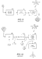
- FIG. 9 is a block diagram of a prior art front-end analog processor in a return channel receiver in a satellite communication system.
- FIG. 10 is a block diagram of a prior art digital preliminary processor in a return channel receiver in a satellite communication system.
- FIG. 11 is a block diagram of a generalized joint synchronizer and decoder.
- FIG. 12 is a block diagram of a joint synchronizer and decoder configured to implement decision aided carrier frequency offset estimation and decision aided phase tracking.
- FIG. 13 is a block diagram of a phase tracking module for the joint synchronizer and decoder.
- FIG. 14 is a block diagram of a partial decoder for the joint synchronizer and decoder.
- FIG. 15 is a block diagram of an iterative processor for the joint synchronizer and decoder.
- FIG. 16 is a block diagram of a decoder assisted phase tracker for the iterative processor of the joint synchronizer and decoder.
- FIG. 17 is a block diagram of a phase tracking module for the decoder assisted phase tracker.
- JDS joint synchronizer and decoder
- the rationale for the decoder assisted frequency correction is to allow the production of high quality parameter estimates at a low signal-to-noise ratio.
- a parameter that plays important role in synchronization is the carrier frequency offset. It is essential to obtain an accurate estimate of the carrier frequency offset and correct the channel observations accordingly before actual signal decoding.
- the carrier frequency offset It is assumed that more than one candidate for the carrier frequency offset is available. It should be noted that a single estimate based on conventional estimation rules that ignore the underlying coding structure are occasionally far from the true value. This type of error in estimation is sometimes referred to as an “outlier.” Unfortunately, the probability of encountering an outlier increases when the signal-to-noise ratio decreases. The JSD takes advantage of the recognition that it is highly likely that the right estimate can be found among a fairly small number of candidates.
- the proposed JSD takes advantage of the log-likelihood ratios (LLR) output from the soft-input-soft-output decoding algorithms as indications of decoding success. That is, the soft decision outputs (LLR values) of each decoder are used to establish a measure of likelihood of decoding success, so that one branch exhibiting the best indication of decoding success based on partial decoding can be selected for further processing.
- the mean absolute value of the soft decisions (LLR values) is used as a measure of merit of each branch.
- the soft decision values are computed for both systematic and parity bits. A branch with a small frequency estimate error is more likely to have a high average soft-decision value. Based on simulation results, one or two iterations of decoding in each branch is adequate to establish a good likelihood measure.
- This JSD also implements methods for iterative improvement of channel observation based on an estimate of the carrier phase within each iteration loop.
- the soft decision values provided by the decoders are used to estimate and correct the phase variation over a block of channel observation.
- the JSD typically implements two decision aided processes, which are referred to as “decision aided candidate selection” and “decision aided synchronization and decoding.”
- “decision aided candidate selection” may be used to select a carrier frequency offset by selecting among a number of candidates for this parameter based on an indication of decoding success.
- “decision aided synchronization and decoding” may be used for phase tracking based on an indication of decoding success.
- the JSD is employed to track and remove signal distortion caused by carrier frequency offset so that this particular source of signal distortion can be removed to improve the ability of the receiver to maintain synchronization in low signal-to-noise conditions.
- carrier frequency offset is an important source of signal distortion in any communication system using a phase shift keying modulation technique because the carrier frequency offset directly influences the phase characteristic of the modulating signal. Nevertheless, is should be appreciated that the invention may be applied to the identification and removal of other types of signal distortion that may be more significant in other types of communications systems.
- the JSD may be applied to track and remove other types of signal distortion, such as phase noise or the combination of phase noise and carrier frequency offset, in any type of suitable device, such as a return channel receiver operating in accordance with the DVB-RCS standard. Accordingly, it should be understood that carrier frequency offset correction is one important application of the JSD, but that it may also be used to track and remove other types of signal distortion, and may be used for modulation systems other than phase shift keying.
- the JSD is described below in the context of a return channel receiver operating in accordance with the DVB-RCS standard, but may operate under other standards.
- the JSD is shown as operating in the return channel receiver of a ground-station hub of within a “bent pipe” satellite communication system, which is an important application of the invention.
- the invention may also be deployed as on board processing (OBP) on the satellite or other communication platform, such as an airplane, missile or spacecraft.
- OBP on board processing
- Embodiments of the invention may also be deployed in a terminal-to-terminal “mesh” communication system, or in any other suitable type of communication system.
- the DVB-RCS standard relies on MF-TDMA burst-mode, packetized communications using quadrature phase shift key (QPSK) data modulation.
- QPSK quadrature phase shift key
- individual data packets are turbo decoded and include known symbols in a preamble and unknown data in a payload.
- a typical preamble length is 48 symbols.
- a typical length of the unknown payload portion of the data packet is 440 symbols. It should be understood that these parameters may all be varied for embodiments of the invention utilizing different communication techniques.
- known symbols also referred to as “pilot” symbols, need not be located with a data packet preamble, but may be located anywhere within, and may be distributed throughout, the data packet.
- an important purpose for deploying the JSD is to minimize the required return channel transmission power required to maintain acceptable data loss levels for a satellite communications system operating under the DVB-RCS standard. Nevertheless, by tracking and removing carrier frequency offset, the invention improves communication synchronization even in situations when increasing the return channel transmission power alone may not be successful. This situation may occur, for example, during rain fade conditions or other circumstances that increase or cause fluctuations in the carrier frequency offset.
- signal distortion indicators such as carrier frequency offset candidates
- signal distortion indicators are preferably received from a particular embodiment of a signal distortion estimator as described in U.S. patent application Ser. No. 10/938,299 entitled “Hybrid Frequency Offset Estimator,” which is incorporated herein by reference.
- the signal distortion indicators could be received from any other suitable type of device.
- the signal distortion estimator such as a hybrid frequency offset estimator, and the JSD may be integrated into a single piece of equipment or they may be distributed.
- the signal distortion estimator may be located on a satellite as on-board-processing (OBP) equipment, whereas the JSD may be located in ground-based receiver configured as customer premises equipment (CPE).
- OBP on-board-processing
- CPE customer premises equipment
- any other division of data processing functionality may be deployed to suit a particular application.
- carrier phase and frequency synchronization is but one kind of synchronization
- turbo decoding is but one kind of decoding scheme that may be applied to burst signals.
- the particular architecture described, while presented as applied to a DVB-RCS system using these technologies, is not limited to DVB-RCS and has application in other systems faced with the same or similar types of problems.
- the invention can be applied to any type of iterative decoding principle but is not limited to turbo decoding nor to any particular type of turbo decoding.
- the method described can be used for different types of coding; likewise, while the embodiment discussed is that of a carrier synchronization, this again is but one part of “synchronization,” and the idea can also be generalized so that for any particular part of synchronization that is lacking the necessary performance, the joint collaboration between decoding and synchronization of this invention can be equally applied.
- the method taught does apply to burst-mode signals in every instance.
- an embodiment of the invention may be applied to a continuous mode of data transmission.
- the principles of the invention taught herein with respect to burst-mode signals may also find application to other types of transmissions and the described method and structure is not to be taken as necessarily limiting in this regard. Nevertheless, it should also be appreciated that the problem sought to be overcome by the invention occurs when there are very short observations of the signal, which occurs with a TDMA burst-mode type of signal. This is when joint synchronization and decoding come into the picture most acutely.
- the carrier frequency offset estimator module and the JSD module conveniently interface at the output of the frequency offset estimator module, which typically outputs several candidate values for the carrier frequency offset.
- the number of candidates produced by the carrier frequency offset estimator could be any number the designer chooses, realizing that the system complexity grows with an increase in this number. Three candidates are used in the exemplary embodiments. However, any number of candidates could produced depending on the particular application of the invention.
- FIG. 1 is a block diagram of a “bent pipe” satellite communication system 10 in which the present invention may be deployed.
- This type of satellite communication system includes a satellite 20 , a number of ground station hubs represented by the hub 30 and a larger number of end-user terminals represented by the terminal 40 .
- this simplified configuration is typical of satellite-based broadcast television systems in which the hub 30 broadcasts television signals to the terminal 40 under the DVB-S standard.
- this infrastructure for bi-directional communications under the DVB-RCS standard, for example to implement interactive television or Internet service for the receivers.
- the terminal 40 typically sends return channel communications 50 back to the hub 30 , which includes a return channel receiver 60 configured to receive and decode these communications.
- the invention may be embodied within a demodulator 62 , which typically includes a signal distortion estimator such as a carrier frequency offset estimator, deployed within the return channel receiver 60 .
- the DVB-RCS standard specifies the characteristics of the return channel communications 50 , which are in multi-frequency time division multiple access (MF-TDMA) burst-mode packet format using quadrature phase shift key (QPSK). data modulation.
- the encoded data is preferably decoded using turbo decoding techniques, which are well known in the field of satellite communications.
- the present invention may be embodied as a frequency offset estimator within the return channel receiver 60 . The challenge is to reliably determine the carrier frequency offset in return channel signal 50 , and thereby allow the return channel receiver 60 maintain synchronism with the return channel.
- the objective includes meting the typical DVB-RCS packet loss criteria of 1 ⁇ 10 ⁇ 5 (less than one packet is lost per hundred-thousand burst signals) and 1 ⁇ 10 ⁇ 7 (less than 1 packet is lost per ten million packet transmissions), as appropriate, without having to increase the return channel transmission power of the terminal 40 .
- This objective becomes increasingly challenging as the signal-to-noise ratio decreases (i.e., the return channel signal 50 becomes increasingly faint).
- the faint return signal problem can be compounded when conditions cause the carrier frequency offset fluctuate, which can occur, for example, during fluctuating cloud and rain fade conditions.
- FIG. 2 is a conceptual drawing of a burst-mode data packet 70 illustrating the quadrature phase shift keying (QPSK) data modulation technique specified by the DVB-RCS standard.
- the data packet 70 includes a 48 symbol preamble 80 followed by a 440 symbol payload 90 .
- the preamble 80 includes pilot symbols, which are specified in advance and known by the receiver. In general, any number of pilot symbols may be located anywhere or distributed throughout the data packet 70 , but the DVB-RCS standard specifies that pilot symbols are located in a preamble 80 of the data packet. These known symbols are typically used for signal detection, synchronization, and so forth.
- the payload 90 includes the unknown data of the underlying, substantive data transmission.
- the symbols of the payload 90 may also include substantive data as well as error checking or other bits used for administration of the system.
- the payload 90 under the DVB-RCS standard includes “systematic bits” defining substantive data as wells as “parity bits” used for error checking.
- each symbol in the data packet 70 is a phasor, represented by the phasors 92 a - n , in which modulating data is expressed as the symbol phase angle.
- each symbol may have four states (i.e., 0, ⁇ /2, ⁇ and 3 ⁇ /2).
- each symbol may be translated into a two-bit binary representation.
- each symbol may have two states (i.e., 0, ⁇ ) and can therefore be represented by a single binary bit.
- the symbols are generally represented by the designation Z(n), and a sample or measurement of the symbol is generally referred to as “channel observations” represented by the designation Z′(n). That is, the nominal, intended or undistorted baseband data signal is generally represented by the designation Z(n), whereas the actual (distorted or corrupted) channel observations (for example as distorted or corrupted by the carrier frequency offset) is generally represented by the designation Z′(n).
- the signal processing operation of the signal distortion estimator can, therefore, be expressed as detecting candidates for the carrier frequency offset in the channel observations Z′(n) which are used to reconstruct estimates of the undistorted symbol sequence Z(n).
- FIG. 3 is a conceptual drawing of data symbols illustrating the signal distortion effect of a carrier frequency offset.
- the carrier frequency offset causes the symbol phase angle to be offset (rotated) slightly from its nominal or expected value.
- the symbol phase angle is offset by one percent or 3.6°.
- a frequency offset accumulates in phase over time, which causes the phase offset within a data packet to increase from symbol to symbol.
- a one percent (1%) carrier frequency offset will cause the symbol phase angle error to rotate around a complete 360° cycle every 100 symbols.
- a data DVB-RCS packet of 488 symbols this translates into 4.88 complete cycles of phase error over the data packet, which makes the underlying impossible to demodulate unless the carrier frequency offset is detected and removed from the input signal.
- FIG. 4 is a conceptual drawing of a burst-mode data packet illustrating a measure for carrier frequency offset.
- This is the signal distortion parameter that the signal distortion estimator of the present invention is designed to detect for removal by downstream processing by the JSD. Because this signal distortion parameter may be masked by noise when the signal-to-noise ratio decreases, the signal distortion estimator typically provides several candidate values for the signal distortion parameter, which the decoder tests in order to select the correct candidate.
- the carrier frequency offset is the signal distortion parameter for which the carrier frequency offset estimator produces three candidate values using a hybrid data-aided and non-data-aided signal processing technique.
- the JSD selects a most likely candidate based on an indication of decoding success and decodes the modulating data from the channel observations using the selected candidate, as described in greater detail below.
- FIG. 5 is a logic flow diagram illustrating a method for operating a generalized JSD.
- the JSD obtains channel observations associated with an input signal.
- step 502 is followed by step 504 , in which the JSD obtains multiple candidates for a signal distortion indicator associated with the input signal.
- step 504 is followed by step 506 , in which the JSD modifies the channel observations based on the signal distortion indicators to obtain modified channel observations for several processing branches in which each branch corresponds to one of the signal distortion indicator.
- step 506 is followed by step 508 , in which the JSD performs initial and additional synchronization on the modified channel observations to obtain corrected channel observations for each processing branch.
- Step 508 is followed by step 510 , in which the JSD applies partial decoding to the corrected channel observations to obtain an indication of decoding success for each processing branch.
- Step 510 is followed by step 512 , in which the JSD selects a processing branch with a most likely candidate signal distortion indicator for decode processing based on an analysis of the indications of decoding success for the several processing branches.
- Steps 506 through 512 are also referred to jointly as “decision aided candidate selection” to indicate that indications of decoding success are used to select a candidate signal distortion indicator for decode processing.
- Step 512 is followed by step 514 , in which the JSD applies decision aided synchronization to the input signal by using the selected signal distortion indicator to synchronize to the input signal.
- step 514 is followed by step 516 , in which the JSD applies a first iteration of decode processing to the input signal.
- step 516 is followed by step 518 , in which the JSD obtains an indication of decoding success for the decode processing.
- the JSD then loops through steps 514 through 518 for a sufficient number of iterations to complete the decode processing.
- Steps 514 through 518 are also referred to jointly as “decision aided synchronization and decoding” to indicate an indication of decoding success is used to synchronize to the input signal and decode the modulating data carried by the input signal.
- FIG. 6 is a logic flow diagram illustrating a method for operating a particular embodiment the JSD 500 shown on FIG. 7 for phase tracking in a satellite-based system operating under the DVB-RCS standard, as described previously with reference to FIGS. 1-4 .
- the JSD 500 obtains channel observations associated with an input signal from the channel observer 300 shown on FIG. 7 .
- step 602 is followed by step 604 , in which the JSD 500 obtains multiple carrier frequency offset candidates from the hybrid carrier frequency offset estimator 400 shown on FIG. 7 .
- step 604 is followed by step 606 , in which the JSD 500 modifies the channel observations based on the carrier frequency offset candidates to obtain phase modified channel observations for several processing branches in which each branch corresponds to one of the carrier frequency offset candidates.
- Step 606 is followed by step 608 , in which the JSD 500 initializes and synchronizes the phase modified channel observations to obtain phase corrected channel observations for each processing branch.
- Step 608 is followed by step 610 , in which the JSD 500 applies partial decoding to the phase corrected channel observations to obtain an indication of decoding success for each processing branch.
- a log-likelihood ratio (LLR) produced by the partial decoders 1204 a - n shown on FIG. 12 provide the indications of decoding success.
- step 610 is followed by step 612 , in which the JSD 500 selects a processing branch with a most likely carrier frequency offset candidate for decode processing based on an analysis of the LLR values for the several processing branches.
- Steps 606 through 612 are also referred to jointly as “decision aided carrier frequency offset estimation” to indicate that indications of decoding success, in this case the LLR values, are used to select a carrier frequency offset estimation candidate for decode processing.
- Step 612 is followed by step 614 , in which the JSD 500 produces corrected channel observations by applying decision aided phase tracking to the input signal using the select carrier frequency offset candidate to synchronize to modified and initialized carrier observations.
- step 614 is followed by step 616 , in which the JSD 500 applies a first iteration of decode processing to the corrected channel observations.
- step 616 is followed by step 618 , in which the JSD 500 obtains an indication of decoding success for the decode processing. In this embodiment, these are the LLR values produced by the decoder 1504 shown in FIG. 15 .
- the JSD 500 then loops through steps 614 through 618 for a sufficient number of iterations to complete the decode processing.
- Steps 614 through 618 are also referred to jointly as “decision aided phase tracking” to indicate that an indication of decoding success, in the embodiment LLR values, are used to synchronize to the input signal and decode the modulating data carried by the input signal.
- FIG. 7 is a block diagram of the return channel receiver 60 within the satellite communication system 10 shown on FIG. 1 .
- the demodulator 62 in this particular embodiment includes a channel observer 300 that receives the analog input signal from the antenna of the satellite hub 30 .
- the channel observer 300 extracts a channel observations 34 [Z′(n)] from the input signal.
- the channel observations contains the data symbols as corrupted by the carrier frequency offset.
- the channel observer 300 provides the channel observations 34 to a hybrid frequency offset estimator 400 and to the JSD 500 .
- the hybrid frequency offset estimator 400 also provides multiple carrier frequency offset candidates 36 to the JSD 500 , which selects a most likely candidate for the carrier frequency offset to synchronize with the channel observations and decode this signal to produce decoded bits 38 with increased reliability in a low signal-to-noise environment.
- the joint synchronizer and decoder 500 is described in detail below, whereas the hybrid frequency offset estimator 400 is described in commonly owned and concurrently filed U.S. patent application Ser. No. 10/938,299 entitled “Hybrid Frequency offset estimator,” which is incorporated herein by reference.
- cooperative operation with the hybrid frequency offset estimator 400 is one particular application of the joint synchronizer and decoder 500 , which could alternatively obtain its input candidates from any suitable device.
- FIG. 8 is a block diagram of the channel observer 300 , which is part of the hybrid frequency offset estimator 400 shown in FIG. 7 .
- the channel observer 300 includes a front-end analog processor 310 and a digital preliminary processor 320 , which are both conventional in design.
- the front-end analog processor 310 converts the analog input signal 32 , typically a Ku or Ka band signal (e.g., 11 or 20 GHz) to an intermediate frequency signal 35 (e.g., 400 MHz) that is suitable for processing in conventional solid state hardware.
- the digital preliminary processor 320 digitizes the intermediate frequency signal 35 to produce the channel observations 34 .
- FIG. 9 is a simplified block diagram of the front-end analog processor 310 shown on FIG. 8 .
- This processor typically includes a low-noise amplifier 312 to amplify the input signal 32 , a down converter 314 to convert the input signal to the intermediate frequency, and an intermediate frequency filter 316 to remove noise and produce the intermediate frequency signal 35 .
- a low-noise amplifier 312 to amplify the input signal 32
- a down converter 314 to convert the input signal to the intermediate frequency
- an intermediate frequency filter 316 to remove noise and produce the intermediate frequency signal 35 .
- FIG. 10 is a block diagram of the digital preliminary processor 320 shown on FIG. 8 .
- This processor includes an analog-to-digital converter 322 , which converts the intermediate frequency signal 35 to a digital MF-TDMA signal 42 .
- This signal is passed to a digital demutiplexer 324 , which converts the digital MF-TDMA signal 42 into a single-channel TDMA signal 44 .
- This signal is passed to a pulse shaping filter 326 , which produces a filtered TDMA signal 46 .
- This signal is passed to a burst detector and timing estimator 328 that detects the start of data bursts and outputs the timing-adjusted channel observation 34 .
- these functional blocks are well known in the field of signal processing and will not be further described in this specification.
- FIG. 11 is a block diagram of a generalized JSD, which includes “n” parallel processing branches, a first branch associated with a first signal distortion indicator (candidate-A), a second branch associated with a second signal distortion indicator (candidate-B) and so forth up to an “nth” branch associated with an “nth” signal distortion indicator (candidate-N).
- the first branch includes a channel modifier 1102 a , a synchronization processor 1104 a , and a partial decoder 1106 a .
- the second branch includes a channel modifier 1102 b , a synchronization processor 1104 b and a partial decoder 1106 b .
- the “nth” branch includes a channel modifier 1102 n , a synchronization processor 1104 n and a partial decoder 1106 n . Because each branch operates in the same manner except that the associated signal distortion indicator (candidate) is different, only the first branch will be described in detail.
- the channel modifier 1102 a receives an associated signal distortion indicator (candidate-A) and the channel observations Z′(n) 34 .
- the signal distortion indicator (candidate-A) is a potential indicator of signal distortion in the channel observations Z′(n) 34 , which typically modulates an input carrier signal.
- the channel modifier 1102 a produces modified channel observations by removing potential signal distortion from the channel observations Z′(n) 34 using the signal distortion indicator (candidate-A).
- the modified channel observations represent a test of the effectiveness of the signal distortion indicator (candidate-A) for use in removing signal distortion from the channel observations Z′(n) 34 . That is, a subsequent comparison of the success of the several signal distortion indicator candidates in removing signal distortion from the channel observations Z′(n) 34 is used to select a most likely candidate for removing signal distortion from the channel observations Z′(n) 34 .
- the channel modifier 1102 a passes the modified channel observations to the synchronization processor 1104 a , which produces corrected channel observations by synchronizing the modified channel observations.
- the synchronization process involves phase tracking, timing tracking, amplitude tracking or another tracking function appropriate for the modulation technique employed in the channel observations Z′(n) 34 .
- the synchronization processor 1104 a then passes the corrected channel observations to the partial decoder 1106 a , which decodes the corrected channel observations to obtain decoded data bits and an indication of decoding success.
- the partial decoder 1106 a is typically a soft-input-soft-output iterative decode processor designed to perform decode processing through a number of iterations, for example ten iterations. However, the partial decoder 1106 a only performs a small percentage of these iterations, for example one to three iterations, sufficient to obtain an indication of decoding success. Complete decode processing is not typically performed for each processing branch at this stage.
- the partial decoder 1106 a then passes the indication of decoding success for the first processing branch to a branch selector 1108 .
- the synchronization processor 1104 a also passes the corrected channel observations to the branch selector 1108 .
- Each processing branch does the same, thereby providing the branch selector 1108 with the indication of decoding success and the corrected channel observations from each processing branch.
- the branch selector 1108 selects a most likely branch corresponding to the most likely candidate for the signal distortion indicator based on a comparison of the indications of decoding success for the several processing branches.
- the candidate selection process described above is referred to as “decision aided candidate selection” to indicate that the indications of decoding success for the several processing branches have been used to select a most likely processing branch and associated signal distortion indicator.
- the branch selector 1108 passes the corrected channel observations and the indication of decoding success for the selected branch to an iterative processor 1110 , which decodes the corrected channel observations to obtain the encoded data bits.
- each individual processing branch shown in FIG. 11 is conventional in that this type of single-branch synchronization and decode processing is well known in the field of signal processing.
- the use of multiple branches associated with different signal distortion indicators (candidates) and the selection of one of the branches for decode processing based on an indication of decoding success for the several branches is an improvement associated with the JSD according to present invention.
- JSD decision aided candidate selection and decision aided synchronization and decoding
- QPSK quadrature phase shift key
- the iterative processor 1110 typically implements a soft-input-soft-output decoding algorithm, such as a turbo decoding algorithm, several types of which are well known in the field of signal processing.
- a soft-input-soft-output decoding algorithm such as a turbo decoding algorithm
- the iterative processor 1110 also implements decision aided synchronization and decoding, in which an indication of decoding success is used in the synchronization process. This type of decision aided synchronization and decoding is not conventional, and represents an improvement associated with the JSD according to present invention.
- FIG. 15 is a block diagram of the iterative processor 1110 .
- This processor includes a synchronization processor 1502 and a decoder 1504 .
- indications of decoder success are passed from the branch selector 1108 to the synchronization processor 1502 , which in turn computes corrected channel observations based on the indication of decoder success and the modified and initialized channel observations.
- the operations within the synchronization processor 1502 are not necessarily the same as those within the synchronization processor 1104 a - n.
- the corrected channel observations are passed to the decoder 1504 , which computes the decoded bits 38 as well as indication of decoder success 1506 .
- the decoder 1504 is typically a soft-input-soft-output iterative decode processor designed to perform decode processing through a number of iterations, for example ten iterations. However, the decoder 1504 typically only performs a small fraction of these iterations, for example one to three iterations, sufficient to obtain an indication of decoding success 1506 .
- FIG. 12 is a block diagram of the JSD 500 shown in FIG. 7 , which is configured to implement decision aided carrier frequency offset estimation (i.e., a example of decision aided candidate selection) and decision aided phase tracking (i.e., an example of decision aided synchronization and decoding) within a burst-mode DVB-RCS system.
- the JSD 500 typically applies the signal processing methodology described below on a per-packet bases. That is, the JSD 500 applies decision aided candidate selection and decision aided synchronization, as described below, to the symbols of an entire packet. The process is then repeated for each packet processed by the JSD 500 .
- the JSD 500 includes three parallel processing branches, a first branch associated with a first carrier frequency offset (candidate-A), a second branch associated with a second carrier frequency offset (candidate-B) and a third branch associated with a third carrier frequency offset (candidate-C).
- the first branch includes a frequency corrector 1202 a , an initial phase estimator and corrector 1204 a , a phase tracking module 1205 a , and a partial decoder 1206 a .
- the second branch includes a frequency corrector 1202 b , an initial phase estimator and corrector 1204 b , a phase tracking module 1205 b , and a partial decoder 1206 b .
- the third branch includes a frequency corrector 1202 c , an initial phase estimator and corrector 1204 c , a phase tracking module 1205 c , and a partial decoder 1206 c . Because each branch operates in the same manner except that the associated carrier frequency offset candidate is different, only the first branch will be described in detail.
- the frequency corrector 1202 a receives an associated carrier frequency offset (candidate-A) from the hybrid carrier frequency estimator 300 shown on FIG. 7 .
- the frequency corrector 1202 a also receives the channel observations Z′(n) 34 from the channel observer 300 shown on FIG. 7 .
- the carrier frequency offset (candidate-A) is a potential indicator of carrier frequency offset in the channel observations Z′(n) 34 .
- the channel observations modulate an input signal 32 with encoded data using QPSK modulation.
- the carrier frequency offset is a source of signal distortion that must be removed before the encoded data can be demodulated from the channel observations.
- the frequency corrector 1202 a produces modified channel observations by removing the carrier frequency offset (candidate-A) from the channel observations Z′(n) 34 .
- the modified channel observations represent a test of the effectiveness of “candidate-A” for use in removing carrier frequency offset from the channel observations Z′(n) 34 . That is, a subsequent comparison of the success of the several candidates in removing carrier frequency offset from the channel observations Z′(n) 34 is used to identify a most likely candidate that correctly represents the carrier frequency offset in the channel observations Z′(n) 34 .
- the frequency corrector 1202 a is well known in the field of signal processing, and will not be descried further in this specification.
- the channel modifier 1202 a passes the modified channel observations to the initial phase estimator and corrector 1204 a , which adjusts the phase of the modified channel observations in accordance with an initial phase estimate.
- the tracking process is initialized by the initial phase estimator 1204 a .
- This module ensures that the channel observations are initialized in such a way that the phase offset is near zero at the start of the sequence of channel observations Z′(n).
- the initial phase estimator and corrector 1204 a is well known in the field of signal processing, and will not be descried further in this specification.
- the initial phase estimator and corrector 1204 a passes the initialized and modified channel observations to the phase tracking module 1205 a , which tracks the phase of the initialized and modified channel observations to produce phase corrected channel observations.
- the phase tracking module 1205 a is well known in the field of signal processing, a typical block diagram for this module is shown in FIG. 13 for the purpose of distinguishing this conventional module from the decision aided phase tracking module 1604 shown in FIGS. 16 and 17
- the phase tracking module 1205 a then passes the phase corrected channel observations to the partial decoder 1206 a , which demodulates the phase corrected channel observations to obtain decoded data bits and an indication of decoding success.
- the indication of decoding success is represented by log-likelihood ratios (LLRs) produced by the partial decoder 1206 a using a soft-input-soft-output turbo decoding algorithm.
- LLRs log-likelihood ratios
- the partial decoder 1206 a produces one LLR for each symbol modulating the channel observations Z′(n) 34 , and the LLRs for a complete data packet are processed together on a per-packet basis. It should be appreciated that the partial decoder 1206 a is an.
- iterative decode processor designed to perform a turbo decoding algorithm through a number of iterations, for example ten iterations.
- the partial decoder 1206 a only performs a small percentage of these iterations, for example one to three iterations, sufficient to obtain suitable LLRs for the data packet being processed.
- Complete decode processing is not typically performed for each processing branch at this stage.
- the partial decoder 1206 a then passes the LLRs for the first processing branch to a branch selector 1208 .
- the phase tracking module 1204 a also passes the phase corrected channel observations to the branch selector 1208 .
- Each processing branch does the same, thereby providing the branch selector 1208 with the LLRs and the phase corrected channel observations from each: processing branch.
- the branch selector 1208 selects a most likely branch corresponding to the most likely carrier frequency offset candidate based on a comparison of the LLRs for the several processing branches. Specifically, the absolute values of the LLRs for the data packet being processed are averaged, and the branch selector 1208 selects the carrier frequency offset candidate producing the largest averaged absolute values of the LLRs for the packet as the most likely candidate.
- the candidate selection process described above is referred to as “decision aided carrier frequency estimation” to indicate that the indications of decoding success for the several processing branches have been used to select a most likely processing branch and associated carrier frequency offset.
- the branch selector 1208 passes the phase corrected channel observations and the LLRs for the selected branch to an iterative processor 1210 , which decodes the phase corrected channel observations to obtain the encoded data bits.
- the iterative processor 1210 is described in detail below with reference to FIGS. 14-17 .
- FIG. 13 is a block diagram of the prior art phase tracking module 1205 a - c shown on FIG. 12 .
- the phase tracking module 1205 a - c includes a hard decision module 1302 that assigns a “hard value” corresponding to a nominal QPSK phase orientation to each symbol in the modified and initialized channel observations received from the initial phase estimator and corrector 1204 shown on FIG. 12 .
- a specific hard decision is made based on the best information currently available (i.e., at the phase corrected channel observation) to facilitate the phase tracking process.
- the hard decision module 1302 passes the hard decision QPSK phase orientation to a complex conjugate module 1304 , which computes the complex conjugate of the hard decision QPSK phase orientation.
- the modified and initialized channel observations are then multiplied by the complex conjugate of the hard decision QPSK phase orientation. This removes the QPSK modulation from the modified and initialized channel observations, leaving only a phasor representing the phase difference between the modified and initialized channel observations and the hard decision QPSK phase orientation.
- This phase difference represents a detected phase error in the modified and initialized channel observations.
- This detected phase error is then fed to an argument processor 1306 , which determines the phase angle of the detected phase error.
- the phase angle of the detected phase error is then passed to a low pass filter 1308 to remove noise.
- the result is a phase tracking parameter (i.e., a particular example of a synchronization parameter) representing the phase angle of the detected phase error in the modified and initialized channel observations is then provided as an output of the phase tracking module 1205 a
- This phase tracking parameter is also fed back for error correction. Specifically, a phasor corresponding to a negative or canceling complement of the phase angle of the detected phase error is determined by a sin/cos lookup table 1310 , and this phasor is then multiplied by the modified and initialized channel observations to remove the detected phase error from the modified and initialized channel observations. This multiplication process results in the phase corrected channel observation, which is also an output of the phase tracking module 1205 a . As noted previously, this phase tracking process well known in the field of signal processing.
- FIG. 14 is a block diagram of the prior art partial decoder function 1206 a - c for the turbo code of the DVB-RCS standard.
- the decoder implements an iterative soft-input-soft-output algorithm, typically a turbo decoding algorithm, which is well known in the signal processing industry.
- the phase corrected channel observations received from the phase tracking module 1205 a are mapped into bit-wise elements for systematic and parity bits, respectively, by the symbol-to-bit mapping function 1406 .
- the bit-wise elements for the systematic bits and for the parity bits of the first component of the composite code are forwarded to the decoder 1408 for the first component code.
- bit-wise components for the parity bits of the second component of the composite code are forwarded to the decoder 1412 for the second component code.
- the bit-wise components for the systematic bits are also forwarded the decoder 1412 for the second component code; however, these are passed through interleaver 1410 b in order to match the order in which they were encoded.
- pre-set LLR values representing the absence of prior knowledge about the information contained in the packet are passed to the decoder for the first component code 1408 , through de-interleaver 1404 .
- the decoder for the first component code 1408 computes improved LLR values for the systematic bits of the packet, using a computational technique well known in the signal processing industry.
- the improved LLR values are then passed as input to the decoder for the second component code 1412 , but are passed through interleaver 1410 a in order to match the encoding order of the second component code.
- the decoder for the second component code 1412 computes improved log-likelihood ratios for the systematic bits of the packet, using a computational technique well known in the signal processing industry.
- the LLRs computed by the second decoder 1412 are output to the branch selector 1208 . They are also provided as input to the decoder for the first component code 1408 in the subsequent iteration.
- the input to the first decoder 1408 is passed through de-interleaver 1404 , in order to match the order of encoding in the first component code.
- the number of iterations performed for each decoder 1206 a - c is an application-dependent design parameter.
- FIG. 15 is a block diagram of the iterative processor 1208 , which is shown in FIG. 12 .
- the iterative processor 1208 includes a decoder assisted phase tracker 1502 and a decoder 1504 .
- the decoder assisted phase tracker 1502 is a type of synchronization processor configured to implement phase tracking.
- the decoder assisted phase tracker 1502 produces phase corrected channel observations based on modified and initialized channel observations and LLR values for the data packet being processed.
- the structure of the decoder assisted phase tracker 1502 and the functions implemented to compute the phase corrected channel observations are described in greater detail with reference to FIG. 16 .
- the decoder 1504 processes the corrected channel observations and the LLR values to extract the decoded bits 38 through an iterative decoding process, which is similar to the iterative process described with reference to FIG. 14 .
- the important difference is that the LLR values produced by the decoder 1504 are also fed back to the decoder assisted phase tracker 1502 for use in decision aided phase tracking.
- the feedback loop 1506 includes a switch that feeds the LLR values from the partial decoding stage to the decoder assisted phase tracker 1502 for the first iteration. After that initial iteration, the switch feeds the LLR values from the decoder 1504 to the decoder assisted phase tracker 1502 to implement the feedback loop.
- FIG. 16 is a block diagram of the decoder assisted phase tracker 1502 shown in FIG. 15 .
- the decoder assisted phase tracker 1502 includes a soft decision aided phase tracker 1602 and a decision aided phase tracking module 1604 .
- the soft decision aided phase tracker 1602 uses indications of decoding success, in this case LLR values, in the phase tracking process for symbols carrying the systematic bits.
- the decoder assisted phase tracker 1502 receives the LLR values 1506 from the decoder 1504 and the initialized and modified channel observations as inputs, and produces phase corrected channel observations as an output.
- the decoder assisted phase tracker 1502 includes a switch 1603 that supplies symbols from the initialized and modified channel observations carrying systematic bits to the soft decision aided phase tracker 1602 .
- the switch 1603 also supplies symbols from the initialized and modified channel observations carrying parity bits to the decision aided phase tracking module 1604 .
- the decoder assisted phase tracker 1502 also includes a switch 1605 that supplies corrected channel observations for the systematic bits from the soft decision aided phase tracker 1602 as an output.
- the switch 1605 also supplies corrected channel observations for the parity bits from the decision aided phase tracking module 1604 as an output. In other words, the corrected channel observations for the systematic bits are produced by the soft decision aided phase tracker 1602 , whereas the corrected channel observations for the parity bits are produced by the decision aided phase tracking module 1604 .
- the soft decision aided phase tracker 1602 includes a hard decision and quality estimate module 1606 that receives the LLR values 1506 from the decoder 1504 .
- the hard decision and quality estimate module 1606 assigns a “hard value” corresponding to QPSK phase orientation to each symbol based on the LLR values.
- the LLR value also indicates a likelihood or quality estimate for this hard decision. As noted previously, the LLR values typically increase with successive iterations indicating increasing likelihood or quality of the hard decisions.
- the hard decision and quality estimate are then fed to a modulation removal module 1608 , which also receives the initialized and modified channel observations carrying the systematic bits.
- the modulation removal module 1608 then removes the modulation from the initialized and modified channel observations through multiplication with the complex conjugate of the associated hard decision.
- the result of this process is a phase error, which the modulation removal module 1608 scales by the associated quality estimate to produce a modulation-free resultant signal.
- This signal is then passed to a sliding average module 1610 , which computes a sliding average of the modulation-free resultant signal, typically over a block of 50 symbols, to produce a phase tracking parameter representative of the phase error in the initialized and modified channel observations for the systematic bits.
- the phase tracking parameter is then passed to a phase corrector 1612 , which removes the phase error represented by the phase tracking parameter from the initialized and modified channel observations for the systematic bits to compute the phase corrected channel observations for the systematic bits.
- the symbols carrying the parity bits are passed to the decision aided phase tracking module 1604 .
- the phase tracking parameter is also fed from the sliding average module 1610 of the soft decision aided phase tracker 1602 to the decision aided phase tracking module 1604 .
- the decision aided phase tracking module 1604 also includes a switch 1607 that switches between the phase tracking parameter received from the soft decision aided phase tracker 1602 for the first symbol and an internally-generated phase tracking parameter for subsequent symbols.
- FIG. 17 is a block diagram of the phase tracking module 1604 , which is similar to the prior art phase tracking module 1205 a - c described previously except for the presence of the switch 1607 , which is used to switch between the phase tracking parameter received from the soft decision aided phase tracker 1602 for its first iteration and an internally-generated phase tracking parameter for subsequent iterations.
- present invention provides an improved joint synchronizer and decoder that is configured to implement decision aided candidate selection and decision aided synchronization and decoding. More specifically, the invention select a carrier frequency offset by selecting among a number of candidates for this parameter based on an indication of decoding success. The invention may also implement decision aided phase tracking based on an indication of decoding success. It should be understood that the foregoing relates only to the exemplary embodiments of the present invention, and that numerous changes may be made therein without departing from the spirit and scope of the invention as defined by the following claims.
Landscapes
- Engineering & Computer Science (AREA)
- Computer Networks & Wireless Communication (AREA)
- Signal Processing (AREA)
- Physics & Mathematics (AREA)
- Astronomy & Astrophysics (AREA)
- Aviation & Aerospace Engineering (AREA)
- General Physics & Mathematics (AREA)
- Radio Relay Systems (AREA)
- Digital Transmission Methods That Use Modulated Carrier Waves (AREA)
Abstract
Description
Claims (7)
Priority Applications (2)
| Application Number | Priority Date | Filing Date | Title |
|---|---|---|---|
| US10/938,305 US7593490B2 (en) | 2003-09-12 | 2004-09-10 | Joint synchronizer and decoder |
| US12/480,196 US8331497B2 (en) | 2003-09-12 | 2009-06-08 | Joint synchronizer and decoder |
Applications Claiming Priority (2)
| Application Number | Priority Date | Filing Date | Title |
|---|---|---|---|
| US50228303P | 2003-09-12 | 2003-09-12 | |
| US10/938,305 US7593490B2 (en) | 2003-09-12 | 2004-09-10 | Joint synchronizer and decoder |
Related Child Applications (1)
| Application Number | Title | Priority Date | Filing Date |
|---|---|---|---|
| US12/480,196 Division US8331497B2 (en) | 2003-09-12 | 2009-06-08 | Joint synchronizer and decoder |
Publications (2)
| Publication Number | Publication Date |
|---|---|
| US20050058224A1 US20050058224A1 (en) | 2005-03-17 |
| US7593490B2 true US7593490B2 (en) | 2009-09-22 |
Family
ID=34312371
Family Applications (3)
| Application Number | Title | Priority Date | Filing Date |
|---|---|---|---|
| US10/938,305 Active 2027-03-03 US7593490B2 (en) | 2003-09-12 | 2004-09-10 | Joint synchronizer and decoder |
| US10/938,299 Active 2027-01-26 US7590199B2 (en) | 2003-09-12 | 2004-09-10 | Hybrid frequency offset estimator |
| US12/480,196 Active 2026-10-23 US8331497B2 (en) | 2003-09-12 | 2009-06-08 | Joint synchronizer and decoder |
Family Applications After (2)
| Application Number | Title | Priority Date | Filing Date |
|---|---|---|---|
| US10/938,299 Active 2027-01-26 US7590199B2 (en) | 2003-09-12 | 2004-09-10 | Hybrid frequency offset estimator |
| US12/480,196 Active 2026-10-23 US8331497B2 (en) | 2003-09-12 | 2009-06-08 | Joint synchronizer and decoder |
Country Status (2)
| Country | Link |
|---|---|
| US (3) | US7593490B2 (en) |
| WO (2) | WO2005027353A2 (en) |
Cited By (7)
| Publication number | Priority date | Publication date | Assignee | Title |
|---|---|---|---|---|
| US20060039510A1 (en) * | 2004-08-20 | 2006-02-23 | Arie Heiman | Method and system for improving reception in wired and wireless receivers through redundancy and iterative processing |
| KR20130033944A (en) | 2011-09-27 | 2013-04-04 | 한국전자통신연구원 | Method and apparatus for providing data transmission and receiving |
| EP2709303A2 (en) | 2012-09-13 | 2014-03-19 | Novelsat Ltd. | Iterative receiver loop |
| US9008094B2 (en) | 2011-09-27 | 2015-04-14 | Electronics And Telecommunications Research Institute | Data transmission and reception method and apparatus robust against phase noise for high efficiency satellite transmission |
| US9252813B2 (en) | 2009-05-27 | 2016-02-02 | Novelsat Ltd. | Iterative decoding of LDPC codes with iteration scheduling |
| CN107634926A (en) * | 2017-08-28 | 2018-01-26 | 中国人民解放军国防科技大学 | High-order modulation soft decision method combining channel information |
| US10924259B2 (en) * | 2018-10-31 | 2021-02-16 | Maxlinear, Inc. | Method and apparatus for binary signal reception, clock data recovery, and soft decoding |
Families Citing this family (46)
| Publication number | Priority date | Publication date | Assignee | Title |
|---|---|---|---|---|
| US7653155B1 (en) * | 2004-11-04 | 2010-01-26 | Sandia Corporation | Using convolutional decoding to improve time delay and phase estimation in digital communications |
| US7515566B2 (en) * | 2004-12-09 | 2009-04-07 | Viasat, Inc. | Partial mesh communication in hub based system |
| DE102005015835B4 (en) * | 2004-12-13 | 2008-04-24 | Rohde & Schwarz Gmbh & Co. Kg | Method and apparatus for carrier frequency synchronization of a vestigial sideband modulated signal |
| US7428275B2 (en) * | 2005-02-14 | 2008-09-23 | Viasat, Inc. | Integrated FEC decoding and iterative diversity reception |
| CA2597588C (en) * | 2005-02-14 | 2011-05-24 | Viasat, Inc. | Iterative diversity reception |
| US7907944B2 (en) | 2005-07-05 | 2011-03-15 | Atc Technologies, Llc | Methods, apparatus and computer program products for joint decoding of access probes in a CDMA communications system |
| WO2007064323A1 (en) * | 2005-12-01 | 2007-06-07 | Thomson Licensing | Method and apparatus for determining frequency offset in a receiver |
| KR100758305B1 (en) * | 2005-12-08 | 2007-09-12 | 한국전자통신연구원 | Apparatus and method for correcting the frequency offset in satellite digital video broadcasting system |
| US8130726B2 (en) * | 2005-12-20 | 2012-03-06 | Qualcomm Incorporated | Coarse bin frequency synchronization in a communication system |
| EP2315467B1 (en) | 2006-01-11 | 2015-04-01 | QUALCOMM Incorporated | Communication methods and apparatus relating to cooperative and non-cooperative modes of operation |
| US8811369B2 (en) * | 2006-01-11 | 2014-08-19 | Qualcomm Incorporated | Methods and apparatus for supporting multiple communications modes of operation |
| US8230299B2 (en) | 2006-09-18 | 2012-07-24 | Availink, Inc. | Interleaving scheme for an LDPC coded QPSK/8PSK system |
| US8369448B2 (en) * | 2006-09-18 | 2013-02-05 | Availink, Inc. | Bit mapping scheme for an LDPC coded 32APSK system |
| US8630223B2 (en) * | 2006-09-18 | 2014-01-14 | Availink, Inc. | Efficient frame structure for digital satellite communication |
| US20110173509A1 (en) * | 2006-09-18 | 2011-07-14 | Availink, Inc. | Bit mapping scheme for an ldpc coded 16apsk system |
| US8689092B2 (en) | 2006-09-18 | 2014-04-01 | Availink, Inc. | Family of LDPC codes for video broadcasting applications |
| US20100316144A1 (en) * | 2006-09-18 | 2010-12-16 | Availink, Inc. | Efficient framing schemes for supporting vcm/acm in digital satellite transmission systems |
| WO2008034287A1 (en) * | 2006-09-18 | 2008-03-27 | Juntan Zhang | An interleaving scheme for an ldpc coded 32apsk system |
| US8107875B2 (en) * | 2006-09-26 | 2012-01-31 | Viasat, Inc. | Placement of gateways near service beams |
| EP2645596B2 (en) * | 2006-09-26 | 2020-02-12 | ViaSat, Inc. | Improved spot beam satellite systems |
| US8538323B2 (en) * | 2006-09-26 | 2013-09-17 | Viasat, Inc. | Satellite architecture |
| US20090298423A1 (en) * | 2006-10-03 | 2009-12-03 | Viasat, Inc. | Piggy-Back Satellite Payload |
| US7869759B2 (en) * | 2006-12-14 | 2011-01-11 | Viasat, Inc. | Satellite communication system and method with asymmetric feeder and service frequency bands |
| GB0704673D0 (en) * | 2007-03-10 | 2007-04-18 | Pace Micro Tech Plc | Satellite distribution apparatus and method of use thereof |
| US9466307B1 (en) | 2007-05-22 | 2016-10-11 | Digimarc Corporation | Robust spectral encoding and decoding methods |
| US8595501B2 (en) * | 2008-05-09 | 2013-11-26 | Qualcomm Incorporated | Network helper for authentication between a token and verifiers |
| US8804606B2 (en) * | 2008-08-11 | 2014-08-12 | Gilat Satellite Networks Ltd. | Transparent mesh overlay in hub-spoke satellite networks |
| WO2010021041A1 (en) * | 2008-08-21 | 2010-02-25 | 富士通株式会社 | Receiver and receiving method |
| KR100945532B1 (en) * | 2008-10-10 | 2010-03-09 | 한국전자통신연구원 | Apparatus and method for estimating phase error using variable step size |
| US8909804B2 (en) * | 2009-09-14 | 2014-12-09 | Honeywell International Inc. | Interferometric precise timing distribution with a precision phase detector |
| US8306153B2 (en) * | 2009-09-21 | 2012-11-06 | Techwell Llc | Method and system for tracking phase in a receiver for 8VSB |
| US8582418B2 (en) * | 2009-10-26 | 2013-11-12 | Electronics And Telecommunications Research Institute | Packet mode auto-detection in multi-mode wireless communication system, signal field transmission for the packet mode auto-detection, and gain control based on the packet mode |
| US20140269372A1 (en) * | 2013-03-15 | 2014-09-18 | Hughes Network Systems, Llc | System and method for jitter mitigation in time division multiple access (tdma) communications systems |
| KR20150005853A (en) * | 2013-07-05 | 2015-01-15 | 삼성전자주식회사 | transmitter apparatus and signal processing method thereof |
| KR102002559B1 (en) | 2013-07-05 | 2019-07-22 | 삼성전자주식회사 | Transmitting apparatus and signal processing method thereof |
| FR3014270B1 (en) * | 2013-11-29 | 2016-01-01 | Thales Sa | SATELLITE COMMUNICATION DEVICE, SATELLITE COMMUNICATION SYSTEM COMPRISING SUCH A DEVICE AND METHOD OF MANAGING RESOURCES ALLOCATED WITHIN SUCH A SYSTEM |
| CN104684088B (en) * | 2013-11-29 | 2017-11-24 | 成都国恒空间技术工程有限公司 | The uniform slot allocation method of MF TDMA systems based on minimum mean square error criterion |
| US9544079B2 (en) * | 2013-12-13 | 2017-01-10 | Vt Idirect, Inc. | Time synchronization in a satellite network |
| CN103795675B (en) * | 2014-01-24 | 2017-04-12 | 北京理工大学 | Method for carrier synchronization under low signal-to-noise ratio and high dynamic environment |
| CN107836129B (en) * | 2015-07-06 | 2020-04-14 | 华为技术有限公司 | Data transmission method, wireless network equipment and communication system |
| US9887869B2 (en) * | 2016-05-06 | 2018-02-06 | Samsung Electronics Co., Ltd. | Method of compensating carrier frequency offset in receivers |
| CN105939188B (en) * | 2016-06-13 | 2019-04-16 | 西安电子科技大学 | The carrier frequency estimation method of time-frequency overlapping MASK signal under a kind of underlay frequency spectrum share |
| CN109245857B (en) * | 2016-09-14 | 2019-09-20 | 华为技术有限公司 | Method, sending ending equipment and the receiving device of information transmission |
| KR102457566B1 (en) * | 2018-02-22 | 2022-10-21 | 한국전자통신연구원 | Modem performing modulation or demodulation based on length of burst in a data packet and a method performed by the modem |
| CN111262594A (en) * | 2020-02-16 | 2020-06-09 | 西安电子科技大学 | LDPC code assisted carrier synchronization system, medium, communication system |
| CN112883787B (en) * | 2021-01-14 | 2022-09-06 | 中国人民解放军陆军勤务学院 | Short sample low-frequency sinusoidal signal parameter estimation method based on spectrum matching |
Citations (21)
| Publication number | Priority date | Publication date | Assignee | Title |
|---|---|---|---|---|
| WO2000030312A1 (en) | 1998-11-12 | 2000-05-25 | Ericsson Inc. | Frequency correction in a pilot symbol assisted demodulator |
| WO2001079877A2 (en) | 2000-04-18 | 2001-10-25 | Sirf Technology, Inc. | Signal detector and method employing a coherent accumulation system to correlate non-uniform and disjoint sample segments |
| US20010043641A1 (en) | 1998-06-15 | 2001-11-22 | Brian Harms | System and method for narrowing the range of frequency uncertainty of a doppler shifted signal |
| US20020046371A1 (en) * | 1998-12-04 | 2002-04-18 | Halter Steven J. | Random-access multi-directional CDMA2000 turbo code interleaver |
| US20020110206A1 (en) * | 1998-11-12 | 2002-08-15 | Neal Becker | Combined interference cancellation with FEC decoding for high spectral efficiency satellite communications |
| US6459888B1 (en) | 1998-09-30 | 2002-10-01 | Skyworks Solutions, Inc. | Method of estimating carrier frequency in a digital mobile communications system through multiple hypotheses performed on the received signal |
| US20020154712A1 (en) * | 2001-02-22 | 2002-10-24 | Cideciyan Roy Daron | Method and apparatus for implementing soft-input/soft-output iterative detectors/decoders |
| US20030023920A1 (en) * | 2001-07-26 | 2003-01-30 | Gibong Jeong | Method and apparatus for reducing the average number of iterations in iterative decoding |
| US20030053557A1 (en) * | 2001-04-23 | 2003-03-20 | Simon Marvin K. | Reduced complexity coding system using iterative decoding |
| US20030072291A1 (en) * | 2001-10-04 | 2003-04-17 | Mitsubishi Denki Kabushiki Kaisha | Multi-user detection method for a receiver in a MC-CDMA telecommunication system |
| US20030093753A1 (en) * | 2001-11-15 | 2003-05-15 | Nec Corporation | Error correction code decoding device |
| US20030154441A1 (en) * | 2002-01-21 | 2003-08-14 | Esko Nieminen | Method and apparatus for producing path metrics in trellis |
| US20030182617A1 (en) * | 2002-03-25 | 2003-09-25 | Fujitsu Limited | Data processing apparatus using iterative decoding |
| US20040064777A1 (en) * | 2002-09-30 | 2004-04-01 | Seagate Technology, Llc | Turbo decoder architecture with mini-trellis siso |
| US20040105396A1 (en) | 2002-11-08 | 2004-06-03 | Thales | Method and modem for phase synchronization and tracking |
| US20040148556A1 (en) * | 2002-11-05 | 2004-07-29 | Hagh Mohamadreza Marandian | Reduced complexity turbo decoding scheme |
| US6798593B2 (en) * | 2000-03-23 | 2004-09-28 | Sony Corporation | Method and apparatus for reproducing data and method and apparatus for recording and/or reproducing data |
| US20050018794A1 (en) * | 2003-07-22 | 2005-01-27 | Xiangguo Tang | High speed, low-cost process for the demodulation and detection in EDGE wireless cellular systems |
| US6993070B1 (en) * | 2000-05-16 | 2006-01-31 | France Telecom | Method and system of iteratively detecting and decoding received symbols coupled with re-estimation of the coefficients of the transmission channel |
| US6996762B2 (en) * | 2001-04-24 | 2006-02-07 | Intel Corporation | Methods and apparatus of signal demodulation combining with different modulations and coding for wireless communications |
| US7016440B1 (en) * | 2000-08-16 | 2006-03-21 | The Board Of Trustees Of The University Of Illinois | Iterative MMSE equalization-decoder soft information exchange decoding method and device |
Family Cites Families (37)
| Publication number | Priority date | Publication date | Assignee | Title |
|---|---|---|---|---|
| GB2244190A (en) * | 1990-05-17 | 1991-11-20 | Orbitel Mobile Communications | Receiver systems with equalisers |
| US5640431A (en) * | 1995-03-10 | 1997-06-17 | Motorola, Inc. | Method and apparatus for offset frequency estimation for a coherent receiver |
| GB2338500B (en) | 1995-05-22 | 2000-02-16 | Baker Hughes Inc | Method of sealing and transferring force in a wellbore |
| JP3271504B2 (en) * | 1996-02-02 | 2002-04-02 | 三菱電機株式会社 | Frequency estimation circuit and AFC circuit using the same |
| US6022721A (en) * | 1997-01-03 | 2000-02-08 | Development Center For Biotechnology | Catalase, the gene thereof and composition comprising the same, and process for preparing catalase using genetic engineering technology |
| KR100263372B1 (en) * | 1997-11-29 | 2000-08-01 | 전주범 | Coarse frequency acquistion method and thereof appratus for orthogonal frequency division multiplexing systems |
| US6421399B1 (en) * | 1998-03-05 | 2002-07-16 | Agere Systems Guardian Corporation | Frequency and phase estimation for MPSK signals |
| US6002721A (en) * | 1998-07-20 | 1999-12-14 | Stanford Telecommunications, Inc. | Carrier frequency estimator for a signal receiver |
| US6577271B1 (en) * | 1999-03-30 | 2003-06-10 | Sirf Technology, Inc | Signal detector employing coherent integration |
| JP3732364B2 (en) * | 1999-08-27 | 2006-01-05 | 松下電器産業株式会社 | Communication terminal apparatus and channel estimation method |
| US6704374B1 (en) * | 2000-02-16 | 2004-03-09 | Thomson Licensing S.A. | Local oscillator frequency correction in an orthogonal frequency division multiplexing system |
| WO2001076097A1 (en) * | 2000-03-31 | 2001-10-11 | Mitsubishi Denki Kabushiki Kaisha | Method and apparatus for automatic frequency control and demodulator |
| US6952440B1 (en) * | 2000-04-18 | 2005-10-04 | Sirf Technology, Inc. | Signal detector employing a Doppler phase correction system |
| CA2407722A1 (en) * | 2000-04-25 | 2001-11-01 | Interdigital Technology Corporation | Blind carrier offset detection for quadrature modulated digital communication systems |
| JP2001333341A (en) * | 2000-05-23 | 2001-11-30 | Pioneer Electronic Corp | Digital broadcast receiver |
| US6331836B1 (en) * | 2000-08-24 | 2001-12-18 | Fast Location.Net, Llc | Method and apparatus for rapidly estimating the doppler-error and other receiver frequency errors of global positioning system satellite signals weakened by obstructions in the signal path |
| JP4484355B2 (en) * | 2000-11-22 | 2010-06-16 | 富士通マイクロエレクトロニクス株式会社 | Demodulator, broadcast system and broadcast receiver |
| US7012881B2 (en) * | 2000-12-29 | 2006-03-14 | Samsung Electronic Co., Ltd. | Timing and frequency offset estimation scheme for OFDM systems by using an analytic tone |
| JP3633497B2 (en) * | 2001-03-22 | 2005-03-30 | 三菱電機株式会社 | Receiver for performing frequency error estimation and method for estimating frequency error |
| US7027429B2 (en) * | 2001-06-19 | 2006-04-11 | Flarion Technologies, Inc. | Method and apparatus for time and frequency synchronization of OFDM communication systems |
| US7023928B2 (en) * | 2001-08-06 | 2006-04-04 | Lucent Technologies Inc. | Synchronization of a pilot assisted channel estimation orthogonal frequency division multiplexing system |
| ATE310341T1 (en) | 2001-08-09 | 2005-12-15 | Cit Alcatel | RECEIVER, TRANSMITTER, METHOD AND A BURST SIGNAL |
| KR100555721B1 (en) * | 2001-08-20 | 2006-03-03 | 삼성전자주식회사 | Method for creating Symmetric-Identical preamble and method for synchronizing symbol and frequency of Orthogonal Frequency Division Multiplexed signals by using the Symmetric-Identical preamble |
| KR100807886B1 (en) * | 2001-09-24 | 2008-02-27 | 에스케이 텔레콤주식회사 | Receiver of orthogonal frequency division multiple system |
| US7120207B2 (en) * | 2001-12-31 | 2006-10-10 | Nokia Corporation | Transmission method and radio receiver |
| FR2835136A1 (en) * | 2002-01-22 | 2003-07-25 | St Microelectronics Sa | COFDM DEMODULATOR WITH OPTIMAL FFT ANALYSIS WINDOW POSITIONING |
| US7254194B2 (en) * | 2002-01-25 | 2007-08-07 | Infineon Technologies North America Corp. | Automatic gain control for communication receivers |
| GB2388500A (en) * | 2002-05-09 | 2003-11-12 | Sony Uk Ltd | Noise burst estimation and cancellation in OFDM carriers |
| US7418026B2 (en) * | 2002-05-09 | 2008-08-26 | Sony United Kingdom Limited | Receiver for a multi-carrier modulated symbol |
| US7158588B2 (en) * | 2002-06-03 | 2007-01-02 | Harris Corporation | System and method for obtaining accurate symbol rate and carrier phase, frequency, and timing acquisition for minimum shift keyed waveform |
| KR100458630B1 (en) * | 2002-10-07 | 2004-12-03 | 광주과학기술원 | Method and Apparatus for Joint Phase Offset and Frequency Offset Estimator for MPSK Transmission |
| US7471745B2 (en) * | 2002-11-26 | 2008-12-30 | Texas Instruments Incorporated | Method and apparatus for channel quality metric generation within a packet-based multicarrier modulation communication system |
| KR100488802B1 (en) * | 2002-12-09 | 2005-05-12 | 한국전자통신연구원 | Method and apparatus for carrier frequency offset and sampling clock frequency offset tracking in orthogonal frequency division multiplexing wireless communication systems |
| US7315588B2 (en) * | 2003-04-04 | 2008-01-01 | Harris Corporation | System and method for enhanced acquisition for large frequency offsets and poor signal to noise ratio |
| US7239676B2 (en) * | 2003-06-04 | 2007-07-03 | Honeywell Federal Manufacturing & Technologies, Llc | Method of differential-phase/absolute-amplitude QAM |
| US7308047B2 (en) * | 2003-12-31 | 2007-12-11 | Intel Corporation | Symbol de-mapping methods in multiple-input multiple-output systems |
| EP1969793A2 (en) * | 2005-12-29 | 2008-09-17 | Nokia Corporation | Apparatus, method and computer program product providing joint synchronization using semi-analytic root-likelihood polynomials for ofdm systems |
-
2004
- 2004-09-10 WO PCT/IB2004/003203 patent/WO2005027353A2/en active Application Filing
- 2004-09-10 US US10/938,305 patent/US7593490B2/en active Active
- 2004-09-10 US US10/938,299 patent/US7590199B2/en active Active
- 2004-09-10 WO PCT/IB2004/003247 patent/WO2005027451A1/en active Application Filing
-
2009
- 2009-06-08 US US12/480,196 patent/US8331497B2/en active Active
Patent Citations (26)
| Publication number | Priority date | Publication date | Assignee | Title |
|---|---|---|---|---|
| US20010043641A1 (en) | 1998-06-15 | 2001-11-22 | Brian Harms | System and method for narrowing the range of frequency uncertainty of a doppler shifted signal |
| US6459888B1 (en) | 1998-09-30 | 2002-10-01 | Skyworks Solutions, Inc. | Method of estimating carrier frequency in a digital mobile communications system through multiple hypotheses performed on the received signal |
| WO2000030312A1 (en) | 1998-11-12 | 2000-05-25 | Ericsson Inc. | Frequency correction in a pilot symbol assisted demodulator |
| US20020110206A1 (en) * | 1998-11-12 | 2002-08-15 | Neal Becker | Combined interference cancellation with FEC decoding for high spectral efficiency satellite communications |
| US20020046371A1 (en) * | 1998-12-04 | 2002-04-18 | Halter Steven J. | Random-access multi-directional CDMA2000 turbo code interleaver |
| US6798593B2 (en) * | 2000-03-23 | 2004-09-28 | Sony Corporation | Method and apparatus for reproducing data and method and apparatus for recording and/or reproducing data |
| WO2001079877A2 (en) | 2000-04-18 | 2001-10-25 | Sirf Technology, Inc. | Signal detector and method employing a coherent accumulation system to correlate non-uniform and disjoint sample segments |
| US6993070B1 (en) * | 2000-05-16 | 2006-01-31 | France Telecom | Method and system of iteratively detecting and decoding received symbols coupled with re-estimation of the coefficients of the transmission channel |
| US7016440B1 (en) * | 2000-08-16 | 2006-03-21 | The Board Of Trustees Of The University Of Illinois | Iterative MMSE equalization-decoder soft information exchange decoding method and device |
| US20020154712A1 (en) * | 2001-02-22 | 2002-10-24 | Cideciyan Roy Daron | Method and apparatus for implementing soft-input/soft-output iterative detectors/decoders |
| US20030053557A1 (en) * | 2001-04-23 | 2003-03-20 | Simon Marvin K. | Reduced complexity coding system using iterative decoding |
| US7333571B2 (en) * | 2001-04-23 | 2008-02-19 | California Institute Of Technology | Reduced complexity coding system using iterative decoding |
| US6996762B2 (en) * | 2001-04-24 | 2006-02-07 | Intel Corporation | Methods and apparatus of signal demodulation combining with different modulations and coding for wireless communications |
| US20030023920A1 (en) * | 2001-07-26 | 2003-01-30 | Gibong Jeong | Method and apparatus for reducing the average number of iterations in iterative decoding |
| US20030072291A1 (en) * | 2001-10-04 | 2003-04-17 | Mitsubishi Denki Kabushiki Kaisha | Multi-user detection method for a receiver in a MC-CDMA telecommunication system |
| US7286517B2 (en) * | 2001-10-04 | 2007-10-23 | Mitsubishi Denki Kabushiki Kaisha | Multi-user detection method for a receiver in a MC-CDMA telecommunication system |
| US20030093753A1 (en) * | 2001-11-15 | 2003-05-15 | Nec Corporation | Error correction code decoding device |
| US20030154441A1 (en) * | 2002-01-21 | 2003-08-14 | Esko Nieminen | Method and apparatus for producing path metrics in trellis |
| US7165210B2 (en) * | 2002-01-21 | 2007-01-16 | Nokia Corporation | Method and apparatus for producing path metrics in trellis |
| US20030182617A1 (en) * | 2002-03-25 | 2003-09-25 | Fujitsu Limited | Data processing apparatus using iterative decoding |
| US7058878B2 (en) * | 2002-03-25 | 2006-06-06 | Fujitsu Limited | Data processing apparatus using iterative decoding |
| US6976203B2 (en) * | 2002-09-30 | 2005-12-13 | Seagate Technology Llc | Turbo decoder architecture with mini-trellis SISO |
| US20040064777A1 (en) * | 2002-09-30 | 2004-04-01 | Seagate Technology, Llc | Turbo decoder architecture with mini-trellis siso |
| US20040148556A1 (en) * | 2002-11-05 | 2004-07-29 | Hagh Mohamadreza Marandian | Reduced complexity turbo decoding scheme |
| US20040105396A1 (en) | 2002-11-08 | 2004-06-03 | Thales | Method and modem for phase synchronization and tracking |
| US20050018794A1 (en) * | 2003-07-22 | 2005-01-27 | Xiangguo Tang | High speed, low-cost process for the demodulation and detection in EDGE wireless cellular systems |
Non-Patent Citations (9)
| Title |
|---|
| A. Anastasopoulos, K. Chugg, "Adaptive Soft-Input Soft-Output Algorithms for Iterative Detection with Parametric Uncertainty", IEEE, vol. 48, No. 10, Oct. 2000, pp. 1638-1649. |
| A. Viterbi, A. Viterbi, "Nonlinear estimation of PSK-Modulated Carrier Phase with Application to Burst Digital Transmission" IEEE, vol. IT-29, No. 4, Jul. 1983, pp. 543-551. |
| C. Komniakis, R.D. Wesel, "Joint Iterative Channel Estimation and Decoding in Flat Correlated Rayleigh Fading", IEEE, vol. 19, No. 9, Sep. 2001, pp. 1706-1717. |
| C. Laot, A. Glavieux, J. Labat, "Turbo Equalisation: Adaptive Equalization and Channel Decoding Jointly Optimized", IEEE, vol. 19, No. 9, Sep. 2001, pp. 1744-1752. |
| C. Morlet, I. Buret, M. Boucheret, "A carrier phase estimator for multi-media satellite payloads suited to RSC coding schemes", ICC 2000-IEEE, No. 1, Jun. 2000, pp. 455-459. |
| D'Amico, Antonio A., D'Andrea, Aldo N., and Reggiannini, Ruggero; "Efficient Non-Data-Aided Carrier and Clock Recovery for Satellite DVB at Very Low Signal-to-Noise Ratios". Dec. 2001. |
| Lars Erup, M. Cote, "A High-Speed, On-Board Multi-Carrier Demodulator for DVB-RCS Applications", Space Communications (an International Journal) vol. 17, 2001, pp. 193-202. |
| M. Valenti, B. Woerner, "Iterative channel estimation and decoding of pilot symbol assisted turbo codes over flat-fading channels", IEEE, vol. 19, #9, Sep. 2001, pp. 1697-1705. |
| W. Oh, K. Cheun, "Joint decoding and carrier phase recovery algorithm for turbo codes", IEEE Communications Letters, vol. 5, No. 9, Sep. 2001 pp. 375-377. |
Cited By (11)
| Publication number | Priority date | Publication date | Assignee | Title |
|---|---|---|---|---|
| US20060039510A1 (en) * | 2004-08-20 | 2006-02-23 | Arie Heiman | Method and system for improving reception in wired and wireless receivers through redundancy and iterative processing |
| US7706481B2 (en) * | 2004-08-20 | 2010-04-27 | Broadcom Corporation | Method and system for improving reception in wired and wireless receivers through redundancy and iterative processing |
| US9252813B2 (en) | 2009-05-27 | 2016-02-02 | Novelsat Ltd. | Iterative decoding of LDPC codes with iteration scheduling |
| KR20130033944A (en) | 2011-09-27 | 2013-04-04 | 한국전자통신연구원 | Method and apparatus for providing data transmission and receiving |
| US9008094B2 (en) | 2011-09-27 | 2015-04-14 | Electronics And Telecommunications Research Institute | Data transmission and reception method and apparatus robust against phase noise for high efficiency satellite transmission |
| KR101687243B1 (en) | 2011-09-27 | 2016-12-16 | 한국전자통신연구원 | Method and apparatus for providing data transmission and receiving |
| EP2709303A2 (en) | 2012-09-13 | 2014-03-19 | Novelsat Ltd. | Iterative receiver loop |
| US9264182B2 (en) | 2012-09-13 | 2016-02-16 | Novelsat Ltd. | Iterative receiver loop |
| CN107634926A (en) * | 2017-08-28 | 2018-01-26 | 中国人民解放军国防科技大学 | High-order modulation soft decision method combining channel information |
| CN107634926B (en) * | 2017-08-28 | 2020-09-18 | 中国人民解放军国防科技大学 | High-order modulation soft decision method combining channel information |
| US10924259B2 (en) * | 2018-10-31 | 2021-02-16 | Maxlinear, Inc. | Method and apparatus for binary signal reception, clock data recovery, and soft decoding |
Also Published As
| Publication number | Publication date |
|---|---|
| WO2005027353A2 (en) | 2005-03-24 |
| US20050058229A1 (en) | 2005-03-17 |
| US8331497B2 (en) | 2012-12-11 |
| US7590199B2 (en) | 2009-09-15 |
| WO2005027451A1 (en) | 2005-03-24 |
| US20090245427A1 (en) | 2009-10-01 |
| US20050058224A1 (en) | 2005-03-17 |
| WO2005027353A3 (en) | 2005-05-06 |
Similar Documents
| Publication | Publication Date | Title |
|---|---|---|
| US7593490B2 (en) | Joint synchronizer and decoder | |
| Morello et al. | DVB-S2: The second generation standard for satellite broad-band services | |
| US7369633B2 (en) | Method and apparatus for providing carrier synchronization in digital broadcast and interactive systems | |
| EP1942622B1 (en) | Carrier synchronization using a preamble and scattered pilot blocks | |
| US6828926B2 (en) | Interspersed training for turbo coded modulation | |
| US8254303B2 (en) | Efficient control signaling over shared communication channels with wide dynamic range | |
| US8553805B2 (en) | Method and apparatus for subband signal demodulation in a transponder satellite communication link containing a component of relayed interference | |
| Chen et al. | DVB‐S2 backward‐compatible modes: a bridge between the present and the future | |
| US8699628B2 (en) | Signal demodulation method and apparatus and signal modulation method and apparatus in return link of satellite system | |
| KR101028271B1 (en) | Method and apparatus for carrier recovery in a communications system | |
| Andrenacci et al. | Physical layer performance of multi-user detection in broadband multi-beam systems based on DVB-S2 | |
| CN109075826B (en) | Radio communication receiver for eliminating cross polarization of received signal | |
| Giraud et al. | Receiver synchronisation based on a single dummy frame for DVB-S2/S2X beam hopping systems | |
| US8457037B2 (en) | Method to minimize interference into legacy SDARS reception by varying overlay modulation as a function of satellite position | |
| Mwakyanjala et al. | Functional analysis of software-defined radio baseband for satellite ground operations | |
| Morinaga et al. | Trends in modulation/demodulation and coding techniques for mobile satellite communications systems | |
| Manjunath | An Estimation of DVB-S2 Standard with Robust Receiver Design in an Interactive Satellite Network | |
| Elgammal | Software implementation of key transceiver algorithms for an in-band full-duplex DVB-S2-based satellite communication system | |
| Kim et al. | Performance Assessment for LDM Transmission Based on DVB Satellite Standard | |
| JP6472041B2 (en) | Frequency offset estimation apparatus and radio communication apparatus | |
| Mwakyanjala et al. | Software-defined radio baseband system for satellite management services | |
| Dervin et al. | A soft decision directed phase detector suited to satellite communications at very low signal to noise ratio | |
| Kim | New spread spectrum technique based on DVB-S2 waveform | |
| Mwakyanjala et al. | Software-defined radio baseband for satellite management systems | |
| Sari | An Overview of MMDS and LMDS, and the Technical Challenges in Receiver Design |
Legal Events
| Date | Code | Title | Description |
|---|---|---|---|
| AS | Assignment |
Owner name: EMS SATELLITE NETWORKS, CANADA Free format text: ASSIGNMENT OF ASSIGNORS INTEREST;ASSIGNOR:SHEIKHOLESLAMI ALAGHA, NADER;REEL/FRAME:015787/0884 Effective date: 20040910 Owner name: EMS SATELLITE NETWORKS, CANADA Free format text: ASSIGNMENT OF ASSIGNORS INTEREST;ASSIGNOR:EUP, LARS;REEL/FRAME:015787/0871 Effective date: 20040910 |
|
| AS | Assignment |
Owner name: BANK OF AMERICA, NATIONAL ASSOCIATION, CANADA Free format text: SECURITY INTEREST;ASSIGNOR:EMS TECHNOLOGIES CANADA, LTD.;REEL/FRAME:015778/0208 Effective date: 20041210 |
|
| AS | Assignment |
Owner name: EMS TECHNOLOGIES CANADA LTD., CANADA Free format text: ASSIGNMENT OF ASSIGNORS INTEREST;ASSIGNOR:EMS SATELLITE NETWORKS;REEL/FRAME:016475/0795 Effective date: 20050331 |
|
| AS | Assignment |
Owner name: ADVANTECH SATELLITE NETWORKS INC., CANADA Free format text: ASSIGNMENT OF ASSIGNORS INTEREST;ASSIGNOR:EMS TECHNOLOGIES CANADA, LTD.;REEL/FRAME:017783/0275 Effective date: 20060309 |
|
| STCF | Information on status: patent grant |
Free format text: PATENTED CASE |
|
| FPAY | Fee payment |
Year of fee payment: 4 |
|
| AS | Assignment |
Owner name: HSBC BANK CANADA, CANADA Free format text: NOTICE OF SECURITY INTEREST;ASSIGNOR:ADVANTECH WIRELESS INC.;REEL/FRAME:030668/0530 Effective date: 20130621 |
|
| FPAY | Fee payment |
Year of fee payment: 8 |
|
| SULP | Surcharge for late payment |
Year of fee payment: 7 |
|
| MAFP | Maintenance fee payment |
Free format text: PAYMENT OF MAINTENANCE FEE, 12TH YR, SMALL ENTITY (ORIGINAL EVENT CODE: M2553); ENTITY STATUS OF PATENT OWNER: SMALL ENTITY Year of fee payment: 12 |