US758736A - Automatic fire and burglar alarm telegraph. - Google Patents
Automatic fire and burglar alarm telegraph. Download PDFInfo
- Publication number
- US758736A US758736A US9622302A US1902096223A US758736A US 758736 A US758736 A US 758736A US 9622302 A US9622302 A US 9622302A US 1902096223 A US1902096223 A US 1902096223A US 758736 A US758736 A US 758736A
- Authority
- US
- United States
- Prior art keywords
- circuit
- arm
- floor
- wire
- section
- Prior art date
- Legal status (The legal status is an assumption and is not a legal conclusion. Google has not performed a legal analysis and makes no representation as to the accuracy of the status listed.)
- Expired - Lifetime
Links
Images


Classifications
-
- G—PHYSICS
- G08—SIGNALLING
- G08B—SIGNALLING OR CALLING SYSTEMS; ORDER TELEGRAPHS; ALARM SYSTEMS
- G08B26/00—Alarm systems in which substations are interrogated in succession by a central station
- G08B26/001—Alarm systems in which substations are interrogated in succession by a central station with individual interrogation of substations connected in parallel
- G08B26/002—Alarm systems in which substations are interrogated in succession by a central station with individual interrogation of substations connected in parallel only replying the state of the sensor
Definitions
- ROBERT G OALLUM, OF ⁇ VASI'IING'ITON, DISTRICT OF COLUMBIA.
- This invention which relates to automatic fire and burglar alarm telegraph systems, contemplates the production of an etlicient and durable instrument combining in a compact structure improved means connecting a local or house wire, floor-section wires, and a mainline wire, all in normally closed metallic circuit with an annunciator, an alarm-bell, and a battery-signal, whereby any disturbance occasioned by fire or unlawful tampering with the wires or by exhaustion of the batteries is promptly made known to the occupants of the building affected and to the central office in a manner to announce to all concerned the exact locality and nature of such disturbance.
- the floor-sections are each connected by a metallic circuit with the instrument, and as another feature of the invention there is provided, preferably in the house-circuit, a relay which is operated coincidently with the unlawful looping out or grounding .of any of the floor-section circuits to sound a distinctive signal.
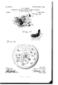
- Figure 1 is a front elevation of an automatic fire and burglar alarm instrument embodying the invention.
- Fig. 2 is a front elevation of the instrument with the cap or cover removed and showing the connections.
- Fig. 3 is a rear elevation.
- Fig. 4 is a bottom view.
- Fig. 5 is a top view.
- Fig. 6 is a detail view in perspective showing the means for controlling the locating-signals.
- Fig. 7 is an enlarged view in perspective of the means for producing a short circuit upon the breaking of any of the floor-section circuits.
- Fig. 8 is a vertical sectional view on line 8 8 of Fig.
- 1 denotes the back plate, of insulating material, which supports the mechanisms, including a bell 2, preferably secured to an extension 3 of the back plate.
- a train of gearing impelled by a coiled spring is mounted between frame-plates it 5, and to the escapement 6 of the train is secured the arm 7 of a bell-hammer 8.
- Secured also to the escapement is an arm 9, arranged to be normally engaged to lock the train by a trip 10 on an armature 11.
- a pair of magnets 12 I2, fixed to the back plate, have their pole-pieces 13 extended outwardly to normally attract the armature and lock the train, the armature being pivotally secured to a bracket let on one of the polepieces.
- the armature is arranged to fall by gravity to release the train when the magnets become deenergized, the limit of movement being fixed by a stop-screw 11.
- a central shaft 15 which preferably is driven directly by the mainspring of the gearing, is mounted an arm 16, carrying a handle 17, by which the spring wound, and provided at its free end with a pointer 18.
- an arm 16 Fixed to the shaft to the rear of the arm 16 is a plate 19, which in the rotation of the shaft is brought successively into engagement with a concentrieally-arranged series of contacts fixed to a curved support 20, of insulating material, the support being secured on the outer frame-plate
- Each of the contacts consists of two spring-arms 21 22, fixed at their inner ends in slots in the support and having their normally separated outer ends in the path of the plate 19, whereby the latter in its movement operates by engagement to press the ends of the arms into contact with each other, and thus produce a short circuit in the manner presently to be described.
- the contacts for the floor-signals are interposed between the initial or set position of the handle-arm 16 and the position thereof which indicates the exhaustion of the battery.
- the handle-arm In adjusting the instrument for service the handle-arm is turned to the set position and is, together with the train of gearing, locked by the trip 10 on the armature, the latter being attracted by the magnets.
- binding-screws On the back plate are binding-screws, certain of which are connected by wires with the contacts on the support 20.
- Awire 33 connects the binding-screw 24 to a binding-screw 34, to which is connected by a binding-post one end of the house or building circuit-wire 35.
- the other end of the house circuit-wire is connected by a binding-post with a screw 36, which is connected with one of the magnetwires 37
- Binding-posts, which are connected withthe binding-screws, are provided at the rear side of the back plate, and connected with the posts are the floor circuit-wires, which are shown in Fig. 2.
- the wire 39 of the firstfloor section leads from the screw to the section and back to the screw 25.
- the secondfioor-section wire 40 leads from the screw 25 to the section and back to the screw 30.
- the third-section wire 41 leads through the sec-
- the fourthsection wire 42 leads through the section and thence to the screw 32, and, finally, the fifthfioor-section wire 43 leads to the final springcontact 22.
- 38 is the other magnet-wire, which connects with the wire 43.
- circuit-wire 35 In the house circuit-wire 35 is a battery 44 and also a double-balanced relay 45, the function of which is to sound an alarm and announce disturbance occasioned by unlawful looping out or grounding of any of the floorsection wires or by weakening of the battery. Distinctive signals are provided in connection with the relay to announce whether the disturbance is due to an increased or diminished resistance in the circuit-wires.
- the plate 20 will traverse the contacts in advance of the pair connected with the disturbed section without closing the circuit; but when the contactsof the affected section are engaged'by the plate and brought together the circuit is established and the mechanism isstopped with the arm 16 at the point which indicates the locality of the disturbance.
- the length of the plate 19 is such as to extend between all of the contacts, whereby the engagement of the contacts is maintained throughout the entire movement of the plate. It the battery becomes exhausted, the circuit is broken and the arm moves to the position which indicates this character of disturbance.
- a dial-plate 46 is shown mounted in a removable cap or cover 47, the dial-plate having thereon in the path of the pointer 18 the floor-numbers, the set position of the arm, and the position of the arm when the battery has become exhausted.
- the instrument is connected with a main-line wire leading to the central office, in which line is located a tap-bell and recording instrument.
- the main-line wire 48 leads at one end to a binding-post connected with a binding-screw 49 on the back plate, and the other end of the wire leads to a binding-post connected with a binding-screw 50.
- a wire 51 connects the screw 49 with a screw 52 on the frame-plate 4, and a wire 53 connects the screw 50 with a spring-contact arm 54, fixed to a block 55 on the support 20, the block being of insulating material.
- the arm 54 is arranged between contact-arms 56 57, also fixed to the block 55 and having their outer ends bent in the direction ofthe middle arm 54.
- a shaft 58 On a shaft 58, which receives motion through the train of gearing, are fixed two make-andbreak wheels, one of which, 59, is notched in its periphery to send a building-signal, and the other, 60, is notched to transmit the floorsignal.
- a brush 62 Secured to a block 61 of insulating material is a brush 62 in contact with the wheel 59 and also a brush 63 in contact with the wheel 60;
- the brush 62 is connected by a wire 64 with the contact-arm 56, and a wire 65 connects the brush 63 with the contact-arm 57.
- the arms 54 and 56 are in contact, and a circuit is established with the main line to send when the mechanism is set in motion a building-signal by the wheel 59.
- the wheel 59 is provided with duplicate notches, and the wheel is geared tocomplete a revolution while the arm 16 is moving to the first pair of contacts 21 22, whereby two buildingsignals are sent to and recorded at the central office.
- the building-signals are followed by a signal which locatesthe flooi's of the building in which the disturbance is created, this being accomplished through the medium of the wheel in the following manner:
- a cam 66 On the shaft 15 is fixed a cam 66, which in the normal position of the parts is in the path of an insulated projection 67 on the middle contactarm 54, whereby the latter is forced against spring action out of contact with the arm 57, which connects with the floor-signal wheel, and into contact with the arm 56, which connects with the building-signal wheel.
- the instrument I may employ thermal circuit-breakers to produce the break necessary to send a fire-signal, and the floor-section wires and house-wires may be so arranged as to compel a break in the circuit before unlawful entry can be effected.
- the instrument may indicate the weakening and exhaustion of the battery and will announce through the relay an attempt to render the instrument inoperative by looping out, by which is meant the unlawful attachment of a wire looped around a floor-circuit wire to cut out the circuit.
Landscapes
- Business, Economics & Management (AREA)
- Emergency Management (AREA)
- Physics & Mathematics (AREA)
- General Physics & Mathematics (AREA)
- Fire Alarms (AREA)
Description
PATBNTED MAY 3, 1904.
R. G. GALLUM.
AUTOMATIC FIRE AND BURGLAB. ALARM TELEGRAPH.
APPLICATION FILED MAE. II 1902.
4 SHEETS-SHEET 1.
N0 MODEL.
PATENTED MAY 3, 1904.
R. G. GALLUM.
AUTOMATIC FIRE AND BURGLAR ALARM TELEGRAPH.
APPLIOATION FILED MAR. 1, 1902 4 SHEBTSSHEET 2.
NO MODEL.
FIE. E
v (inventor ,ffogerfaafi/m I 77/5 elf rbwm b wi lmmeo Noam puns cov r-normjrmo, WASPIIAQYUN n r No. 758,736. PATENTED MAY 3, 1904. R. G, CALLUM.
AUTOMATIC FIRE AND BURGLAR ALARM TELEGRAPH.
APPLIOATION FILED MAR. 1. 1902.
N0 MODEL. 4 SHEETS-SHEET a.
7 f9 P15; 57 fly" J 1/6 .55 w I f? 60 6/ 59 m 70 1J6 [f '0 ml'mv in 111 Ii? ml m r K v- IIIIIIIIIIIIIIHII lllllllllllllll Ill i f I ampcwtoc gigij/ooo co 20(56/"5 /Z 77 7309/0 M y 1 f k '5 fitter/@136 No. 758,786. PATENTED MAY 3, 1904. R. e. GALLUM.
AUTOMATIC FIRE AND BURGLAR ALARM TELEGRAPH.
APPLICATION FILED MAB. 1. 1902.
N0 MODEL. 4 SHEETBSHEET 4.
I 6 I: "5 I;
I I r- %1? 1 i FIE; E
UNITED ST TES Patented May 3, 1904.
ROBERT G. OALLUM, OF \VASI'IING'ITON, DISTRICT OF COLUMBIA.
AUTOMATIC FIRE AND BURGLAR ALARM TELEGRAPH.
SPECIFICATION forming part of Letters Pa n NO- 758,736, dated 3, 1904.
Application filed March 1, 1902.
To all whom, it 7')I/fl/ 7/ concern..-
Be it known that 1, ROBERT G. GALLUM, a citizen of the United States, residing at \Vashington, District of Columbia, have invented certain new and useful Improvements in Automatic Fire and Burglar Alarm TIelegraphs; and I do declare the following to be a full, clear, and exact description of the invention, such as willenable others skilled in the art to which it appertains to make and use the same, reference being had to the accompanying drawings, and to the figures of reference marked thereon, which form a part of this specification.
This invention, which relates to automatic fire and burglar alarm telegraph systems, contemplates the production of an etlicient and durable instrument combining in a compact structure improved means connecting a local or house wire, floor-section wires, and a mainline wire, all in normally closed metallic circuit with an annunciator, an alarm-bell, and a battery-signal, whereby any disturbance occasioned by fire or unlawful tampering with the wires or by exhaustion of the batteries is promptly made known to the occupants of the building affected and to the central office in a manner to announce to all concerned the exact locality and nature of such disturbance. The floor-sections are each connected by a metallic circuit with the instrument, and as another feature of the invention there is provided, preferably in the house-circuit, a relay which is operated coincidently with the unlawful looping out or grounding .of any of the floor-section circuits to sound a distinctive signal.
Other features of the invention, together with the advantages possessed thereby, are set forth in the following detailed description, in connection with which attention is called to the accompanying drawings, illustrating the preferred form of instrument and parts cooperating therewith.
In the drawings, Figure 1 is a front elevation of an automatic fire and burglar alarm instrument embodying the invention. Fig. 2 is a front elevation of the instrument with the cap or cover removed and showing the connections. Fig. 3 is a rear elevation. Fig.
Serial No. 96,223. \No model.)
4: is a bottom view. Fig. 5 is a top view. Fig. 6 is a detail view in perspective showing the means for controlling the locating-signals. Fig. 7 is an enlarged view in perspective of the means for producing a short circuit upon the breaking of any of the floor-section circuits. Fig. 8 is a vertical sectional view on line 8 8 of Fig.
Referring to the drawings by numerals, 1 denotes the back plate, of insulating material, which supports the mechanisms, including a bell 2, preferably secured to an extension 3 of the back plate. A train of gearing impelled by a coiled spring is mounted between frame-plates it 5, and to the escapement 6 of the train is secured the arm 7 of a bell-hammer 8. Secured also to the escapement is an arm 9, arranged to be normally engaged to lock the train by a trip 10 on an armature 11. A pair of magnets 12 I2, fixed to the back plate, have their pole-pieces 13 extended outwardly to normally attract the armature and lock the train, the armature being pivotally secured to a bracket let on one of the polepieces. The armature is arranged to fall by gravity to release the train when the magnets become deenergized, the limit of movement being fixed by a stop-screw 11.
On a central shaft 15, which preferably is driven directly by the mainspring of the gearing, is mounted an arm 16, carrying a handle 17, by which the spring wound, and provided at its free end with a pointer 18. Fixed to the shaft to the rear of the arm 16 is a plate 19, which in the rotation of the shaft is brought successively into engagement with a concentrieally-arranged series of contacts fixed to a curved support 20, of insulating material, the support being secured on the outer frame-plate Each of the contacts consists of two spring-arms 21 22, fixed at their inner ends in slots in the support and having their normally separated outer ends in the path of the plate 19, whereby the latter in its movement operates by engagement to press the ends of the arms into contact with each other, and thus produce a short circuit in the manner presently to be described.
By reference to Figs. 1 and 2 of the drawings it will be observed that the instrument tion and back to the screw 31.
is adjusted for use in a building having five floors, although obviously the number may be increased or diminished. The contacts for the floor-signals are interposed between the initial or set position of the handle-arm 16 and the position thereof which indicates the exhaustion of the battery. In adjusting the instrument for service the handle-arm is turned to the set position and is, together with the train of gearing, locked by the trip 10 on the armature, the latter being attracted by the magnets.
On the back plate are binding-screws, certain of which are connected by wires with the contacts on the support 20. The wire 23, which is connected with the first screw 24, leads to the arm 21 of the first pair of contacts, and leading from the second screw 25 is a wire 26, which connects with the arm 22 of the first pair of contacts and also with the arm 21 of the second pair, the first arm 22 and the second arm 21 being lapped at their.
inner ends, as shown more clearly in Fig. 7. ires 27, 28, and 29, respectively, lead from screws 30, 31, and 32 to the lapped arms 22 21 of the other contacts. Awire 33 connects the binding-screw 24 to a binding-screw 34, to which is connected by a binding-post one end of the house or building circuit-wire 35. The other end of the house circuit-wire is connected by a binding-post with a screw 36, which is connected with one of the magnetwires 37 Binding-posts, which are connected withthe binding-screws, are provided at the rear side of the back plate, and connected with the posts are the floor circuit-wires, which are shown in Fig. 2. The wire 39 of the firstfloor section leads from the screw to the section and back to the screw 25. The secondfioor-section wire 40 leads from the screw 25 to the section and back to the screw 30. The third-section wire 41 leads through the sec- The fourthsection wire 42 leads through the section and thence to the screw 32, and, finally, the fifthfioor-section wire 43 leads to the final springcontact 22. 38 is the other magnet-wire, which connects with the wire 43.
In the house circuit-wire 35 is a battery 44 and also a double-balanced relay 45, the function of which is to sound an alarm and announce disturbance occasioned by unlawful looping out or grounding of any of the floorsection wires or by weakening of the battery. Distinctive signals are provided in connection with the relay to announce whether the disturbance is due to an increased or diminished resistance in the circuit-wires.
When a break occurs in any of the normally closed floor-circuits, the magnets become deenergized and the armature falling by gravity unlocks the train of gearing, setting it in motion to revolve the handle-arm 16 and plate 19. As the plate engages the contactarms 21 22 the outer ends of the arms. are
moved against spring action into contact with each other to short-circuit the floor-section wire to which they are connected. This short circuit results in the energizing of the magnet, whereby the armature is attracted and moved to lock the train and the handlearm. Obviously if the break occurs in the upper floor-sections the plate 20 will traverse the contacts in advance of the pair connected with the disturbed section without closing the circuit; but when the contactsof the affected section are engaged'by the plate and brought together the circuit is established and the mechanism isstopped with the arm 16 at the point which indicates the locality of the disturbance. The length of the plate 19 is such as to extend between all of the contacts, whereby the engagement of the contacts is maintained throughout the entire movement of the plate. It the battery becomes exhausted, the circuit is broken and the arm moves to the position which indicates this character of disturbance.
Referring to Figs. 1 and 4, a dial-plate 46 is shown mounted in a removable cap or cover 47, the dial-plate having thereon in the path of the pointer 18 the floor-numbers, the set position of the arm, and the position of the arm when the battery has become exhausted. The instrument is connected with a main-line wire leading to the central office, in which line is located a tap-bell and recording instrument. The main-line wire 48 leads at one end to a binding-post connected with a binding-screw 49 on the back plate, and the other end of the wire leads to a binding-post connected with a binding-screw 50. A wire 51 connects the screw 49 with a screw 52 on the frame-plate 4, and a wire 53 connects the screw 50 with a spring-contact arm 54, fixed to a block 55 on the support 20, the block being of insulating material. The arm 54 is arranged between contact-arms 56 57, also fixed to the block 55 and having their outer ends bent in the direction ofthe middle arm 54.
On a shaft 58, which receives motion through the train of gearing, are fixed two make-andbreak wheels, one of which, 59, is notched in its periphery to send a building-signal, and the other, 60, is notched to transmit the floorsignal. Secured to a block 61 of insulating material is a brush 62 in contact with the wheel 59 and also a brush 63 in contact with the wheel 60; The brush 62 is connected by a wire 64 with the contact-arm 56, and a wire 65 connects the brush 63 with the contact-arm 57. Normally the arms 54 and 56 are in contact, and a circuit is established with the main line to send when the mechanism is set in motion a building-signal by the wheel 59. The wheel 59 is provided with duplicate notches, and the wheel is geared tocomplete a revolution while the arm 16 is moving to the first pair of contacts 21 22, whereby two buildingsignals are sent to and recorded at the central office. The building-signals are followed by a signal which locatesthe flooi's of the building in which the disturbance is created, this being accomplished through the medium of the wheel in the following manner: On the shaft 15 is fixed a cam 66, which in the normal position of the parts is in the path of an insulated projection 67 on the middle contactarm 54, whereby the latter is forced against spring action out of contact with the arm 57, which connects with the floor-signal wheel, and into contact with the arm 56, which connects with the building-signal wheel. In the initial movement of the parts the contact of the arms 54 56 is maintained by the cam a sufficient length of time to permit the duplicate building-signal to be sent in; but in the final movement the cam is carried out of the path of the projection 67, and the arm 54 is thereby retracted and disengaged from the arm 56 and brought into contact with the arm 57 to send in, through the wheel 60, the floorsignal.
In connection with the instrument I may employ thermal circuit-breakers to produce the break necessary to send a fire-signal, and the floor-section wires and house-wires may be so arranged as to compel a break in the circuit before unlawful entry can be effected. Coincident with the alarm given to the occupants of the affected building, which alarm in eludes an indication of the location of trouble, the fact of such disturbance and the exact 10- cality of the building are announced to the cen tral oflice. The instrument, moreover, will indicate the weakening and exhaustion of the battery and will announce through the relay an attempt to render the instrument inoperative by looping out, by which is meant the unlawful attachment of a wire looped around a floor-circuit wire to cut out the circuit.
In practice in the event of a break in the circuit-wire 39 of floor 1, for instance, the magnets 12 12 become deenergized and the armature 11, falling by gravity, effects the release of the clockwork, with the result of rotating the plate 19 until the latter is brought into engagement with the first spring-contact 21. This engagement closes the break between said contact 21 and its companion contact 22, and through wires 23, 35, and 3'7 and the wires 26, floor-section wires 40 to 43, inclusive, and wire 38 the circuit through the magnets is established and the armature is attracted and moved to check the clockwork, the pointer stopping at 1st floor. In the operation of the released works the circuit in wire 48 is broken by the separation of the contacts 54 56 and the making of the circuit in which is located the make-and-break wheels 59 60 by the engagements of the contacts 54 57.
I claim as my invention 1. In an instrument of the class described, the combination of normally closed electric floor-section circuits, a house-circuit connected therewith, a magnet, a spring-actuated train of gearing, an armature normally attracted by said magnet and provided with means normally locking the train of gearing, a circular series of pairs of spring-contacts each pair looped from a floor-section circuit, and a revoluble plate operatively connected with said train to be moved thereby when any one of the floor-section circuits is broken, said plate being movable over the series of pairs of spring-contacts to successively bring the pairs of contacts into maintained engagement to short-circuit the floor-section circuits.
2. In an instrument of the class described, the combination of normally closed electric floor-section circuits, a house-circuit including a double-balanced relay, a normally open circuit looped in the floor-section circuits, an annunciator, a device for successively closing said loops, and maintaining them in closed condition, and means for actuating the annunciator and device adapted to be set in motion by the breaking of one of the floor-section circuits.
3. In an instrument of the class described, the combination of a normally closed electric floor-section circuit, a normally open circuit looped therein, a train of gearing, a device movable by the train when the floor-section circuit is broken to close the loop and maintain a closed circuit, a main-line circuit, and building and floor signal making wheels in the main-line circuit said wheels being successively controlled by the movement of the device.
4. In an instrument of the class described, the combination of a local normally closed electric circuit, means operating through a train of gearing when the circuit is broken for producing and maintaining a short circuit, a main-line circuit, and building and floor signal making wheels in the main-line circuit the wheels being successively controlled by the movement of said means.
In testimony whereof I affix my signature in presence of two witnesses.
ROBERT Gr. CALLUM.
WVitnesses:
J. WV. TAYLOR, M. G. ANDERSON.
Priority Applications (1)
| Application Number | Priority Date | Filing Date | Title |
|---|---|---|---|
| US9622302A US758736A (en) | 1902-03-01 | 1902-03-01 | Automatic fire and burglar alarm telegraph. |
Applications Claiming Priority (1)
| Application Number | Priority Date | Filing Date | Title |
|---|---|---|---|
| US9622302A US758736A (en) | 1902-03-01 | 1902-03-01 | Automatic fire and burglar alarm telegraph. |
Publications (1)
| Publication Number | Publication Date |
|---|---|
| US758736A true US758736A (en) | 1904-05-03 |
Family
ID=2827226
Family Applications (1)
| Application Number | Title | Priority Date | Filing Date |
|---|---|---|---|
| US9622302A Expired - Lifetime US758736A (en) | 1902-03-01 | 1902-03-01 | Automatic fire and burglar alarm telegraph. |
Country Status (1)
| Country | Link |
|---|---|
| US (1) | US758736A (en) |
-
1902
- 1902-03-01 US US9622302A patent/US758736A/en not_active Expired - Lifetime
Similar Documents
| Publication | Publication Date | Title |
|---|---|---|
| US758736A (en) | Automatic fire and burglar alarm telegraph. | |
| US460464A (en) | Automatic electric fire-alarm system | |
| US395958A (en) | dewey | |
| US478789A (en) | denio | |
| US773869A (en) | Automatic electrical signaling system. | |
| US405831A (en) | dewey | |
| US653469A (en) | Electric signaling apparatus. | |
| US368809A (en) | Combined electric receiving and transmitting device | |
| US421530A (en) | Island | |
| US392766A (en) | Ments | |
| US695991A (en) | Electric signaling and circuit-controlling apparatus. | |
| US505819A (en) | downs | |
| US424860A (en) | Automatic fire-alarm | |
| US362739A (en) | g-heqan | |
| US706384A (en) | Fire-alarm-telegraph system. | |
| US395111A (en) | Fire-alarm annunciator | |
| US641950A (en) | Electric fire-alarm system. | |
| US481847A (en) | Fire-alarm telegraph | |
| US607343A (en) | conway | |
| US365726A (en) | Electric circuit-testing apparatus | |
| US769409A (en) | Electric signaling system. | |
| US358393A (en) | John h | |
| US594034A (en) | price | |
| US883539A (en) | Annunciator. | |
| US172221A (en) | Improvement in double-acting fire and burglar alarm telegraphs |