US7573379B2 - Mobile, retractile, lateral deploying, vehicle disablement device - Google Patents
Mobile, retractile, lateral deploying, vehicle disablement device Download PDFInfo
- Publication number
- US7573379B2 US7573379B2 US11/606,618 US60661806A US7573379B2 US 7573379 B2 US7573379 B2 US 7573379B2 US 60661806 A US60661806 A US 60661806A US 7573379 B2 US7573379 B2 US 7573379B2
- Authority
- US
- United States
- Prior art keywords
- retractile
- inner tube
- mobile
- providing
- spring
- Prior art date
- Legal status (The legal status is an assumption and is not a legal conclusion. Google has not performed a legal analysis and makes no representation as to the accuracy of the status listed.)
- Active, expires
Links
Images


Classifications
-
- E—FIXED CONSTRUCTIONS
- E01—CONSTRUCTION OF ROADS, RAILWAYS, OR BRIDGES
- E01F—ADDITIONAL WORK, SUCH AS EQUIPPING ROADS OR THE CONSTRUCTION OF PLATFORMS, HELICOPTER LANDING STAGES, SIGNS, SNOW FENCES, OR THE LIKE
- E01F13/00—Arrangements for obstructing or restricting traffic, e.g. gates, barricades ; Preventing passage of vehicles of selected category or dimensions
- E01F13/12—Arrangements for obstructing or restricting traffic, e.g. gates, barricades ; Preventing passage of vehicles of selected category or dimensions for forcibly arresting or disabling vehicles, e.g. spiked mats
-
- Y—GENERAL TAGGING OF NEW TECHNOLOGICAL DEVELOPMENTS; GENERAL TAGGING OF CROSS-SECTIONAL TECHNOLOGIES SPANNING OVER SEVERAL SECTIONS OF THE IPC; TECHNICAL SUBJECTS COVERED BY FORMER USPC CROSS-REFERENCE ART COLLECTIONS [XRACs] AND DIGESTS
- Y10—TECHNICAL SUBJECTS COVERED BY FORMER USPC
- Y10T—TECHNICAL SUBJECTS COVERED BY FORMER US CLASSIFICATION
- Y10T137/00—Fluid handling
- Y10T137/6851—With casing, support, protector or static constructional installations
- Y10T137/6855—Vehicle
- Y10T137/6914—Vehicle supports fluid compressor and compressed fluid storage tank
Definitions
- the present invention relates to vehicle disablement and, more particularly, to a device that is mobile and retractile.
- U.S. Pat. No. 5,820,293 in which a device is thrown, by hand, across the roadway into the path of an oncoming pursued vehicle in order to deflate the tires.
- U.S. Pat. No. 5,775,832 describes a device that is used in the same manner as the previously listed device but differs in that the device itself is wider upon deployment and has a different type of spike.
- U.S. Pat. No. 6,623,205 describes a mobile device which when deployed is said to disable vehicle tires.
- U.S. Pat. No. 5,839,849 describes a device meant to be used from within a police vehicle at speed.
- Devices described on television programs and magazines have included electronic remote controlled vehicles, which are said to have the ability to shut down a vehicle's computer, thus disabling said vehicle when remote controlled vehicle is driven under vehicle pursued.
- Scientific magazines have suggested that electromagnetic pulse may be used in the future.
- U.S. Pat. No. 5,820,293 describes a device in which the police must know where the fleeing suspect is going and get there ahead of them, get out of the car and deploy said device across the roadway by hand.
- Kilgrew U.S. Pat. No. 5,775,832 describes a device which must be deployed by hand across the roadway.
- U.S. Pat. No. 6,527,475 describes a device that necessitates police pulling in front of the pursued vehicle to deploy the device. Police are unwilling to do this, given the possibility that the suspect may have a weapon. Being in front of a suspect with a weapon is too dangerous for the police to even consider this course of action.
- the tethering of the described device provides for rapid deceleration of said device and therefore must be timed perfectly in order to be effective.
- the best possible use of the aforementioned device is its use when the police car is not moving.
- a device which upon activation, disables a fleeing vehicle from within the safety of the operator's vehicle.
- the device mounts directly to the operator's vehicle.
- This device is controlled by the operator from within the vehicle by way of a control panel mounted within reach of either the driver or passenger of said vehicle.
- the system is armed using a protected switch mounted on said panel. This sends power to the momentary deployment switch and allows for instant deployment upon activation of said momentary deployment switch.
- the momentary deployment switch is activated, allowing air from the air reservoir to flow through the solenoid valve and air hose to pressurize the telescoping assembly and thereby extend the piston and inner tube outward to their limiting stops.
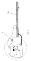
- FIG. 1 is a front perspective view of a mobile, retractile, lateral deploying, vehicle disablement device, in retracted position, mounted to vehicle;
- FIG. 2 is a front perspective view of a mobile, retractile, lateral deploying, vehicle disablement device, in deployed position, mounted to vehicle;
- FIG. 3 is a front view of a mobile, retractile, lateral deploying, vehicle disablement device, with electrical and pneumatic systems attached;
- FIG. 4 is a front view of an electrical and pneumatic systems
- FIG. 5 is a front view of a mobile, retractile, lateral deploying, vehicle disablement device in the retracted position
- FIG. 6 is a top view of a mobile, retractile, lateral deploying, vehicle disablement device in retracted position
- FIG. 7 is a front view of a mobile, retractile, lateral deploying, vehicle disablement device in deployed position
- FIG. 8 is a top view of a mobile, retractile, lateral deploying, vehicle disablement device in deployed position
- FIG. 9 is a front view of a mobile, retractile, lateral deploying, vehicle disablement device in retracted position
- FIG. 10 is a top view of a mobile, retractile, lateral deploying, vehicle disablement device in retracted postion;
- FIG. 11 is a front sectional detail view of a mobile, retractile, lateral deploying, vehicle disablement device in retracted position
- FIG. 12 is a front sectional detail view of a mobile, retractile, lateral deploying, vehicle disablement device in retracted position
- FIG. 13 is a left detail view of an outer tube spring housing 430 ;
- FIG. 14 is a front detail view of an outer tube spring housing 430 ;
- FIG. 15 is a right detail view of an outer tube spring housing 430 ;
- FIG. 16 is a top detail view of an outer tube spring housing 430 ;
- FIG. 17 is a left detail view of an inner tube spring housing 440 ;
- FIG. 18 is a front detail view of an inner tube spring housing 440 ;
- FIG. 19 is a right detail view of an inner tube spring housing 440 .
- FIG. 20 is a top detail view of an inner tube spring housing 440 .
- FIG. 1 is a front perspective view of a mobile, retractile, lateral deploying, vehicle disablement device, in retracted position, mounted to vehicle.
- FIG. 2 is a front perspective view of a mobile, retractile, lateral deploying, vehicle disablement device, in deployed position, mounted to vehicle.
- FIG. 3 is a front view of a mobile, retractile, lateral deploying, vehicle disablement device, with electrical and pneumatic systems attached.
- Telescoping assembly 510 may be constructed of metal, plastic, or any suitable material forming a square, rectangle or any suitable shape when viewed from either end. Telescoping assembly 510 consists of all the elements listed except for the electrical and pneumatic systems. Telescoping assembly 510 is connected to the electrical and pneumatic systems using magnetic switch cable 232 and pneumatic air hose 224 .
- FIG. 4 is a front view of an electrical and pneumatic system.
- Air hose 224 is a flexible, rubber-like hose or other suitable material. Air hose 224 is coupled to solenoid valve 213 by conventional means. Exhaust muffler 214 prevents debris and insects from entering the exhaust port of solenoid valve 213 . Exhaust muffler 214 can be made of metal, plastic or other suitable material. Exhaust muffler 214 is connected to solenoid valve 213 by conventional means. Solenoid valve 213 is a three way type electrically operated pneumatic control valve or suitable replacement. Solenoid valve 213 is coupled to air reservoir 211 by conventional means. Solenoid valve 213 is electrically connected to electrical control enclosure 226 with electrical wiring. Air reservoir 211 is made of metal, fiberglass or other suitable material.
- Air reservoir 211 is connected to pneumatic compressor 210 using flexible, rigid or any suitable means of compressed air transfer.
- Pressure switch 212 is an air pressure operated switch that has a set of electrical contacts for controlling the pneumatic compressor 210 .
- Pressure switch 212 is coupled to air reservoir 211 by conventional means.
- Pressure switch 212 is electrically connected to the electrical control enclosure 226 using standard electrical wiring.
- Pneumatic compressor 210 is an electric motor driven compressor or other suitable style.
- Pneumatic compressor 210 is electrically connected to electrical control enclosure 226 using standard electrical wiring.
- Electrical control enclosure 226 houses all wiring connections between the electrical components.
- Electrical control enclosure 226 is electrically connected to dash controls enclosure 237 using panel cable 233 .
- Switch 238 is electrically connected to panel cable 233 and mounted to dash controls enclosure 237 using conventional means.
- Arming switch 238 is of the safety type with a safety snap cover to prevent unwanted operation of the switch. Arming switch 238 is electrically connected to dash cable and mounted to dash controls enclosure 237 .
- Momentary deployment pushbutton 240 is electrically connected to dash cable and mounted to dash controls enclosure 237 using conventional means.
- Deployed indicator light 239 is electrically connected to dash cable and is mounted to dash controls enclosure 237 using conventional means.
- Maintained deployment switch 241 is electrically connected to dash cable and is mounted to dash controls enclosure 237 using conventional means.
- Dash controls enclosure 237 provides a housing for the dash area control switches used by the operator and is made of metal, plastic or other suitable material. Dash controls enclosure 237 is mounted to the dash area or any other appropriate area within reach of operator using conventional means.
- FIG. 5 is a front view of a mobile, retractile, lateral deploying, vehicle disablement device in the retracted position.
- This figure also shows the reference to the section view of FIG. 10 .
- FIG. 6 is a top view of a mobile, retractile, lateral deploying, vehicle disablement device in deployed position.
- This figure also shows the reference to the section view of FIG. 9 .
- FIG. 7 is a front view of a mobile, retractile, lateral deploying, vehicle disablement device in retracted position.
- Pivot spring assembly 322 is fabricated from spring material and metal or other suitable materials. Pivot spring assembly 322 is shown in extended position to denote its placement in reference to the outermost end of the inner tube 411 .
- FIG. 8 is a top view of a mobile, retractile, lateral deploying, vehicle disablement device in deployed position.
- FIG. 9 is a front view of a mobile, retractile, lateral deploying, vehicle disablement device in retracted position.
- This figure also shows the reference to detailed views of FIG. 11 and FIG. 12 .
- FIG. 10 is a top view of a mobile, retractile, lateral deploying, vehicle disablement device in retracted position.
- FIG. 11 is an enlarged front sectional view of a mobile, retractile, lateral deploying, vehicle disablement device in retracted position.
- Outer tube 410 is fabricated from metal, plastic or other suitable material and is square, rectangle or other suitable shaped tubing.
- Inner tube 411 is fabricated from metal, plastic, or other suitable material and is the same shape as outer tube 410 .
- Inner tube 411 is smaller in size than outer tube 410 allowing it to be inserted inside outer tube 410 .
- Air hose 224 is connected to threaded hole on bottom of outer tube 410 by conventional means allowing for movement of compressed air from solenoid valve 213 to telescoping assembly 510 .
- Air hose 224 is attached to threaded hole on bottom of outer tube 410 using a quick release coupling for convenience but is not required or limited to this means of connection.
- Pop off valve 471 is a pressure relieving device that prevents excessive pressure within telescoping assembly 510 and is attached to threaded hole on bottom of outer tube 410 by conventional means.
- Outer tube spring housing 430 is fabricated from metal, plastic or other suitable material. Outer tube spring housing 430 is inserted into outer tube 410 and is sealed and fastened using conventional means.
- Large spring drum axles 437 are female threaded metal or other suitable material. Large spring drum axles 437 are mounted within outer tube spring housing 430 using conventional fasteners.
- Large spring drums 436 are fabricated from plastic or other suitable material and provide a wheel-like action for the large constant force springs 432 to coil and uncoil upon. Large spring drums 436 are mounted and rotate upon large spring drum axles 437 .
- Large constant force springs 432 are coiled around the circumference of large spring drums 436 and attached to large constant force springs end mount 450 using conventional means.
- Large constant force springs end mount 450 is fabricated from metal, plastic or other suitable material.
- Outer tube spring housing bumpers 453 are made of a rubber-like material and fastened with a threaded stud or other suitable means. Outer tube spring housing bumpers 453 are attached to outer tube spring housing 430 using conventional means.
- Large constant force springs end mount 450 is fabricated using metal, plastic or other suitable materials.
- Large constant force springs end mount 450 is fastened to inner tube spring housing 440 using conventional means.
- Inner tube seal 452 is made of rubber-like, plastic or other suitable material and fits the shape of the inside walls of the outer tube 410 .
- Inner tube seal 452 is sandwiched between large constant force springs end mount 450 and inner tube spring housing 440 and is held in place by the compression force of the fasteners which attach large constant force springs end mount 450 to inner tube spring housing 440 .
- Inner tube plastic bearing plates 415 are fabricated from sheet plastic or other suitable low friction material and are slightly thinner than the clearance between outer tube 410 and inner tube 411 .
- Inner tube plastic bearing plates 415 are fastened to the outside surfaces at the innermost end of inner tube 411 .
- Inner tube plastic bearing plates 415 provide a low friction surface for the innermost end of inner tube 411 to slide within outer tube 410 .
- Inner tube stop plates 413 are fabricated from sheet metal or other suitable high strength material.
- Inner tube stop plates 413 are fastened to the outside surfaces of the inner tube 411 adjacent to inner tube plastic bearing plates 415 .
- Inner tube spring housing 440 is fabricated from metal, plastic or other suitable material and houses the small constant force springs 442 with their associated small spring drums 445 and small spring drum axles 446 .
- Inner tube spring housing 440 also provides a mount for inner tube spring housing bumper 451 .
- Inner tube spring housing 440 is inserted into inner tube 411 and is sealed and fastened using conventional means.
- Small spring drum axles 446 are female threaded metal or other suitable material and are mounted within inner tube spring housing 440 using conventional fasteners.
- Small spring drums 445 are fabricated from plastic or other suitable material and provide a wheel-like action for the small constant force springs 442 to coil and uncoil upon. Small spring drums 445 are mounted and rotate upon small spring drum axles 446 . Small constant force springs 442 are coiled around the circumference of small spring drums 445 . Small constant force springs end mount 456 is fabricated from metal, plastic, or other suitable and fastened to inner most end of piston 454 using conventional means. Piston seal 455 is made of rubber-like, plastic or other suitable material and fits the shape of the inside walls of the inner tube 411 and is sandwiched between small constant force springs end mount 456 and piston 454 .
- Piston seal 455 is held in place by the compression force of the fasteners which attach small constant force springs end mount 456 to piston 454 .
- Magnet 458 is of the high force permanent type or other suitable style and is mounted within a recess of the piston 454 using friction, adhesives or other suitable means. This recess is deep enough to prevent the magnet 458 from rubbing inner tube 411 .
- Magnetic switch 466 is of the reed type switch that is activated by the presence of a magnetic force in the immediate area. Magnetic switch 466 senses the magnet 458 that is mounted within piston 454 . Magnetic switch 466 is mounted to the exterior of outer tube 410 using welds, adhesives or other suitable means of attachment.
- Piston 454 is fabricated from plastic or other suitable low friction material and provides a sturdy mount for pivot spring assembly female mounting tube 459 . Piston 454 is inserted inside of inner tube 411 and travels between inner tube spring housing bumper 451 and piston end stops 461 . Pivot spring assembly female mounting tube 459 is fabricated from metal pipe, metal bar stock or other suitable high strength material. Pivot spring assembly female mounting tube 459 is inserted inside of a drilled or machined hole in the outermost end of piston 454 and is fastened using conventional means.
- Pivot spring assembly female mounting tube 459 provides a sturdy female opening for pivot spring assembly 322 to be inserted within and held in place by pivot spring release pin 326 .
- Pivot spring assembly 322 is fabricated from metal and an extension spring, or other suitable materials. The extension spring is welded or fastened to the other components forming the pivot spring assembly 322 . This creates a flexible and sacrificial mount for the spike strip 320 .
- Spike strip 320 is fabricated from metal, plastic or other suitable flexible materials and is attached to the outermost end of pivot spring assembly 322 using conventional means.
- Tire spikes 321 are fabricated from metal or other suitable high strength material. Tire spikes 321 are of the needle type, broadhead arrow type or other type suitable for being inserted into a tire and deflating it. Tire spikes 321 are inserted into holes in spike strip 320 and held in place by friction, adhesives or other suitable means. Tire spikes 321 are intended to penetrate the tire and be removed from spike strip 320 and stay lodged in tire.
- FIG. 12 is an enlarged front sectional view of a mobile, retractile, lateral deploying, vehicle disablement device in retracted position.
- Outer tube anti slide brackets 472 are fabricated from metal, plastic or other suitable material and are attached to outside bottom of outer tube 410 using conventional means. Outer tube anti slide brackets 472 prevent telescoping assembly 510 from sliding in vehicle mounting brackets.
- Stop plate bumpers 421 are fabricated from rubber-like sheets or other suitable material and are housed between the outer sides of inner tube 411 and inner sides of outer tube 410 . Stop plate bumpers 421 are thinner than the space between inner tube 411 and outer tube 410 allowing stop plate bumpers 421 to float freely between inner tube stop plates 413 and outer tube stop plates 412 . Stop plate bumpers 421 provide a cushion between inner tube stop plates 413 and outer tube stop plates 412 when inner tube 411 reaches outer most end of extension.
- Outer tube stop plates 412 are fabricated from sheet metal or other suitable high strength material and are fastened to inside surfaces of outer tube 410 adjacent to outer tube plastic bearing plates 414 using conventional means.
- Outer tube plastic bearing plates 414 are fabricated from plastic sheet or other suitable low friction material and are fastened to inside surfaces of outer most end of outer tube 410 .
- Outer tube plastic bearing plates 414 are slightly thinner than clearance between outer tube 410 and inner tube 411 .
- Outer tube plastic bearing plates 414 provide a low friction surface for inner tube 411 to slide within outer tube 410 .
- Piston end stops 461 are fabricated from metal or other suitable high strength material and are fastened to two opposite inside surfaces at outer most end of inner tube 411 by conventional means. Piston end stops 461 also serve the function of limiting the travel of spike strip 320 upward within inner tube 411 .
- FIG. 13 is a left detail view of the outer tube spring housing 430 .
- FIG. 14 is a front detail view of the outer tube spring housing 430 .
- FIG. 15 is a right detail view of the outer tube spring housing 430 .
- Outer tube spring housing 430 is fabricated from metal, plastic or other suitable material and is shown as a welded metal assembly. However the outer tube spring housing 430 can be glued or machined if suitable.
- FIG. 16 is a top detail view of the outer tube spring housing 430 .
- Outer tube spring housing 430 is fabricated from metal, plastic or other suitable material and is shown as a welded metal assembly. However the outer tube spring housing 430 can be glued or machined if suitable.
- FIG. 17 is a left detail view of the inner tube spring housing 440 .
- FIG. 18 is a front detail view of the inner tube spring housing 440 .
- FIG. 19 is a right detail view of the inner tube spring housing 440 .
- FIG. 20 is a top detail view of the inner tube spring housing 440 .
- Inner tube spring housing 440 is fabricated from metal, plastic or other suitable material and is shown as a welded metal assembly. However the inner tube spring housing 440 can be glued or machined if suitable.
Landscapes
- Engineering & Computer Science (AREA)
- Architecture (AREA)
- Civil Engineering (AREA)
- Structural Engineering (AREA)
- Vehicle Body Suspensions (AREA)
Abstract
Description
Claims (92)
Priority Applications (2)
| Application Number | Priority Date | Filing Date | Title |
|---|---|---|---|
| US11/606,618 US7573379B2 (en) | 2006-11-29 | 2006-11-29 | Mobile, retractile, lateral deploying, vehicle disablement device |
| US12/496,543 US8154396B2 (en) | 2005-12-01 | 2009-07-01 | Vehicle disablement device |
Applications Claiming Priority (1)
| Application Number | Priority Date | Filing Date | Title |
|---|---|---|---|
| US11/606,618 US7573379B2 (en) | 2006-11-29 | 2006-11-29 | Mobile, retractile, lateral deploying, vehicle disablement device |
Related Child Applications (1)
| Application Number | Title | Priority Date | Filing Date |
|---|---|---|---|
| US12/496,543 Continuation-In-Part US8154396B2 (en) | 2005-12-01 | 2009-07-01 | Vehicle disablement device |
Publications (2)
| Publication Number | Publication Date |
|---|---|
| US20080124171A1 US20080124171A1 (en) | 2008-05-29 |
| US7573379B2 true US7573379B2 (en) | 2009-08-11 |
Family
ID=39463878
Family Applications (1)
| Application Number | Title | Priority Date | Filing Date |
|---|---|---|---|
| US11/606,618 Active 2027-10-30 US7573379B2 (en) | 2005-12-01 | 2006-11-29 | Mobile, retractile, lateral deploying, vehicle disablement device |
Country Status (1)
| Country | Link |
|---|---|
| US (1) | US7573379B2 (en) |
Cited By (13)
| Publication number | Priority date | Publication date | Assignee | Title |
|---|---|---|---|---|
| US20090263191A1 (en) * | 2005-12-01 | 2009-10-22 | Moormeier Michael P | Vehicle disablement device |
| US20100086349A1 (en) * | 2008-10-06 | 2010-04-08 | Martinez Martin A | Apparatus and method for disabling a ground engaging traction device of a land vehicle |
| US20100196092A1 (en) * | 2008-09-29 | 2010-08-05 | Pacific Scientific Energetic Materials Company | Apparatuses, systems and methods for selectively affecting movement of a motor vehicle |
| US20100221066A1 (en) * | 2008-10-06 | 2010-09-02 | Martinez Martin A | Apparatus and method for disabling a ground engaging traction device of a land vehicle |
| US20110229260A1 (en) * | 2010-03-17 | 2011-09-22 | Scott Robert L | Wireless Tire Deflation Device Launcher |
| CN102720151A (en) * | 2012-05-22 | 2012-10-10 | 王光树 | Rear interception device for motor vehicle |
| US8469627B2 (en) | 2008-09-29 | 2013-06-25 | Pacific Scientific Energetic Materials Company (Arizona), Llc | Apparatuses, systems and methods for selectively affecting movement of a motor vehicle |
| US8517625B2 (en) | 2008-10-06 | 2013-08-27 | Pacific Scientific Energetic Materials Company (Arizona), Llc | Apparatus and method for disabling a ground engaging traction device of a land vehicle |
| US20140209011A1 (en) * | 2013-01-28 | 2014-07-31 | Electronics & Telecommunications Research Institute | Safety tripod apparatus for vehicle |
| US8858113B1 (en) | 2014-01-23 | 2014-10-14 | Leonard Jon Bettendorf | Tire deflation device for puncturing one or more tires of a fleeing vehicle |
| US9103082B2 (en) | 2008-10-06 | 2015-08-11 | Pacific Scientific Energetic Materials Company (Arizona) LLC | Apparatus and method for rapidly deflating tires to disable a land vehicle |
| CN106340196A (en) * | 2015-07-10 | 2017-01-18 | 罗伯特·博世有限公司 | System And Method For Selecting And Stopping A Vehicle Using Vehicle-To-Vehicle Communication |
| US10301786B2 (en) | 2015-03-23 | 2019-05-28 | Pacific Scientific Energetic Materials Company (California) LLC | Deployable device having an unrolled configuration for rapid, bi-directional immobilization of a targeted vehicle traveling on a roadway, and associated methods |
Families Citing this family (6)
| Publication number | Priority date | Publication date | Assignee | Title |
|---|---|---|---|---|
| AU2008207606A1 (en) * | 2007-08-31 | 2009-03-19 | Michael Schubert | Portable Road Barrier Unit |
| US8132980B1 (en) | 2009-12-16 | 2012-03-13 | Lee Justin D | Spike strip system and method for deploying said system from a vehicle |
| EP2648564A2 (en) * | 2010-12-07 | 2013-10-16 | Csir | Transportation of valuables |
| US8506203B2 (en) | 2011-03-23 | 2013-08-13 | Dynasystems, LLC | Tire deflation device |
| CN110485330B (en) * | 2019-08-19 | 2024-05-24 | 中国人民武装警察部队特种警察学院 | Portable car stopping device |
| US20230349115A1 (en) * | 2021-05-18 | 2023-11-02 | Mitchell Joel Bendix | Extendable Air Deployment Tire Deflation System |
Citations (8)
| Publication number | Priority date | Publication date | Assignee | Title |
|---|---|---|---|---|
| US5406251A (en) * | 1993-03-23 | 1995-04-11 | Leis; Kenneth | Air operated pivoting safety apparatus for vehicle |
| US5611408A (en) * | 1995-04-07 | 1997-03-18 | Abukhader; Saleem A. | Vehicle disabling device |
| US5890832A (en) * | 1995-09-29 | 1999-04-06 | Eagle Research Group, Inc. | Method and apparatus for deflating a tire of a vehicle |
| US6758628B1 (en) * | 2002-11-01 | 2004-07-06 | Joseph Edward Curry, Jr. | Method and apparatus for deflating tires of a trailing vehicle |
| US6869248B1 (en) * | 2003-12-12 | 2005-03-22 | Dustin C. Threlkeld | Disabling system for use with law enforcement vehicle |
| US7108446B2 (en) * | 2004-03-09 | 2006-09-19 | Clark Brent A | Emergency warning device rapid deployment system |
| US7275889B1 (en) * | 2006-06-09 | 2007-10-02 | Mcgill David T | Targeted tethered tire capture projectile |
| US20080159809A1 (en) * | 2006-04-07 | 2008-07-03 | Costa James M | Method and system for stopping a vehicle |
-
2006
- 2006-11-29 US US11/606,618 patent/US7573379B2/en active Active
Patent Citations (8)
| Publication number | Priority date | Publication date | Assignee | Title |
|---|---|---|---|---|
| US5406251A (en) * | 1993-03-23 | 1995-04-11 | Leis; Kenneth | Air operated pivoting safety apparatus for vehicle |
| US5611408A (en) * | 1995-04-07 | 1997-03-18 | Abukhader; Saleem A. | Vehicle disabling device |
| US5890832A (en) * | 1995-09-29 | 1999-04-06 | Eagle Research Group, Inc. | Method and apparatus for deflating a tire of a vehicle |
| US6758628B1 (en) * | 2002-11-01 | 2004-07-06 | Joseph Edward Curry, Jr. | Method and apparatus for deflating tires of a trailing vehicle |
| US6869248B1 (en) * | 2003-12-12 | 2005-03-22 | Dustin C. Threlkeld | Disabling system for use with law enforcement vehicle |
| US7108446B2 (en) * | 2004-03-09 | 2006-09-19 | Clark Brent A | Emergency warning device rapid deployment system |
| US20080159809A1 (en) * | 2006-04-07 | 2008-07-03 | Costa James M | Method and system for stopping a vehicle |
| US7275889B1 (en) * | 2006-06-09 | 2007-10-02 | Mcgill David T | Targeted tethered tire capture projectile |
Cited By (25)
| Publication number | Priority date | Publication date | Assignee | Title |
|---|---|---|---|---|
| US20090263191A1 (en) * | 2005-12-01 | 2009-10-22 | Moormeier Michael P | Vehicle disablement device |
| US8154396B2 (en) * | 2005-12-01 | 2012-04-10 | Pursuit Management, Inc. | Vehicle disablement device |
| US8186905B2 (en) | 2008-09-29 | 2012-05-29 | Pacific Scientific Energetic Material Company (Arizona), LLC | Apparatuses, systems and methods for selectively affecting movement of a motor vehicle |
| US9702100B2 (en) | 2008-09-29 | 2017-07-11 | Pacific Scientific Energetic Materials Company | Apparatuses, systems and methods for selectively affecting movement of a motor vehicle |
| US20100196092A1 (en) * | 2008-09-29 | 2010-08-05 | Pacific Scientific Energetic Materials Company | Apparatuses, systems and methods for selectively affecting movement of a motor vehicle |
| US8911172B2 (en) | 2008-09-29 | 2014-12-16 | Pacific Scientific Energetic Materials Company | Apparatuses, systems and methods for selectively affecting movement of a motor vehicle |
| US8905672B2 (en) | 2008-09-29 | 2014-12-09 | Pacific Scientific Energetic Materials Company (Arizona) LLC | Apparatuses, systems and methods for selectively affecting movement of a motor vehicle |
| US8596904B2 (en) | 2008-09-29 | 2013-12-03 | Pacific Scientific Energetic Materials Company (Arizona), Llc | Apparatuses, systems and methods for selectively affecting movement of a motor vehicle |
| US8469627B2 (en) | 2008-09-29 | 2013-06-25 | Pacific Scientific Energetic Materials Company (Arizona), Llc | Apparatuses, systems and methods for selectively affecting movement of a motor vehicle |
| US8517625B2 (en) | 2008-10-06 | 2013-08-27 | Pacific Scientific Energetic Materials Company (Arizona), Llc | Apparatus and method for disabling a ground engaging traction device of a land vehicle |
| US9340935B2 (en) | 2008-10-06 | 2016-05-17 | Pacific Scientific Energetic Materials Company (Arizona) LLC | Apparatus and method for rapidly deflating tires to disable a land vehicle |
| US9714492B2 (en) | 2008-10-06 | 2017-07-25 | Pacific Scientific Energetic Materials Company (Arizona) LLC | Apparatus and method for rapidly deflating tires to disable a land vehicle |
| US8066446B2 (en) | 2008-10-06 | 2011-11-29 | Pacific Scientific Energetic Materials Company | Apparatus and method for disabling a ground engaging traction device of a land vehicle |
| US20100086349A1 (en) * | 2008-10-06 | 2010-04-08 | Martinez Martin A | Apparatus and method for disabling a ground engaging traction device of a land vehicle |
| US9103082B2 (en) | 2008-10-06 | 2015-08-11 | Pacific Scientific Energetic Materials Company (Arizona) LLC | Apparatus and method for rapidly deflating tires to disable a land vehicle |
| US20100221066A1 (en) * | 2008-10-06 | 2010-09-02 | Martinez Martin A | Apparatus and method for disabling a ground engaging traction device of a land vehicle |
| US7997825B2 (en) * | 2008-10-06 | 2011-08-16 | Pacific Scientific Energetic Materials Corporation | Apparatus and method for disabling a ground engaging traction device of a land vehicle |
| US20110229260A1 (en) * | 2010-03-17 | 2011-09-22 | Scott Robert L | Wireless Tire Deflation Device Launcher |
| US8087847B2 (en) * | 2010-03-17 | 2012-01-03 | Scott Robert L | Wireless tire deflation device launcher |
| CN102720151A (en) * | 2012-05-22 | 2012-10-10 | 王光树 | Rear interception device for motor vehicle |
| US20140209011A1 (en) * | 2013-01-28 | 2014-07-31 | Electronics & Telecommunications Research Institute | Safety tripod apparatus for vehicle |
| US8858113B1 (en) | 2014-01-23 | 2014-10-14 | Leonard Jon Bettendorf | Tire deflation device for puncturing one or more tires of a fleeing vehicle |
| US10301786B2 (en) | 2015-03-23 | 2019-05-28 | Pacific Scientific Energetic Materials Company (California) LLC | Deployable device having an unrolled configuration for rapid, bi-directional immobilization of a targeted vehicle traveling on a roadway, and associated methods |
| CN106340196A (en) * | 2015-07-10 | 2017-01-18 | 罗伯特·博世有限公司 | System And Method For Selecting And Stopping A Vehicle Using Vehicle-To-Vehicle Communication |
| CN106340196B (en) * | 2015-07-10 | 2020-08-11 | 罗伯特·博世有限公司 | Method for selecting and stopping a vehicle using vehicle-to-vehicle communication |
Also Published As
| Publication number | Publication date |
|---|---|
| US20080124171A1 (en) | 2008-05-29 |
Similar Documents
| Publication | Publication Date | Title |
|---|---|---|
| US7573379B2 (en) | Mobile, retractile, lateral deploying, vehicle disablement device | |
| US7201531B2 (en) | Vehicle skidstop | |
| US20110198161A1 (en) | Master braking system and method therefor | |
| EP0900158B1 (en) | Method and device for forced stopping of a vehicle | |
| US20170210284A1 (en) | Vehicle-mounted retractable illuminated emergency alert system | |
| US8132980B1 (en) | Spike strip system and method for deploying said system from a vehicle | |
| US8154396B2 (en) | Vehicle disablement device | |
| US7591477B2 (en) | System for capturing a vehicle | |
| KR102649589B1 (en) | vehicle safety barrier | |
| WO1999026808A1 (en) | Safety system and device, as well as safety enhancing process appropriate therefor | |
| CN105835811B (en) | Vehicle and its vehicle safety mechanism and means of defence | |
| CN107531179B (en) | Vehicle emergency safety device using self-help rod | |
| US20090231155A1 (en) | Emergency/hazard warning system | |
| US9940816B2 (en) | Parking brake warning system for air brakes | |
| US9434226B1 (en) | Vehicle control system | |
| KR101984818B1 (en) | Emergency signal apparatus for a vehicle | |
| US20120024221A1 (en) | Signal and marker tool | |
| RU2274566C1 (en) | Emergency brake | |
| US20230064569A1 (en) | Vehicle Chock System | |
| WO2009049106A2 (en) | Signal and marker tool | |
| KR20030012947A (en) | Auxiliary braking system for iced road | |
| US9132795B1 (en) | Vehicle bumper apparatus and system for PIT maneuvers | |
| US20230349115A1 (en) | Extendable Air Deployment Tire Deflation System | |
| KR200268573Y1 (en) | Auxiliary braking system for iced road | |
| US20060147319A1 (en) | Anti-door jam (ADJ) |
Legal Events
| Date | Code | Title | Description |
|---|---|---|---|
| AS | Assignment |
Owner name: PURSUIT MANAGEMENT, INC., NEVADA Free format text: ASSIGNMENT OF ASSIGNORS INTEREST;ASSIGNORS:MOORMEIER, MICHAEL PATRICK;O'HALLORAN, TODD CORY;REEL/FRAME:022450/0809 Effective date: 20090314 |
|
| AS | Assignment |
Owner name: PURSUIT MANAGEMENT, INC., NEVADA Free format text: CORRECTIVE ASSIGNMENT TO CORRECT THE IDENTIFICATION OF THE ASSIGNEES PREVIOUSLY RECORDED ON REEL 022450 FRAME 0809;ASSIGNORS:MOORMEIER, MICHAEL PATRICK;O'HALLORAN, TODD CORY;REEL/FRAME:022509/0590 Effective date: 20090314 Owner name: MOORMEIER, MICHAEL PATRICK, WASHINGTON Free format text: CORRECTIVE ASSIGNMENT TO CORRECT THE IDENTIFICATION OF THE ASSIGNEES PREVIOUSLY RECORDED ON REEL 022450 FRAME 0809;ASSIGNORS:MOORMEIER, MICHAEL PATRICK;O'HALLORAN, TODD CORY;REEL/FRAME:022509/0590 Effective date: 20090314 Owner name: O'HALLORAN, TODD CORY, OREGON Free format text: CORRECTIVE ASSIGNMENT TO CORRECT THE IDENTIFICATION OF THE ASSIGNEES PREVIOUSLY RECORDED ON REEL 022450 FRAME 0809;ASSIGNORS:MOORMEIER, MICHAEL PATRICK;O'HALLORAN, TODD CORY;REEL/FRAME:022509/0590 Effective date: 20090314 |
|
| STCF | Information on status: patent grant |
Free format text: PATENTED CASE |
|
| FPAY | Fee payment |
Year of fee payment: 4 |
|
| FPAY | Fee payment |
Year of fee payment: 8 |
|
| AS | Assignment |
Owner name: MOBILESPIKE, INC., WASHINGTON Free format text: MERGER;ASSIGNOR:MOBILESPIKE TECHNOLOGIES, INC.;REEL/FRAME:042009/0218 Effective date: 20160507 Owner name: MOBILESPIKE TECHNOLOGIES INC., NEVADA Free format text: CHANGE OF NAME;ASSIGNOR:PURSUIT MANAGEMENT, INC.;REEL/FRAME:042257/0325 Effective date: 20160204 |
|
| MAFP | Maintenance fee payment |
Free format text: PAYMENT OF MAINTENANCE FEE, 12TH YR, SMALL ENTITY (ORIGINAL EVENT CODE: M2553); ENTITY STATUS OF PATENT OWNER: SMALL ENTITY Year of fee payment: 12 |