US7539377B2 - Method and device for optically coupling optical fibres - Google Patents

Method and device for optically coupling optical fibres Download PDF

Info

Publication number
US7539377B2
US7539377B2 US11/976,476 US97647607A US7539377B2 US 7539377 B2 US7539377 B2 US 7539377B2 US 97647607 A US97647607 A US 97647607A US 7539377 B2 US7539377 B2 US 7539377B2
Authority
US
United States
Prior art keywords
coupler
optical
fiber
coupling
optical fiber
Prior art date
Legal status (The legal status is an assumption and is not a legal conclusion. Google has not performed a legal analysis and makes no representation as to the accuracy of the status listed.)
Expired - Fee Related
Application number
US11/976,476
Other versions
US20080170823A1 (en
Inventor
François Gonthier
Current Assignee (The listed assignees may be inaccurate. Google has not performed a legal analysis and makes no representation or warranty as to the accuracy of the list.)
9180-8030 QUEBEC Inc
Original Assignee
Individual
Priority date (The priority date is an assumption and is not a legal conclusion. Google has not performed a legal analysis and makes no representation as to the accuracy of the date listed.)
Filing date
Publication date
Application filed by Individual filed Critical Individual
Priority to US11/976,476 priority Critical patent/US7539377B2/en
Publication of US20080170823A1 publication Critical patent/US20080170823A1/en
Application granted granted Critical
Publication of US7539377B2 publication Critical patent/US7539377B2/en
Assigned to 9180-8030 QUEBEC INC. reassignment 9180-8030 QUEBEC INC. ASSIGNMENT OF ASSIGNORS INTEREST (SEE DOCUMENT FOR DETAILS). Assignors: GONTHIER, FRANCOIS
Assigned to 9180-8030 QUEBEC INC. reassignment 9180-8030 QUEBEC INC. CORRECTIVE ASSIGNMENT TO CORRECT THE POSTAL CODE IN THE ADDRESS OF THE ASSIGNOR FROM G1S 2P8 TO G1S 1P8 PREVIOUSLY RECORDED ON REEL 027063 FRAME 0471. ASSIGNOR(S) HEREBY CONFIRMS THE ASSIGNMENT. Assignors: GONTHIER, FRANCOIS
Expired - Fee Related legal-status Critical Current
Anticipated expiration legal-status Critical

Links

Images

Classifications

    • GPHYSICS
    • G02OPTICS
    • G02BOPTICAL ELEMENTS, SYSTEMS OR APPARATUS
    • G02B6/00Light guides; Structural details of arrangements comprising light guides and other optical elements, e.g. couplings
    • G02B6/24Coupling light guides
    • G02B6/26Optical coupling means
    • G02B6/28Optical coupling means having data bus means, i.e. plural waveguides interconnected and providing an inherently bidirectional system by mixing and splitting signals
    • G02B6/2804Optical coupling means having data bus means, i.e. plural waveguides interconnected and providing an inherently bidirectional system by mixing and splitting signals forming multipart couplers without wavelength selective elements, e.g. "T" couplers, star couplers
    • GPHYSICS
    • G02OPTICS
    • G02BOPTICAL ELEMENTS, SYSTEMS OR APPARATUS
    • G02B6/00Light guides; Structural details of arrangements comprising light guides and other optical elements, e.g. couplings
    • G02B6/02Optical fibres with cladding with or without a coating
    • G02B6/02295Microstructured optical fibre
    • G02B6/02314Plurality of longitudinal structures extending along optical fibre axis, e.g. holes
    • G02B6/02342Plurality of longitudinal structures extending along optical fibre axis, e.g. holes characterised by cladding features, i.e. light confining region
    • G02B6/02376Longitudinal variation along fibre axis direction, e.g. tapered holes
    • GPHYSICS
    • G02OPTICS
    • G02BOPTICAL ELEMENTS, SYSTEMS OR APPARATUS
    • G02B6/00Light guides; Structural details of arrangements comprising light guides and other optical elements, e.g. couplings
    • G02B6/24Coupling light guides
    • G02B6/26Optical coupling means
    • G02B6/28Optical coupling means having data bus means, i.e. plural waveguides interconnected and providing an inherently bidirectional system by mixing and splitting signals
    • G02B6/2804Optical coupling means having data bus means, i.e. plural waveguides interconnected and providing an inherently bidirectional system by mixing and splitting signals forming multipart couplers without wavelength selective elements, e.g. "T" couplers, star couplers
    • G02B6/2808Optical coupling means having data bus means, i.e. plural waveguides interconnected and providing an inherently bidirectional system by mixing and splitting signals forming multipart couplers without wavelength selective elements, e.g. "T" couplers, star couplers using a mixing element which evenly distributes an input signal over a number of outputs
    • GPHYSICS
    • G02OPTICS
    • G02BOPTICAL ELEMENTS, SYSTEMS OR APPARATUS
    • G02B6/00Light guides; Structural details of arrangements comprising light guides and other optical elements, e.g. couplings
    • G02B6/24Coupling light guides
    • G02B6/26Optical coupling means
    • G02B6/28Optical coupling means having data bus means, i.e. plural waveguides interconnected and providing an inherently bidirectional system by mixing and splitting signals
    • G02B6/2804Optical coupling means having data bus means, i.e. plural waveguides interconnected and providing an inherently bidirectional system by mixing and splitting signals forming multipart couplers without wavelength selective elements, e.g. "T" couplers, star couplers
    • G02B6/2817Optical coupling means having data bus means, i.e. plural waveguides interconnected and providing an inherently bidirectional system by mixing and splitting signals forming multipart couplers without wavelength selective elements, e.g. "T" couplers, star couplers using reflective elements to split or combine optical signals
    • GPHYSICS
    • G02OPTICS
    • G02BOPTICAL ELEMENTS, SYSTEMS OR APPARATUS
    • G02B6/00Light guides; Structural details of arrangements comprising light guides and other optical elements, e.g. couplings
    • G02B6/24Coupling light guides
    • G02B6/26Optical coupling means
    • G02B6/28Optical coupling means having data bus means, i.e. plural waveguides interconnected and providing an inherently bidirectional system by mixing and splitting signals
    • G02B6/2804Optical coupling means having data bus means, i.e. plural waveguides interconnected and providing an inherently bidirectional system by mixing and splitting signals forming multipart couplers without wavelength selective elements, e.g. "T" couplers, star couplers
    • G02B6/2821Optical coupling means having data bus means, i.e. plural waveguides interconnected and providing an inherently bidirectional system by mixing and splitting signals forming multipart couplers without wavelength selective elements, e.g. "T" couplers, star couplers using lateral coupling between contiguous fibres to split or combine optical signals
    • HELECTRICITY
    • H01ELECTRIC ELEMENTS
    • H01SDEVICES USING THE PROCESS OF LIGHT AMPLIFICATION BY STIMULATED EMISSION OF RADIATION [LASER] TO AMPLIFY OR GENERATE LIGHT; DEVICES USING STIMULATED EMISSION OF ELECTROMAGNETIC RADIATION IN WAVE RANGES OTHER THAN OPTICAL
    • H01S3/00Lasers, i.e. devices using stimulated emission of electromagnetic radiation in the infrared, visible or ultraviolet wave range
    • H01S3/09Processes or apparatus for excitation, e.g. pumping
    • H01S3/091Processes or apparatus for excitation, e.g. pumping using optical pumping
    • H01S3/094Processes or apparatus for excitation, e.g. pumping using optical pumping by coherent light
    • H01S3/094003Processes or apparatus for excitation, e.g. pumping using optical pumping by coherent light the pumped medium being a fibre
    • HELECTRICITY
    • H01ELECTRIC ELEMENTS
    • H01SDEVICES USING THE PROCESS OF LIGHT AMPLIFICATION BY STIMULATED EMISSION OF RADIATION [LASER] TO AMPLIFY OR GENERATE LIGHT; DEVICES USING STIMULATED EMISSION OF ELECTROMAGNETIC RADIATION IN WAVE RANGES OTHER THAN OPTICAL
    • H01S3/00Lasers, i.e. devices using stimulated emission of electromagnetic radiation in the infrared, visible or ultraviolet wave range
    • H01S3/09Processes or apparatus for excitation, e.g. pumping
    • H01S3/091Processes or apparatus for excitation, e.g. pumping using optical pumping
    • H01S3/094Processes or apparatus for excitation, e.g. pumping using optical pumping by coherent light
    • H01S3/094049Guiding of the pump light
    • H01S3/094053Fibre coupled pump, e.g. delivering pump light using a fibre or a fibre bundle

Definitions

  • the present invention relates to the general field of optical fibers, and is particularly concerned with methods and devices for optically coupling optical fibers.
  • a signal fiber carries a signal and is optically pumped using laser light having another wavelength to amplify the signal.
  • the laser light coming from the pump fibers is carried into the signal fiber and thereby provides the power required to amplify the signal circulating in, the signal fiber.
  • optical fibers are stripped of their sheath and heated while positioned substantially adjacent to each other until the pump fibers are fused and optically coupled to the signal fiber. This involves deforming the pump fibers until they achieve a shape suitable for optically coupling to the signal fiber.
  • coupling the pump fiber typically occurs by deforming to a relatively large extend the pump fiber around the periphery of the cladding of the signal fiber. This creates surface tension problems that result in power losses. Since it is desirable, in many instances, to pump relatively large power into the signal fiber, these power losses may heat the optical fibers and eventually lead to failure of the optical amplifier. In addition, these methods for manufacturing optical amplifiers and other devices in which optical fibers are optically coupled to each other are relatively difficult to perform and it is relatively difficult to achieve reproducible results using these methods.
  • Another manner of optically coupling pump fibers to a signal fiber involves the use of a signal fiber having a relatively large diameter. Then, the pumped fibers may be axially coupled to the cladding of the signal fiber which is then deformed to achieve a shape suitable for guiding the light carried by the pump fibers into the core of the signal fiber.
  • these methods for manufacturing optical fibers are relatively complex to implement. Also, they may lead to the creation of stresses within the coupled assemblies, as there is typically a need to handle the optical fibers and attach them to supports for packaging purposes.
  • An object of the present invention is therefore to provide such methods and devices for optically coupling optical fibers.
  • the invention provides an optical coupler, the optical coupler being usable with a first optical fiber and a second optical fiber.
  • the second optical fiber defines a second fiber coupling section and a second fiber transmitting section extending from the second fiber coupling section.
  • the second fiber coupling section defines a radially outwardmost peripheral surface, the radially outwardmost peripheral surface defining a peripheral surface coupling portion.
  • the optical coupler includes a coupler first end section and a substantially opposed coupler second end section, the coupler first end section defining a first coupling surface.
  • the optical coupler defines a second coupling surface extending along the coupler first and second end sections.
  • the first coupling surface is optically couplable with the first optical fiber and the second coupling surface is positionable so as to extend substantially parallel to the peripheral surface coupling portion and to be optically coupled with the peripheral surface coupling portion.
  • the optical coupler has optical and geometrical properties such that substantially all the light guided to the first coupling surface by the first optical fiber is directed towards the second coupling surface and into the second optical fiber through the peripheral surface coupling portion so as to be guided into the second fiber coupling section for transmission into the second fiber transmitting portion.
  • the invention provides a method for assembling an optical coupling assembly for optically coupling a first and a second optical fiber using an optical coupler, the second optical fiber defining a second fiber coupling section and a second fiber transmitting section extending from the second fiber coupling section, the second fiber coupling section defining a radially outwardmost peripheral surface, the radially outwardmost peripheral surface defining a peripheral surface coupling portion, the optical coupler including a coupler first end section and a substantially opposed coupler second end section, the coupler first end section defining a first coupling surface, the optical fiber defining a second coupling surface extending along the coupler first and second end sections.
  • the method includes: positioning the first optical fiber substantially adjacent to the first coupling surface; optically coupling the first optical fiber and the first coupling surface to each other; positioning the second optical fiber such that the second coupling surface is substantially adjacent and substantially parallel to the peripheral surface coupling portion; and optically coupling the second coupling surface and the peripheral surface coupling portion to each other.
  • the invention provides a method for assembling an optical coupling assembly for optically coupling a first, a second and a third optical fiber using an optical coupler, the first, second, and third optical fiber each defining respectively a first, a second and a third fiber free end, the optical coupler including a coupler first end section and a substantially opposed coupler second end section, the coupler first end section defining a first coupling surface, the optical coupler defining a coupler passageway extending along the first and second end sections.
  • the method includes: positioning the first optical fiber free end substantially adjacent to the first coupling surface; optically coupling the first optical fiber and the first coupling surface to each other; inserting the second optical fiber, at least partially, into the coupler passageway; optically coupling the optical coupler and the second optical fiber into the coupler passageway; positioning the third fiber free end substantially adjacent to the second fiber free end; and optically coupling the second and third fiber free ends to each other.
  • the invention provides an optical coupling assembly, the optical coupling assembly including a first optical fiber, a second optical fiber, the second optical fiber defining a second fiber coupling section and a second fiber transmitting section extending from the second fiber coupling section, the second fiber coupling section defining a radially outwardmost peripheral surface, the radially outwardmost peripheral surface defining a peripheral surface coupling portion and an optical coupler.
  • the optical coupler defines a coupler first end section and a substantially opposed coupler second end section, the coupler first end section defining a first coupling surface, the first optical fiber being optically coupled with the first coupling surface.
  • a second coupling surface extends between the coupler first and second end sections, the second coupling surface being substantially parallel to the peripheral surface coupling portion and optically coupled thereto.
  • the optical coupler has optical and geometrical properties such that substantially all the light guided to the first coupling surface by the first optical fiber is directed towards the second coupling surface and into the second optical fiber through the peripheral surface coupling portion so as to be guided into the second fiber coupling section for transmission into the second fiber transmitting portion.
  • the optical coupler allows to relatively easily assemble together the optical coupler and the first and second optical fibers. Furthermore, the optical coupler and optical fibers assembly is relatively robust and relatively efficient in transmitting power between the first optical fiber and the second optical fiber.
  • the proposed optical coupler allows to relatively easily optimize relationships between the cross-sectional area over which the light propagating in the first and second optical fibers and the numerical apertures of the first and second optical fibers so as to optimize power transmission between the first optical fiber and the second optical fiber.
  • optical coupler resides in the possibility to optically couple to many types of optical fiber that are often difficult to couple to conventionally, such as for example monomode fibers, polarisation-maintaining fibers and microstructured fibers, among other possibilities.
  • the present invention has also an advantage that it facilitates the coupling of optical fibers that are heat sensitive as the second optical fiber may be glued to the optical coupler. Furthermore, since the first optical fiber may be fused with the optical coupler before inserting the second optical fiber, the second optical fiber can also be heat sensitive and nevertheless be used with the proposed optical coupler according to the invention.
  • FIG. 1 in a perspective view, illustrates an optical coupler in accordance with an embodiment of the present invention optically coupled to two optical fibers;
  • FIG. 2 in a rear plan view, illustrates the optical coupler shown in FIG. 1 ;
  • FIG. 3 in a side cross-sectional view, illustrates the optical coupler shown in FIGS. 1 and 2 ;
  • FIG. 4 in a side cross-sectional view, illustrates an optical coupler in accordance with an alternative embodiment of the present invention optically coupled to two optical fibers;
  • FIG. 5 in a perspective view, illustrates an optical coupler in accordance with another alternative embodiment of the invention optically coupled to three optical fibers;
  • FIG. 6 in a side cross-sectional view, illustrates the optical coupler shown in FIG. 5 coupled to three optical fiber in a first manner
  • FIG. 7 in a side cross-sectional view, illustrates the optical coupler shown in FIGS. 5 and 6 coupled to three optical fiber in a second manner
  • FIG. 8A in a side cross-sectional view, illustrates an optical coupler in accordance with yet another alternative embodiment of the present invention optically coupled to two optical fibers;
  • FIG. 8B in a side cross-sectional view, illustrates an optical coupler in accordance with yet another alternative embodiment of the present invention optically coupled to two optical fibers;
  • FIG. 9 in a rear elevation view, illustrates the optical coupler shown in FIG. 8 ;
  • FIG. 10 in a perspective view, illustrates an optical coupler in accordance with yet another embodiment of the invention optically coupled to two optical fibers
  • FIG. 11 in a rear plan view, illustrates the optical coupler shown in FIG. 10 ;
  • FIG. 12 in a side cross-sectional view with parts removed, illustrates the optical coupler shown in FIGS. 10 and 11 ;
  • FIG. 13 in a perspective view, illustrates an optical coupler in accordance with yet another embodiment of the present invention optically coupled to one optical fiber;
  • FIG. 14 in a rear plan view, illustrates the optical coupler shown in FIG. 13 ;
  • FIG. 15 in a side elevation view, illustrates the optical coupler shown in FIGS. 13 and 14 ;
  • FIG. 16 in a side elevation view, illustrates an optical coupler in accordance with yet another embodiment of the present invention optically coupled to one optical fiber;
  • FIG. 17 in a rear plan view, illustrates the optical coupler shown in FIG. 16 ;
  • FIG. 18 in a side elevation view, illustrates an optical coupler in accordance with yet another embodiment of the present invention optically coupled to one optical fiber;
  • FIG. 19 in a rear plan view, illustrates the optical coupler shown in FIG. 18 ;
  • FIG. 20 in a side cross-sectional view, illustrates the optical coupler shown in FIGS. 1 to 3 optically coupled to two optical fibers, one of which is optically coupled outside of the optical coupler to a third optical fiber;
  • FIG. 21 in a side cross-sectional view, illustrates the optical coupler shown in FIGS. 1 to 3 optically coupled to two optical fibers, one of which is optically coupled at the end of the optical coupler to a third optical fiber;
  • FIG. 22 in a side cross-sectional view, illustrates the optical coupler shown in FIGS. 1 to 3 optically coupled to two optical fibers, one of which is optically coupled inside of the optical coupler to a third optical fiber;
  • FIG. 23 in perspective view, illustrates the optical coupler shown in FIGS. 1 to 3 optically coupled to five optical fibers, one of which is glued to the optical coupler inside a coupler passageway extending longitudinally through the optical coupler;
  • FIG. 24 in a side cross-sectional view, illustrates the optical coupler shown in FIG. 23 ;
  • FIG. 25 in a rear elevation, illustrates an optical coupler in accordance with yet another embodiment of the present invention, one of which is part of a fiber bundle inserted through a coupler passageway of the optical coupler;
  • FIG. 26A in a perspective view, illustrates a first step in a method for manufacturing an optical coupler in accordance with yet another embodiment of the present invention
  • FIG. 26B in a perspective view, illustrates a second step in the method for manufacturing an optical coupler illustrated in FIG. 26A ;
  • FIG. 26C in a perspective view, illustrates a third step in the method for manufacturing an optical coupler illustrated in FIGS. 26A and 26B .
  • FIGS. 1 to 3 illustrate an optical coupler 10 in accordance with an embodiment of the present invention.
  • the optical coupler 10 is usable for optically coupling a first optical fiber 12 to a second optical fiber 16 .
  • more than one optical fiber 12 are optically coupled to the second optical fiber 16 .
  • these other optical fibers take the form of a bundle of optical fibers 13 .
  • the optical coupler 10 is manufacturable such that it includes a surface for coupling to the second optical fiber 16 in a substantially radial direction. The surface is formed so as to have a shape that substantially conforms to the outer surface of the second optical fiber 16 .
  • the optical coupler 10 is configured and has optical properties such that essentially all the light incoming at the first optical fiber 12 is guided into the second optical fiber 16 . Typically, this is achieved by adiabatically tapering the optical coupler 10 into the second optical fiber 16 substantially opposite to the first optical fiber 12 . To that effect, the optical coupler 10 is configured so as to be substantially tangential to the second optical fiber at a location wherein the optical coupler 10 ceases to contact the optical fiber 16 . This results in the optical coupler 10 coupling the light incoming at the first optical fiber 12 , and at the other optical fibers of the bundle of optical fibers 13 , to the cladding of the second optical fiber 16 .
  • the optical coupling between the first optical fiber 12 and the second optical fiber 16 is a multimode coupling.
  • the first optical fiber 12 , and the other optical fibers 12 of the bundle of optical fibers 13 are multimode fibers.
  • the second optical fiber 16 is a multimode optical fiber, a multiple core optical fiber, a double-clad optical fiber, a single-mode optical fiber or any other suitable optical fiber.
  • the first optical fiber 12 defines a first fiber free end 14 . It should be understood that the first fiber free end 14 is here shown attached to the optical coupler 10 . The term “free end” therefore applies to the configuration of the first optical fiber 12 before it is coupled to the optical coupler 10 .
  • the first optical fiber 12 includes a first fiber core and a first fiber cladding extending substantially radially outwardly from the first fiber core.
  • the second optical fiber 16 defines a second fiber free end 18 .
  • the second optical fiber 16 includes a second fiber core 24 and a second fiber cladding 26 extending substantially radially outwardly from the second fiber core 24 .
  • the second fiber core and cladding 24 and 26 are both substantially cylindrical. For clarity reasons, the second fiber core and cladding 24 and 26 are not distinguishly shown in the other Figures of the present application.
  • the second optical fiber 16 defines a second fiber coupling section 20 and a second fiber transmitting section 22 extending from the second fiber coupling section 20 .
  • the second fiber coupling section 20 defines a radially outwardmost peripheral surface 28 .
  • the radially outwardmost peripheral surface 28 is typically defined by the second fiber cladding 26 .
  • the radially outwardmost peripheral surface 28 defines a peripheral surface coupling portion 30 .
  • the peripheral surface coupling portion 30 is a portion of the radially outwardmost peripheral surface 28 through which light coming from the first optical fiber 12 , or from other similarly located optical fibers, enters into the second optical fiber 16 .
  • the peripheral surface coupling portion 30 and the radially outwardmost peripheral surface 28 are substantially the same as light may enter the second optical fiber 16 from any direction.
  • the optical coupler 10 defines a coupler first end section 36 and a substantially opposed coupler second end section 38 .
  • the coupler first end section 36 defines a first coupling surface 40 .
  • the optical coupler 10 defines a second coupling surface 42 extending along the coupler first and second end sections 36 and 38 .
  • the coupler second end section 38 extend substantially longitudinally from the coupler first end section 36 .
  • the coupler first and second end sections 36 and 38 are not adjacent to each other.
  • the first optical fiber 12 is optically coupled with the first coupling surface 40 .
  • the peripheral surface coupling portion 30 is positionable so as to extend substantially parallel to the second coupling surface 42 and is optically coupled with the second coupling surface 42 .
  • the optical coupler 10 has optical and geometrical properties such that substantially all the light guided to the first coupling surface 40 by the first optical fiber 12 is directed towards the second coupling surface 42 and into the second optical fiber 16 through the peripheral surface coupling portion 30 so as to be guided into the second fiber coupling section 20 for transmission into the second fiber transmitting section 22 .
  • an optical coupler 10 that includes a tapered section 44 tapering in a direction leading from the coupler first end section 36 towards the coupler second end section 38 .
  • the tapered section 44 is located substantially distally relatively to the first fiber free end 14 and extends substantially longitudinally from the coupler first end section 36 .
  • the coupler first end section 36 is substantially cylindrical and the coupler second end section 38 is substantially frusto-conical and therefore forms the tapered section 44 .
  • the rotational symmetry of these configurations facilitates manufacturing of the optical coupler 10 and the attachment of many optical fibers to the first coupling surface 40 .
  • the optical coupler 10 defines a coupler passageway 46 extending along the coupler first and second end sections 36 and 38 . More specifically, the coupler passageway 46 extends between the ends of the optical coupler 10 .
  • the second coupling surface 42 is located substantially peripherally relatively to the coupler passageway 46 . In other words, the internal surface of the optical coupler 10 defining the coupler passageway 46 is, in this embodiment of the invention, the second coupling surface 42 .
  • the second coupling surface 42 is therefore substantially cylindrical. This configuration allows to have many optical fibers similar to the first optical fiber 12 attached to the optical coupler 10 such that the light incoming for all these optical fibers is guidable into the second optical fiber 16 .
  • the coupler passageway 46 is radially substantially centrally located relatively to the coupler first end section 36 .
  • many other suitable shapes exist for the optical coupler 10 .
  • the peripheral surface coupling portion 30 is optically coupled to the second coupling surface 42 by a coupling medium 60 located between the second coupling surface 42 and the peripheral surface coupling portion 30 .
  • a coupling medium 60 is ethanol or any other suitable transparent liquid.
  • Another example of such a coupling medium 60 is a bonding material.
  • the coupling medium 60 has a refraction index substantially similar to the refraction index of the second fiber cladding 26 (not seen in FIG. 24 ).
  • the optical coupler 10 has also the same refraction index as the second fiber cladding 26 (not seen in FIG. 24 ).
  • the second coupling surface 42 and the peripheral surface coupling portion 30 are fused to each other.
  • the diameter of the coupler first end section 36 is selected as a function of the diameters and numerical apertures of the first and second optical fibers 12 and 16 such that optimal coupling between the first and second optical fibers 12 and 16 occurs.
  • a cylindrical tube of 800 ⁇ m external diameter and 405 ⁇ m internal diameter is used.
  • the tube is cut to the length of 2 cm.
  • the tube is then etched or polished to obtain a conical shape over 1 cm at one end as per FIGS. 1-3 to complete manufacturing of the optical coupler 10 .
  • At the cylindrical end, forming the coupler first end section 36 up to 9 200-micron core fibers (numerical aperture (NA) of 0.22) can be fused to the first coupling surface 40 .
  • a second 20/400 ⁇ m double clad fiber is stripped and cleaved and the ends of the last two fibers are aligned to transmit light. This alignment is optimized and the fibers are spliced using a heat source.
  • the heat source is than gradually scanned towards the conical part of the optical coupler 10 , which thus collapses on the internal fiber, thus creating a coupling between the tube and the inner fiber.
  • This enable light guided from the multimode optical fiber to be coupled into the double-clad fiber with only a few percent loss. The thus obtain optical structure is then packaged for protection.
  • Another embodiment of this invention is obtained by following than same procedure as above but use a 340 ⁇ m external diameter tube with a 130 internal diameter. Then, 6 105 ⁇ m core fibers with 0.15 NA can be spliced to the tube and a 125 ⁇ m cladding diameter double-clad fiber can be inserted into the coupler passageway 46 and coupled thereto after fusioning the various parts. This assembly thereby formed is also relatively low loss.
  • the first optical fiber 12 is substantially longitudinally coupled to the first coupling surface 40 .
  • the first coupling surface 40 is substantially perpendicular to the first optical fiber 12 .
  • the first coupling surface 40 is also substantially perpendicular to the second coupling surface 42 .
  • the optical coupler 10 is provided separately from the first and second optical fibers 12 and 16 . Then, the first optical fiber 12 is positioned substantially adjacent to the first coupling surface 40 . Afterwards, the first optical fiber 12 is optically coupled to the first coupling surface 40 . For example, this is performed by splicing the first optical fiber with the first coupling surface. Afterwards, the second optical fiber 16 is positioned such that the second coupling surface 42 is substantially adjacent and substantially parallel to the peripheral surface coupling portion 30 . Then, the second coupling surface 42 and the peripheral surface coupling portion 30 are optically coupled to each other.
  • the second coupling surface 42 and the peripheral surface coupling portion 30 are optically coupled to each other by fusing the second coupling surface 42 and the peripheral surface coupling portion 30 to each other.
  • the second coupling surface 42 and the peripheral surface coupling portion 30 are secured to each other using a bonding material.
  • the first optical fiber 12 is typically optically coupled to the optical coupler 10 and secured thereto prior to optically coupling and securing the second optical fiber 16 to the optical coupler 10 .
  • the substantially cylindrical shape of coupler first end section 36 then facilitates assembly of the optical coupler 10 into a suitable package as the optical coupler 10 may then be held through this cylindrical portion of the optical coupler 10 instead of being held through the first optical fiber 12 . This reduces surface stresses at the interface between the first optical fiber 12 and the optical coupler 10 .
  • the second optical fiber 16 is inserted through the coupler passageway 46 , stresses at the interface between the second optical fiber 16 and the optical coupler 10 are also thereby minimized.
  • an optical coupler 710 includes 1 coupler passageway 746 having a first diameter 48 in the coupler first end section 36 and the coupler second end section 38 has a second diameter 50 .
  • the second diameter 50 is substantially smaller than the first diameter 48 .
  • this may be achieved by providing a coupler passageway 746 of substantially uniform diameter and then collapsing the coupler passageway 746 onto the second optical fiber 16 .
  • this configuration of diameters is pre-manufactured before the second optical fiber 16 is inserted through the coupler passageway 746 .
  • the first optical fiber 12 is spliced to the radially outwardmost peripheral surface 137 of the coupler first end section 136 of an alternative optical coupler 110 .
  • the first and second coupling surfaces 140 and 142 are therefore parallel to each other, but this is not necessarily the case in all embodiments of the invention. This may be achieved by terminating the first optical fiber 12 at the optical coupler 110 or by tangentially optically coupling the first optical fiber 12 to the optical coupler 110 . While FIG.
  • FIG. 5 represents en embodiment of the invention wherein these two types of coupling are present simultaneously, typically all the first optical fibers 12 coupled to an optical coupler 110 either terminate at the optical coupler 110 , as seen in FIG. 7 , or are tangentially optically coupled to the first optical coupler 110 , as seen in FIG. 6 .
  • an alternative optical coupler 210 includes a first tapered section 54 tapering in a direction leading from a coupler first end section 236 towards a coupler second end section 238 and a second tapered section 56 tapering in a direction leading from the coupler second end section 238 towards the coupler first end section 236 .
  • the second tapered section 56 extends substantially adjacent to the first tapered section 54 so as to define a neck 58 in the optical coupler.
  • the second optical fiber 16 is optically coupled to the optical coupler 210 in a region substantially adjacent the neck 58 .
  • this percentage of light coupled into second optical fiber 16 may be increased by having an optical coupler 210 ′ defining two or more necks 58 , as shown in FIG. 8B .
  • the power coupled into different sections of the second optical fiber 16 may be selected by varying a length over which the second optical fiber 16 is spaced apart from the internal surface of the coupler 210 ′ between the two necks 58 .
  • the second coupling surface 330 (better shown in FIG. 11 ) of an alternative optical coupler 310 is shaped substantially similarly to a circumferentially interrupted segment of a cylindrical shell. Therefore, in these embodiments of the invention, the second optical fiber 16 is not inserted through a passageway present in the optical coupler, but is instead abutted against the second coupling surface 230 prior to being optically coupled thereto. This configuration is particularly advantageous when a relatively small number of optical fibers are to be coupled to the second optical fiber 16 .
  • an optical coupler 410 shown in FIGS. 13 , 14 and 15 , has first and second end sections 336 and 338 (better seen in FIG. 35 ) that have substantially polygonal cross-sections in a direction substantially perpendicular to the second optical fiber 16 .
  • the coupler first and second end sections 436 and 438 have a substantially hexagonal cross-sectional configuration.
  • the use of a polygonal cross-section instead of a circular cross-section in manufacturing the optical coupler 410 reduces the effective surface area in a direction perpendicular to light propagation and, therefore, once again, optimizes the optical coupling of the first optical fibers 12 (only the footprint of which is shown) and the second optical fiber 16 to each other with regards to constraints put on numerical apertures.
  • any other polygonal configuration may be taken by an alternative optical coupler similar to the optical coupler 410 .
  • only one of the coupler first and second end sections 436 and 438 of a similar optical coupler has a polygonal configuration.
  • the polygonal configuration of the optical coupler 410 results in the different modes carried into the optical coupler 410 through the first optical fiber 12 to be more easily mixed and, therefore, produce optimal coupling to the second optical fiber 16 over a relatively small longitudinal distance.
  • FIGS. 16 and 17 and FIGS. 18 and 19 respectively show optical couplers 510 and 610 according to yet other alternative embodiments of the present invention.
  • the optical coupler 510 is an optical coupler for which the coupler passageway 546 is radially substantially eccentrically located relatively to the coupler first end section 536 .
  • this configuration is suitable for use when more than one optical fiber 12 must be optically coupled to the second optical fiber 16 , but when the number of first optical fibers 12 is such that the use of a symmetrical optical coupler would cause undue constraints regarding the numerical apertures of the various optical fibers 12 and 16 that are coupled to each other.
  • Disposing the second optical fiber 16 eccentrically relatively to the first optical fibers 12 allows to optimize the cross-sectional area of the optical coupler 10 as it relates to the ranges of numerical apertures of the optical coupler 510 and the first and second optical fibers 12 and 16 that are usable with each other.
  • the optical coupler 610 is usable, for example, in cases wherein the same optical fibers 12 are used to pump light into a second optical fiber 16 and a third optical fiber 17 that both extend through the optical coupler 610 .
  • the optical coupler 610 includes two coupler passageways 646 and 647 extending substantially longitudinally there through.
  • a similar optical coupler includes more than two coupler passageways.
  • optical couplers 510 and 610 need not to have rotational symmetry about a longitudinal axis. Indeed, The optical couplers 510 and 610 have substantially ellipsoidal cross-sectional configuration, once again in the aim of having a cross-sectional surface that is as small as possible while allowing coupling of a number of optical fibers that is as large as possible.
  • the second optical fiber 16 is optically coupled also to a third optical fiber 32 which defines a third fiber free end 34 . More specifically, the second and third fiber free ends 18 and 34 are positioned substantially adjacent to each other and are optically coupled such that light guided into the second optical fiber 16 is guided also into the third optical fiber 32 .
  • FIGS. 20 , 21 and 22 respectively show embodiments of the invention wherein the second and third fiber free ends 18 and 34 are respectively located outside, at the end of and inside the coupler passageway 46 . Also, in embodiments of the invention substantially similar to the optical coupler shown in FIGS. 8 and 9 , the junction of the second and third optical fibers is typically located within the neck 58 of an optical coupler.
  • the second optical fiber 16 part of a bundle of optical fibers 19 inserted through a coupler passageway 846 of an alternative optical coupler 810 .
  • optically coupling the first optical fiber 12 to the second optical fiber may include inserting the bundle of optical fibers 19 through a substantially cylindrical coupler passageway 846 and heating the optical coupler 810 so as to collapse the coupler passageway 846 onto the bundle of optical fibers 19 .
  • an alternative optical coupler 910 is manufactured as shown in FIGS. 26A to 26C .
  • this method uses a section of an air-clad fiber 80 .
  • the air-clad fiber includes a core 82 surrounded by a cladding 84 defining longitudinally extending air holes 86 .
  • the cladding 84 is etched to form a neck 88 , as seen in FIG. 26B .
  • the cladding 84 is etched as much as practically feasible to obtain a relatively narrow neck 88 .
  • the air holes 86 are collapsed around the core 82 , at least on one side of the neck 88 .
  • the first optical fiber 12 is optically coupled to the cladding 84 and the second fiber core 24 is optically coupled to the core 82 , as seen in FIG. 26C .

Landscapes

  • Physics & Mathematics (AREA)
  • General Physics & Mathematics (AREA)
  • Optics & Photonics (AREA)
  • Optical Couplings Of Light Guides (AREA)

Abstract

An optical coupler, the optical coupler being usable with a first optical fiber and a second optical fiber. The second optical fiber defines a second fiber coupling section and a second fiber transmitting section extending from the second fiber coupling section. The second fiber coupling section defines a radially outwardmost peripheral surface, the radially outwardmost peripheral surface defining a peripheral surface coupling portion. The optical coupler includes a coupler first end section and a substantially opposed coupler second end section, the coupler first end section defining a first coupling surface. The optical coupler defines a second coupling surface extending along the coupler first and second end sections. The first coupling surface is optically couplable with the first optical fiber and the second coupling surface is positionable so as to extend substantially parallel to the peripheral surface coupling portion and to be optically coupled with the peripheral surface coupling portion. The optical coupler has optical and geometrical properties such that substantially all the light guided to the first coupling surface by the first optical fiber is directed towards the second coupling surface and into the second optical fiber through the peripheral surface coupling portion so as to be guided into the second fiber coupling section for transmission into the second fiber transmitting portion.

Description

This application claims the benefit of U.S. provisional application No. 60/879,817, filed on Jan. 11, 2007, the contents of which is hereby incorporated by reference in its entirety.
FIELD OF THE INVENTION
The present invention relates to the general field of optical fibers, and is particularly concerned with methods and devices for optically coupling optical fibers.
BACKGROUND OF THE INVENTION
There are many occurrences wherein it is desirable to optically couple two or more optical fibers to each other. For example. In optical amplification, a signal fiber carries a signal and is optically pumped using laser light having another wavelength to amplify the signal. To that effect, the laser light coming from the pump fibers is carried into the signal fiber and thereby provides the power required to amplify the signal circulating in, the signal fiber.
Many techniques are available for optically coupling optical fibers to each other in this manner. For example, in one such technique, the optical fibers are stripped of their sheath and heated while positioned substantially adjacent to each other until the pump fibers are fused and optically coupled to the signal fiber. This involves deforming the pump fibers until they achieve a shape suitable for optically coupling to the signal fiber.
However, coupling the pump fiber typically occurs by deforming to a relatively large extend the pump fiber around the periphery of the cladding of the signal fiber. This creates surface tension problems that result in power losses. Since it is desirable, in many instances, to pump relatively large power into the signal fiber, these power losses may heat the optical fibers and eventually lead to failure of the optical amplifier. In addition, these methods for manufacturing optical amplifiers and other devices in which optical fibers are optically coupled to each other are relatively difficult to perform and it is relatively difficult to achieve reproducible results using these methods.
Another manner of optically coupling pump fibers to a signal fiber involves the use of a signal fiber having a relatively large diameter. Then, the pumped fibers may be axially coupled to the cladding of the signal fiber which is then deformed to achieve a shape suitable for guiding the light carried by the pump fibers into the core of the signal fiber. Once again, these methods for manufacturing optical fibers are relatively complex to implement. Also, they may lead to the creation of stresses within the coupled assemblies, as there is typically a need to handle the optical fibers and attach them to supports for packaging purposes.
Against this background, there exists a need in the industry to provide an improved methods and devices for optically coupling optical fibers. An object of the present invention is therefore to provide such methods and devices for optically coupling optical fibers.
SUMMARY OF THE INVENTION
In a broad aspect, the invention provides an optical coupler, the optical coupler being usable with a first optical fiber and a second optical fiber. The second optical fiber defines a second fiber coupling section and a second fiber transmitting section extending from the second fiber coupling section. The second fiber coupling section defines a radially outwardmost peripheral surface, the radially outwardmost peripheral surface defining a peripheral surface coupling portion. The optical coupler includes a coupler first end section and a substantially opposed coupler second end section, the coupler first end section defining a first coupling surface. The optical coupler defines a second coupling surface extending along the coupler first and second end sections. The first coupling surface is optically couplable with the first optical fiber and the second coupling surface is positionable so as to extend substantially parallel to the peripheral surface coupling portion and to be optically coupled with the peripheral surface coupling portion. The optical coupler has optical and geometrical properties such that substantially all the light guided to the first coupling surface by the first optical fiber is directed towards the second coupling surface and into the second optical fiber through the peripheral surface coupling portion so as to be guided into the second fiber coupling section for transmission into the second fiber transmitting portion.
In another broad aspect, the invention provides a method for assembling an optical coupling assembly for optically coupling a first and a second optical fiber using an optical coupler, the second optical fiber defining a second fiber coupling section and a second fiber transmitting section extending from the second fiber coupling section, the second fiber coupling section defining a radially outwardmost peripheral surface, the radially outwardmost peripheral surface defining a peripheral surface coupling portion, the optical coupler including a coupler first end section and a substantially opposed coupler second end section, the coupler first end section defining a first coupling surface, the optical fiber defining a second coupling surface extending along the coupler first and second end sections. The method includes: positioning the first optical fiber substantially adjacent to the first coupling surface; optically coupling the first optical fiber and the first coupling surface to each other; positioning the second optical fiber such that the second coupling surface is substantially adjacent and substantially parallel to the peripheral surface coupling portion; and optically coupling the second coupling surface and the peripheral surface coupling portion to each other.
In yet another broad aspect, the invention provides a method for assembling an optical coupling assembly for optically coupling a first, a second and a third optical fiber using an optical coupler, the first, second, and third optical fiber each defining respectively a first, a second and a third fiber free end, the optical coupler including a coupler first end section and a substantially opposed coupler second end section, the coupler first end section defining a first coupling surface, the optical coupler defining a coupler passageway extending along the first and second end sections. The method includes: positioning the first optical fiber free end substantially adjacent to the first coupling surface; optically coupling the first optical fiber and the first coupling surface to each other; inserting the second optical fiber, at least partially, into the coupler passageway; optically coupling the optical coupler and the second optical fiber into the coupler passageway; positioning the third fiber free end substantially adjacent to the second fiber free end; and optically coupling the second and third fiber free ends to each other.
In yet another broad aspect, the invention provides an optical coupling assembly, the optical coupling assembly including a first optical fiber, a second optical fiber, the second optical fiber defining a second fiber coupling section and a second fiber transmitting section extending from the second fiber coupling section, the second fiber coupling section defining a radially outwardmost peripheral surface, the radially outwardmost peripheral surface defining a peripheral surface coupling portion and an optical coupler. The optical coupler defines a coupler first end section and a substantially opposed coupler second end section, the coupler first end section defining a first coupling surface, the first optical fiber being optically coupled with the first coupling surface. A second coupling surface extends between the coupler first and second end sections, the second coupling surface being substantially parallel to the peripheral surface coupling portion and optically coupled thereto. The optical coupler has optical and geometrical properties such that substantially all the light guided to the first coupling surface by the first optical fiber is directed towards the second coupling surface and into the second optical fiber through the peripheral surface coupling portion so as to be guided into the second fiber coupling section for transmission into the second fiber transmitting portion.
Advantageously, the optical coupler allows to relatively easily assemble together the optical coupler and the first and second optical fibers. Furthermore, the optical coupler and optical fibers assembly is relatively robust and relatively efficient in transmitting power between the first optical fiber and the second optical fiber.
Yet, furthermore, the proposed optical coupler allows to relatively easily optimize relationships between the cross-sectional area over which the light propagating in the first and second optical fibers and the numerical apertures of the first and second optical fibers so as to optimize power transmission between the first optical fiber and the second optical fiber.
Another advantage of the present optical coupler resides in the possibility to optically couple to many types of optical fiber that are often difficult to couple to conventionally, such as for example monomode fibers, polarisation-maintaining fibers and microstructured fibers, among other possibilities.
The present invention has also an advantage that it facilitates the coupling of optical fibers that are heat sensitive as the second optical fiber may be glued to the optical coupler. Furthermore, since the first optical fiber may be fused with the optical coupler before inserting the second optical fiber, the second optical fiber can also be heat sensitive and nevertheless be used with the proposed optical coupler according to the invention.
Other objects, advantages and features of the present invention will become more apparent upon reading of the following non-restrictive description of preferred embodiments thereof, given by way of example only with reference to the accompanying drawings.
BRIEF DESCRIPTION OF THE DRAWINGS
In the appended drawings:
FIG. 1, in a perspective view, illustrates an optical coupler in accordance with an embodiment of the present invention optically coupled to two optical fibers;
FIG. 2, in a rear plan view, illustrates the optical coupler shown in FIG. 1;
FIG. 3, in a side cross-sectional view, illustrates the optical coupler shown in FIGS. 1 and 2;
FIG. 4, in a side cross-sectional view, illustrates an optical coupler in accordance with an alternative embodiment of the present invention optically coupled to two optical fibers;
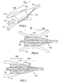
FIG. 5, in a perspective view, illustrates an optical coupler in accordance with another alternative embodiment of the invention optically coupled to three optical fibers;
FIG. 6, in a side cross-sectional view, illustrates the optical coupler shown in FIG. 5 coupled to three optical fiber in a first manner;
FIG. 7, in a side cross-sectional view, illustrates the optical coupler shown in FIGS. 5 and 6 coupled to three optical fiber in a second manner;
FIG. 8A, in a side cross-sectional view, illustrates an optical coupler in accordance with yet another alternative embodiment of the present invention optically coupled to two optical fibers;
FIG. 8B, in a side cross-sectional view, illustrates an optical coupler in accordance with yet another alternative embodiment of the present invention optically coupled to two optical fibers;
FIG. 9, in a rear elevation view, illustrates the optical coupler shown in FIG. 8;
FIG. 10, in a perspective view, illustrates an optical coupler in accordance with yet another embodiment of the invention optically coupled to two optical fibers;
FIG. 11, in a rear plan view, illustrates the optical coupler shown in FIG. 10;
FIG. 12, in a side cross-sectional view with parts removed, illustrates the optical coupler shown in FIGS. 10 and 11;
FIG. 13, in a perspective view, illustrates an optical coupler in accordance with yet another embodiment of the present invention optically coupled to one optical fiber;
FIG. 14, in a rear plan view, illustrates the optical coupler shown in FIG. 13;
FIG. 15, in a side elevation view, illustrates the optical coupler shown in FIGS. 13 and 14;
FIG. 16, in a side elevation view, illustrates an optical coupler in accordance with yet another embodiment of the present invention optically coupled to one optical fiber;
FIG. 17, in a rear plan view, illustrates the optical coupler shown in FIG. 16;
FIG. 18, in a side elevation view, illustrates an optical coupler in accordance with yet another embodiment of the present invention optically coupled to one optical fiber;
FIG. 19, in a rear plan view, illustrates the optical coupler shown in FIG. 18;
FIG. 20, in a side cross-sectional view, illustrates the optical coupler shown in FIGS. 1 to 3 optically coupled to two optical fibers, one of which is optically coupled outside of the optical coupler to a third optical fiber;
FIG. 21, in a side cross-sectional view, illustrates the optical coupler shown in FIGS. 1 to 3 optically coupled to two optical fibers, one of which is optically coupled at the end of the optical coupler to a third optical fiber;
FIG. 22, in a side cross-sectional view, illustrates the optical coupler shown in FIGS. 1 to 3 optically coupled to two optical fibers, one of which is optically coupled inside of the optical coupler to a third optical fiber;
FIG. 23, in perspective view, illustrates the optical coupler shown in FIGS. 1 to 3 optically coupled to five optical fibers, one of which is glued to the optical coupler inside a coupler passageway extending longitudinally through the optical coupler;
FIG. 24, in a side cross-sectional view, illustrates the optical coupler shown in FIG. 23;
FIG. 25, in a rear elevation, illustrates an optical coupler in accordance with yet another embodiment of the present invention, one of which is part of a fiber bundle inserted through a coupler passageway of the optical coupler;
FIG. 26A, in a perspective view, illustrates a first step in a method for manufacturing an optical coupler in accordance with yet another embodiment of the present invention;
FIG. 26B, in a perspective view, illustrates a second step in the method for manufacturing an optical coupler illustrated in FIG. 26A; and
FIG. 26C, in a perspective view, illustrates a third step in the method for manufacturing an optical coupler illustrated in FIGS. 26A and 26B.
DETAILED DESCRIPTION
FIGS. 1 to 3 illustrate an optical coupler 10 in accordance with an embodiment of the present invention. The optical coupler 10 is usable for optically coupling a first optical fiber 12 to a second optical fiber 16. In some embodiments of the invention, as seen in FIGS. 1 to 3, more than one optical fiber 12 are optically coupled to the second optical fiber 16. For example, these other optical fibers take the form of a bundle of optical fibers 13. In summary, the optical coupler 10 is manufacturable such that it includes a surface for coupling to the second optical fiber 16 in a substantially radial direction. The surface is formed so as to have a shape that substantially conforms to the outer surface of the second optical fiber 16.
The optical coupler 10 is configured and has optical properties such that essentially all the light incoming at the first optical fiber 12 is guided into the second optical fiber 16. Typically, this is achieved by adiabatically tapering the optical coupler 10 into the second optical fiber 16 substantially opposite to the first optical fiber 12. To that effect, the optical coupler 10 is configured so as to be substantially tangential to the second optical fiber at a location wherein the optical coupler 10 ceases to contact the optical fiber 16. This results in the optical coupler 10 coupling the light incoming at the first optical fiber 12, and at the other optical fibers of the bundle of optical fibers 13, to the cladding of the second optical fiber 16.
Typically, the optical coupling between the first optical fiber 12 and the second optical fiber 16 is a multimode coupling. In this case, the first optical fiber 12, and the other optical fibers 12 of the bundle of optical fibers 13 are multimode fibers. In various embodiments of the invention, the second optical fiber 16 is a multimode optical fiber, a multiple core optical fiber, a double-clad optical fiber, a single-mode optical fiber or any other suitable optical fiber.
Referring to FIG. 3, the first optical fiber 12 defines a first fiber free end 14. It should be understood that the first fiber free end 14 is here shown attached to the optical coupler 10. The term “free end” therefore applies to the configuration of the first optical fiber 12 before it is coupled to the optical coupler 10. Although not shown in the drawings, the first optical fiber 12 includes a first fiber core and a first fiber cladding extending substantially radially outwardly from the first fiber core.
Referring to FIG. 1, the second optical fiber 16 defines a second fiber free end 18. Also, as seen in FIG. 3, the second optical fiber 16 includes a second fiber core 24 and a second fiber cladding 26 extending substantially radially outwardly from the second fiber core 24. Typically, the second fiber core and cladding 24 and 26 are both substantially cylindrical. For clarity reasons, the second fiber core and cladding 24 and 26 are not distinguishly shown in the other Figures of the present application.
As better seen in FIG. 3, the second optical fiber 16 defines a second fiber coupling section 20 and a second fiber transmitting section 22 extending from the second fiber coupling section 20. The second fiber coupling section 20 defines a radially outwardmost peripheral surface 28. The radially outwardmost peripheral surface 28 is typically defined by the second fiber cladding 26. The radially outwardmost peripheral surface 28 defines a peripheral surface coupling portion 30. The peripheral surface coupling portion 30 is a portion of the radially outwardmost peripheral surface 28 through which light coming from the first optical fiber 12, or from other similarly located optical fibers, enters into the second optical fiber 16. In the optical coupler shown in FIGS. 1 to 3, the peripheral surface coupling portion 30 and the radially outwardmost peripheral surface 28 are substantially the same as light may enter the second optical fiber 16 from any direction.
The optical coupler 10 defines a coupler first end section 36 and a substantially opposed coupler second end section 38. The coupler first end section 36 defines a first coupling surface 40. Also, the optical coupler 10 defines a second coupling surface 42 extending along the coupler first and second end sections 36 and 38. In the embodiment of the invention shown in FIGS. 1 to 3, the coupler second end section 38 extend substantially longitudinally from the coupler first end section 36. However, in alternative embodiments of the invention, the coupler first and second end sections 36 and 38 are not adjacent to each other.
The first optical fiber 12 is optically coupled with the first coupling surface 40. Also, the peripheral surface coupling portion 30 is positionable so as to extend substantially parallel to the second coupling surface 42 and is optically coupled with the second coupling surface 42.
The optical coupler 10 has optical and geometrical properties such that substantially all the light guided to the first coupling surface 40 by the first optical fiber 12 is directed towards the second coupling surface 42 and into the second optical fiber 16 through the peripheral surface coupling portion 30 so as to be guided into the second fiber coupling section 20 for transmission into the second fiber transmitting section 22.
For example, this is achieved by having an optical coupler 10 that includes a tapered section 44 tapering in a direction leading from the coupler first end section 36 towards the coupler second end section 38. For example, and non-limitingly, the tapered section 44 is located substantially distally relatively to the first fiber free end 14 and extends substantially longitudinally from the coupler first end section 36. In a specific embodiment of the invention shown in FIGS. 1, 2 and 3, the coupler first end section 36 is substantially cylindrical and the coupler second end section 38 is substantially frusto-conical and therefore forms the tapered section 44. The rotational symmetry of these configurations facilitates manufacturing of the optical coupler 10 and the attachment of many optical fibers to the first coupling surface 40.
The optical coupler 10 defines a coupler passageway 46 extending along the coupler first and second end sections 36 and 38. More specifically, the coupler passageway 46 extends between the ends of the optical coupler 10. The second coupling surface 42 is located substantially peripherally relatively to the coupler passageway 46. In other words, the internal surface of the optical coupler 10 defining the coupler passageway 46 is, in this embodiment of the invention, the second coupling surface 42. The second coupling surface 42 is therefore substantially cylindrical. This configuration allows to have many optical fibers similar to the first optical fiber 12 attached to the optical coupler 10 such that the light incoming for all these optical fibers is guidable into the second optical fiber 16.
As seen in FIG. 1, the coupler passageway 46 is radially substantially centrally located relatively to the coupler first end section 36. However, it should be noted that, as described in further details hereinbelow, many other suitable shapes exist for the optical coupler 10.
As better seen in FIG. 24, in some embodiments of the invention, the peripheral surface coupling portion 30 is optically coupled to the second coupling surface 42 by a coupling medium 60 located between the second coupling surface 42 and the peripheral surface coupling portion 30. An example of such a coupling medium 60 is ethanol or any other suitable transparent liquid. Another example of such a coupling medium 60 is a bonding material. Typically, the coupling medium 60 has a refraction index substantially similar to the refraction index of the second fiber cladding 26 (not seen in FIG. 24). Also, typically, the optical coupler 10 has also the same refraction index as the second fiber cladding 26 (not seen in FIG. 24). In other embodiments of the invention, as seen in FIGS. 1 to 3, the second coupling surface 42 and the peripheral surface coupling portion 30 are fused to each other.
The diameter of the coupler first end section 36 is selected as a function of the diameters and numerical apertures of the first and second optical fibers 12 and 16 such that optimal coupling between the first and second optical fibers 12 and 16 occurs.
As an example, in an embodiment of this invention, a cylindrical tube of 800 μm external diameter and 405 μm internal diameter is used. The tube is cut to the length of 2 cm. The tube is then etched or polished to obtain a conical shape over 1 cm at one end as per FIGS. 1-3 to complete manufacturing of the optical coupler 10. At the cylindrical end, forming the coupler first end section 36, up to 9 200-micron core fibers (numerical aperture (NA) of 0.22) can be fused to the first coupling surface 40. Once this is done, a 20 μm core/400 μm diameter double clad fiber is first stripped of its low index polymer jacket (NA=0.46 for the guiding cladding), then is cleaved to about 3 cm of the fiber jacket end. This fiber end is then inserted into the coupler passageway 46 of the optical coupler 10 from the end adjacent the first coupling surface 40 so that it exits from the other end. A second 20/400 μm double clad fiber is stripped and cleaved and the ends of the last two fibers are aligned to transmit light. This alignment is optimized and the fibers are spliced using a heat source. The heat source is than gradually scanned towards the conical part of the optical coupler 10, which thus collapses on the internal fiber, thus creating a coupling between the tube and the inner fiber. This enable light guided from the multimode optical fiber to be coupled into the double-clad fiber with only a few percent loss. The thus obtain optical structure is then packaged for protection.
Another embodiment of this invention is obtained by following than same procedure as above but use a 340 μm external diameter tube with a 130 internal diameter. Then, 6 105 μm core fibers with 0.15 NA can be spliced to the tube and a 125 μm cladding diameter double-clad fiber can be inserted into the coupler passageway 46 and coupled thereto after fusioning the various parts. This assembly thereby formed is also relatively low loss.
As seen in FIG. 1, the first optical fiber 12 is substantially longitudinally coupled to the first coupling surface 40. In other words, the first coupling surface 40 is substantially perpendicular to the first optical fiber 12. In this embodiment of the invention, the first coupling surface 40 is also substantially perpendicular to the second coupling surface 42. In these embodiments, there is an optimization of numerical apertures of the first and second optical fibers 12 and 16 that are usable efficiently to transfer light from the first optical fiber 12 to the second optical fiber 16.
In use, the optical coupler 10 is provided separately from the first and second optical fibers 12 and 16. Then, the first optical fiber 12 is positioned substantially adjacent to the first coupling surface 40. Afterwards, the first optical fiber 12 is optically coupled to the first coupling surface 40. For example, this is performed by splicing the first optical fiber with the first coupling surface. Afterwards, the second optical fiber 16 is positioned such that the second coupling surface 42 is substantially adjacent and substantially parallel to the peripheral surface coupling portion 30. Then, the second coupling surface 42 and the peripheral surface coupling portion 30 are optically coupled to each other.
For example, the second coupling surface 42 and the peripheral surface coupling portion 30 are optically coupled to each other by fusing the second coupling surface 42 and the peripheral surface coupling portion 30 to each other. In other embodiments of the invention, the second coupling surface 42 and the peripheral surface coupling portion 30 are secured to each other using a bonding material.
As mentioned hereinabove, the first optical fiber 12 is typically optically coupled to the optical coupler 10 and secured thereto prior to optically coupling and securing the second optical fiber 16 to the optical coupler 10. The substantially cylindrical shape of coupler first end section 36 then facilitates assembly of the optical coupler 10 into a suitable package as the optical coupler 10 may then be held through this cylindrical portion of the optical coupler 10 instead of being held through the first optical fiber 12. This reduces surface stresses at the interface between the first optical fiber 12 and the optical coupler 10. Similarly, since the second optical fiber 16 is inserted through the coupler passageway 46, stresses at the interface between the second optical fiber 16 and the optical coupler 10 are also thereby minimized.
As shown in FIG. 4, in alternative embodiments of the invention, an optical coupler 710 includes 1 coupler passageway 746 having a first diameter 48 in the coupler first end section 36 and the coupler second end section 38 has a second diameter 50. The second diameter 50 is substantially smaller than the first diameter 48. For example, this may be achieved by providing a coupler passageway 746 of substantially uniform diameter and then collapsing the coupler passageway 746 onto the second optical fiber 16. However, in alternative embodiments of the invention, this configuration of diameters is pre-manufactured before the second optical fiber 16 is inserted through the coupler passageway 746.
These embodiments of the invention are particularly advantageous in applications wherein it is desirable that a sheath 27 of the second optical fiber 16 be partially inserted into the coupler passageway 746. However in alternative embodiments of the invention, the sheath 27 is not inserted in the coupler passageway 746.
As shown in FIGS. 5, 6 and 7, in alternative embodiments of the invention, the first optical fiber 12 is spliced to the radially outwardmost peripheral surface 137 of the coupler first end section 136 of an alternative optical coupler 110. In these embodiments of the invention, the first and second coupling surfaces 140 and 142, better seen in FIG. 6, are therefore parallel to each other, but this is not necessarily the case in all embodiments of the invention. This may be achieved by terminating the first optical fiber 12 at the optical coupler 110 or by tangentially optically coupling the first optical fiber 12 to the optical coupler 110. While FIG. 5 represents en embodiment of the invention wherein these two types of coupling are present simultaneously, typically all the first optical fibers 12 coupled to an optical coupler 110 either terminate at the optical coupler 110, as seen in FIG. 7, or are tangentially optically coupled to the first optical coupler 110, as seen in FIG. 6.
In yet other embodiments of the invention, as shown in FIGS. 8A and 9, an alternative optical coupler 210 includes a first tapered section 54 tapering in a direction leading from a coupler first end section 236 towards a coupler second end section 238 and a second tapered section 56 tapering in a direction leading from the coupler second end section 238 towards the coupler first end section 236. The second tapered section 56 extends substantially adjacent to the first tapered section 54 so as to define a neck 58 in the optical coupler. Typically, the second optical fiber 16 is optically coupled to the optical coupler 210 in a region substantially adjacent the neck 58. By reducing as much as possible the cross-sectional surface area of the optical coupler 210 in the vicinity of the neck 58, a relatively large portion of the light incoming at the first optical fiber 12 is guided into the second optical fiber 16. Also, in similar embodiments of the invention, this percentage of light coupled into second optical fiber 16 may be increased by having an optical coupler 210′ defining two or more necks 58, as shown in FIG. 8B. Furthermore, the power coupled into different sections of the second optical fiber 16 may be selected by varying a length over which the second optical fiber 16 is spaced apart from the internal surface of the coupler 210′ between the two necks 58.
As shown in FIGS. 10, 11 and 12, in some embodiments of the invention, the second coupling surface 330 (better shown in FIG. 11) of an alternative optical coupler 310 is shaped substantially similarly to a circumferentially interrupted segment of a cylindrical shell. Therefore, in these embodiments of the invention, the second optical fiber 16 is not inserted through a passageway present in the optical coupler, but is instead abutted against the second coupling surface 230 prior to being optically coupled thereto. This configuration is particularly advantageous when a relatively small number of optical fibers are to be coupled to the second optical fiber 16. Indeed, it is then relatively more easily achievable to optically couple the first and second optical fibers 12 and 16 in this manner as this reduces the effective surface area of the optical coupler 210 that is used to couple the light into the second optical fiber 16 and, therefore, increases a range of numerical apertures of the first and second optical fibers 12 and 16 that may be used with the optical coupler 310.
In yet other embodiments of the invention, an optical coupler 410, shown in FIGS. 13, 14 and 15, has first and second end sections 336 and 338 (better seen in FIG. 35) that have substantially polygonal cross-sections in a direction substantially perpendicular to the second optical fiber 16. For example, as seen more specifically in FIG. 13, the coupler first and second end sections 436 and 438 have a substantially hexagonal cross-sectional configuration. The use of a polygonal cross-section instead of a circular cross-section in manufacturing the optical coupler 410 reduces the effective surface area in a direction perpendicular to light propagation and, therefore, once again, optimizes the optical coupling of the first optical fibers 12 (only the footprint of which is shown) and the second optical fiber 16 to each other with regards to constraints put on numerical apertures.
It should be noted that in alternative embodiments of the invention, any other polygonal configuration may be taken by an alternative optical coupler similar to the optical coupler 410. Also, in yet other alternative embodiments of the invention, only one of the coupler first and second end sections 436 and 438 of a similar optical coupler has a polygonal configuration.
In these embodiments, the polygonal configuration of the optical coupler 410 results in the different modes carried into the optical coupler 410 through the first optical fiber 12 to be more easily mixed and, therefore, produce optimal coupling to the second optical fiber 16 over a relatively small longitudinal distance.
FIGS. 16 and 17 and FIGS. 18 and 19 respectively show optical couplers 510 and 610 according to yet other alternative embodiments of the present invention. Referring to FIG. 16, the optical coupler 510 is an optical coupler for which the coupler passageway 546 is radially substantially eccentrically located relatively to the coupler first end section 536. For example, this configuration is suitable for use when more than one optical fiber 12 must be optically coupled to the second optical fiber 16, but when the number of first optical fibers 12 is such that the use of a symmetrical optical coupler would cause undue constraints regarding the numerical apertures of the various optical fibers 12 and 16 that are coupled to each other. Disposing the second optical fiber 16 eccentrically relatively to the first optical fibers 12 allows to optimize the cross-sectional area of the optical coupler 10 as it relates to the ranges of numerical apertures of the optical coupler 510 and the first and second optical fibers 12 and 16 that are usable with each other.
The optical coupler 610 is usable, for example, in cases wherein the same optical fibers 12 are used to pump light into a second optical fiber 16 and a third optical fiber 17 that both extend through the optical coupler 610. To that effect, as seen for example in FIG. 18, the optical coupler 610 includes two coupler passageways 646 and 647 extending substantially longitudinally there through. Furthermore, in alternative embodiments of the invention, a similar optical coupler includes more than two coupler passageways.
It should be noted that, as seen in FIGS. 17 and 19, optical couplers 510 and 610 need not to have rotational symmetry about a longitudinal axis. Indeed, The optical couplers 510 and 610 have substantially ellipsoidal cross-sectional configuration, once again in the aim of having a cross-sectional surface that is as small as possible while allowing coupling of a number of optical fibers that is as large as possible.
As shown in FIGS. 20, 21 and 22, in some embodiments of the invention, the second optical fiber 16 is optically coupled also to a third optical fiber 32 which defines a third fiber free end 34. More specifically, the second and third fiber free ends 18 and 34 are positioned substantially adjacent to each other and are optically coupled such that light guided into the second optical fiber 16 is guided also into the third optical fiber 32. FIGS. 20, 21 and 22 respectively show embodiments of the invention wherein the second and third fiber free ends 18 and 34 are respectively located outside, at the end of and inside the coupler passageway 46. Also, in embodiments of the invention substantially similar to the optical coupler shown in FIGS. 8 and 9, the junction of the second and third optical fibers is typically located within the neck 58 of an optical coupler.
As seen in FIG. 25, in some embodiments of the invention, the second optical fiber 16 part of a bundle of optical fibers 19 inserted through a coupler passageway 846 of an alternative optical coupler 810. In these embodiments, optically coupling the first optical fiber 12 to the second optical fiber may include inserting the bundle of optical fibers 19 through a substantially cylindrical coupler passageway 846 and heating the optical coupler 810 so as to collapse the coupler passageway 846 onto the bundle of optical fibers 19.
In yet other embodiments of the invention, an alternative optical coupler 910 is manufactured as shown in FIGS. 26A to 26C. As seen in FIG. 26A, this method uses a section of an air-clad fiber 80. The air-clad fiber includes a core 82 surrounded by a cladding 84 defining longitudinally extending air holes 86. To manufacture the optical coupler 910, the cladding 84 is etched to form a neck 88, as seen in FIG. 26B. Typically, the cladding 84 is etched as much as practically feasible to obtain a relatively narrow neck 88. Then, the air holes 86 are collapsed around the core 82, at least on one side of the neck 88. Subsequently, the first optical fiber 12 is optically coupled to the cladding 84 and the second fiber core 24 is optically coupled to the core 82, as seen in FIG. 26C.
Although the present invention has been described hereinabove by way of preferred embodiments thereof, it can be modified, without departing from the spirit and nature of the subject invention as defined in the appended claims.

Claims (6)

1. A method for assembling an optical coupling assembly for optically coupling a first, a second and a third optical fiber using an optical coupler, said first, second, and third optical fibers defining respectively a first, a second and a third fiber free end, said optical coupler including a coupler first end section and a substantially opposed coupler second end section, said coupler first end section defining a first coupling surface, said coupler second end section defining a second coupling surface, said optical coupler defining a coupler passageway extending therealong between said coupler first and second end sections, said method comprising:
positioning said first fiber free end substantially adjacent to said first coupling surface;
optically coupling said first optical fiber and said first coupling surface to each other;
inserting said second optical fiber, at least partially, into said coupler passageway;
optically coupling said optical coupler second coupling surface and said second optical fiber to each other into said coupler passageway,
positioning said third fiber free end substantially adjacent to said second fiber free end; and
optically coupling said second and third fiber free ends to each other;
whereby light incoming in said optical coupler through said first coupling surface is guided by said optical coupler to pass through said second coupling surface and into said second optical fiber.
2. A method as defined in claim 1, wherein said second and third fiber free ends are positioned outside of said coupler passageway.
3. A method as defined in claim 1, wherein said second and third fiber free ends are positioned inside said coupler passageway.
4. A method as defined in claim 1, wherein said coupler passageway defines substantially opposed coupler passageway first and second ends located respectively substantially adjacent said coupler first and second end sections, said second and third fiber free ends being positioned substantially adjacent said coupler passageway second end.
5. A method as defined in claim 1, wherein
before inserting said second optical fiber, at least partially, into said coupler passageway, said coupler passageway has an inner diameter substantially larger than an outer diameter of said second optical fiber; and
optically coupling said optical coupler and said second optical fiber to each other into said coupler passageway includes collapsing said coupler passageway onto said second optical fiber.
6. A method as defined in claim 1, wherein said optical coupler defines a neck, said second and third fiber free ends being positioned substantially adjacent to said neck.
US11/976,476 2007-01-11 2007-10-25 Method and device for optically coupling optical fibres Expired - Fee Related US7539377B2 (en)

Priority Applications (1)

Application Number Priority Date Filing Date Title
US11/976,476 US7539377B2 (en) 2007-01-11 2007-10-25 Method and device for optically coupling optical fibres

Applications Claiming Priority (2)

Application Number Priority Date Filing Date Title
US87981707P 2007-01-11 2007-01-11
US11/976,476 US7539377B2 (en) 2007-01-11 2007-10-25 Method and device for optically coupling optical fibres

Publications (2)

Publication Number Publication Date
US20080170823A1 US20080170823A1 (en) 2008-07-17
US7539377B2 true US7539377B2 (en) 2009-05-26

Family

ID=39608288

Family Applications (2)

Application Number Title Priority Date Filing Date
US11/976,476 Expired - Fee Related US7539377B2 (en) 2007-01-11 2007-10-25 Method and device for optically coupling optical fibres
US12/448,807 Expired - Fee Related US8346038B2 (en) 2007-01-11 2008-01-10 Method and device for optically coupling optical fibres

Family Applications After (1)

Application Number Title Priority Date Filing Date
US12/448,807 Expired - Fee Related US8346038B2 (en) 2007-01-11 2008-01-10 Method and device for optically coupling optical fibres

Country Status (3)

Country Link
US (2) US7539377B2 (en)
EP (1) EP2122397A4 (en)
WO (1) WO2008083482A1 (en)

Cited By (12)

* Cited by examiner, † Cited by third party
Publication number Priority date Publication date Assignee Title
US20090129730A1 (en) * 2007-11-16 2009-05-21 Mitsubishi Cable Industries, Ltd. Double clad fiber and fiber end processing method, and fiber-combiner connecting structure including the same
US20090154879A1 (en) * 2007-12-14 2009-06-18 Arto Salokatve Means of Coupling Light Into Optical Fibers and Methods of Manufacturing a Coupler
US20100183260A1 (en) * 2009-01-22 2010-07-22 Raytheon Company Monolithic pump coupler for high-aspect ratio solid-state gain media
US8515220B1 (en) * 2012-04-12 2013-08-20 Raytheon Company Optical fiber coupler for coupling signal beams into a non-circularly shaped optical beam
US8873134B2 (en) 2008-08-21 2014-10-28 Nlight Photonics Corporation Hybrid laser amplifier system including active taper
US9063289B1 (en) 2008-06-30 2015-06-23 Nlight Photonics Corporation Multimode fiber combiners
US9158070B2 (en) 2008-08-21 2015-10-13 Nlight Photonics Corporation Active tapers with reduced nonlinearity
US9285541B2 (en) 2008-08-21 2016-03-15 Nlight Photonics Corporation UV-green converting fiber laser using active tapers
US9356418B2 (en) 2012-12-31 2016-05-31 Nlight, Inc. All fiber low dynamic pointing high power LMA fiber amplifier
US9484706B1 (en) 2012-06-12 2016-11-01 Nlight, Inc. Tapered core fiber manufacturing methods
US9484707B2 (en) 2012-12-31 2016-11-01 Nlight, Inc. Spatially stable high brightness fiber
US9494738B1 (en) 2009-05-28 2016-11-15 Nlight, Inc. Single mode fiber combiners

Families Citing this family (24)

* Cited by examiner, † Cited by third party
Publication number Priority date Publication date Assignee Title
US20130216184A1 (en) 2008-07-14 2013-08-22 Victor Il'ich Kopp Configurable pitch reducing optical fiber array
DE102008053728B4 (en) * 2008-10-29 2015-02-26 Trumpf Laser Gmbh Optical fiber arrangement
US8818151B1 (en) * 2009-08-03 2014-08-26 United States Of America As Represented By The Secretary Of The Air Force Fiber Pump Signal Combiner
EP2477284B1 (en) * 2009-10-27 2019-09-18 Fujikura Ltd. Light combiner and fiber laser device using same
KR20110068492A (en) * 2009-12-16 2011-06-22 한국전자통신연구원 Optic coupler and active optical module using the same
WO2011088569A1 (en) * 2010-01-22 2011-07-28 Genia Photonics Inc. Method and device for optically coupling optical fibres
JP5512348B2 (en) * 2010-03-29 2014-06-04 株式会社フジクラ Optical fiber for amplification with optical components, and fiber laser device using the same
US8953648B2 (en) 2010-07-30 2015-02-10 Ben-Gurion University Of The Negev Research & Development Authority Fiber laser pumping configuration and method
FI125306B (en) 2010-10-21 2015-08-31 Rofin Sinar Laser Gmbh Packaged fiber optic component and method of manufacture thereof
CN103477258B (en) 2011-02-03 2016-12-21 3Sae科技公司 Side pumping optical fiber, side pumping methods for optical fiber manufacture and use its Optical devices
US9025239B2 (en) * 2011-12-13 2015-05-05 Ofs Fitel, Llc Multi-core erbium-doped fiber amplifier
US9007681B2 (en) * 2011-12-13 2015-04-14 Ofs Fitel, Llc Multi-core erbium-doped fiber amplifier
CN102944917B (en) * 2012-11-22 2014-01-22 珠海保税区光联通讯技术有限公司 Erbium-doped optical fiber amplifier
CA2899953C (en) * 2013-02-01 2021-01-12 Polyvalor, Limited Partnership Asymmetric optical fiber coupler
US10914891B2 (en) 2013-06-14 2021-02-09 Chiral Photonics, Inc. Multichannel optical coupler
US10838155B2 (en) 2013-06-14 2020-11-17 Chiral Photonics, Inc. Multichannel optical coupler
US11966091B2 (en) 2013-06-14 2024-04-23 Chiral Photonics, Inc. Multichannel optical coupler array
US11156781B2 (en) 2013-06-14 2021-10-26 Chiral Photonics, Inc. Passive aligning optical coupler array
JP5814315B2 (en) * 2013-08-22 2015-11-17 株式会社フジクラ Optical combiner and laser device using the same
US9664850B2 (en) * 2014-09-21 2017-05-30 Alcatel-Lucent Usa Inc. Optical spatial mode-multiplexer
US9696493B2 (en) * 2014-11-13 2017-07-04 Ofs Fitel, Llc High efficiency pump signal combiner for high power fiber amplifier and laser applications
US10197736B2 (en) 2015-12-09 2019-02-05 Chiral Photonics, Inc. Polarization maintaining optical fiber array
EP3391110B1 (en) * 2015-12-31 2019-11-20 NLIGHT, Inc. Fiber pump combiner
JP6869298B2 (en) * 2019-08-09 2021-05-12 株式会社フジクラ Optical combiner, laser device, and manufacturing method of optical combiner

Citations (7)

* Cited by examiner, † Cited by third party
Publication number Priority date Publication date Assignee Title
US5815309A (en) * 1997-01-21 1998-09-29 Molecular Optoelectronics Corporation Optical amplifier and process for amplifying an optical signal propagating in a fiber optic
US6219480B1 (en) * 1999-01-29 2001-04-17 Fiberstars Incorporated Optical coupler for coupling light between one and a plurality of light ports
US6385371B1 (en) * 2000-04-03 2002-05-07 Cogent Light Technologies, Inc. Optical system including coupling for transmitting light between a single fiber light guide and multiple single fiber light guides
US6731837B2 (en) * 2000-11-28 2004-05-04 Keopsys, Inc. Optical fiber amplifiers and lasers and optical pumping devices therefor and methods of fabricating same
US20070031088A1 (en) * 2004-01-15 2007-02-08 University Of Delaware Optical coupler for coupling an optical fiber into a waveguide
US7277612B2 (en) * 2003-06-16 2007-10-02 Soreq Nuclear Research Center Optical apparatus including pump guiding fiber and receiving fiber
US20080050069A1 (en) * 2006-08-28 2008-02-28 Crystal Fibre A/S Optical coupler, a method of its fabrication and use

Family Cites Families (19)

* Cited by examiner, † Cited by third party
Publication number Priority date Publication date Assignee Title
GB1538195A (en) 1974-11-08 1979-01-10 Plessey Co Ltd Method and apparatus for detecting light radiated from or propogating light into optical fibres
US4021097A (en) 1976-03-08 1977-05-03 Sperry Rand Corporation Distributive tee coupler
DE3241774A1 (en) 1981-11-14 1983-06-23 Kei Tokyo Mori DEVICE FOR COLLECTING AND TRANSMITTING OPTICAL ENERGY USING TUBULAR LIGHT TRANSMISSION ELEMENTS
US5048026A (en) * 1983-09-30 1991-09-10 The Board Of Trustees Of The Leland Stanford Junior University Fiber optic amplifier
IL72845A0 (en) * 1983-09-30 1984-12-31 Univ Leland Stanford Junior Fiber optic amplifier
US5119453A (en) * 1991-04-05 1992-06-02 Ecole Polytechnique Wavelength-flattened 2x2 splitter for single-mode optical waveguides and method of making same
US5410626A (en) * 1992-06-25 1995-04-25 Kyocera Corporation Optical coupler having a tapered fused region
GB9403122D0 (en) * 1994-02-18 1994-04-06 Univ Southampton Acousto-optic device
ES2126879T3 (en) * 1994-12-28 1999-04-01 Italtel Spa COUPLING ARRANGEMENT BETWEEN A MULTIPLE MODE LIGHT SOURCE AND AN OPTICAL FIBER THROUGH AN INTERMEDIATE FIBER OPTIC SECTION.
US6477295B1 (en) * 1997-01-16 2002-11-05 Jds Uniphase Corporation Pump coupling of double clad fibers
US5966490A (en) * 1997-03-21 1999-10-12 Sdl, Inc. Clad optic fiber, and process for production thereof
DE19723267A1 (en) * 1997-06-03 1998-12-10 Heidelberger Druckmasch Ag Method and arrangement for reducing the pump light at the exit of a fiber laser
US6301412B1 (en) * 1997-06-27 2001-10-09 Shin-Etsu Chemical Co., Ltd. Apparatus and method for making multi-branching optical coupler
US6625354B2 (en) 2000-12-19 2003-09-23 The Boeing Company Fiber amplifier having a prism for efficient coupling of pump energy
CA2354903C (en) * 2001-08-08 2008-10-14 Itf Technologies Optiques Inc./Itf Optical Technologies Inc. Polarization-combining fused-fiber optical coupler and method of producing the same
FR2834347B1 (en) * 2002-01-03 2004-04-09 Cit Alcatel OPTICAL COUPLER FOR MULTIMODE PUMP
JP3795821B2 (en) * 2002-03-29 2006-07-12 日本発条株式会社 Optical splitter
US7046875B2 (en) * 2003-10-29 2006-05-16 Itf Technologies Optiques Inc. Optical coupler comprising multimode fibers and method of making the same
GB2439345A (en) 2006-06-23 2007-12-27 Gsi Group Ltd Annular tapered fibre coupler for cladding pumping of an optical fibre

Patent Citations (7)

* Cited by examiner, † Cited by third party
Publication number Priority date Publication date Assignee Title
US5815309A (en) * 1997-01-21 1998-09-29 Molecular Optoelectronics Corporation Optical amplifier and process for amplifying an optical signal propagating in a fiber optic
US6219480B1 (en) * 1999-01-29 2001-04-17 Fiberstars Incorporated Optical coupler for coupling light between one and a plurality of light ports
US6385371B1 (en) * 2000-04-03 2002-05-07 Cogent Light Technologies, Inc. Optical system including coupling for transmitting light between a single fiber light guide and multiple single fiber light guides
US6731837B2 (en) * 2000-11-28 2004-05-04 Keopsys, Inc. Optical fiber amplifiers and lasers and optical pumping devices therefor and methods of fabricating same
US7277612B2 (en) * 2003-06-16 2007-10-02 Soreq Nuclear Research Center Optical apparatus including pump guiding fiber and receiving fiber
US20070031088A1 (en) * 2004-01-15 2007-02-08 University Of Delaware Optical coupler for coupling an optical fiber into a waveguide
US20080050069A1 (en) * 2006-08-28 2008-02-28 Crystal Fibre A/S Optical coupler, a method of its fabrication and use

Cited By (18)

* Cited by examiner, † Cited by third party
Publication number Priority date Publication date Assignee Title
US20090129730A1 (en) * 2007-11-16 2009-05-21 Mitsubishi Cable Industries, Ltd. Double clad fiber and fiber end processing method, and fiber-combiner connecting structure including the same
US8094986B2 (en) * 2007-11-16 2012-01-10 Mitsubishi Cable Industries, Ltd. Double clad fiber and fiber end processing method, and fiber-combiner connecting structure including the same
US20090154879A1 (en) * 2007-12-14 2009-06-18 Arto Salokatve Means of Coupling Light Into Optical Fibers and Methods of Manufacturing a Coupler
US20090154882A1 (en) * 2007-12-14 2009-06-18 Arto Salokatve Means of Coupling Light Into Optical Fibers and Methods of Manufacturing a Coupler
US7991255B2 (en) 2007-12-14 2011-08-02 Corelase Oy Means of coupling light into optical fibers and methods of manufacturing a coupler
US9535217B1 (en) * 2008-06-30 2017-01-03 Nlight, Inc. Multimode fiber combiners
US9063289B1 (en) 2008-06-30 2015-06-23 Nlight Photonics Corporation Multimode fiber combiners
US9158070B2 (en) 2008-08-21 2015-10-13 Nlight Photonics Corporation Active tapers with reduced nonlinearity
US9285541B2 (en) 2008-08-21 2016-03-15 Nlight Photonics Corporation UV-green converting fiber laser using active tapers
US8873134B2 (en) 2008-08-21 2014-10-28 Nlight Photonics Corporation Hybrid laser amplifier system including active taper
US7978943B2 (en) * 2009-01-22 2011-07-12 Raytheon Company Monolithic pump coupler for high-aspect ratio solid-state gain media
US20100183260A1 (en) * 2009-01-22 2010-07-22 Raytheon Company Monolithic pump coupler for high-aspect ratio solid-state gain media
US9494738B1 (en) 2009-05-28 2016-11-15 Nlight, Inc. Single mode fiber combiners
US8515220B1 (en) * 2012-04-12 2013-08-20 Raytheon Company Optical fiber coupler for coupling signal beams into a non-circularly shaped optical beam
US9484706B1 (en) 2012-06-12 2016-11-01 Nlight, Inc. Tapered core fiber manufacturing methods
US9815731B1 (en) 2012-06-12 2017-11-14 Nlight, Inc. Tapered core fiber manufacturing methods
US9356418B2 (en) 2012-12-31 2016-05-31 Nlight, Inc. All fiber low dynamic pointing high power LMA fiber amplifier
US9484707B2 (en) 2012-12-31 2016-11-01 Nlight, Inc. Spatially stable high brightness fiber

Also Published As

Publication number Publication date
WO2008083482A1 (en) 2008-07-17
US8346038B2 (en) 2013-01-01
EP2122397A4 (en) 2012-07-11
US20100142894A1 (en) 2010-06-10
EP2122397A1 (en) 2009-11-25
US20080170823A1 (en) 2008-07-17

Similar Documents

Publication Publication Date Title
US7539377B2 (en) Method and device for optically coupling optical fibres
US6823117B2 (en) Mode multiplexing optical coupling device
JP5175282B2 (en) Apparatus for coupling radiant light into or out of an optical fiber
USRE44262E1 (en) Optical coupler comprising multimode fibers and method of making the same
US8085464B2 (en) Multi-clad optical fibre amplifier with optimized pumping
US20090154882A1 (en) Means of Coupling Light Into Optical Fibers and Methods of Manufacturing a Coupler
US8818151B1 (en) Fiber Pump Signal Combiner
JPH01118811A (en) Mode field modifier
JP5565088B2 (en) Optical fiber coupler, fiber laser, and manufacturing method of optical fiber coupler
US9494738B1 (en) Single mode fiber combiners
JP2012088733A (en) Optical coupler comprising multimode fiber and method of making the same
JP2003215387A (en) Optical coupler for multimode pump
EP2656129A1 (en) Optical couplers and methods for making same
WO2009080039A1 (en) Optical combiner and method of producing the same
JP5583690B2 (en) Splice junction between two optical fibers and method of making the splice junction
JP5933561B2 (en) NA reduction of fiber optic coupler
US8891920B2 (en) Method and device for optically coupling optical fibres
KR101544455B1 (en) Optical fiber pump-signal combiner and method of manufacturing for pump-signal combiner
KR102001201B1 (en) Optical coupler, forming method of the same and optical amplifier comprising the same
JP2010141086A (en) Optical fiber coupler, optical amplifying device, and fiber laser
JP2004219890A (en) Porous structure optical fiber and light beam incidence method using the same
Peterka et al. Novel coupling element for end-pumping of double-clad fibres

Legal Events

Date Code Title Description
STCF Information on status: patent grant

Free format text: PATENTED CASE

AS Assignment

Owner name: 9180-8030 QUEBEC INC., QUEBEC

Free format text: ASSIGNMENT OF ASSIGNORS INTEREST;ASSIGNOR:GONTHIER, FRANCOIS;REEL/FRAME:027063/0471

Effective date: 20111013

AS Assignment

Owner name: 9180-8030 QUEBEC INC., CANADA

Free format text: CORRECTIVE ASSIGNMENT TO CORRECT THE POSTAL CODE IN THE ADDRESS OF THE ASSIGNOR FROM G1S 2P8 TO G1S 1P8 PREVIOUSLY RECORDED ON REEL 027063 FRAME 0471. ASSIGNOR(S) HEREBY CONFIRMS THE ASSIGNMENT;ASSIGNOR:GONTHIER, FRANCOIS;REEL/FRAME:027159/0308

Effective date: 20111013

FPAY Fee payment

Year of fee payment: 4

REMI Maintenance fee reminder mailed
FPAY Fee payment

Year of fee payment: 8

SULP Surcharge for late payment

Year of fee payment: 7

FEPP Fee payment procedure

Free format text: MAINTENANCE FEE REMINDER MAILED (ORIGINAL EVENT CODE: REM.); ENTITY STATUS OF PATENT OWNER: SMALL ENTITY

LAPS Lapse for failure to pay maintenance fees

Free format text: PATENT EXPIRED FOR FAILURE TO PAY MAINTENANCE FEES (ORIGINAL EVENT CODE: EXP.); ENTITY STATUS OF PATENT OWNER: SMALL ENTITY

STCH Information on status: patent discontinuation

Free format text: PATENT EXPIRED DUE TO NONPAYMENT OF MAINTENANCE FEES UNDER 37 CFR 1.362

FP Lapsed due to failure to pay maintenance fee

Effective date: 20210526