US7535633B2 - Laser amplifiers with high gain and small thermal aberrations - Google Patents
Laser amplifiers with high gain and small thermal aberrations Download PDFInfo
- Publication number
- US7535633B2 US7535633B2 US11/328,450 US32845006A US7535633B2 US 7535633 B2 US7535633 B2 US 7535633B2 US 32845006 A US32845006 A US 32845006A US 7535633 B2 US7535633 B2 US 7535633B2
- Authority
- US
- United States
- Prior art keywords
- laser
- solid
- gain
- active solid
- active
- Prior art date
- Legal status (The legal status is an assumption and is not a legal conclusion. Google has not performed a legal analysis and makes no representation as to the accuracy of the status listed.)
- Active, expires
Links
Images


Classifications
-
- H—ELECTRICITY
- H01—ELECTRIC ELEMENTS
- H01S—DEVICES USING THE PROCESS OF LIGHT AMPLIFICATION BY STIMULATED EMISSION OF RADIATION [LASER] TO AMPLIFY OR GENERATE LIGHT; DEVICES USING STIMULATED EMISSION OF ELECTROMAGNETIC RADIATION IN WAVE RANGES OTHER THAN OPTICAL
- H01S3/00—Lasers, i.e. devices using stimulated emission of electromagnetic radiation in the infrared, visible or ultraviolet wave range
- H01S3/09—Processes or apparatus for excitation, e.g. pumping
- H01S3/091—Processes or apparatus for excitation, e.g. pumping using optical pumping
- H01S3/094—Processes or apparatus for excitation, e.g. pumping using optical pumping by coherent light
- H01S3/0941—Processes or apparatus for excitation, e.g. pumping using optical pumping by coherent light of a laser diode
-
- H—ELECTRICITY
- H01—ELECTRIC ELEMENTS
- H01S—DEVICES USING THE PROCESS OF LIGHT AMPLIFICATION BY STIMULATED EMISSION OF RADIATION [LASER] TO AMPLIFY OR GENERATE LIGHT; DEVICES USING STIMULATED EMISSION OF ELECTROMAGNETIC RADIATION IN WAVE RANGES OTHER THAN OPTICAL
- H01S3/00—Lasers, i.e. devices using stimulated emission of electromagnetic radiation in the infrared, visible or ultraviolet wave range
- H01S3/02—Constructional details
- H01S3/04—Arrangements for thermal management
- H01S3/042—Arrangements for thermal management for solid state lasers
-
- H—ELECTRICITY
- H01—ELECTRIC ELEMENTS
- H01S—DEVICES USING THE PROCESS OF LIGHT AMPLIFICATION BY STIMULATED EMISSION OF RADIATION [LASER] TO AMPLIFY OR GENERATE LIGHT; DEVICES USING STIMULATED EMISSION OF ELECTROMAGNETIC RADIATION IN WAVE RANGES OTHER THAN OPTICAL
- H01S3/00—Lasers, i.e. devices using stimulated emission of electromagnetic radiation in the infrared, visible or ultraviolet wave range
- H01S3/05—Construction or shape of optical resonators; Accommodation of active medium therein; Shape of active medium
- H01S3/06—Construction or shape of active medium
- H01S3/0602—Crystal lasers or glass lasers
- H01S3/0604—Crystal lasers or glass lasers in the form of a plate or disc
-
- H—ELECTRICITY
- H01—ELECTRIC ELEMENTS
- H01S—DEVICES USING THE PROCESS OF LIGHT AMPLIFICATION BY STIMULATED EMISSION OF RADIATION [LASER] TO AMPLIFY OR GENERATE LIGHT; DEVICES USING STIMULATED EMISSION OF ELECTROMAGNETIC RADIATION IN WAVE RANGES OTHER THAN OPTICAL
- H01S3/00—Lasers, i.e. devices using stimulated emission of electromagnetic radiation in the infrared, visible or ultraviolet wave range
- H01S3/05—Construction or shape of optical resonators; Accommodation of active medium therein; Shape of active medium
- H01S3/06—Construction or shape of active medium
- H01S3/063—Waveguide lasers, i.e. whereby the dimensions of the waveguide are of the order of the light wavelength
- H01S3/0632—Thin film lasers in which light propagates in the plane of the thin film
-
- H—ELECTRICITY
- H01—ELECTRIC ELEMENTS
- H01S—DEVICES USING THE PROCESS OF LIGHT AMPLIFICATION BY STIMULATED EMISSION OF RADIATION [LASER] TO AMPLIFY OR GENERATE LIGHT; DEVICES USING STIMULATED EMISSION OF ELECTROMAGNETIC RADIATION IN WAVE RANGES OTHER THAN OPTICAL
- H01S2301/00—Functional characteristics
- H01S2301/02—ASE (amplified spontaneous emission), noise; Reduction thereof
-
- H—ELECTRICITY
- H01—ELECTRIC ELEMENTS
- H01S—DEVICES USING THE PROCESS OF LIGHT AMPLIFICATION BY STIMULATED EMISSION OF RADIATION [LASER] TO AMPLIFY OR GENERATE LIGHT; DEVICES USING STIMULATED EMISSION OF ELECTROMAGNETIC RADIATION IN WAVE RANGES OTHER THAN OPTICAL
- H01S3/00—Lasers, i.e. devices using stimulated emission of electromagnetic radiation in the infrared, visible or ultraviolet wave range
- H01S3/005—Optical devices external to the laser cavity, specially adapted for lasers, e.g. for homogenisation of the beam or for manipulating laser pulses, e.g. pulse shaping
-
- H—ELECTRICITY
- H01—ELECTRIC ELEMENTS
- H01S—DEVICES USING THE PROCESS OF LIGHT AMPLIFICATION BY STIMULATED EMISSION OF RADIATION [LASER] TO AMPLIFY OR GENERATE LIGHT; DEVICES USING STIMULATED EMISSION OF ELECTROMAGNETIC RADIATION IN WAVE RANGES OTHER THAN OPTICAL
- H01S3/00—Lasers, i.e. devices using stimulated emission of electromagnetic radiation in the infrared, visible or ultraviolet wave range
- H01S3/02—Constructional details
- H01S3/025—Constructional details of solid state lasers, e.g. housings or mountings
-
- H—ELECTRICITY
- H01—ELECTRIC ELEMENTS
- H01S—DEVICES USING THE PROCESS OF LIGHT AMPLIFICATION BY STIMULATED EMISSION OF RADIATION [LASER] TO AMPLIFY OR GENERATE LIGHT; DEVICES USING STIMULATED EMISSION OF ELECTROMAGNETIC RADIATION IN WAVE RANGES OTHER THAN OPTICAL
- H01S3/00—Lasers, i.e. devices using stimulated emission of electromagnetic radiation in the infrared, visible or ultraviolet wave range
- H01S3/02—Constructional details
- H01S3/04—Arrangements for thermal management
- H01S3/0407—Liquid cooling, e.g. by water
-
- H—ELECTRICITY
- H01—ELECTRIC ELEMENTS
- H01S—DEVICES USING THE PROCESS OF LIGHT AMPLIFICATION BY STIMULATED EMISSION OF RADIATION [LASER] TO AMPLIFY OR GENERATE LIGHT; DEVICES USING STIMULATED EMISSION OF ELECTROMAGNETIC RADIATION IN WAVE RANGES OTHER THAN OPTICAL
- H01S3/00—Lasers, i.e. devices using stimulated emission of electromagnetic radiation in the infrared, visible or ultraviolet wave range
- H01S3/05—Construction or shape of optical resonators; Accommodation of active medium therein; Shape of active medium
- H01S3/06—Construction or shape of active medium
- H01S3/0602—Crystal lasers or glass lasers
- H01S3/0606—Crystal lasers or glass lasers with polygonal cross-section, e.g. slab, prism
-
- H—ELECTRICITY
- H01—ELECTRIC ELEMENTS
- H01S—DEVICES USING THE PROCESS OF LIGHT AMPLIFICATION BY STIMULATED EMISSION OF RADIATION [LASER] TO AMPLIFY OR GENERATE LIGHT; DEVICES USING STIMULATED EMISSION OF ELECTROMAGNETIC RADIATION IN WAVE RANGES OTHER THAN OPTICAL
- H01S3/00—Lasers, i.e. devices using stimulated emission of electromagnetic radiation in the infrared, visible or ultraviolet wave range
- H01S3/05—Construction or shape of optical resonators; Accommodation of active medium therein; Shape of active medium
- H01S3/06—Construction or shape of active medium
- H01S3/0602—Crystal lasers or glass lasers
- H01S3/0612—Non-homogeneous structure
-
- H—ELECTRICITY
- H01—ELECTRIC ELEMENTS
- H01S—DEVICES USING THE PROCESS OF LIGHT AMPLIFICATION BY STIMULATED EMISSION OF RADIATION [LASER] TO AMPLIFY OR GENERATE LIGHT; DEVICES USING STIMULATED EMISSION OF ELECTROMAGNETIC RADIATION IN WAVE RANGES OTHER THAN OPTICAL
- H01S3/00—Lasers, i.e. devices using stimulated emission of electromagnetic radiation in the infrared, visible or ultraviolet wave range
- H01S3/05—Construction or shape of optical resonators; Accommodation of active medium therein; Shape of active medium
- H01S3/06—Construction or shape of active medium
- H01S3/0602—Crystal lasers or glass lasers
- H01S3/0615—Shape of end-face
-
- H—ELECTRICITY
- H01—ELECTRIC ELEMENTS
- H01S—DEVICES USING THE PROCESS OF LIGHT AMPLIFICATION BY STIMULATED EMISSION OF RADIATION [LASER] TO AMPLIFY OR GENERATE LIGHT; DEVICES USING STIMULATED EMISSION OF ELECTROMAGNETIC RADIATION IN WAVE RANGES OTHER THAN OPTICAL
- H01S3/00—Lasers, i.e. devices using stimulated emission of electromagnetic radiation in the infrared, visible or ultraviolet wave range
- H01S3/09—Processes or apparatus for excitation, e.g. pumping
- H01S3/091—Processes or apparatus for excitation, e.g. pumping using optical pumping
- H01S3/094—Processes or apparatus for excitation, e.g. pumping using optical pumping by coherent light
- H01S3/094049—Guiding of the pump light
- H01S3/094053—Fibre coupled pump, e.g. delivering pump light using a fibre or a fibre bundle
-
- H—ELECTRICITY
- H01—ELECTRIC ELEMENTS
- H01S—DEVICES USING THE PROCESS OF LIGHT AMPLIFICATION BY STIMULATED EMISSION OF RADIATION [LASER] TO AMPLIFY OR GENERATE LIGHT; DEVICES USING STIMULATED EMISSION OF ELECTROMAGNETIC RADIATION IN WAVE RANGES OTHER THAN OPTICAL
- H01S3/00—Lasers, i.e. devices using stimulated emission of electromagnetic radiation in the infrared, visible or ultraviolet wave range
- H01S3/09—Processes or apparatus for excitation, e.g. pumping
- H01S3/091—Processes or apparatus for excitation, e.g. pumping using optical pumping
- H01S3/094—Processes or apparatus for excitation, e.g. pumping using optical pumping by coherent light
- H01S3/094049—Guiding of the pump light
- H01S3/094057—Guiding of the pump light by tapered duct or homogenized light pipe, e.g. for concentrating pump light
-
- H—ELECTRICITY
- H01—ELECTRIC ELEMENTS
- H01S—DEVICES USING THE PROCESS OF LIGHT AMPLIFICATION BY STIMULATED EMISSION OF RADIATION [LASER] TO AMPLIFY OR GENERATE LIGHT; DEVICES USING STIMULATED EMISSION OF ELECTROMAGNETIC RADIATION IN WAVE RANGES OTHER THAN OPTICAL
- H01S3/00—Lasers, i.e. devices using stimulated emission of electromagnetic radiation in the infrared, visible or ultraviolet wave range
- H01S3/09—Processes or apparatus for excitation, e.g. pumping
- H01S3/091—Processes or apparatus for excitation, e.g. pumping using optical pumping
- H01S3/094—Processes or apparatus for excitation, e.g. pumping using optical pumping by coherent light
- H01S3/094084—Processes or apparatus for excitation, e.g. pumping using optical pumping by coherent light with pump light recycling, i.e. with reinjection of the unused pump light, e.g. by reflectors or circulators
-
- H—ELECTRICITY
- H01—ELECTRIC ELEMENTS
- H01S—DEVICES USING THE PROCESS OF LIGHT AMPLIFICATION BY STIMULATED EMISSION OF RADIATION [LASER] TO AMPLIFY OR GENERATE LIGHT; DEVICES USING STIMULATED EMISSION OF ELECTROMAGNETIC RADIATION IN WAVE RANGES OTHER THAN OPTICAL
- H01S3/00—Lasers, i.e. devices using stimulated emission of electromagnetic radiation in the infrared, visible or ultraviolet wave range
- H01S3/14—Lasers, i.e. devices using stimulated emission of electromagnetic radiation in the infrared, visible or ultraviolet wave range characterised by the material used as the active medium
- H01S3/16—Solid materials
- H01S3/1601—Solid materials characterised by an active (lasing) ion
- H01S3/1603—Solid materials characterised by an active (lasing) ion rare earth
- H01S3/1611—Solid materials characterised by an active (lasing) ion rare earth neodymium
-
- H—ELECTRICITY
- H01—ELECTRIC ELEMENTS
- H01S—DEVICES USING THE PROCESS OF LIGHT AMPLIFICATION BY STIMULATED EMISSION OF RADIATION [LASER] TO AMPLIFY OR GENERATE LIGHT; DEVICES USING STIMULATED EMISSION OF ELECTROMAGNETIC RADIATION IN WAVE RANGES OTHER THAN OPTICAL
- H01S3/00—Lasers, i.e. devices using stimulated emission of electromagnetic radiation in the infrared, visible or ultraviolet wave range
- H01S3/14—Lasers, i.e. devices using stimulated emission of electromagnetic radiation in the infrared, visible or ultraviolet wave range characterised by the material used as the active medium
- H01S3/16—Solid materials
- H01S3/163—Solid materials characterised by a crystal matrix
- H01S3/1671—Solid materials characterised by a crystal matrix vanadate, niobate, tantalate
- H01S3/1673—YVO4 [YVO]
-
- H—ELECTRICITY
- H01—ELECTRIC ELEMENTS
- H01S—DEVICES USING THE PROCESS OF LIGHT AMPLIFICATION BY STIMULATED EMISSION OF RADIATION [LASER] TO AMPLIFY OR GENERATE LIGHT; DEVICES USING STIMULATED EMISSION OF ELECTROMAGNETIC RADIATION IN WAVE RANGES OTHER THAN OPTICAL
- H01S3/00—Lasers, i.e. devices using stimulated emission of electromagnetic radiation in the infrared, visible or ultraviolet wave range
- H01S3/23—Arrangements of two or more lasers not provided for in groups H01S3/02 - H01S3/22, e.g. tandem arrangements of separate active media
- H01S3/2308—Amplifier arrangements, e.g. MOPA
- H01S3/2325—Multi-pass amplifiers, e.g. regenerative amplifiers
- H01S3/2333—Double-pass amplifiers
-
- H—ELECTRICITY
- H01—ELECTRIC ELEMENTS
- H01S—DEVICES USING THE PROCESS OF LIGHT AMPLIFICATION BY STIMULATED EMISSION OF RADIATION [LASER] TO AMPLIFY OR GENERATE LIGHT; DEVICES USING STIMULATED EMISSION OF ELECTROMAGNETIC RADIATION IN WAVE RANGES OTHER THAN OPTICAL
- H01S3/00—Lasers, i.e. devices using stimulated emission of electromagnetic radiation in the infrared, visible or ultraviolet wave range
- H01S3/23—Arrangements of two or more lasers not provided for in groups H01S3/02 - H01S3/22, e.g. tandem arrangements of separate active media
- H01S3/2308—Amplifier arrangements, e.g. MOPA
- H01S3/2325—Multi-pass amplifiers, e.g. regenerative amplifiers
- H01S3/2341—Four pass amplifiers
Definitions
- the present invention relates to solid state laser amplifiers and laser gain modules for high power laser resonators.
- Compact, efficient, high gain amplifiers and laser resonators are needed in a variety of applications in which one requires high output laser powers in the smallest package possible. These applications include high power free space amplifiers for fibre oscillators [ 1 ] and amplifiers for short pulsed laser systems as a means to replace complex regenerative amplifiers [ 2 ].
- the use of high power and high gain amplifiers enables a new class of compact high peak power and high average power laser sources for material processing, laser manufacturing, and medical and dental applications for the highest processing speeds possible.
- Solid state laser technology has now advanced up to the point where the average powers and peak power of pulsed sources has reached a threshold where a number of new applications is now possible. These applications have been greatly limited in scope due to the lack of sufficiently compact, low cost, robust laser system technology to move beyond the demonstration phase. If the laser technology can be made robust and more cost effective a number of important applications are on the horizon.
- pulsed laser applications It is under pulsed conditions that is possible to delivery energy to a material quickly, strongly localized the absorbed energy, and thereby raise the temperature of the material to its highest point to drive ablation processes in reshaping the material to a desired product [ 3 ].
- the process of laser ablation and cutting, laser marking, etc. are more efficient the more strongly localized the energy is within the material both spatially and temporally.
- the conditions of confinement of the exciting pump light to achieve the highest gain conditions increases the heat deposited per unit area and the associated thermal gradients such that the problem of thermal aberrations becomes compounded.
- This problem not only limits the extractable gain but also destroys pulse quality by adding long tails to the amplified pulse which as explained above is highly deleterious to avoiding accumulated thermal damage in laser processing.
- ASE is most significant when the laser gain medium is being used as an amplifier; within a properly designed laser resonator these stimulated photons contribute to the laser beam rather than behave parasitically.
- Optimal designs of high gain amplifiers/gain media must specifically address thermal aberrations and ASE issues from diminishing beam quality and efficiency. Of these two issues, the thermal aberrations are most limiting with respect to power scaling and laser brightness.
- One strategy is to try to minimize the magnitude of the thermal aberrations themselves for example by employing designs that lead to faster heat transfer to keep the laser gain medium cooled [ 4 ], more uniform cooling to reduce index of refraction gradients in the transverse direction of beam propagation so that all parts of the laser beam experience the same index of refraction spatial profile [ 6 , 7 ], and the use of cooling to reduce the magnitude of the change in the index of refraction with temperature by reducing the thermal expansion [ 8 ].
- the other strategy is to use beam configurations for sampling the pumped gain region in such a way as to average out the thermal aberrations as much as possible such that all parts of the laser beam experience the same spatial profile for the index of refraction and thereby remove thermal lensing and aberration effects [ 9 , 10 ].
- Brauch et al. have disclosed the use of thin disc laser gain media in which thermal aberrations are removed for laser beams coming in perpendicular to a cooled surface [ 6 ]. Under uniform pumping conditions, there are no transverse components to the index of refraction spatial profile experienced by the laser beam in the gain medium for this configuration.
- Wittrock [ 7 ] has used the concept of removal of thermal aberrations in which the laser beam to be amplified is brought in at a very small angle to the cooled surface, rather than normal to the surface as in the Brauch et al design [ 6 ], to enable cancellation of the thermal gradients upon reflection as first described by Alcock and Bernard [ 10 ] in the grazing incidence amplifier design.
- the relatively large acute angle to the surface normal enables a much longer interaction region with the gain media and fewer passes to achieve the same overall gain as the thin disc concept of Brauch et al.
- both the Wittrock and Brauch et al. designs require uniform pumping over the entire laser active solid to rigorously provide 1 dimensional cooling. If uniform pumping is not accomplished the concept fails to remove thermal aberrations. Furthermore, the condition of uniform pumping greatly reduces the power extraction efficiency while maintaining high brightness for the laser beam to be amplified.
- Laser amplifiers with lower gain require more round trips to extract the same power as high gain systems and thereby experience more loss.
- it is possible to have 100% percent reflectors such that a low gain system requiring up to 10 passes or more to extract power has the same efficiency as a much higher gain system that only requires one pass.
- high gain systems are essential to reduce the dimensions, number of optical surfaces involved in beam transport into and out of the laser gain medium, and the overall path length traversed by the laser beam to be amplified to attain maximum stability and efficiency.
- the Wittrock design is capable of higher overall gain per pass relative to the Brauch et al design, however it relies on completely uniform pumping of the laser active material.
- the laser beam to be amplified in this design concept is brought in appreciably perpendicular to the normal of the cooled surface such that the beam experiences all nonparallel components to the isotherms.
- the laser beam to be amplified or resonator beam must be significantly smaller in diameter than the uniformly pumped gain region to avoid diffraction losses and nonparallel isotherms from edge effects.
- the only way to increase the gain of the laser active solid in this design concept is to increase the pumping uniformly.
- the present invention provides a solid state laser amplifier system which overcomes these limitations in achieving high gain and beam quality by using a combination of thin laser gain media with laser beam propagation paths along different axes that substantially cancel the thermal aberrations and permit the use of nonuniform pumping for high gain.
- a solid-state laser amplifier system comprising:
- At least one laser-active solid having dimensions length L 1 , width W 1 , and thickness t 1 ;
- c) light beam shaping optical system positioned adjacent to the pumping light source for shaping and directing a pump light beam from said pumping light source into a first surface of said at least one laser-active solid with an elliptical, round, or rectangular beam of light with a length or long axis L 1 ′ and a width W 1 ′ satisfying a condition L 1 ′/W 1 ′ ⁇ 1 and L 1 ′ ⁇ L 1 and width W 1 ′ ⁇ W 1 , and wherein a region of said at least one laser-active solid illuminated by the beam of light produces a pumped gain region defined by dimensions L 1 ′ ⁇ W 1′ ⁇ t 1 of said at least one laser-active solid, and wherein t 1 is in a range from 10 microns to 1 millimeter so as to most strongly localize the absorbed light and ensuing pumped gain region that develops from pumping said at least one laser-active solid with said pump light;
- the laser-active solid is slab-shaped and is fixedly connected at a second surface thereof to the cooling device, and wherein a major portion of heat generated in the laser-active solid by the pump light is removed by the cooling device to cool the second surface of the laser-active solid and, wherein the slab-shaped laser active solid includes periodically disposed channels of length between about 0.1 micron to about 100 microns, said channels being filled with an absorbing material or scattering centers to introduce regions of absorption and scattering losses along a direction defined by L 1 and prevent accumulated stimulate emission along the L 1 ′ pumped region from depleting the gain in this direction and accompanying reduction in pulse quality for use in the amplification of laser pulses; and
- an optical system configured to bring the laser beam to be amplified into the laser active solid at an angle to a normal to the first surface of the laser active solid to remove substantially nonparallel isotherms that arise from nonuniform pumping of the laser active solid by the pump light beam and cooling requirements to achieve high gain conditions for the laser beam.
- FIG. 1( a ) is a top view showing a solid-state laser amplifier system with a diode laser array pump light source;
- FIG. 1( b ) is a side view of the laser amplifier of FIG. 1( a ) in which details of the system when used with vertically stacked diode array can be visualized;
- FIG. 1( c ) shows a side view of an embodiment of an amplifier which increases pump absorption by a multipass optical system
- FIG. 1( d ) shows an embodiment of a solid state laser amplifier with cryogenic cooling
- FIG. 2( a ) shows part of the laser amplifier showing the laser active solid and laser inactive solid and dimensions used for these components;
- FIG. 2( b ) is similar to FIG. 2( a ) but a different configuration of the laser inactive solid coupled to the laser active solid;
- FIG. 3 shows temperature and gain profile in the laser gain region of the solid state laser amplifier along x, y, and z direction;
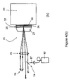
- FIG. 4( a ) shows an embodiment of a solid state laser amplifier with a fiber coupled laser diode with separated pump beam and seed laser
- FIG. 4( b ) shows an embodiment of a solid state laser amplifier with a fiber coupled laser diode with spatially co-propagating pump and seed laser beams in a multipass configuration
- FIG. 5 shows an embodiment of a solid state laser amplifier with a laser diode stack plus lens duct.
- Inset details of thin laser active solid with a sandwich structure used for gain confinement;
- FIG. 6( a ) shows an embodiment of a solid state laser amplifier in which the laser beam follows a zig-zag path along z direction;
- FIG. 6( b ) shows an embodiment of a solid state laser amplifier in which the laser beam follows a higher order zig-zag path
- FIG. 7 shows an embodiment of the laser gain medium used in the solid state laser amplifier which reduces or prevents ASE.
- FIGS. 8 a and 8 b show another embodiment of a solid state laser amplifier according to the present invention.
- the present invention provides a solid-state laser amplifier system for amplifying laser pulses.
- Basic elements of the solid-state laser amplifier system include: 1) a thin active laser solid of thickness t to absorb light from an appropriate light source (the pump) to create the population inversion and associated heat generation within the smallest value of t possible for the desired output power of the device; 2) a pump source comprised of a laser diode or arrays of laser diodes tuned to the maximum absorption of the laser active atom, ion, or molecule; 3) an optical system to transport the pump light to the laser active solid in such a way as to further confine the absorption of light along the two orthogonal directions in the plane of the thin laser active solid; 4) contact of the thin active laser solid to a cooling device with an appropriate material to give good heat transport and high reflectivity of light at the pump and laser wavelengths; 5) a cooling device that maintains the temperature of the active laser solid under pumped conditions at the temperature at which the temperature dependent variations of the index of refraction of the said active solid are sufficiently
- Preferred embodiments may also include an appropriate non-active laser solid, typically the same as the host material used for the laser active solid fused or bonded [ 13 ] or some other mechanical means to the laser active solid, to provide mechanical support for the thin laser active solid and which is shaped in such a way as to enable the coupling of the incoming and output beams within such a way for canceling the thermal aberrations and also to act as a heat buffer for the heat generated at the surface of the said active solid and thus reducing thermal aberrations even further.
- the system may be designed to provide for multipasses of the pump beam through the laser active solid to increase the amount of light absorbed in the desired volume or gain and to achieve an even greater degree of averaging out thermal induced differences in the index of refraction experience by the laser beam.
- the system may also include periodically introduced absorber or other loss structures along the pumped gain region of the laser active solid as needed to minimize ASE effects from depleting the stored gain in the laser active media for obtaining higher gain in the amplification of the laser beam.
- spatial filters may be used for the laser beam which are placed between subsequent passes of the laser beam being amplified through the active solid in order to improve the beam quality of the amplified laser beam.
- An important physical feature of this invention is the use of a very thin laser active solid.
- the dimensions of t 1 will typically be between 10 microns and 500 microns, depending on the absorptivity of the laser active solid at the pump wavelength.
- the dimension t 1 is made as small as possible while still large enough to enable more than 50% absorption of the pump light with the optical system used for transporting the pump light. This value should be compared to more typical laser rod dimensions of 5 mm; there is an order of magnitude reduction in the dimension of one principle dimension of the laser active solid over conventional laser rods.
- the use of a thin laser active solid is used specifically to confine the absorbed pump energy to ensure that any heat (q) generation occurs as close as possible to a heat sink.
- the rate of heat transfer to a heat sink scales inversely to the length scale squared over which the heat is generated. The closer the heat can be generated to a heat sink the faster the heat can be removed from the material.
- the rate of heat transfer (dq/dt) is also proportional to the driving force in this case the difference in temperature ( ⁇ T) between the heat sink and the hot object (dq/dt ⁇ ⁇ T).
- the primary purpose of this invention is to make high gain, high power amplifiers and laser gain modules so that high power solid state lasers can be reduced in dimension to their most compact robust dimensions.
- the surface heating effect is a major design consideration to meet this objective.
- the condition of uniform pumping to remove thermal aberrations imposes significant reductions in the achievable gain and extraction efficiency with respect to the present invention as detailed above in the background material.
- the problem with the thermal aberrations is handled in a new way that enables the construction of the highest gain possible for a given pump source.
- the new concept of this invention combines essentially all the proven concepts for reducing the effect of thermal aberrations that heretofore could only be introduced for the most part in isolation.
- This new feature is enabled by the fact that the laser active solid or gain media in this invention is deliberately made as thin as possible in one dimension to enable simple focusing and angular multiplexing of both pump and laser beam while still maintaining good spatial overlap of both the pump and the laser beam undergoing amplification.
- the thin feature of the laser active solid in one dimension also facilitates the direct integration of absorbing material, saturable absorbers, and other loss mechanisms directly into the laser active solid to eliminate ASE problems as much as possible.
- FIG. 1 a A side view of a first embodiment of a solid-state laser amplifier system is shown generally at 10 in FIG. 1 a in which a laser diode pump source or laser diode array 12 is used in combination with an optical imaging system 14 and 16 to produce a beam of pump light 18 to illuminate an elongated pumped region in the laser active solid or laser gain medium 20 .
- the optical imaging system is depicted as a combination of rod lens 14 and cylindrical lens 16 but is not restricted to such.
- laser active solid is used to mean the same thing as the phrase “laser gain medium”. These terms are meant to describe suitably doped crystals such as Nd:YVO 4 , Ti:sapphire, or other combinations of laser active ions, atoms or molecules within a host matrix.
- a partial list includes laser active ions based on various oxidation states of Nd, Ti, Cr, Er, W, doped in host crystals such as YAG, YVO 4 , Sapphire, Fosterite to a suitable level to produce strong absorption at available laser diode wavelengths and gain at the desired laser wavelength so that the thickness of the laser active solid can be made as thin as possible.
- a typical laser active solid 20 for this application may be 1% doped Nd 3+ in YVO 4 .
- a nonactive, transparent, solid support 22 through which the pump beam 26 passes is shown.
- This feature provides mechanical support for better handling the thin laser active solid 20 in mounting and removes stresses from the contacted surface of the laser active solid 20 under nonuniform pumping. Equally important it provides a means to serve as a refractive optical element for permitting angular multiplexing of the laser beam 26 to be amplified and the pump beam 18 .
- This non-active solid support 22 would typically be the undoped crystal host of the laser active material 20 to provide good index of refraction matching across the interfaces to eliminate reflection losses as at the surface contacts.
- the pumping light source 12 includes a laser diode bar, stack or diode array which are presently available with output powers in excess of 50 W.
- the heat deposited into the laser-active solid 20 is removed from the laser-active solid by having its lower surface in intimate thermal contact with a cooler 30 to be further defined below.
- Appropriate layers 32 are added to the surface of the laser active solid 20 to achieve high reflection of both pump light beam 18 and the laser beam 26 to be amplified and good thermal conductivity to the cooling device 30 .
- One suitable series of layers to achieve this task is microns thick SiO 2 layer 32 followed by a high reflection dielectric coating 34 for the laser beam 26 and pump beam 18 wavelengths, followed by a heat conducting epoxy or indium solder 38 to make thermal contact.
- the incoming laser beam 26 to be amplified by the laser active solid 20 under pumped conditions is shown to come in at a glancing angle appropriate for grazing incidence amplification with removal of thermal aberrations in the direction of the pump beam 26 .
- Other embodiments showing different beam geometries for improving this are shown in FIGS. 4 and 5 .
- FIG. 1 b shows a view of a solid-state laser amplifier system 40 rotated 90 degrees from the side view of amplifier 10 in FIG. 1 a in which vertically stacked diode array 12 is shown combined through cylindrical lens 16 to a common focus as in FIG. 1 a but with much higher pump light powers incident on the laser active solid 20 due to the vertically stacked diode array 12 .
- Vertically stacked laser diode arrays are the most cost effective way to scale laser diode array pump sources to higher powers. More diode arrays aligned in the same plane require longer laser gain media and becomes impractical for laser crystals more than a couple of centimeters both for alignment issues and material costs in obtaining sufficiently long crystals of high quality.
- horizontally aligned diode arrays have much larger cooling costs as each array requires an independent cooling system.
- the ability to use vertically stacked diode arrays in this simple way is an important design concept of the present invention.
- the working distance over which vertically stacked arrays can be imaged to a focus to most strongly confine the absorbed pump light and achieve the highest gain is very limited.
- Vertically stacked laser diode arrays are available with pump powers in excess of 500 W and permit a factor of more than 10 scaling in output power.
- These extremely high power pump laser sources are generally used for uniform pumping of large areas in which case the important directionality property of the laser radiation of the diode emitter is lost and the same pumping effect could be achieved with an incoherent light source.
- the use of highly doped thin laser active solids to absorb the light within this narrowly defined region enables simple optical systems to be used while maintaining high gain conditions.
- FIG. 1 c shows a side view of system 40 to show how the pump laser beams can be made to multipass the laser active solid for the more general case involving a vertically stacked laser diode array 12 .
- FIG. 1 d shows the details of the cooling device 30 .
- a cooling fluid such as liquid nitrogen 50 or other cryogenic fluid
- the thermal expansion coefficient decreases with decreasing temperature as the lattice is made stiffer with decreasing temperature and dn/dT approaches zero for all practical purposes over a large temperature range.
- the wide temperature range is most ideal as the pumping conditions vary and change the temperature of the laser active solid 20 .
- This approach has enabled an order of magnitude increase in output powers without deterioration in the spatial quality of the laser beam to be amplified in bulk laser solids by using liquid N 2 at temperatures near 77° K.
- a suitable cryogenic cooling device is shown in FIG. 1 d in which inlets for the cryogenic cooling liquid 50 , vacuum insulated walls 52 surrounding the device and evacuated region 54 above the laser active solid 20 with appropriate windows 56 for laser beam 26 and pump beam 18 inputs is shown.
- FIGS. 2 a and 2 b show two different expanded views of the laser-active solid 20 bonded to the transparent nonactive solid 22 to indicate the general proportions of the two slabs 20 and 22 relative to one another.
- the dimensions L 1 refer to the length of the laser active solid 20 along the x direction, L 1,2 to the common contact length between the laser active solid 20 and transparent undoped material 22 .
- Length L 2 refers to the length of the free surface of the transparent solid region 22 .
- W 1,2 defines the width of the laser active solid 20 and transparent solid 22 along the y direction.
- the height of the thin laser active solid 20 is defined by t 1 and that of the transparent solid by t 2 .
- the dimensions t 1 will vary between 10 microns to 1 mm depending on the doping and absorptivity of the laser active solid 20 .
- the minimum thickness for absorbing >50% of the pump light is used and this value depends on whether multiple passes of the pump are employed and gives rise to the stated range.
- the thin active laser solid concept loses utility as the heat transport to the cooling device 30 , for typical laser material thermal diffusivities, offer no major advantages over bulk laser gain media.
- the preferred embodiment is to use 1-3% doped Nd3+:YVO 4 with a t 1 value of less than 400 microns,
- the dimensions in the other directions depend on the power class and intended gain of the amplifier or gain module.
- the L 1 ′ dimension can be made between 1 mm and 1 cm and the W 1 ′ dimension between 50 microns to 500 microns for small signal, single pass gains in excess of 10.
- FIG. 2 a shows the general structure of a parallelepiped suitable for grazing incidence amplification of the laser beam as a means to reduce the thermal aberrations.
- FIG. 2 b shows a different orientated trapezoid for creating zig zag beam paths along the z direction for angular multiplexing of the laser beam 26 to be amplified in such a way as to avoid the saturable absorber regions to be further described hereinafter.
- This embodiment in which the transparent solid region 22 is flipped over relative to its orientation as drawn in FIG. 2( a ) is used for creating zig zag paths for the laser beam 26 to be amplified.
- FIG. 3 shows more detail with respect to the pumped gain region 28 and associated temperature profiles that need to be cancelled through the different laser beam propagation geometries.
- the pump laser source 12 and optical system 14 , 16 create an image within the laser active solid 20 that leads to an elliptical irradiated laser gain zone 28 in which >50% of the light is absorbed with a long axis for the absorbed light indicated as L 1 ′ in the x direction, width of W 1 ′ in the y direction, and near uniform absorption extending the entire width of the laser gain medium to as shown in FIGS. 2( a ) and 2 ( b ).
- the relative dimensions of the pumped region 28 with respect to the laser active solid 20 are as follows: L 1 ′/W 1 ′ ⁇ 1, L 1 ′ ⁇ L 1 , and W 1 ′ less than or approximately equal to W 1 .
- the length of the pumped region L 1 ′ is positioned to be between 100 microns to 1 mm back from the laser beam input and output windows and satisfy L 1 ′ ⁇ L 1 .
- This condition is relaxed along the y direction as the laser pump light is generally intended to be spread out more along the two surfaces orthogonal to the laser beam and cooling device with L 1 ′/W 1 ′>2 such that W 1 ′ can be approximately W 1 if desired for a more uniform temperature profile in this direction.
- the length L 1 , W 1 , L 1 ′ and W 1 ′ are modified as needed for a particular power class of amplifiers and gain. Larger dimension for L 1 ′ are used to increase the power and smaller dimensions for W 1 ′ are used to increase the gain per unit length along the x direction by appropriate modification to the optical imaging system 14 , 16 for the pump light source 12 .
- the associated temperature profiles are schematically demonstrated in the lower half of FIG. 3 . Near uniform intensity profiles for the pump laser beam 18 along the L 1 ′ defined direction and gain saturation lead to a fairly flat temperature distribution along the laser beam propagation direction and corresponding parallel isotherm components to the cooling device 30 .
- multiple bounces off the two adjacent surfaces normal to the surface of the cooling device 30 can be used to reduce thermal aberrations in the y direction as needed for a given power class.
- the dimensions of the gain media 28 ( FIGS. 2( a ), 2 ( b )) in the y direction can also be made to nearly match the pump width for near uniform pumping (W 1 ′ ⁇ W 1 ) to further minimize gradients.
- W 1 ′ will be on the order of 100 microns to 1 mm using the same preferred embodiment based on 1% doped Nd 3+ :YVO 4 .
- the trapezoid like structures shown in FIGS. 2( a ) and 2 ( b ) formed by the laser active solid 20 and laser inactive solid 22 are designed for bringing the laser beam in preferred beam paths with respect to the laser active solid 20 and transparent solid regions 22 to remove thermal aberrations. Higher order angle multiplexing can be done to sweep out the gain and provide further averaging and cancellation of the thermal aberrations.
- Two such embodiments are shown in FIGS. 6( a ) and 6 ( b ).
- the configuration shown in FIG. 6( a ) is simpler to implement with a cryogenic cooler 30 .
- An elliptical laser beam is then used in this few bounce embodiment to extract most of the gain along the L 1 direction.
- laser diode arrays can be used to generate the approximately round, elliptical, or rectangular shaped pumped gain region as defined by by dimensions L 1 ′ and W 1 ′ within the laser active solid 20 .
- a fibre coupled array laser diode array 62 in which a lensing system including lenses 64 and 65 are used to reflect the pump beam 67 back through the laser gain medium 28 to give the same effective pumping geometry as obtained with the free space focused laser diode arrays 12 of FIG. 1 a.
- a concave mirror 66 and a half-wave wavelength plate 68 are used in which the half-wave plate 68 rotates the polarization to improve the absorption in the subsequent pass for media with strongly polarized transitions for absorbing the light.
- the difference in wavelength between the laser beam 26 to be amplified and the pump laser diode arrays, along with the much higher brightness of the fibre coupled laser diode arrays can be exploited to arrange a multipass system in which the pump laser light beam 18 and laser beam 26 to be amplified propagate collinear.
- Other comparable brightness sources such as multimode lasers can be used in an identical fashion for pumping other gain material where diode lasers are not currently available.
- One important example is the use of frequency doubled Nd 3+ :YAG lasers for pumping Ti:sapphire based amplifiers [ 8 ]. All the same principles embodied above apply to other materials that use different pump light source with similar coherence properties to laser diodes.
- amplifier 70 includes a fibre coupled laser diode array 72 which is directed to dichroic mirror 74 which combines both pump laser beam 67 and the laser beam 26 to be amplified in a collinear fashion.
- Both the pump beam 67 and seed laser beam 26 are brought in at an angle to the surface normal using a lens 76 and is passed through the active laser gain media 28 and then reflected back using a mirror 78 until the pump energy is optimally depleted from the pump beam 67 and the gain or power optimally extracted by the laser beam 26 .
- This arrangement guarantees spatial overlap between the pump beam 67 and laser beam 26 over the entire interaction path length. In the advent of very strong pump light requiring only a few passes, the pump beam 67 and laser beam 26 can be combined using separate optical sytems rather than being made collinear.
- fibre coupled diode arrays as part of the overall invention is advantageous as they produce output beams with circular cross sections that greatly facilitate the collimation of the pump beam that permit collinear beam propagation of both pump and laser beam for the simplest possible alignment.
- Fibre coupled arrays also provide a simple means to exchange diode laser arrays once the laser diode array pump source is at the end of its lifetime and needs to be replaced and therefore have great utility in implementing this invention.
- the unique properties of thin gain media enable the use of low brightness imaging sources such as lens coupled diode arrays, high order mode pump lasers, and fibre coupled diode arrays in multipass configurations for highest gain extraction efficiency.
- the highly spatially confined laser gain media using the laser active solids of the type described herein also permit the use of non-imaging optics for guiding the pump light to achieve high gain conditions that is the primary focus of this invention. Since non-imaging optics such as lens ducts are not capable of providing a focused images by definition, the pump light must be made to be confined in the smallest possible volume for maximum gain by the structure of the doped laser active gain media itself.
- This feature to the invention can be made to accommodate non-imaging optics by bonding two transparent solids along the opposite faces perpendicular to the laser beam propagation and cooling surface.
- the physical dimension W 1 ′ is now the same as the same as W 1 of the laser active solid region.
- the material bonded to the sides of the gain media 20 should be undoped crystals of the same material as the host crystal for proper index of refraction matching to avoid diffraction losses on the laser beam best matched to extract the gain from this region.
- This feature gives a flat temperature profile over the entire gain region as depicted in FIG. 3 along the y direction and acts to further reduce thermal aberrations.
- This design feature for high gain amplifiers with thin gain media is shown schematically in FIG. 5 for one such embodiment 80 using a lens duct 82 which is used to direct the appropriate pump light onto the laser active region 28 through a waveguide 84 .
- the surface of all the laser inactive solids may be coated with high reflection coatings such as to confine the pump light.
- the laser inactive region 22 would be mechanically bonded rather than fusion bonded to simplify construction.
- the use of a sapphire clamping body as previously described by Miller et al. [ 15 ] would be particularly appropriate in this application to both remove heat and eliminate surface deformations and thermal fracture issues for the surface of the laser active gain region not bonded to the cooling device.
- the gain that can be achieved with these structures becomes exceedingly high that accumulated stimulated emission (ASE) becomes the dominant factor limiting the achievable gain and power for a given structure.
- ASE stimulated emission
- the problem of parasitic ASE losses are most pronounced along the longest dimension of the pumped gain region L 1 where the accumulated gain is largest.
- the very thin features of the gain medium 20 open up yet another parameter for further optimization to minimize ASE effects that have long plagued high gain amplifiers. With such thin dimensions, one can use laser micromachining to drill out small slots in the laser active solid that extend throughout the entire thickness t 1 and are made to spatially coincide with the region L 1 ′ ⁇ W 1 ′ of the pumped gain region 28 .
- the thin feature of the laser gain makes it possible to make slits 90 as shown in FIG. 7 as small as 1 to 10 microns (depending on the thickness t 1 ) without incurring diffraction problems that would limit the width of such slots for thicker materials.
- These slots 90 form channels once the laser active material 20 is bonded to the transparent solid substrates and can be filled with strongly absorbing material to introduce loss periodically along the L 1 ′ direction of maximum gain.
- Materials such as carbon black [ 16 ] interspersed in indium metal or specifically designed quantum dot semiconductors to absorb only at the laser wavelength [ 17 ] suspended in a thermally conducting polymer matrix to act as saturable absorbers, can be used as can any material that strongly absorbs at the laser wavelength and can be vapour sublimated to coat the surfaces within the channel.
- Air spaces with rough surface edges will also be useful to introduce strong loss modulation along the direction L 1 .
- These slots 90 are placed at intervals equal to W 1 or less so that the ASE problems are no more worse than the fundamental limit defined by the gain in the W 1 direction.
- the total amount of lossy material introduced is insignificant relative to the total gain volume, being less than 1% of the gain volume.
- Spontaneous emission with components in the x direction traveling along the longest length of the gain region will be effectively suppressed.
- the losses due to ASE will suppressed by a factor exp[g(L 1 ⁇ W)] by this method where W is the spacing between the channels and g is the effective gain per unit length in the small signal limit.
- This feature enables exponential contrast against ASE.
- the problem then reduces to directing the laser beam to be amplified along a specific path that avoids these strong loss regions. In this regard it is important to have the ability to make the slits as small as possible.
- FIGS. 8( a ) and 8 ( b ) show another embodiment of an amplifier which can be built from commercially available components and simply aligned.
- the pump source is a laser diode linear bar 118 with typical output powers in 20-60 W range.
- the pump light is directed and focused by an optical system 120 which focuses the pump light 122 onto the thin solid active laser material 104 creating the tight gain region 106 .
- the typical size of gain region in the plane parallel to the active material surface is around 1 mm.
- the optical system 120 can for example include two cylindrical lenses that focus the pump light in slowly and fast diverging planes of the laser diode 118 .
- the unabsorbed pump light 124 can be disposed by a heat sink 126 or alternatively refocused and reflected back onto the gain region 106 to increase the overall absorption.
- the thin active laser material 104 is attached on a metal heat sink 102 so the major heat flow from the gain region is approximately perpendicular to the interface between the thin laser active material 104 and the heat sink 102 .
- the laser beam to be amplified 108 is introduced into the amplifier approximately collimated and focused on the gain region 106 with a lens 110 .
- the focused spot of laser beam 108 on the surface of the active laser material 104 has approximately same size as the size of the focused pump spot on the active material.
- the laser beam 108 is re-collimated by another lens 112 and back reflected by 180° folding prism.
- the laser beam is focused again by lens 112 , amplified and reflected through the gain region 106 and re-collimated again by the lens 110 .
- the laser beam 108 is subsequently reflected back by a mirror or preferably by another 180° folding prism in the plane perpendicular to the first folding plane so it will go through the gain region two more times before it exits the amplifier as showed on the FIG. ( 8 a ).
- FIG. ( 8 b ) is the side view of the described system and showing the pump light 122 hitting the active material 104 under the small angle after which the unabsorbed light 124 is collected by a heat sink 126 .
- the light from laser diode bars is polarized so that polarization can be adjusted to maximize the absorption in the active material 104 .
- Nd 3+ :YVO 4 with 1% doping as the active material and the active material thickness 0.4 mm it is possible to achieve 80-90% of absorption in a single double pass.
- the amplifier performance can be improved by attaching a non-active slab on the top of the active material 104 by diffusion bonding as discussed above.
- the field replacement of the pump source can be simplified if high power fiber coupled laser diode is used instead of the laser diode bar.
- the beam quality of the amplified laser beam can be improved by inserting one or more spatial filters for the laser beam 108 during its passes through the amplifier as known to the people skilled in the art.
- the number of passes through the gain medium can be easily increased by adding additional prisms and mirrors.
- the amplifier can be folded by using two focusing mirrors instead of lenses 110 and 112 .
- the use of thin laser active solid region is to increase the heat transfer rate to the heat sink for maximum output power, increase the gain per unit length for beam propagation in the plane of the laser active solid, and to enable straightforward structuring of the gain region to avoid ASE problems.
- the thin laser active solid has the smallest dimension defined as t 1 for thickness and has a width W 1 and length L 1 .
- the typical dimensions of the laser active solid will have t 1 values from 10 microns to 1 mm, L 1 values from 10 microns to several centimeters, and W 1 values from 10 microns to 1 cm.
- An undoped solid material is bonded to the laser active solid to provide structural support and to serve as a refractive optic for angular multiplexing the laser beam to be amplified into the pumped gain region. This material is transparent at the pump wavelength to permit pump access to the laser active solid and has dimensions L 2 ⁇ W 2 ⁇ t 2 where the dimensions are comparable to the laser active medium but with t 2 >>t 1 .
- this invention specifically employs non-uniform pumping conditions to further confine the gain in the two directions L and W that are orthogonal to the direction defined by its smallest dimension t 1 .
- This non-uniform pumping is accomplished by a optical system for the diode laser pump source so as to define an elongated pumped gain region within the laser active gain media of dimensions L 1 ′ and W 1 ′ in which L 1 ′ ⁇ L 1 and W 1 ′ ⁇ W 1 .
- the thickness t 1 is a compromise between being as thin as possible to attain maximum heat transfer and absorbing sufficient pump light to maintain high efficiency of the device.
- the optical system enables multiple passes of the pump light in the regions L 1 ′ and W 1 ′ to enable thinner crystals to be used than single pass pump configurations.
- the multipass feature also enables a degree of gain saturation within the defined pump region to attain a condition of parallel isotherms within said defined pumped area as defined by dimensions L 1 ′ ⁇ W 1 ′ and of approximate thickness t 1 .
- the non-uniform pumping is specifically carried out to increase the number density of excited states per unit area for maximum gain per unit length without introducing surface heating effects and fracture of the uncooled surfaces.
- the dimensions L 1 ′ and W 1 ′ are specifically chosen to match the incoming laser beam for optimal spatial overlap of the gain region for beam propagation along the length L without incurring diffraction losses and maximum power transfer to said laser beam while maintaining high brightness.
- An advantageous feature of this invention is the use of multipass optics to enable the laser beam to undergo multiple reflections with the cooled surface and further average out the effects of thermal aberrations on the amplification process; while simultaneously increasing the extraction efficiency from the pumped laser gain region.
- the high gain feature is also an important feature of this invention as the number of said round trips for complete or saturated extraction of the gain is reduced to a few round trips such the total beam path through the aberrating medium is reduced as much as possible and in turn reduces the accumulated affect of thermally induced the index of refraction gradients on the spatial profile of the amplified laser beam.
- the angles of the laser beam to the surface normal is made to be a glancing angle
- the effects of thermal gradients along the W direction can also be removed if desired, while still maintaining good spatial overlap with the gain region, by simultaneously reflecting off the two orthogonal surfaces (L ⁇ t) multiple times in a zig zag fashion to spatially average out the transverse differences to the index of refraction.
- the beam is propagating in the L directions so gradients are inconsequential along this axis.
- Temperature rather than uniform pumping is used to generate an effectively spatially invariant index of refraction throughout the laser active gain media. Any small residual aberrations can be completely removed with the angle multiplexing of pump and laser beam as described above.
- the thin feature of the gain media enable the straightforward imaging of low brightness laser diodes, laser diode array, vertically stacked laser diode arrays, or fibred coupled array pump sources to create cylindrical focused pump beams to give the desired approximate L 1 ′ ⁇ W 1 ′ pumped area throughout the thickness of the laser active solid. These beams may be relay imaged back to strike the same region multiple times using conventional combinations of lens, mirrors, and retroreflectors on the micro or macroscale. Alternatively nonimaging optics such as lens ducts can be used in which case the pumped region takes on the same values of the laser active solid (L 1 , W 1 , and t 1 ) with proper reflective and refractive elements bonded to the laser active solid to confine the nonimaged pump light.
- the overall gain of these amplifiers is increased by increasing the value for L 1 ′ and permits scaling of the gain and average power for this class of amplifier modules.
- the gain eventually becomes so appreciable that ASE creates a serious problem for gain storage.
- This problem is mitigated for the highest gain amplifier modules by periodically imbedding strong absorbing centers or scattering centers along the L or x direction, within the designed L 1 ′ pumped region, at intervals equal to or smaller than the width of the pumped region W 1 ′.
- the thickness of the imbedded absorbing material or scattering centers extends the full t 1 thickness of the laser active solid.
- This periodic loss blocks spontaneous emission from experiencing the highest gain along the L 1 ′ or x direction which introduces a loss for the gain storage that is exponentially larger by the difference L 1 ′ ⁇ W 1 ′ than ASE losses along the W 1 ′ or y direction.
- the width of these loss centers can be submicron to micron such that less than 1% of the potential gain is lost in the process.
- the terms “comprises” and “comprising” are to be construed as being inclusive and open ended, and not exclusive. Specifically, when used in this specification including claims, the terms “comprises” and “comprising” and variations thereof mean the specified features, steps or components are included. These terms are not to be interpreted to exclude the presence of other features, steps or components.
Landscapes
- Physics & Mathematics (AREA)
- Electromagnetism (AREA)
- Engineering & Computer Science (AREA)
- Plasma & Fusion (AREA)
- Optics & Photonics (AREA)
- Chemical & Material Sciences (AREA)
- Crystallography & Structural Chemistry (AREA)
- Lasers (AREA)
Abstract
Description
- [1] Tunnermann A, Hofer S, Liem S, Limpert J, Reich M, Roser F, Schreiber T, Zellmer H, Peschel T, Guyenot V, “Power scaling of high-power fiber lasers and amplifiers”, Laser Physics, 15 (1): 107-117 January 2005
- [2] Durfee C G, Backus S, Murnane M M, Kapteyn H C, “Design and implementation of a TW-class high-average power laser system”, IEEE J. Sel. Top. Quantum Electron., 4 (2): 395-406 March-April 1998
- [3] Vogel A, Venugopalan V, “Mechanisms of pulsed laser ablation of biological tissues”, Chem. Rev. 103, 577 (2003)
- [4] W. Koechner, Solid-State Laser Engineering, 5th edition, Springer (1999)
- [5] Clarkson W A, “Thermal effects and their mitigation in end-Pumped solid-state lasers”, Journal of Physics D—Applied, 34 (16): 2381-2395, Aug. 21, 2001
- [6] Brauch, Uwe; Giesen, Adolf; Voss, Andreas; Wittig, Klaus; “Laser amplifying system”, U.S. Pat. No. 5,553,088.
- [7] Wittrock, Ulrich; , “Solid state laser amplifier”, U.S. Pat. No. 6,944,196
- [8] Backus S, Bartels R, Thompson S, et al., “High-efficiency, single-stage 7-kHz high-average-power ultrafast laser system”, Opt. Lett., 26 (7): 465-467, Apr. 1, 2001
- [9] Byer, Robert L.; “High power solid state laser”, U.S. Pat. No. 4,555,786
- [10] Alcock, Alfred J.; Bernard, John E.;, “High efficiency transversely pumped solid-state slab laser”, U.S. Pat. No. 5,315,612
- [11] Beach, Raymond J.; Honea, Eric C.; Bibeau, Camille; Payne, Stephen A.; Powell, Howard; Krupke, William F.; Sutton, Steven B.; “High average power scaleable thin-disk laser”, U.S. Pat. No. 6,347,109
- [12] Brown D C, “The promise of cryogenic solid-state lasers”, IEEE J. Sel. Top. Quantum Electron., 11 (3): 587-599 May-June 2005
- [13] St. Pierre R J, Mordaunt D W, Injeyan H, Berg J G, Hilyard R C, Weber M E, Wickham M G, Harpole G M, Senn R, “Diode array pumped kilowatt laser”, IEEE J. Sel. Top. Quantum Electron., 3 (1): 53-58, February 1997
- [14] Ripin D J, Ochoa J R, Aggarwal R L, et al., “165-W cryogenically cooled Yb: YAG laser”, Opt. Lett., 29 (18), 2154-2156, Sep. 15, 2004
- [15] Miller, Robert John Dwayne; Liao, Yan; Armstrong, Michael Robert; Walker, David Ronald; “Laser clamping assembly and method”, U.S. Pat. No. 6,385,220.
- [16] A. A. Oraevsky, L. B. Da Silva, A. M. Rubenchik, M. D. Feit, M. E. Glinsky, M. D. Perry, B. M. Mammini, W. Small I V, and B. C. Stuart, “Plasma mediated ablation of biological tissues with nanosecond-to-femtosecond laser pulses: relative role of linear and nonlinear absorption,” IEEE J. Sel. Top. Quantum Electron., 2(4), 801-809 (1996)
- [17] Margaret A. Hines and Gregory D. Scholes, “Colloidal PbS nanocrystals with size-tunable NIR Emission: Observation of post-synthesis self-narrowing of the particle size distribution”, Adv. Mater. 15, 1844 (2003).
Claims (23)
Priority Applications (2)
| Application Number | Priority Date | Filing Date | Title |
|---|---|---|---|
| US11/328,450 US7535633B2 (en) | 2005-01-10 | 2006-01-10 | Laser amplifiers with high gain and small thermal aberrations |
| US12/453,625 US20090296199A1 (en) | 2005-01-10 | 2009-05-15 | Laser amplifiers with high gain and small thermal aberrations |
Applications Claiming Priority (2)
| Application Number | Priority Date | Filing Date | Title |
|---|---|---|---|
| US64211205P | 2005-01-10 | 2005-01-10 | |
| US11/328,450 US7535633B2 (en) | 2005-01-10 | 2006-01-10 | Laser amplifiers with high gain and small thermal aberrations |
Related Child Applications (1)
| Application Number | Title | Priority Date | Filing Date |
|---|---|---|---|
| US12/453,625 Continuation US20090296199A1 (en) | 2005-01-10 | 2009-05-15 | Laser amplifiers with high gain and small thermal aberrations |
Publications (2)
| Publication Number | Publication Date |
|---|---|
| US20060153257A1 US20060153257A1 (en) | 2006-07-13 |
| US7535633B2 true US7535633B2 (en) | 2009-05-19 |
Family
ID=36647397
Family Applications (2)
| Application Number | Title | Priority Date | Filing Date |
|---|---|---|---|
| US11/328,450 Active 2026-08-11 US7535633B2 (en) | 2005-01-10 | 2006-01-10 | Laser amplifiers with high gain and small thermal aberrations |
| US12/453,625 Abandoned US20090296199A1 (en) | 2005-01-10 | 2009-05-15 | Laser amplifiers with high gain and small thermal aberrations |
Family Applications After (1)
| Application Number | Title | Priority Date | Filing Date |
|---|---|---|---|
| US12/453,625 Abandoned US20090296199A1 (en) | 2005-01-10 | 2009-05-15 | Laser amplifiers with high gain and small thermal aberrations |
Country Status (2)
| Country | Link |
|---|---|
| US (2) | US7535633B2 (en) |
| WO (1) | WO2006072182A1 (en) |
Cited By (5)
| Publication number | Priority date | Publication date | Assignee | Title |
|---|---|---|---|---|
| US20100215067A1 (en) * | 2009-02-20 | 2010-08-26 | Massachusetts Institute Of Technology | Grazing-incidence-disk laser element |
| US20130301117A1 (en) * | 2012-05-11 | 2013-11-14 | Luis E. Zapata | Methods, systems, and apparatus for high energy optical-pulse amplification at high average power |
| US8605355B2 (en) | 2009-11-24 | 2013-12-10 | Applied Energetics | Off axis walk off multi-pass amplifiers |
| US20190356105A1 (en) * | 2017-02-08 | 2019-11-21 | Hamamatsu Photonics K.K. | Laser medium unit and laser device |
| US20210203118A1 (en) * | 2019-02-27 | 2021-07-01 | Mitsubishi Heavy Industries, Ltd. | Laser apparatus |
Families Citing this family (29)
| Publication number | Priority date | Publication date | Assignee | Title |
|---|---|---|---|---|
| DE102007004083A1 (en) * | 2006-12-22 | 2008-06-26 | Las-Cad Gmbh | Laterally pumped solid state laser |
| EP2184818A1 (en) | 2008-11-10 | 2010-05-12 | High Q Technologies GmbH | Laser pump arrangement and laser pump method with beam homogenisation |
| US8204094B2 (en) | 2009-04-21 | 2012-06-19 | Innova, Inc. | Scalable, efficient laser systems |
| US8665516B2 (en) * | 2009-11-24 | 2014-03-04 | Applied Energetics, Inc. | Multi-pass optical system for a pump laser |
| US8509281B2 (en) * | 2010-02-11 | 2013-08-13 | The Boeing Company | Disk laser |
| CN102013634B (en) * | 2010-11-22 | 2012-05-09 | 福州高意通讯有限公司 | High-power passive Q-switched laser |
| FR2969401B1 (en) * | 2010-12-17 | 2013-01-18 | Thales Sa | DEVICE FOR TRANSMITTING LONGITUDINAL COOLED LASER BEAM AND TRANSVERSE LASER BEAM |
| US8582612B2 (en) * | 2011-01-27 | 2013-11-12 | Applied Energetics, Inc. | Optical amplifier for microwave bursts |
| JP5369201B2 (en) | 2011-04-28 | 2013-12-18 | シャープ株式会社 | Floodlight unit and floodlight device |
| US20140307305A1 (en) * | 2011-06-13 | 2014-10-16 | Robert J. Deri | Method and system for cryocooled laser amplifier |
| US8860934B2 (en) * | 2012-01-13 | 2014-10-14 | Interfiber Analysis, LLC | System and method for measuring an optical fiber |
| US8867028B2 (en) | 2012-10-19 | 2014-10-21 | Interfiber Analysis, LLC | System and/or method for measuring waveguide modes |
| DE102012021169B4 (en) * | 2012-10-29 | 2015-02-12 | Dausinger & Giesen Gmbh | Laser amplifier system with bonded solid disk |
| FR2997572B1 (en) * | 2012-10-31 | 2014-12-12 | Thales Sa | DEVICE FOR AMPLIFYING AN IMPULSIVE LASER WITH IMPROVED TEMPORAL CONTRAST |
| CN105393415B (en) * | 2013-11-22 | 2018-12-28 | 大族激光科技产业集团股份有限公司 | Radial polarisation thin-sheet laser |
| WO2015074246A1 (en) | 2013-11-22 | 2015-05-28 | 深圳市大族激光科技股份有限公司 | Radially polarized thin disk laser |
| CN104682178B (en) * | 2013-12-02 | 2018-01-05 | 大族激光科技产业集团股份有限公司 | Laser gain medium and the laser with the gain media |
| CN104682173B (en) * | 2013-12-02 | 2018-02-02 | 大族激光科技产业集团股份有限公司 | A kind of thin-sheet laser module and Optical Maser System |
| CN104917053A (en) * | 2015-06-25 | 2015-09-16 | 中国电子科技集团公司第四十九研究所 | V-type resonant cavity and laser based on V-type resonant cavity |
| JP6569865B2 (en) * | 2016-02-29 | 2019-09-04 | 三菱重工業株式会社 | Solid state laser equipment |
| US10475967B2 (en) * | 2017-04-27 | 2019-11-12 | Osram Opto Semiconductors Gmbh | Wavelength converters with improved thermal conductivity and lighting devices including the same |
| US10211593B1 (en) * | 2017-10-18 | 2019-02-19 | Luminar Technologies, Inc. | Optical amplifier with multi-wavelength pumping |
| FR3088148B1 (en) * | 2018-11-06 | 2020-11-13 | Centre Nat Rech Scient | HIGH POWER LASER AMPLIFIER HEAD |
| CN109586152B (en) * | 2019-01-18 | 2024-03-12 | 东莞理工学院 | Pump structure for improved beam quality of high power grazing incidence slab laser |
| EP3823111B1 (en) * | 2019-11-15 | 2023-06-07 | Universität Stuttgart | Method for amplifying a laser beam, laser amplifier system and optical module for use in a laser amplifier system |
| CN112397977B (en) * | 2020-11-18 | 2022-03-04 | 中国科学院理化技术研究所 | Lath laser |
| CN113542939B (en) * | 2021-07-12 | 2022-04-22 | 苏州大学 | Multi-cycle upgrading scheduling method based on ultra-low loss optical fiber |
| CN114824998B (en) * | 2022-06-30 | 2022-10-18 | 中国工程物理研究院应用电子学研究所 | High-overlapping-efficiency distributed reflection type direct liquid-cooling laser gain device |
| CN115347449B (en) * | 2022-10-18 | 2022-12-30 | 中国科学院长春光学精密机械与物理研究所 | Thin slice regenerative amplifier and amplifying method |
Citations (16)
| Publication number | Priority date | Publication date | Assignee | Title |
|---|---|---|---|---|
| US4757268A (en) * | 1985-05-22 | 1988-07-12 | Hughes Aircraft Company | Energy scalable laser amplifier |
| US5315612A (en) | 1993-03-11 | 1994-05-24 | National Research Council Of Canada | High efficiency transversely pumped solid-state slab laser |
| US5495490A (en) * | 1995-02-28 | 1996-02-27 | Mcdonnell Douglas Corporation | Immersion method and apparatus for cooling a semiconductor laser device |
| US5553088A (en) | 1993-07-02 | 1996-09-03 | Deutsche Forschungsanstalt Fuer Luft- Und Raumfahrt E.V. | Laser amplifying system |
| US6167069A (en) * | 1998-05-01 | 2000-12-26 | The Regents Of The University Of California | Thermal lens elimination by gradient-reduced zone coupling of optical beams |
| US6195372B1 (en) * | 1997-08-19 | 2001-02-27 | David C. Brown | Cryogenically-cooled solid-state lasers |
| US6347109B1 (en) | 1999-01-25 | 2002-02-12 | The Regents Of The University Of California | High average power scaleable thin-disk laser |
| US20020036821A1 (en) * | 2000-08-29 | 2002-03-28 | Guenter Hollemann | Diode-pumped laser amplifier |
| US6385220B1 (en) | 1999-04-21 | 2002-05-07 | Gsi Lumonics Inc. | Laser clamping assembly and method |
| US6396857B1 (en) * | 1999-10-04 | 2002-05-28 | Institut National D'optique | Laser diode assembly |
| US20020110164A1 (en) * | 2001-02-13 | 2002-08-15 | Jan Vetrovec | High-average power active mirror solid-state laser with multiple subapertures |
| US20030053508A1 (en) | 2001-06-22 | 2003-03-20 | The Regents Of The University Of California. | Solid state laser disk amplifier architecture: the normal-incidence stack |
| US20030160034A1 (en) * | 2001-07-24 | 2003-08-28 | Filgas David M. | Laser based material processing methods and scalable architecture for material processing |
| US20030161375A1 (en) | 2001-07-24 | 2003-08-28 | Filgas David M. | Waveguide architecture, waveguide devices for laser processing and beam control, and laser processing applications |
| US20040076211A1 (en) | 2002-02-02 | 2004-04-22 | Ulrich Wittrock | Solid state laser amplifier |
| US20040114657A1 (en) | 2001-01-22 | 2004-06-17 | Jan Vetrovec | Side-pumped solid-state disk for high-average power |
Family Cites Families (4)
| Publication number | Priority date | Publication date | Assignee | Title |
|---|---|---|---|---|
| US3665335A (en) * | 1970-01-26 | 1972-05-23 | Gen Electric | Coolable slab laser |
| US4199735A (en) * | 1978-07-03 | 1980-04-22 | Gte Sylvania Incorporated | Optical compensation for thermal lensing in conductively cooled laser rod |
| US5410559A (en) * | 1994-02-04 | 1995-04-25 | Spectra-Physics Lasers, Inc. | Diode pumped laser with strong thermal lens crystal |
| US6330388B1 (en) * | 1999-01-27 | 2001-12-11 | Northstar Photonics, Inc. | Method and apparatus for waveguide optics and devices |
-
2006
- 2006-01-10 US US11/328,450 patent/US7535633B2/en active Active
- 2006-01-10 WO PCT/CA2006/000019 patent/WO2006072182A1/en active Application Filing
-
2009
- 2009-05-15 US US12/453,625 patent/US20090296199A1/en not_active Abandoned
Patent Citations (17)
| Publication number | Priority date | Publication date | Assignee | Title |
|---|---|---|---|---|
| US4757268A (en) * | 1985-05-22 | 1988-07-12 | Hughes Aircraft Company | Energy scalable laser amplifier |
| US5315612A (en) | 1993-03-11 | 1994-05-24 | National Research Council Of Canada | High efficiency transversely pumped solid-state slab laser |
| US5553088A (en) | 1993-07-02 | 1996-09-03 | Deutsche Forschungsanstalt Fuer Luft- Und Raumfahrt E.V. | Laser amplifying system |
| US5495490A (en) * | 1995-02-28 | 1996-02-27 | Mcdonnell Douglas Corporation | Immersion method and apparatus for cooling a semiconductor laser device |
| US6195372B1 (en) * | 1997-08-19 | 2001-02-27 | David C. Brown | Cryogenically-cooled solid-state lasers |
| US6167069A (en) * | 1998-05-01 | 2000-12-26 | The Regents Of The University Of California | Thermal lens elimination by gradient-reduced zone coupling of optical beams |
| US6347109B1 (en) | 1999-01-25 | 2002-02-12 | The Regents Of The University Of California | High average power scaleable thin-disk laser |
| US6385220B1 (en) | 1999-04-21 | 2002-05-07 | Gsi Lumonics Inc. | Laser clamping assembly and method |
| US6396857B1 (en) * | 1999-10-04 | 2002-05-28 | Institut National D'optique | Laser diode assembly |
| US20020036821A1 (en) * | 2000-08-29 | 2002-03-28 | Guenter Hollemann | Diode-pumped laser amplifier |
| US20040114657A1 (en) | 2001-01-22 | 2004-06-17 | Jan Vetrovec | Side-pumped solid-state disk for high-average power |
| US20020110164A1 (en) * | 2001-02-13 | 2002-08-15 | Jan Vetrovec | High-average power active mirror solid-state laser with multiple subapertures |
| US20030053508A1 (en) | 2001-06-22 | 2003-03-20 | The Regents Of The University Of California. | Solid state laser disk amplifier architecture: the normal-incidence stack |
| US20030160034A1 (en) * | 2001-07-24 | 2003-08-28 | Filgas David M. | Laser based material processing methods and scalable architecture for material processing |
| US20030161375A1 (en) | 2001-07-24 | 2003-08-28 | Filgas David M. | Waveguide architecture, waveguide devices for laser processing and beam control, and laser processing applications |
| US20040076211A1 (en) | 2002-02-02 | 2004-04-22 | Ulrich Wittrock | Solid state laser amplifier |
| US6944196B2 (en) | 2002-02-02 | 2005-09-13 | Tesat-Spacecom Gmbh & Co. Kg | Solid state laser amplifier |
Non-Patent Citations (4)
| Title |
|---|
| Backus, Sterling, Bartels, Randy, Thompson, Sarah, Dollinger, Robert, Kapteyn, Henry C., Murnane, Margaret M. High-efficiency, single-stage 7-kHz high-average-power ultrafast laser system. Optics Letters, vol. 26, No. 7, pp. 465-467. Apr. 1, 2001. |
| Brown, David C. The Promise of Cryogenic Solid-State Lasers. IEEE Journal of Selected Topics in Quantum Electronics, vol. 11, No. 3, pp. 587-599. May/Jun. 2005. |
| Clarkson, W A. Thermal effects and their mitigation in end-pumped solid-state lasers. J. Phys. D: Appl. Phys., 34, pp. 2381-2395. 2001. |
| St. Pierre, Randall J., Mordaunt, David W., Injeyan, Hagop, Berg, Jacqueline G., Hilyard, Rodger C., Weber, Mark E., Wickham, Michael G., Harpole, George M., Senn, Robert. Diode Array Pumped Kilowatt Laser. IEEE Journal of Selected Topics in Quantum Electronics, vol. 3, No. 1, pp. 53-58. Feb. 1997. |
Cited By (11)
| Publication number | Priority date | Publication date | Assignee | Title |
|---|---|---|---|---|
| US20100215067A1 (en) * | 2009-02-20 | 2010-08-26 | Massachusetts Institute Of Technology | Grazing-incidence-disk laser element |
| US8406267B2 (en) * | 2009-02-20 | 2013-03-26 | Massachusetts Institute Of Technology | Grazing-incidence-disk laser element |
| US8605355B2 (en) | 2009-11-24 | 2013-12-10 | Applied Energetics | Off axis walk off multi-pass amplifiers |
| US8749880B2 (en) | 2009-11-24 | 2014-06-10 | Applied Energetics | Off axis walk off multi-pass amplifiers |
| US8896915B2 (en) | 2009-11-24 | 2014-11-25 | Applied Energetics | Axial walk off multi-pass amplifiers |
| US20130301117A1 (en) * | 2012-05-11 | 2013-11-14 | Luis E. Zapata | Methods, systems, and apparatus for high energy optical-pulse amplification at high average power |
| US9065241B2 (en) * | 2012-05-11 | 2015-06-23 | Massachusetts Institute Of Technology | Methods, systems, and apparatus for high energy optical-pulse amplification at high average power |
| US20190356105A1 (en) * | 2017-02-08 | 2019-11-21 | Hamamatsu Photonics K.K. | Laser medium unit and laser device |
| US10862261B2 (en) * | 2017-02-08 | 2020-12-08 | Hamamatsu Photonics K.K. | Laser medium unit and laser device |
| US20210203118A1 (en) * | 2019-02-27 | 2021-07-01 | Mitsubishi Heavy Industries, Ltd. | Laser apparatus |
| US11569630B2 (en) * | 2019-02-27 | 2023-01-31 | Mitsubishi Heavy Industries, Ltd. | Laser apparatus |
Also Published As
| Publication number | Publication date |
|---|---|
| WO2006072182A1 (en) | 2006-07-13 |
| US20090296199A1 (en) | 2009-12-03 |
| US20060153257A1 (en) | 2006-07-13 |
Similar Documents
| Publication | Publication Date | Title |
|---|---|---|
| US7535633B2 (en) | Laser amplifiers with high gain and small thermal aberrations | |
| EP1454386B1 (en) | Laser containing a distributed gain medium | |
| JP4332350B2 (en) | High-power side-pumped active mirror solid-state laser | |
| US5774488A (en) | Solid-state laser with trapped pump light | |
| US6134258A (en) | Transverse-pumped sLAB laser/amplifier | |
| US7200161B2 (en) | Side-pumped solid-state disk laser for high-average power | |
| US9209598B1 (en) | Cooling system for high average power laser | |
| EP2475054A1 (en) | Collinearly pumped multiple thin disk active medium and its pumping scheme | |
| JP3234805B2 (en) | Three-level laser system | |
| US7003011B2 (en) | Thin disk laser with large numerical aperture pumping | |
| US6600766B1 (en) | High average power laser using a transverse flowing liquid host | |
| JPH06120586A (en) | Solid state laser equipment | |
| JP2005158886A (en) | Optical amplifier, laser oscillator, and mopa laser device | |
| US20030206568A1 (en) | High average power laser gain medium with low optical distortion using a transverse flowing liquid host | |
| EP1788672A2 (en) | Laser containing a distributed gain medium | |
| Kuznetsov et al. | High average and peak power laser based on Yb: YAG amplifiers of advanced geometries for OPCPA pumping | |
| WO2004021334A2 (en) | Thin disk laser with large numerical aperture pumping | |
| Yakshin et al. | Compact, high brightness and high repetition rate side-diode-pumped Yb: YAG Laser | |
| Tidwell et al. | 60-W, near-TEM00, cw diode-end-pumped Nd: YAG laser | |
| Serebryakov et al. | High-average-power double-waveguide slab laser for material processing | |
| Jabczyński et al. | Side-pumped neodymium slab lasers Q-switched by V: YAG on 1.3 μm | |
| Buser | La Salle Ballroom B&C |
Legal Events
| Date | Code | Title | Description |
|---|---|---|---|
| STCF | Information on status: patent grant |
Free format text: PATENTED CASE |
|
| AS | Assignment |
Owner name: ATTODYNE INC., CANADA Free format text: ASSIGNMENT OF ASSIGNORS INTEREST;ASSIGNORS:FRANJIC, KRESIMIR;HUA, RENZHONG;MILLER, R.J. DWAYNE;SIGNING DATES FROM 20110705 TO 20110722;REEL/FRAME:026645/0492 |
|
| FPAY | Fee payment |
Year of fee payment: 4 |
|
| FEPP | Fee payment procedure |
Free format text: PAYOR NUMBER ASSIGNED (ORIGINAL EVENT CODE: ASPN); ENTITY STATUS OF PATENT OWNER: SMALL ENTITY |
|
| AS | Assignment |
Owner name: ATTODYNE LASERS INC., CANADA Free format text: ASSIGNMENT OF ASSIGNORS INTEREST;ASSIGNOR:ATTODYNE INC.;REEL/FRAME:036379/0938 Effective date: 20150707 |
|
| FEPP | Fee payment procedure |
Free format text: PAYER NUMBER DE-ASSIGNED (ORIGINAL EVENT CODE: RMPN); ENTITY STATUS OF PATENT OWNER: SMALL ENTITY Free format text: PAYOR NUMBER ASSIGNED (ORIGINAL EVENT CODE: ASPN); ENTITY STATUS OF PATENT OWNER: SMALL ENTITY |
|
| FPAY | Fee payment |
Year of fee payment: 8 |
|
| FEPP | Fee payment procedure |
Free format text: ENTITY STATUS SET TO UNDISCOUNTED (ORIGINAL EVENT CODE: BIG.); ENTITY STATUS OF PATENT OWNER: LARGE ENTITY |
|
| FEPP | Fee payment procedure |
Free format text: ENTITY STATUS SET TO SMALL (ORIGINAL EVENT CODE: SMAL); ENTITY STATUS OF PATENT OWNER: SMALL ENTITY |
|
| MAFP | Maintenance fee payment |
Free format text: PAYMENT OF MAINTENANCE FEE, 12TH YR, SMALL ENTITY (ORIGINAL EVENT CODE: M2553); ENTITY STATUS OF PATENT OWNER: SMALL ENTITY Year of fee payment: 12 |
|
| AS | Assignment |
Owner name: WUHAN HUARAY PRECISION LASER CO.,LTD., CHINA Free format text: MERGER;ASSIGNOR:ATTODYNE LASERS INC.;REEL/FRAME:056965/0598 Effective date: 20150610 |