US7503786B2 - Connecting member and connector each having a slider adapted to displace contact portions - Google Patents
Connecting member and connector each having a slider adapted to displace contact portions Download PDFInfo
- Publication number
- US7503786B2 US7503786B2 US11/810,912 US81091207A US7503786B2 US 7503786 B2 US7503786 B2 US 7503786B2 US 81091207 A US81091207 A US 81091207A US 7503786 B2 US7503786 B2 US 7503786B2
- Authority
- US
- United States
- Prior art keywords
- slider
- contact
- lamp tube
- housing
- connector according
- Prior art date
- Legal status (The legal status is an assumption and is not a legal conclusion. Google has not performed a legal analysis and makes no representation as to the accuracy of the status listed.)
- Expired - Fee Related
Links
Images


Classifications
-
- H—ELECTRICITY
- H01—ELECTRIC ELEMENTS
- H01R—ELECTRICALLY-CONDUCTIVE CONNECTIONS; STRUCTURAL ASSOCIATIONS OF A PLURALITY OF MUTUALLY-INSULATED ELECTRICAL CONNECTING ELEMENTS; COUPLING DEVICES; CURRENT COLLECTORS
- H01R33/00—Coupling devices specially adapted for supporting apparatus and having one part acting as a holder providing support and electrical connection via a counterpart which is structurally associated with the apparatus, e.g. lamp holders; Separate parts thereof
- H01R33/05—Two-pole devices
- H01R33/18—Two-pole devices having only abutting contacts
-
- H—ELECTRICITY
- H01—ELECTRIC ELEMENTS
- H01R—ELECTRICALLY-CONDUCTIVE CONNECTIONS; STRUCTURAL ASSOCIATIONS OF A PLURALITY OF MUTUALLY-INSULATED ELECTRICAL CONNECTING ELEMENTS; COUPLING DEVICES; CURRENT COLLECTORS
- H01R33/00—Coupling devices specially adapted for supporting apparatus and having one part acting as a holder providing support and electrical connection via a counterpart which is structurally associated with the apparatus, e.g. lamp holders; Separate parts thereof
- H01R33/02—Single-pole devices, e.g. holder for supporting one end of a tubular incandescent or neon lamp
-
- H—ELECTRICITY
- H01—ELECTRIC ELEMENTS
- H01R—ELECTRICALLY-CONDUCTIVE CONNECTIONS; STRUCTURAL ASSOCIATIONS OF A PLURALITY OF MUTUALLY-INSULATED ELECTRICAL CONNECTING ELEMENTS; COUPLING DEVICES; CURRENT COLLECTORS
- H01R13/00—Details of coupling devices of the kinds covered by groups H01R12/70 or H01R24/00 - H01R33/00
- H01R13/02—Contact members
- H01R13/193—Means for increasing contact pressure at the end of engagement of coupling part, e.g. zero insertion force or no friction
-
- G—PHYSICS
- G02—OPTICS
- G02F—OPTICAL DEVICES OR ARRANGEMENTS FOR THE CONTROL OF LIGHT BY MODIFICATION OF THE OPTICAL PROPERTIES OF THE MEDIA OF THE ELEMENTS INVOLVED THEREIN; NON-LINEAR OPTICS; FREQUENCY-CHANGING OF LIGHT; OPTICAL LOGIC ELEMENTS; OPTICAL ANALOGUE/DIGITAL CONVERTERS
- G02F1/00—Devices or arrangements for the control of the intensity, colour, phase, polarisation or direction of light arriving from an independent light source, e.g. switching, gating or modulating; Non-linear optics
- G02F1/01—Devices or arrangements for the control of the intensity, colour, phase, polarisation or direction of light arriving from an independent light source, e.g. switching, gating or modulating; Non-linear optics for the control of the intensity, phase, polarisation or colour
- G02F1/13—Devices or arrangements for the control of the intensity, colour, phase, polarisation or direction of light arriving from an independent light source, e.g. switching, gating or modulating; Non-linear optics for the control of the intensity, phase, polarisation or colour based on liquid crystals, e.g. single liquid crystal display cells
- G02F1/133—Constructional arrangements; Operation of liquid crystal cells; Circuit arrangements
- G02F1/1333—Constructional arrangements; Manufacturing methods
- G02F1/1335—Structural association of cells with optical devices, e.g. polarisers or reflectors
- G02F1/1336—Illuminating devices
- G02F1/133602—Direct backlight
- G02F1/133604—Direct backlight with lamps
Definitions
- This invention relates to a connecting member and a connector, such as a direct-type lamp socket capable of connecting a lamp tube as a connection object.
- Thin lamp tubes such as CCFLs or EEFLs have been used as light sources in backlight modules of large liquid crystal displays.
- the type that directly irradiates light of lamp tubes onto a liquid crystal panel from its back side is called a “direct type”, which is excellent in light utilization efficiency and thus is optimal for a backlight of a liquid crystal display such as a monitor or a television that requires high brightness.
- the conventional direct-type backlight modules have several types.
- a plurality of lamp tubes are disposed at intervals on a metal housing, called a chassis, of a backlight module.
- Each lamp tube has at its both ends lead wires serving as electrode portions and one end of an electrical cable is soldered to each of the lead wires, i.e. the electrode portions.
- Each electrode portion is coated with a rubber member at its one end where the electrical cable is soldered.
- a terminal is press-fitted to the other end of each electrical cable drawn out from the rubber member and is received in a connector housing so as to be connected to a connector mounted on an inverter board disposed on the back side of the chassis. In this manner, the power is supplied to the lamp tubes through the connectors and the electrical cables.
- connectors each comprising an insulator, a terminal portion, and a slider member are mounted on an inverter board.
- Each connector extends to a lamp tube mounting surface through a chassis to directly connect an electrode portion of a lamp tube at its terminal portion.
- a lead wire of the lamp tube and a contact of the connector are connected together. After the connection, the lead wire is relatively firmly fixed.
- a socket for connecting a general lamp is disclosed, for example, in Japanese Unexamined Patent Application Publication (JP-A) No. 2003-257570 and a socket for connecting a fluorescent lamp is disclosed, for example, in Japanese Unexamined Patent Application Publication (JP-A) No. 2002-367422.
- JP-A Japanese Unexamined Patent Application Publication
- JP-A Japanese Unexamined Patent Application Publication
- a connecting member for connecting a connection object.
- the connecting member comprises a contact which has a contact portion for contact with the connection object and has a pressing portion near the contact portion and a slider which is movable with respect to the contact, wherein the slider operates the pressing portion depending on movement of the slider to thereby displace the contact portion.
- a connector for connecting a lamp tube having a lead wire comprising a contact which has a contact portion for contact with the lead wire and has a pressing portion near the contact portion and a slider which is movable with respect to the contact, wherein the slider operates the pressing portion depending on movement of the slider to thereby displace the contact portion.
- a connector for connecting a lamp tube having a lead wire comprises a contact which comprises a contact portion for contact with the lead wire, a board connecting portion for connection to a board, and a flexible link portion interposed between the board connecting portion and the contact portion, wherein the contact portion has floatability with respect to the board connecting portion through the link portion.
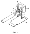
- FIG. 1 is a perspective view showing a connector according to a first embodiment of this invention along with a lamp tube in the state before the lamp tube is connected to the connector;
- FIG. 2A is a perspective view of a slider included in the connector shown in FIG. 1 ;
- FIG. 2B is a perspective view of the main part of a contact included in the connector shown in FIG. 1 ;
- FIG. 3 is a diagram for explaining the operation of the connector shown in FIG. 1 ;
- FIG. 4 is a perspective view showing a modification of the contact shown in FIG. 2B ;
- FIG. 5 is a perspective view showing another modification of the contact shown in FIG. 2B ;
- FIG. 6 is a perspective view showing still another modification of the contact shown in FIG. 2B ;
- FIG. 7 is a perspective view of a connector according to a second embodiment of this invention.
- FIG. 8 is a perspective view showing a modification of the connector shown in FIG. 7 ;
- FIGS. 9A and 9B are perspective views, as seen from different directions, respectively, of a connector according to a third embodiment of this invention.
- FIG. 10 is a diagram for explaining a floating mechanism included in the connector shown in FIGS. 9A and 9B ;
- FIG. 11 is a perspective view showing a modification of a contact included in the connector shown in FIGS. 9A and 9B ;
- FIG. 12 a perspective view showing a connector according to a fourth embodiment of this invention along with a lamp tube;
- FIG. 13 is an exploded perspective view of the connector shown in FIG. 12 ;
- FIG. 14 is a perspective view of a housing included in the connector shown in FIG. 12 ;
- FIG. 15 is a perspective view showing a modification of a contact included in the connector shown in FIG. 12 ;
- FIG. 16 is a perspective view of a connector according to a fifth embodiment of this invention.
- FIG. 17 is a perspective view showing a modification of the connector shown in FIG. 16 ;
- FIG. 18 is a side view showing an example of the shape of a floating mechanism included in the connector shown in FIG. 16 ;
- FIG. 19A is a perspective view showing a connector according to a sixth embodiment of this invention along with a lamp tube in the state before the lamp tube is connected to the connector;
- FIG. 19B is a perspective view in the state where the lamp tube is connected to the connector shown in FIG. 19A ;
- FIG. 20A is a plan view showing the connector shown in FIGS. 19A and 19B along with the lamp tube in the state before the lamp tube is connected to the connector;
- FIG. 20B is a plan view showing the connector shown in FIGS. 19A and 19B along with the lamp tube in the state where the lamp tube is connected to the connector;
- FIG. 21 is a side view of the connector shown in FIGS. 19A and 19B ;
- FIG. 22 is a perspective view of a contact included in a modification of the connector shown in FIGS. 19A and 19B ;
- FIG. 23 is a perspective view showing another modification of the connector shown in FIGS. 19A and 19B in the state before a lamp tube is connected to the connector;
- FIG. 24 is a perspective view showing still another modification of the connector shown in FIGS. 19A and 19B in the state before a lamp tube is connected to the connector;
- FIG. 25 is a perspective view of a connector according to a seventh embodiment of this invention.
- FIG. 26 is a perspective view showing a connector according to an eighth embodiment of this invention along with a lamp tube;
- FIG. 27 is a rear view of the connector shown in FIG. 26 ;
- FIG. 28 is a perspective view of a connector according to a ninth embodiment of this invention in the state where a lamp tube is connected to the connector;
- FIG. 29 is an exploded perspective view of the connector shown in FIG. 28 ;
- FIG. 30 is a perspective view showing a modification of the connector shown in FIG. 28 ;
- FIG. 31 is a perspective view showing another modification of the connector shown in FIG. 28 .
- the lamp tube connector is used for connecting, as a connection object, a fluorescent lamp tube such as a cold cathode-ray tube having lead wires.
- the lamp tube connector comprises an insulating slider 2 having a pair of projections, i.e. rotation shafts (only one of which is shown) 1 , and a conductive contact 3 combined with the slider 2 .
- the contact 3 comprises a pair of contact pieces or contact portions 5 for connection to a lead wire 4 of a lamp tube as a connection object, a pair of pressing portions 6 connected to the contact portions 5 , respectively, a rotation shaft receiving portion 8 having a pair of shaft holes 7 rotatably receiving the rotation shafts 1 , respectively, and a board connecting portion 9 as a terminal portion for connection to a board.
- the rotation shaft receiving portion 8 has a multi-sided structure with at least one corner.
- the rotation shaft receiving portion 8 has two corners 8 a and 8 b .
- a flexible link portion 10 is provided between at least one side, herein a side between the two corners 8 a and 8 b , of the rotation shaft receiving portion 8 and the board connecting portion 9 .
- the link portion 10 is formed somewhat wider only in the vicinity of the rotation shaft receiving portion 8 .
- the link portion 10 serves as a floating mechanism as will be described later.
- engaging portions 11 of the slider 2 press the pressing portions 6 of the contact 3 by rotating the slider 2 about the rotation shafts 1 .
- This causes the contact portions 5 to move in mutually opposite directions perpendicular to the rotation plane of the slider 2 so as to be connected to the lead wire 4 .
- a material of the slider 2 is not particularly limited and may be a metal.
- the contact 3 movably holds the slider 2 .
- the movement of the slider 2 causes the engaging portions 11 to press the pressing portions 6 of the contact 3 , thereby displacing the contact portions 5 .
- the lead wire 4 of the lamp tube and the contact 3 are connected together.
- the slider 2 operates the pressing portions 6 of the contact 3 depending on its movement to thereby displace the contact portions 5 , the assembility of a connection object such as a lamp tube is excellent and its replacement operation can also be facilitated.
- the contact portions 5 are given floatability with respect to the board connecting portion 9 through the link portion 10 , it is possible to reduce a stress of a connection object in the state where the connection object is kept in contact with the contact portions 5 .
- the lamp tube connector shown in FIGS. 1 to 2B can be variously modified in the configuration relating to the contact portions 5 of the contact 3 and the rotation shafts 1 of the slider 2 , as will be described hereinbelow.
- a rotation shaft receiving portion 8 at a position adjacent to contact portions 5 is formed with a link portion 10 having a relatively narrow constant width.
- a bottom plate 17 is provided between contact portions 5 and a link portion 10 and formed with a pair of guide plates 16 and these guide plates 16 are formed with shaft holes 7 for receiving rotation shafts of a slider.
- a bottom plate 17 is provided at a position opposite to a link portion 10 with respect to contact portions 5 interposed therebetween and is formed with a pair of guide plates 16 and these guide plates 16 are formed with shaft holes 7 for receiving rotation shafts of a slider.
- the lamp tube connector shown in FIG. 7 also comprises a slider 2 and a contact 3 combined with the slider 2 .
- the slider 2 has slide shafts 1 a .
- the contact 3 comprises contact portions 5 for connection to a lead wire of a lamp tube, pressing portions 6 adapted to be displaced by the slider 2 , and a board connecting portion 9 (see FIGS. 16 and 17 ).
- a shaft receiving portion 81 comprises a bottom plate 17 provided between the contact portions 5 and a link portion 10 and a pair of guide plates 16 formed integrally with the bottom plate 17 and is formed with slide holes 7 a each elongated in the front-rear direction and receiving the slide shafts 1 a , respectively.
- the slider 2 With the slide shafts 1 a being inserted into the slide holes 7 a , the slider 2 is slidably held by the shaft receiving portion 81 .
- the slide shafts 1 a and the slide holes 7 a cooperatively serve as a guide mechanism for guiding the slider 2 in a predetermined direction, for example, in a straight or curved line.
- the contact portions 5 are displaced in mutually opposite lateral directions so as to be connected to the lead wire of the lamp tube.
- the shaft receiving portion 81 has a multi-sided structure with at least one corner.
- the shaft receiving portion 81 has two corners 81 a and 81 b .
- the flexible link portion 10 is provided between at least one side, herein a side between the two corners 81 a and 81 b , of the shaft receiving portion 81 and the board connecting portion 9 .
- FIG. 8 shows a modification of the lamp tube connector shown in FIG. 7 .
- slide holes 7 b are each elongated in the up-down direction.
- contact portions 5 are displaced in mutually opposite lateral directions so as to be connected to a lead wire of a lamp tube.
- FIGS. 9A and 9B a description will be given of a lamp tube connector according to a third embodiment of this invention. Also in this lamp tube connector, the same reference symbols are assigned to the same or corresponding portions.
- a slider 2 and a contact 3 are incorporated in a housing 12 .
- the housing 12 is press-fitted or locked onto a board connecting portion 9 of the contact 3 so as to be held.
- Contact portions 5 of the contact 3 and the slider 2 have floatability with respect to the board connecting portion 9 of the contact 3 and the housing 12 .
- a flexible link portion 10 is connected between the contact portions 5 of the contact 3 and rotation shafts 1 or slide shafts 1 a of the slider 2 , and the board connecting portion 9 .
- the contact portions 5 of the contact 3 and the slider 2 have floatability with respect to the board connecting portion 9 of the contact 3 so as to be freely movable three-dimensionally.
- FIG. 11 shows a modification of the contact 3 .
- the contact 3 shown in FIG. 11 has a pair of link portions 10 between a rotation shaft receiving portion 8 and a board connecting portion 9 .
- FIGS. 12 to 14 a description will be given of a lamp tube connector according to a fourth embodiment of this invention. Also in this lamp tube connector, the same reference symbols are assigned to the same or corresponding portions.
- the lamp tube connector shown in FIGS. 12 to 14 comprises a slider 2 having recesses 2 a serving as shaft holes, a contact 3 having contact portions 5 for connection to a lead wire of a lamp tube, pressing portions 6 adapted to displace the contact portions 5 by movement of the slider 2 , and a board connecting portion 9 , and a housing 12 having projections, i.e. rotation shafts 13 , rotatably fitted into the recesses 2 a . With the rotation shafts 13 being fitted into the recesses 2 a , the slider 2 is rotatably held by the housing 12 .
- a link portion 10 allows the contact portions 5 , the pressing portions 6 , the slider 2 , and the housing 12 to have floatability with respect to the board connecting portion 9 .
- a contact 3 shown in FIG. 15 may be used.
- a holding portion 14 for holding a housing 12 is formed separately from a board connecting portion 9 .
- projections 15 of the holding portion 14 are press-fitted or locked into the housing 12 , thereby holding the housing 12 .
- FIG. 16 a description will be given of a lamp tube connector according to a fifth embodiment of this invention. Also in this lamp tube connector, the same reference symbols are assigned to the same or corresponding portions.
- the lamp tube connector shown in FIG. 16 also comprises a slider 2 , a contact 3 combined with the slider 2 , and a housing 12 accommodating them.
- the slider 2 has slide shafts as denoted by symbol 1 a in FIGS. 7 and 8 .
- the contact 3 comprises contact portions 5 for connection to a lead wire of a lamp tube, pressing portions 6 adapted to be displaced by the slider 2 , and a board connecting portion 9 .
- the housing 12 is formed with slide holes 12 a each elongated in the front-rear direction and receiving the slide shafts, respectively. With the slide shafts being inserted into the slide holes 12 a , the slider 2 is slidably held by the housing 12 . That is, part of the housing 12 serves as a slide shaft receiving portion.
- the contact portions 5 are displaced in mutually opposite lateral directions so as to be connected to the lead wire of the lamp tube.
- FIG. 17 shows a modification of the lamp tube connector shown in FIG. 16 .
- a housing 12 is formed with slide holes 12 b each elongated in the up-down direction and receiving slide shafts of a slider 2 , respectively.
- slide holes 12 b each elongated in the up-down direction and receiving slide shafts of a slider 2 , respectively.
- FIG. 18 shows an example of the shape of a link portion 10 forming a floating mechanism. It is preferable to increase the floating amount or enhance the floatability by forming the link portion 10 into a zigzag shape as illustrated in the figure.
- the contact portions 5 are in a natural state and define therebetween a gap wider than the outer diameter of the lead wire 4 of the lamp tube. Accordingly, the lead wire 4 can be placed between the contact portions 5 with no resistance when assembling the lamp tube and, thus, there is obtained an effect of making it easy to assemble the lamp tube. Further, since the contact of the contact portions 5 with the lead wire 4 of the lamp tube can be released relatively easily by releasing the slider 2 , there is also obtained an effect of making it easy to replace the lamp tube. Accordingly, it is possible to reduce the number of working processes for assembling and replacing the lamp tube.
- the contact portions 5 and the slider 2 have the floatability with respect to the board connecting portion 9 of the contact 3 and, therefore, there is obtained an effect of reducing a stress of the lead wire 4 of the lamp tube while the contact is maintained.
- any of the lamp tube connectors described with reference to FIGS. 1 to 18 is configured such that the engaging portions 11 of the slider 2 press the pressing portions 6 of the contact 3 to displace the contact portions 5 , thereby connecting the contact portions 5 to the lead wire 4 of the lamp tube.
- the contact portions 5 are in a natural state and define therebetween a gap wider than the outer diameter of the lead wire 4 of the lamp tube. Accordingly, the lead wire 4 of the lamp tube can be disposed between the contact portions 5 with no resistance and, thus, the assembility of the lamp tube is excellent.
- the contact portions 5 are restored to the natural state by an elastic restoring force of the contact 3 to release the contact with the lead wire 4 of the lamp tube. Therefore, it is possible to easily carry out a replacement operation of the lamp tube.
- the contact portions 5 have the floatability with respect to the board connecting portion 9 of the contact 3 and, therefore, it is possible to reduce a stress of the lead wire 4 of the lamp tube in the state where the contact is maintained.
- FIGS. 19A to 21 a description will be given of a lamp tube connector according to a sixth embodiment of this invention. Also in this lamp tube connector, the same reference symbols are assigned to the same or corresponding portions.
- the lamp tube connector shown in FIGS. 19A to 21 also comprises a slider 2 and a contact 3 combined with the slider 2 .
- the contact 3 has a pair of guide plates 16 facing each other with contact portions 5 and pressing portions 6 interposed therebetween and a bottom plate 17 connected between the guide plates 16 .
- the bottom plate 17 is connected to a board connecting portion 9 through a link portion 10 .
- the guide plates 16 rotatably (or pivotally) support rotation shafts 1 a of the slider 2 .
- the rotation of the slider 2 is guided by a guide mechanism comprising arc-shaped guide holes 18 of the guide plates 16 and guide projections 19 of the slider 2 inserted into the guide holes 18 , respectively.
- the slider 2 presses the pressing portions 6 of the contact 3 to displace the contact portions 5 in mutually opposite directions away from each other, i.e. to increase a gap between the contact portions 5 , thereby facilitating insertion of a lead wire 4 of the lamp tube between the contact portions 5 .
- FIG. 22 shows a contact used in a modification of the lamp tube connector shown in FIGS. 19A to 21 . As illustrated, a plurality of link portions 10 may be provided.
- FIG. 23 shows another modification of the lamp tube connector shown in FIGS. 19A to 21 . Also in this lamp tube connector, the same reference symbols are assigned to the same or corresponding portions.
- This lamp tube connector has substantially the same configuration and function as those of the lamp tube connector shown in FIG. 7 except that a slider 2 displaces contact portions of a contact 3 in mutually opposite directions away from a lead wire of a lamp tube.
- FIG. 24 shows still another modification of the lamp tube connector shown in FIGS. 19A to 21 . Also in this lamp tube connector, the same reference symbols are assigned to the same or corresponding portions.
- This lamp tube connector has substantially the same configuration and function as those of the lamp tube connector shown in FIG. 8 except that a slider 2 displaces contact portions of a contact 3 in mutually opposite directions away from a lead wire of a lamp tube.
- FIG. 25 a description will be given of a lamp tube connector according to a seventh embodiment of this invention. Also in this lamp tube connector, the same reference symbols are assigned to the same or corresponding portions.
- the lamp tube connector shown in FIG. 25 also comprises a slider 2 and a contact 3 combined with the slider 2 .
- a pair of side plates 9 a are fixedly connected to a board connecting portion 9 of the contact 3 .
- the slider 2 is disposed between the side plates 9 a .
- Rotation shafts 1 a of the slider 2 are rotatably supported by the side plates 9 a , respectively.
- the rotation of the slider 2 is guided by a guide mechanism comprising arc-shaped guide holes 18 of the contact 3 and guide projections 19 of the slider 2 inserted into the guide holes 18 , respectively.
- the board connecting portion 9 is connected to a bottom plate 17 through a link portion 10 .
- FIGS. 26 and 27 a description will be given of a lamp tube connector according to an eighth embodiment of this invention. Also in this lamp tube connector, the same reference symbols are assigned to the same or corresponding portions.
- a housing 12 is press-fitted or locked onto a board connecting portion 9 of a contact 3 so as to be held.
- This lamp tube connector has substantially the same configuration and function as those of the lamp tube connector shown in FIGS. 9A and 9B except that a slider 2 displaces contact portions of the contact 3 in mutually opposite directions away from a lead wire 4 of a lamp tube.
- FIGS. 28 and 29 show a lamp tube connector according to a ninth embodiment of this invention. Also in this lamp tube connector, the same reference symbols are assigned to the same or corresponding portions.
- a housing 12 has holding grooves 12 c .
- Holding portions 14 of a contact 3 are press-fitted or locked into the holding grooves 12 c , so that the housing 12 is held by the contact 3 .
- a slider 2 has rotation shafts 1 a . By fitting the rotation shafts 1 a into rotation shaft receiving portions 12 d of the housing 12 , the slider 2 is rotatably supported by the housing 12 using the rotation shafts 1 a as fulcrums.
- This lamp tube connector has substantially the same function as that of the lamp tube connector shown in FIG. 13 except that the slider 2 displaces contact portions of the contact 3 in mutually opposite directions away from a lead wire of a lamp tube.
- FIG. 30 shows a modification of the lamp tube connector shown in FIGS. 28 and 29 . Also in this lamp tube connector, the same reference symbols are assigned to the same or corresponding portions.
- This lamp tube connector has substantially the same configuration and function as those of the lamp tube connector shown in FIG. 16 except that a slider 2 displaces contact portions of a contact 3 in mutually opposite directions away from a lead wire of a lamp tube.
- FIG. 31 shows another modification of the lamp tube connector shown in FIGS. 28 and 29 . Also in this lamp tube connector, the same reference symbols are assigned to the same or corresponding portions.
- This lamp tube connector has substantially the same configuration and function as those of the lamp tube connector shown in FIG. 17 except that a slider 2 displaces contact portions of a contact 3 in mutually opposite directions away from a lead wire of a lamp tube.
- the contact portions 5 can ensure sufficient contact with the lead wire 4 of the lamp tube in a natural state, while, when the slider 2 presses the pressing portions 6 of the contact 3 to displace the contact portions 5 in mutually opposite directions away from each other, the contact portions 5 form therebetween a gap wider than the outer diameter of the lead wire 4 of the lamp tube. Accordingly, the lead wire 4 can be disposed between the contact portions 5 with no resistance when assembling the lamp tube and, thus, the assembility of the lamp tube is excellent.
- the contact portions 5 of the contact 3 have the floatability with respect to the board connecting portion 9 of the contact 3 while maintaining the contact with the lead wire 4 of the lamp tube and, therefore, it is possible to reduce a stress of the lead wire 4 of the lamp tube in the state where the contact is maintained.
- the combination of the rotation shafts 1 or 13 and the shaft holes 7 or 2 a which serves as the rotation axis, or the combination of the slide shafts 1 a and the slide holes 7 a , 7 b , 12 a , or 12 b , which serves as the slide axis, is provided between the slider and one of the housing and the contact.
- it may be provided between a slider and each of a housing and a contact so that the slider is rotatably or slidably held by both the housing and the contact.
Landscapes
- Fastening Of Light Sources Or Lamp Holders (AREA)
- Connecting Device With Holders (AREA)
Abstract
Description
Claims (24)
Applications Claiming Priority (4)
| Application Number | Priority Date | Filing Date | Title |
|---|---|---|---|
| JP2006188700 | 2006-07-07 | ||
| JP2006-188700 | 2006-07-07 | ||
| JP2006211326A JP4738275B2 (en) | 2006-07-07 | 2006-08-02 | Lamp tube connector |
| JP2006-211326 | 2006-08-02 |
Publications (2)
| Publication Number | Publication Date |
|---|---|
| US20080009170A1 US20080009170A1 (en) | 2008-01-10 |
| US7503786B2 true US7503786B2 (en) | 2009-03-17 |
Family
ID=38919606
Family Applications (1)
| Application Number | Title | Priority Date | Filing Date |
|---|---|---|---|
| US11/810,912 Expired - Fee Related US7503786B2 (en) | 2006-07-07 | 2007-06-07 | Connecting member and connector each having a slider adapted to displace contact portions |
Country Status (5)
| Country | Link |
|---|---|
| US (1) | US7503786B2 (en) |
| JP (1) | JP4738275B2 (en) |
| KR (2) | KR20080005079A (en) |
| CN (1) | CN101677169B (en) |
| TW (1) | TWI335697B (en) |
Cited By (42)
| Publication number | Priority date | Publication date | Assignee | Title |
|---|---|---|---|---|
| US20080160816A1 (en) * | 2007-01-03 | 2008-07-03 | Cho Joo-Woan | Lamp socket, light supply assembly having the same and display device having the same |
| US20100255685A1 (en) * | 2009-04-07 | 2010-10-07 | Japan Aviation Electronics Industry, Limited | Connector |
| US20100267263A1 (en) * | 2009-04-16 | 2010-10-21 | Kim Jung-Ki | Lamp Socket and Display Device Having the Same |
| US20110014806A1 (en) * | 2008-03-13 | 2011-01-20 | Sharp Kabushiki Kaisha | Lamp connector, backlight device and liquid crystal display device |
| US20110171854A1 (en) * | 2010-01-12 | 2011-07-14 | Japan Aviation Electronics Industry, Limited | Connector |
| US20110306220A1 (en) * | 2010-06-14 | 2011-12-15 | Hon Hai Precision Industry Co., Ltd. | Lamp socket having board supporting means |
| DE102010032837A1 (en) * | 2010-07-30 | 2012-03-01 | Dieter Mayer | Locking washer i.e. circlip, for guide bush of e.g. halogen reflector lamp, has retaining spring whose detent legs are connected with lamp in form- and force-fit manner, and nose structure formed at two ends of locking washer legs |
| US20120231669A1 (en) * | 2011-03-11 | 2012-09-13 | Sony Ericsson Mobile Communications Ab | Circuit board connector and connecting method of circuit board |
| US20130065410A1 (en) * | 2010-03-12 | 2013-03-14 | Detlef NEHM | Plug-type connector |
| US9149575B2 (en) | 2010-01-19 | 2015-10-06 | Medimop Medical Projects Ltd. | Needle assembly for drug pump |
| US9166313B2 (en) * | 2013-04-30 | 2015-10-20 | Medimop Medical Projects | Power supply contact for installation of printed circuit board |
| US9173997B2 (en) | 2007-10-02 | 2015-11-03 | Medimop Medical Projects Ltd. | External drug pump |
| USD747799S1 (en) | 2011-03-22 | 2016-01-19 | Medimop Medical Projects Ltd. | Cartridge |
| US9259532B2 (en) | 2010-01-19 | 2016-02-16 | Medimop Medical Projects Ltd. | Cartridge interface assembly |
| US9345836B2 (en) | 2007-10-02 | 2016-05-24 | Medimop Medical Projects Ltd. | Disengagement resistant telescoping assembly and unidirectional method of assembly for such |
| US9393365B2 (en) | 2012-03-26 | 2016-07-19 | Medimop Medical Projects Ltd. | Fail safe point protector for needle safety flap |
| US20160240970A1 (en) * | 2015-02-17 | 2016-08-18 | Switchlab Inc. | Wire connection terminal holding structure |
| US9421323B2 (en) | 2013-01-03 | 2016-08-23 | Medimop Medical Projects Ltd. | Door and doorstop for portable one use drug delivery apparatus |
| US9452261B2 (en) | 2010-05-10 | 2016-09-27 | Medimop Medical Projects Ltd. | Low volume accurate injector |
| US9572926B2 (en) | 2009-09-15 | 2017-02-21 | Medimop Medical Projects Ltd. | Cartridge insertion assembly |
| US9656019B2 (en) | 2007-10-02 | 2017-05-23 | Medimop Medical Projects Ltd. | Apparatuses for securing components of a drug delivery system during transport and methods of using same |
| US9987432B2 (en) | 2015-09-22 | 2018-06-05 | West Pharma. Services IL, Ltd. | Rotation resistant friction adapter for plunger driver of drug delivery device |
| US10071198B2 (en) | 2012-11-02 | 2018-09-11 | West Pharma. Servicees IL, Ltd. | Adhesive structure for medical device |
| US10071196B2 (en) | 2012-05-15 | 2018-09-11 | West Pharma. Services IL, Ltd. | Method for selectively powering a battery-operated drug-delivery device and device therefor |
| US10086145B2 (en) | 2015-09-22 | 2018-10-02 | West Pharma Services Il, Ltd. | Rotation resistant friction adapter for plunger driver of drug delivery device |
| US10149943B2 (en) | 2015-05-29 | 2018-12-11 | West Pharma. Services IL, Ltd. | Linear rotation stabilizer for a telescoping syringe stopper driverdriving assembly |
| US10293120B2 (en) | 2015-04-10 | 2019-05-21 | West Pharma. Services IL, Ltd. | Redundant injection device status indication |
| US10376647B2 (en) | 2016-03-18 | 2019-08-13 | West Pharma. Services IL, Ltd. | Anti-rotation mechanism for telescopic screw assembly |
| US10420880B2 (en) | 2007-10-02 | 2019-09-24 | West Pharma. Services IL, Ltd. | Key for securing components of a drug delivery system during assembly and/or transport and methods of using same |
| US11167086B2 (en) | 2008-09-15 | 2021-11-09 | West Pharma. Services IL, Ltd. | Stabilized pen injector |
| US11311674B2 (en) | 2016-01-21 | 2022-04-26 | West Pharma. Services IL, Ltd. | Medicament delivery device comprising a visual indicator |
| US11318254B2 (en) | 2015-10-09 | 2022-05-03 | West Pharma. Services IL, Ltd. | Injector needle cap remover |
| US11338090B2 (en) | 2016-08-01 | 2022-05-24 | West Pharma. Services IL, Ltd. | Anti-rotation cartridge pin |
| US11364337B2 (en) | 2016-01-21 | 2022-06-21 | West Pharma. Services IL, Ltd. | Force containment in an automatic injector |
| US11389597B2 (en) | 2016-03-16 | 2022-07-19 | West Pharma. Services IL, Ltd. | Staged telescopic screw assembly having different visual indicators |
| US11547802B2 (en) | 2015-10-09 | 2023-01-10 | West Pharma. Services IL, Ltd. | Angled syringe patch injector |
| US11672904B2 (en) | 2016-01-21 | 2023-06-13 | West Pharma. Services IL, Ltd. | Needle insertion and retraction mechanism |
| US11730892B2 (en) | 2016-08-01 | 2023-08-22 | West Pharma. Services IL, Ltd. | Partial door closure prevention spring |
| US11819673B2 (en) | 2016-06-02 | 2023-11-21 | West Pharma. Services, IL, Ltd. | Three position needle retraction |
| US11819666B2 (en) | 2017-05-30 | 2023-11-21 | West Pharma. Services IL, Ltd. | Modular drive train for wearable injector |
| US11857767B2 (en) | 2017-12-22 | 2024-01-02 | West Pharma. Services IL, Ltd. | Injector usable with different dimension cartridges |
| US11931552B2 (en) | 2015-06-04 | 2024-03-19 | West Pharma Services Il, Ltd. | Cartridge insertion for drug delivery device |
Families Citing this family (10)
| Publication number | Priority date | Publication date | Assignee | Title |
|---|---|---|---|---|
| EP2012176A1 (en) * | 2007-07-02 | 2009-01-07 | Heesung Electronics Co., Ltd. | Power connection apparatus of direct type backlight unit |
| JP2009059476A (en) * | 2007-08-29 | 2009-03-19 | Smk Corp | Socket for fluorescent lamp |
| CN101965480A (en) * | 2008-03-12 | 2011-02-02 | 夏普株式会社 | Lighting device, display device and television receiver |
| JP5172471B2 (en) * | 2008-04-04 | 2013-03-27 | 日本圧着端子製造株式会社 | Electrical connector and liquid crystal display device including the same |
| TWI397752B (en) * | 2009-12-31 | 2013-06-01 | Au Optronics Corp | Backlight module with an improvement socket to fix a lamp tube and lcd using the same |
| JP5440800B2 (en) * | 2010-12-29 | 2014-03-12 | 東芝ライテック株式会社 | socket |
| EP2498341A1 (en) * | 2011-03-11 | 2012-09-12 | Sony Ericsson Mobile Communications AB | Circuit board connector and connecting method of circuit board |
| DE102011085160A1 (en) * | 2011-10-25 | 2013-04-25 | Robert Bosch Gmbh | Electrically conductive contact element |
| DE202015104735U1 (en) * | 2015-09-07 | 2016-12-08 | Weidmüller Interface GmbH & Co. KG | Fixing pin for fixing a contact element in a plug housing a plug-in arrangement |
| JP6543284B2 (en) * | 2017-02-10 | 2019-07-10 | タイコエレクトロニクスジャパン合同会社 | Female contact and mating structure of contact |
Citations (11)
| Publication number | Priority date | Publication date | Assignee | Title |
|---|---|---|---|---|
| US3541492A (en) * | 1968-08-05 | 1970-11-17 | Benjamin Electric Ltd The | Heat sinks for electric lamps |
| US5340327A (en) * | 1991-04-23 | 1994-08-23 | Kabushiki Kaisha Denkosha | Sockets for discharge lamp |
| JPH10289610A (en) | 1997-04-16 | 1998-10-27 | Japan Aviation Electron Ind Ltd | Back light socket for liquid crystal |
| JP2001110535A (en) | 1999-10-12 | 2001-04-20 | Kyouwa Device:Kk | Fluorescent lamp socket |
| JP2002367422A (en) | 2001-06-07 | 2002-12-20 | Japan Aviation Electronics Industry Ltd | Backlight assembly |
| JP2003257570A (en) | 2001-12-27 | 2003-09-12 | Union Machinery Co Ltd | Lamp holder |
| JP2005183011A (en) | 2003-12-16 | 2005-07-07 | Avenir Electronics International Co Ltd | Backlight connection device for liquid crystal |
| JP2005259370A (en) | 2004-03-09 | 2005-09-22 | Avenir Electronics International Co Ltd | Connector device for fluorescent tube |
| JP2007165208A (en) | 2005-12-16 | 2007-06-28 | Nippon Tanshi Kk | Connector for cold-cathode tube |
| JP2007323924A (en) | 2006-05-31 | 2007-12-13 | Avenir Electronics International Co Ltd | Connector for fluorescent tube, and mounting method of fluorescent tube |
| JP2007335178A (en) | 2006-06-14 | 2007-12-27 | Avenir Electronics International Co Ltd | Connector for fluorescent tubes, and mounting method of fluorescent tube |
-
2006
- 2006-08-02 JP JP2006211326A patent/JP4738275B2/en not_active Expired - Fee Related
-
2007
- 2007-06-07 US US11/810,912 patent/US7503786B2/en not_active Expired - Fee Related
- 2007-06-29 KR KR1020070065292A patent/KR20080005079A/en not_active Application Discontinuation
- 2007-07-02 CN CN2009102046649A patent/CN101677169B/en not_active Expired - Fee Related
- 2007-07-06 TW TW096124577A patent/TWI335697B/en not_active IP Right Cessation
-
2009
- 2009-02-27 KR KR1020090016792A patent/KR101065510B1/en not_active IP Right Cessation
Patent Citations (12)
| Publication number | Priority date | Publication date | Assignee | Title |
|---|---|---|---|---|
| US3541492A (en) * | 1968-08-05 | 1970-11-17 | Benjamin Electric Ltd The | Heat sinks for electric lamps |
| US5340327A (en) * | 1991-04-23 | 1994-08-23 | Kabushiki Kaisha Denkosha | Sockets for discharge lamp |
| JPH10289610A (en) | 1997-04-16 | 1998-10-27 | Japan Aviation Electron Ind Ltd | Back light socket for liquid crystal |
| US5886758A (en) | 1997-04-16 | 1999-03-23 | Japan Aviation Electronics Industry | Liquid crystal backlight socket |
| JP2001110535A (en) | 1999-10-12 | 2001-04-20 | Kyouwa Device:Kk | Fluorescent lamp socket |
| JP2002367422A (en) | 2001-06-07 | 2002-12-20 | Japan Aviation Electronics Industry Ltd | Backlight assembly |
| JP2003257570A (en) | 2001-12-27 | 2003-09-12 | Union Machinery Co Ltd | Lamp holder |
| JP2005183011A (en) | 2003-12-16 | 2005-07-07 | Avenir Electronics International Co Ltd | Backlight connection device for liquid crystal |
| JP2005259370A (en) | 2004-03-09 | 2005-09-22 | Avenir Electronics International Co Ltd | Connector device for fluorescent tube |
| JP2007165208A (en) | 2005-12-16 | 2007-06-28 | Nippon Tanshi Kk | Connector for cold-cathode tube |
| JP2007323924A (en) | 2006-05-31 | 2007-12-13 | Avenir Electronics International Co Ltd | Connector for fluorescent tube, and mounting method of fluorescent tube |
| JP2007335178A (en) | 2006-06-14 | 2007-12-27 | Avenir Electronics International Co Ltd | Connector for fluorescent tubes, and mounting method of fluorescent tube |
Non-Patent Citations (1)
| Title |
|---|
| Japanese Office Action dated Jun. 25, 2008. |
Cited By (67)
| Publication number | Priority date | Publication date | Assignee | Title |
|---|---|---|---|---|
| US20080160816A1 (en) * | 2007-01-03 | 2008-07-03 | Cho Joo-Woan | Lamp socket, light supply assembly having the same and display device having the same |
| US7604494B2 (en) * | 2007-01-03 | 2009-10-20 | Samsung Electronics Co., Ltd. | Lamp socket, light supply assembly having the same and display device having the same |
| US9345836B2 (en) | 2007-10-02 | 2016-05-24 | Medimop Medical Projects Ltd. | Disengagement resistant telescoping assembly and unidirectional method of assembly for such |
| US10960131B2 (en) | 2007-10-02 | 2021-03-30 | West Pharma. Services IL, Ltd. | Apparatuses for securing components of a drug delivery system during transport and methods of using same |
| US10420880B2 (en) | 2007-10-02 | 2019-09-24 | West Pharma. Services IL, Ltd. | Key for securing components of a drug delivery system during assembly and/or transport and methods of using same |
| US10350365B2 (en) | 2007-10-02 | 2019-07-16 | West Pharma. Services IL, Ltd. | External drug pump |
| US11590291B2 (en) | 2007-10-02 | 2023-02-28 | West Pharma. Services IL, Ltd. | External drug pump |
| US9656019B2 (en) | 2007-10-02 | 2017-05-23 | Medimop Medical Projects Ltd. | Apparatuses for securing components of a drug delivery system during transport and methods of using same |
| US10384017B2 (en) | 2007-10-02 | 2019-08-20 | West Pharma. Services IL, Ltd. | Anti-rotation feature for infusion pump cartridge |
| US11504481B2 (en) | 2007-10-02 | 2022-11-22 | West Pharma. Services IL, Ltd. | Anti-rotation feature for infusion pump cartridge |
| US9173997B2 (en) | 2007-10-02 | 2015-11-03 | Medimop Medical Projects Ltd. | External drug pump |
| US10413679B2 (en) | 2007-10-02 | 2019-09-17 | West Pharma. Services IL, Ltd. | External drug pump |
| US9861759B2 (en) | 2007-10-02 | 2018-01-09 | Medimop Medical Projects Ltd. | External drug pump |
| US10716890B2 (en) | 2007-10-02 | 2020-07-21 | West Pharma. Services IL, Ltd. | Method of using a key to secure components of a drug delivery system during assembly |
| US9782545B2 (en) | 2007-10-02 | 2017-10-10 | Medimop Medical Projects Ltd. | External drug pump |
| US20110014806A1 (en) * | 2008-03-13 | 2011-01-20 | Sharp Kabushiki Kaisha | Lamp connector, backlight device and liquid crystal display device |
| US11167086B2 (en) | 2008-09-15 | 2021-11-09 | West Pharma. Services IL, Ltd. | Stabilized pen injector |
| US8277240B2 (en) | 2009-04-07 | 2012-10-02 | Japan Aviation Electronics Industry, Limited | Connector for backlight and having a member restricting movement of another member |
| US20100255685A1 (en) * | 2009-04-07 | 2010-10-07 | Japan Aviation Electronics Industry, Limited | Connector |
| US20100267263A1 (en) * | 2009-04-16 | 2010-10-21 | Kim Jung-Ki | Lamp Socket and Display Device Having the Same |
| US8113859B2 (en) * | 2009-04-16 | 2012-02-14 | Samsung Electronics Co., Ltd | Lamp socket and display device having the same |
| US9572926B2 (en) | 2009-09-15 | 2017-02-21 | Medimop Medical Projects Ltd. | Cartridge insertion assembly |
| US8087947B2 (en) * | 2010-01-12 | 2012-01-03 | Japan Aviation Electronics Industry, Limited | Connector |
| US20110171854A1 (en) * | 2010-01-12 | 2011-07-14 | Japan Aviation Electronics Industry, Limited | Connector |
| US9259532B2 (en) | 2010-01-19 | 2016-02-16 | Medimop Medical Projects Ltd. | Cartridge interface assembly |
| US9149575B2 (en) | 2010-01-19 | 2015-10-06 | Medimop Medical Projects Ltd. | Needle assembly for drug pump |
| US9522234B2 (en) | 2010-01-19 | 2016-12-20 | Medimop Medical Projects Ltd. | Needle assembly for drug pump |
| US9764092B2 (en) | 2010-01-19 | 2017-09-19 | Medimop Medical Projects Ltd. | Needle assembly for drug pump |
| US9492610B2 (en) | 2010-01-19 | 2016-11-15 | MEDIMOP Projects Ltd. | Needle assembly for drug pump |
| US8790142B2 (en) * | 2010-03-12 | 2014-07-29 | Phoenix Contact Gmbh & Co. Kg | Plug-type connector |
| US20130065410A1 (en) * | 2010-03-12 | 2013-03-14 | Detlef NEHM | Plug-type connector |
| US9452261B2 (en) | 2010-05-10 | 2016-09-27 | Medimop Medical Projects Ltd. | Low volume accurate injector |
| US20110306220A1 (en) * | 2010-06-14 | 2011-12-15 | Hon Hai Precision Industry Co., Ltd. | Lamp socket having board supporting means |
| US8251710B2 (en) * | 2010-06-14 | 2012-08-28 | Hon Hai Precision Ind. Co., Ltd. | Lamp socket having board supporting means |
| DE102010032837A1 (en) * | 2010-07-30 | 2012-03-01 | Dieter Mayer | Locking washer i.e. circlip, for guide bush of e.g. halogen reflector lamp, has retaining spring whose detent legs are connected with lamp in form- and force-fit manner, and nose structure formed at two ends of locking washer legs |
| DE102010032837B4 (en) * | 2010-07-30 | 2013-03-28 | Dieter Mayer | Holder for a lamp with plug socket, in particular for halogen reflector lamps and / or LED bulbs |
| US20120231669A1 (en) * | 2011-03-11 | 2012-09-13 | Sony Ericsson Mobile Communications Ab | Circuit board connector and connecting method of circuit board |
| USD747799S1 (en) | 2011-03-22 | 2016-01-19 | Medimop Medical Projects Ltd. | Cartridge |
| US9393365B2 (en) | 2012-03-26 | 2016-07-19 | Medimop Medical Projects Ltd. | Fail safe point protector for needle safety flap |
| US9511190B2 (en) | 2012-03-26 | 2016-12-06 | Medimop Medical Projects Ltd. | Fail safe point protector for needle safety flap |
| US10071196B2 (en) | 2012-05-15 | 2018-09-11 | West Pharma. Services IL, Ltd. | Method for selectively powering a battery-operated drug-delivery device and device therefor |
| US10071198B2 (en) | 2012-11-02 | 2018-09-11 | West Pharma. Servicees IL, Ltd. | Adhesive structure for medical device |
| US9421323B2 (en) | 2013-01-03 | 2016-08-23 | Medimop Medical Projects Ltd. | Door and doorstop for portable one use drug delivery apparatus |
| US9166313B2 (en) * | 2013-04-30 | 2015-10-20 | Medimop Medical Projects | Power supply contact for installation of printed circuit board |
| US20160240970A1 (en) * | 2015-02-17 | 2016-08-18 | Switchlab Inc. | Wire connection terminal holding structure |
| US9548564B2 (en) * | 2015-02-17 | 2017-01-17 | Switchlab Inc. | Wire connection terminal holding structure |
| US10293120B2 (en) | 2015-04-10 | 2019-05-21 | West Pharma. Services IL, Ltd. | Redundant injection device status indication |
| US10758679B2 (en) | 2015-05-29 | 2020-09-01 | West Pharma. Services IL, Ltd. | Linear rotation stabilizer for a telescoping syringe stopper driverdriving assembly |
| US10149943B2 (en) | 2015-05-29 | 2018-12-11 | West Pharma. Services IL, Ltd. | Linear rotation stabilizer for a telescoping syringe stopper driverdriving assembly |
| US11931552B2 (en) | 2015-06-04 | 2024-03-19 | West Pharma Services Il, Ltd. | Cartridge insertion for drug delivery device |
| US10912891B2 (en) | 2015-09-22 | 2021-02-09 | West Pharma. Services IL, Ltd. | Rotation resistant friction adapter for plunger driver of drug delivery device |
| US9987432B2 (en) | 2015-09-22 | 2018-06-05 | West Pharma. Services IL, Ltd. | Rotation resistant friction adapter for plunger driver of drug delivery device |
| US10086145B2 (en) | 2015-09-22 | 2018-10-02 | West Pharma Services Il, Ltd. | Rotation resistant friction adapter for plunger driver of drug delivery device |
| US11724034B2 (en) | 2015-10-09 | 2023-08-15 | West Pharma. Services, IL, Ltd. | Injector system |
| US11318254B2 (en) | 2015-10-09 | 2022-05-03 | West Pharma. Services IL, Ltd. | Injector needle cap remover |
| US11759573B2 (en) | 2015-10-09 | 2023-09-19 | West Pharma. Services, IL, Ltd. | Bent fluid path add on to a prefilled reservoir |
| US11547802B2 (en) | 2015-10-09 | 2023-01-10 | West Pharma. Services IL, Ltd. | Angled syringe patch injector |
| US11364337B2 (en) | 2016-01-21 | 2022-06-21 | West Pharma. Services IL, Ltd. | Force containment in an automatic injector |
| US11311674B2 (en) | 2016-01-21 | 2022-04-26 | West Pharma. Services IL, Ltd. | Medicament delivery device comprising a visual indicator |
| US11672904B2 (en) | 2016-01-21 | 2023-06-13 | West Pharma. Services IL, Ltd. | Needle insertion and retraction mechanism |
| US11389597B2 (en) | 2016-03-16 | 2022-07-19 | West Pharma. Services IL, Ltd. | Staged telescopic screw assembly having different visual indicators |
| US10376647B2 (en) | 2016-03-18 | 2019-08-13 | West Pharma. Services IL, Ltd. | Anti-rotation mechanism for telescopic screw assembly |
| US11819673B2 (en) | 2016-06-02 | 2023-11-21 | West Pharma. Services, IL, Ltd. | Three position needle retraction |
| US11730892B2 (en) | 2016-08-01 | 2023-08-22 | West Pharma. Services IL, Ltd. | Partial door closure prevention spring |
| US11338090B2 (en) | 2016-08-01 | 2022-05-24 | West Pharma. Services IL, Ltd. | Anti-rotation cartridge pin |
| US11819666B2 (en) | 2017-05-30 | 2023-11-21 | West Pharma. Services IL, Ltd. | Modular drive train for wearable injector |
| US11857767B2 (en) | 2017-12-22 | 2024-01-02 | West Pharma. Services IL, Ltd. | Injector usable with different dimension cartridges |
Also Published As
| Publication number | Publication date |
|---|---|
| TWI335697B (en) | 2011-01-01 |
| KR101065510B1 (en) | 2011-09-19 |
| JP2008034330A (en) | 2008-02-14 |
| CN101677169A (en) | 2010-03-24 |
| KR20080005079A (en) | 2008-01-10 |
| US20080009170A1 (en) | 2008-01-10 |
| KR20090030285A (en) | 2009-03-24 |
| JP4738275B2 (en) | 2011-08-03 |
| TW200818631A (en) | 2008-04-16 |
| CN101677169B (en) | 2012-06-20 |
Similar Documents
| Publication | Publication Date | Title |
|---|---|---|
| US7503786B2 (en) | Connecting member and connector each having a slider adapted to displace contact portions | |
| US7556515B2 (en) | Connector improved in handlability of a connection object and backlight assembly using the connector | |
| EP1919041B1 (en) | Lamp socket and display device having the same | |
| US7699496B2 (en) | Fluorescent tube attaching structure | |
| US7540750B2 (en) | Electrical connector and liquid crystal display device | |
| US7530828B2 (en) | Electrical connector and liquid crystal display device | |
| US20020041155A1 (en) | Plasma display device with flexible circuit boards and connectors | |
| US20090273919A1 (en) | Backlight unit | |
| US20100151744A1 (en) | Electrical connection member adapted to bring conductive paths formed in an insulating film into pressure contact with a connection object using inclined springs | |
| JP4230513B2 (en) | Connector and backlight assembly | |
| US7393216B2 (en) | Socket contact | |
| US20070046171A1 (en) | Fluorescent tube attaching structure | |
| JP4803759B2 (en) | Lamp tube connector | |
| KR101398123B1 (en) | Lamp socket and display device having the same and lamp assembling method | |
| US7442062B2 (en) | Fluorescent tube connector device, light source device, and display | |
| US20110081795A1 (en) | Contact and connector | |
| US20130107134A1 (en) | Lighting device, display device and television receiver | |
| KR100838494B1 (en) | Backlight unit for lcd | |
| US8294349B2 (en) | Lighting device, display device and television receiver | |
| JP2009037923A (en) | Backlight device | |
| JP2009026555A (en) | Socket for cold-cathode tube |
Legal Events
| Date | Code | Title | Description |
|---|---|---|---|
| AS | Assignment |
Owner name: JAE HIROSAKI, LTD., JAPAN Free format text: ASSIGNMENT OF ASSIGNORS INTEREST;ASSIGNORS:KATO, NOBUKAZU;KUROIWA, MASAKAZU;KATO, RINTARO;AND OTHERS;REEL/FRAME:019457/0402;SIGNING DATES FROM 20070523 TO 20070529 Owner name: JAPAN AVIATION ELECTRONICS INDUSTRY, LIMITED, JAPA Free format text: ASSIGNMENT OF ASSIGNORS INTEREST;ASSIGNORS:KATO, NOBUKAZU;KUROIWA, MASAKAZU;KATO, RINTARO;AND OTHERS;REEL/FRAME:019457/0402;SIGNING DATES FROM 20070523 TO 20070529 |
|
| AS | Assignment |
Owner name: JAPAN AVIATION ELECTRONICS INDUSTRY, LIMITED, JAPA Free format text: ASSIGNMENT OF ASSIGNORS INTEREST;ASSIGNOR:JAE HIROSAKI, LTD.;REEL/FRAME:021439/0015 Effective date: 20080825 Owner name: JAPAN AVIATION ELECTRONICS INDUSTRY, LIMITED, JAPA Free format text: ASSIGNMENT OF ASSIGNORS INTEREST;ASSIGNOR:JAE HIROSAKI, LTD.;REEL/FRAME:021439/0012 Effective date: 20080825 |
|
| STCF | Information on status: patent grant |
Free format text: PATENTED CASE |
|
| FPAY | Fee payment |
Year of fee payment: 4 |
|
| FPAY | Fee payment |
Year of fee payment: 8 |
|
| FEPP | Fee payment procedure |
Free format text: MAINTENANCE FEE REMINDER MAILED (ORIGINAL EVENT CODE: REM.); ENTITY STATUS OF PATENT OWNER: LARGE ENTITY |
|
| LAPS | Lapse for failure to pay maintenance fees |
Free format text: PATENT EXPIRED FOR FAILURE TO PAY MAINTENANCE FEES (ORIGINAL EVENT CODE: EXP.); ENTITY STATUS OF PATENT OWNER: LARGE ENTITY |
|
| STCH | Information on status: patent discontinuation |
Free format text: PATENT EXPIRED DUE TO NONPAYMENT OF MAINTENANCE FEES UNDER 37 CFR 1.362 |
|
| FP | Lapsed due to failure to pay maintenance fee |
Effective date: 20210317 |