US7477852B2 - Optical receiver apparatus and method - Google Patents
Optical receiver apparatus and method Download PDFInfo
- Publication number
- US7477852B2 US7477852B2 US11/047,011 US4701105A US7477852B2 US 7477852 B2 US7477852 B2 US 7477852B2 US 4701105 A US4701105 A US 4701105A US 7477852 B2 US7477852 B2 US 7477852B2
- Authority
- US
- United States
- Prior art keywords
- modulated signals
- optical
- signal
- intensity
- amplitude
- Prior art date
- Legal status (The legal status is an assumption and is not a legal conclusion. Google has not performed a legal analysis and makes no representation as to the accuracy of the status listed.)
- Expired - Fee Related, expires
Links
Images


Classifications
-
- H—ELECTRICITY
- H04—ELECTRIC COMMUNICATION TECHNIQUE
- H04B—TRANSMISSION
- H04B10/00—Transmission systems employing electromagnetic waves other than radio-waves, e.g. infrared, visible or ultraviolet light, or employing corpuscular radiation, e.g. quantum communication
- H04B10/60—Receivers
- H04B10/66—Non-coherent receivers, e.g. using direct detection
- H04B10/67—Optical arrangements in the receiver
- H04B10/676—Optical arrangements in the receiver for all-optical demodulation of the input optical signal
- H04B10/677—Optical arrangements in the receiver for all-optical demodulation of the input optical signal for differentially modulated signal, e.g. DPSK signals
-
- H—ELECTRICITY
- H04—ELECTRIC COMMUNICATION TECHNIQUE
- H04B—TRANSMISSION
- H04B10/00—Transmission systems employing electromagnetic waves other than radio-waves, e.g. infrared, visible or ultraviolet light, or employing corpuscular radiation, e.g. quantum communication
- H04B10/60—Receivers
- H04B10/66—Non-coherent receivers, e.g. using direct detection
- H04B10/67—Optical arrangements in the receiver
- H04B10/671—Optical arrangements in the receiver for controlling the input optical signal
- H04B10/672—Optical arrangements in the receiver for controlling the input optical signal for controlling the power of the input optical signal
- H04B10/674—Optical arrangements in the receiver for controlling the input optical signal for controlling the power of the input optical signal using a variable optical attenuator
-
- H—ELECTRICITY
- H04—ELECTRIC COMMUNICATION TECHNIQUE
- H04B—TRANSMISSION
- H04B10/00—Transmission systems employing electromagnetic waves other than radio-waves, e.g. infrared, visible or ultraviolet light, or employing corpuscular radiation, e.g. quantum communication
- H04B10/60—Receivers
- H04B10/66—Non-coherent receivers, e.g. using direct detection
- H04B10/69—Electrical arrangements in the receiver
Definitions
- the present invention relates generally to optical transmission, and more particularly to methods and apparatus for receiving phase shift keyed (PSK) optical signals.
- PSK phase shift keyed
- DPSK differential phase shift keying
- OOK on/off keying
- DPSK signal transmission has also been found to be more robust to narrowband optical filtering as compared to other modulation formats. Such characteristics make DPSK modulation a desirable format for optically-routed networks that incorporate multiple optical add/drop multiplexers (OADM) or optical crossconnects (OXC).
- OADM optical add/drop multiplexers
- OXC optical crossconnects
- PSK optical receivers are typically built using an optical delay interferometer followed by a balanced photoreceiver.
- Prior art teachings suggest that optimum receiver performance is obtained if the balanced receiver is perfectly amplitude-balanced.
- OADMs or OXCs optical filter devices
- OSNR optical signal-to-noise ratio
- the present invention provides a method and apparatus for improved reception of optical PSK signals transmitted in systems employing narrowband optical filtering.
- the improved reception is achieved by converting optical PSK signals at a receiver into two intensity-modulated signals and introducing a desired amplitude imbalance between the two signals. Introduction of such an amplitude imbalance improves receiver performance for narrowband filtered PSK signals by effectively mitigating any degraded receiver performance due to the narrowband optical filtering and reducing the optical signal-to-noise ratio required for substantially error-free transmission.
- FIG. 1 is a schematic diagram of a receiver apparatus which can be used in accordance with embodiments of the invention
- FIG. 2 is a schematic diagram of an experimental optical transmission system including a receiver apparatus according to one embodiment of the invention
- FIG. 3 is a plot showing the optical spectra of a carrier suppressed return-to-zero differential phase shift keyed (CSRZ-DPSK) signal after transmission through zero, one, two and five optical add-drop multiplexers (OADMs);
- CSRZ-DPSK carrier suppressed return-to-zero differential phase shift keyed
- FIG. 4 is a plot showing the OSNR required to achieve a bit error rate (BER) of about 10 ⁇ 3 (Required OSNR) vs. photocurrent imbalance for various OADM concatenations; and
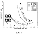
- FIG. 5 is a plot showing OSNR penalty vs. photocurrent imbalance for various OADM concatenations.
- FIG. 1 is a schematic diagram of an optical receiver apparatus 100 in accordance with aspects of the invention for receiving narrowband filtered optical PSK signals.
- “narrowband filtered” or “strongly filtered” optical signals refer to optical signals carrying information at a data rate of, for example, B gigabits/s that are optically filtered with an optical filter of a bandwidth of about B gigahertz (i.e. about one times the data rate).
- a “narrowband” optical filter having a bandwidth of 40 gigahertz would “strongly” filter a CSRZ-DPSK optical signal carrying information at 40 gigabits/s.
- the optical receiver apparatus 100 comprises an interferometer 110 for receiving PSK signals.
- the interferometer 110 is preferably a Mach-Zehnder delay interferometer (MZDI) that provides a delay of about one bit between the arms 111 A, 111 B of the interferometer 110 .
- MZDI Mach-Zehnder delay interferometer
- the interferometer 110 converts incoming PSK signals into a first and a second optical intensity-modulated signal (e.g. at the constructive and destructive output ports of the MZDI).
- the first and second optical intensity-modulated signals are output from the interferometer 110 on output ports 110 A and 110 B, respectively.
- Two photodiodes 115 A, 115 B are respectively coupled to the output ports 110 A, 110 B of the interferometer 110 .
- the photodiodes 115 A, 115 B are used to differentially detect the first and second optical intensity-modulated signals and generate electrical intensity-modulated signals (i.e. generate photocurrents representative of the first and second optical intensity-modulated signals).
- the photodiodes 115 A, 115 B are preferably identical InP waveguide PIN photodiodes.
- One or more amplitude attenuator/gain elements 120 A, 120 B, 120 C, 120 D are used to control or adjust the power (i.e. amplitude) of at least one of either the first and second optical intensity-modulated signals from the interferometer 110 , or the first and second electrical intensity-modulated signals from the photodiodes 115 A, 115 B.
- the attenuator/gain elements 120 A, 120 D can be, for example variable optical attenuators, variable optical gain device, or any device capable of controlling the power of the first and/or second optical intensity-modulated signals.
- the attenuator/gain elements 120 B, 120 C can be, for example, electrical variable gain amplifiers, variable electrical attenuators, or any device capable of controlling the power of the first and/or second electrical intensity-modulated signals.
- the attenuator/gain elements 120 A, 120 B, 120 C, 120 D are preferably used to introduce an amplitude imbalance between the first and second optical intensity-modulated signals, and/or between the first and second electrical intensity-modulated signals. It is understood that for a perfectly balanced receiver, i.e. a receiver that under ideal PSK modulation and broad optical filtering yields equal amplitudes of the first and second electrical intensity-modulated signals, a “natural” imbalance may exist between the first and second intensity-modulated signals (optical or electrical) once the received PSK signals are subject to narrowband filtering.
- the introduction of an amplitude imbalance between first and second intensity-modulated signals includes introducing an imbalance to “balanced” signals, and/or adding to or modifying any “natural” (i.e. existing) imbalance to obtain improved (e.g. optimum) receiver performance.
- introduction of the amplitude imbalance includes changing the amplitude ratio of the first and second optical intensity-modulated signals, and/or the first and second electrical intensity-modulated signals.
- the ratio of the amplitudes of the first and second electrical intensity-modulated signals By changing the ratio of the amplitudes of the first and second electrical intensity-modulated signals the natural distribution of optical energy between first and second electrical intensity-modulated signals that is imprinted by narrowband optical filtering is reshaped in a way that a receiver output signal (e.g receiver output signals 160 , 280 , discussed below) becomes better suited for detection.
- the overall opto-electronic conversion factor can be given by S A and S B , respectively.
- the opto-electronic conversion factor S A or S B is defined as the ratio of the optical signal amplitude of an optical intensity-modulated signal (e.g. at output 110 A) to the electrical signal amplitude of an electrical intensity-modulated signal (e.g. before the differential amplifier 150 , discussed below).
- a differential linear amplifier 150 or the like is preferably used to combine the first and second electrical intensity-modulated signals to generate a receiver output signal 160 representative of the received PSK signal.
- a transmitter 210 comprising two LiNbO 3 Mach-Zehnder modulators (MZMs) in series was used to generate a carrier-suppressed return-to-zero (CSRZ-DPSK) (i.e. a 67% return-to-zero DPSK signal) modulated single wavelength channel at 1550.4 nm.
- the first modulator 210 A was driven by a 21.3-GHz clock, and acted as a pulse carver, for generating 67% RZ pulses.
- By driving the second modulator 210 B at the null point data was imposed as a phase modulation.
- FEC forward error correction
- a 100-to-50-GHz optical interleaver (IL) 220 (with a 3-dB bandwidth of ⁇ 44 GHz) was used after the transmitter to provide prefiltering of the CSRZ-DPSK signal.
- a re-circulating loop 230 comprised a single 10-km span of SSMF fiber followed by a slope-matched dispersion compensating module (DCM) 235 that provided full dispersion compensation.
- the re-circulating loop 230 further comprised an OADM 240 having an IL 240 A and a de-interleaver (D-IL) 240 B connected back-to-back, which emulates a severely filtered path through an OADM node.
- An EDFA pre-amplifier 250 was used at the receiver side of the system followed by a 50-to-100-GHz D-IL 255 .
- a tunable dispersion compensator (TDC) (not shown) was used to bring the net dispersion of the CSRZ-DPSK signal to about zero.
- a receiver 257 was coupled to the re-circulating loop 230 and included a MZDI 260 with a 1-bit delay (23.4 ps) between the two arms, variable optical attenuators 265 A, 265 B, and an optical front end (OFE) 270 .
- the MZDI 260 was used to convert the incoming CSRZ-DPSK signal into first and second optical intensity-modulated signals at the two output ports 260 A, 260 B (depending on the phase difference between adjacent bits).
- maximum power appears at one output port (i.e. the “constructive” port) when there was no phase change between adjacent bits of the CSRZ-DPSK signal, and at the other port (i.e. the “destructive” port) when the phase in adjacent bits differs by ⁇ .
- the optical power levels of the first and second optical intensity-modulated signals were adjusted using the variable optical attenuators 265 A, 265 B to introduce a desired amplitude imbalance between the first and second optical intensity-modulated signals.
- the OFE 270 comprising two identical InP waveguide PIN photodiodes 270 A, 270 B followed by a differential linear amplifier 275 , was used to detect the first and second optical intensity-modulated signals and generate a receiver output signal 280 .
- the average photocurrent at both photodiodes 270 A, 270 B was monitored.
- the receiver output signal 280 was then demultiplexed from 42.7 Gb/s to 10.7 Gb/s using a commercial electronic demultiplexer 290 , and BER was measured. In loop operation, the measured BER was an average over the four 10.7 Gb/s tributaries.
- FIG. 3 shows the optical spectrum of the CSRZ-DPSK signal after zero, one, two, and five OADMs, illustrating the spectral narrowing due to filter concatenation.
- the interleavers 240 A, 240 B used in the experimental transmission system 200 of FIG. 2 were standard commercially available 10-Gb/s interleavers and third-order Gaussian filters with a 3-dB and 20-dB bandwidth of ⁇ 44 GHz and 62 GHz, respectively.
- the impact of an amplitude imbalance on strongly filtered CSRZ-DPSK was studied, the performance of the experimental transmission system 200 of FIG. 2 was assessed in terms of the optical signal-to-noise ratio (OSNR) required to achieve a target BER of 10 ⁇ 3 (i.e. the threshold for error-free operation (corrected BER of 10 ⁇ 16 or better using enhanced FEC)).
- OSNR optical signal-to-noise ratio
- ⁇ I corresponds to an emphasized signal from the constructive (destructive) port.
- emphasizing a signal can either occur naturally due to narrowband optical filtering, or intentionally due to varying ⁇ A .
- the required OSNR (OSNR Req ) (i.e. the ratio between the total signal power of the received CSRZ-DPSK signal divided by the amplified spontaneous emission (ASE) measured in 0.1 nm bandwidth) was obtained by degrading the received OSNR by loading ASE noise before the pre-amplifier 250 until the measured BER degraded to 10 ⁇ 3 .
- FIG. 4 shows the OSNR Req of the CSRZ-DPSK signal as a function of the photocurrent imbalance ( ⁇ I ) for multiple passes through the OADM 240 .
- the “No filters” curve corresponds to the case when there are no interleavers at the transmitter or at the receiver (sometimes referred to as the “back-to-back” case).
- the “No-Filters” curve represents performance that is obtainable under minimal optical filtering, where the OSNR Req slowly rises for both positive and negative ⁇ I .
- the “No OADM” curve corresponds to the case when the interleavers 222 , 255 at the transmitter 210 and receiver 257 are included. As the number of OADM nodes increases, the OSNR Req rises rapidly when the receiver 257 was balanced. The performance degrades even further for negative ⁇ I . Positive ⁇ I results in significantly improved receiver performance. This improvement is also evident in the electrical eye diagrams inset in FIG. 4 .
- the OSNR penalty at a BER of 10 ⁇ 3 was defined as: OSNR Req after filtering—back-to-back (No-filter) OSNR Req with perfectly balanced detection.
- the OSNR penalty is shown as a function of the photocurrent imbalance ( ⁇ I ) in FIG. 5 and is effectively minimized for positive values of ⁇ I .
Abstract
Description
βA=(S A −S B)/(S A +S B),
where βA=0 corresponds to a perfectly balanced case.
βI=(I cons −I des)/(I cons +I des),
where Icons and Ides are the average photocurrents resulting from the first and second electrical intensity-modulated signals from the
Claims (8)
Priority Applications (5)
| Application Number | Priority Date | Filing Date | Title |
|---|---|---|---|
| US11/047,011 US7477852B2 (en) | 2005-01-31 | 2005-01-31 | Optical receiver apparatus and method |
| EP06250270A EP1686709B1 (en) | 2005-01-31 | 2006-01-19 | Optical receiver apparatus and corresponding method |
| DE602006002402T DE602006002402D1 (en) | 2005-01-31 | 2006-01-19 | Optical receiver and corresponding method |
| CN200610002450XA CN1815931B (en) | 2005-01-31 | 2006-01-26 | Optical receiver apparatus and corresponding method |
| JP2006021611A JP2006217605A (en) | 2005-01-31 | 2006-01-31 | Optical receiving apparatus and method |
Applications Claiming Priority (1)
| Application Number | Priority Date | Filing Date | Title |
|---|---|---|---|
| US11/047,011 US7477852B2 (en) | 2005-01-31 | 2005-01-31 | Optical receiver apparatus and method |
Publications (2)
| Publication Number | Publication Date |
|---|---|
| US20060171720A1 US20060171720A1 (en) | 2006-08-03 |
| US7477852B2 true US7477852B2 (en) | 2009-01-13 |
Family
ID=36128253
Family Applications (1)
| Application Number | Title | Priority Date | Filing Date |
|---|---|---|---|
| US11/047,011 Expired - Fee Related US7477852B2 (en) | 2005-01-31 | 2005-01-31 | Optical receiver apparatus and method |
Country Status (5)
| Country | Link |
|---|---|
| US (1) | US7477852B2 (en) |
| EP (1) | EP1686709B1 (en) |
| JP (1) | JP2006217605A (en) |
| CN (1) | CN1815931B (en) |
| DE (1) | DE602006002402D1 (en) |
Cited By (21)
| Publication number | Priority date | Publication date | Assignee | Title |
|---|---|---|---|---|
| US20080138065A1 (en) * | 2006-08-16 | 2008-06-12 | Nec Corporation | Evaluation and adjustment method of optical receiver and optical communication system |
| US20080205886A1 (en) * | 2005-04-29 | 2008-08-28 | National Ict Australia Limited | Method and Device for In-Band Optical Performance Monitoring |
| US20080225381A1 (en) * | 2007-03-14 | 2008-09-18 | Heffner Brian L | Delay line interferometer having a stepped delay element |
| US20080226306A1 (en) * | 2007-03-14 | 2008-09-18 | Heffner Brian L | GT decoder having bandwidth control for ISI compensation |
| US20080231941A1 (en) * | 2007-03-14 | 2008-09-25 | Cristian Malouin | Optical receiver having FSR phase compensation |
| US20080232821A1 (en) * | 2007-03-22 | 2008-09-25 | Christian Malouin | Optical receiver having transfer function bandwidth selection |
| US20090116851A1 (en) * | 2007-11-05 | 2009-05-07 | Heffner Brian L | Optical Receiver Having Bandwidth Control For Intersymbol Interference Compensation |
| US20100046948A1 (en) * | 2008-08-19 | 2010-02-25 | Andrew Roman Chraplyvy | System and method for receiving high spectral efficiency optical dpsk signals |
| US20100135678A1 (en) * | 2008-11-28 | 2010-06-03 | Fujitsu Limited | Optical receiving device, optical receiving circuit, and method for receiving optical signals |
| US20100284702A1 (en) * | 2007-03-22 | 2010-11-11 | Opnext Subsystems, Inc. | Optical Receivers with Controllable Transfer Function Bandwidth and Gain Imbalance |
| US20110228280A1 (en) * | 2010-03-17 | 2011-09-22 | Lightlab Imaging, Inc. | Intensity Noise Reduction Methods and Apparatus for Interferometric Sensing and Imaging Systems |
| US20120070149A1 (en) * | 2010-09-17 | 2012-03-22 | Electronics And Telecommunications Research Institute | Coherent optical receiving apparatus and optical signal processing method |
| US20120308230A1 (en) * | 2011-05-30 | 2012-12-06 | Electronics And Telecommunications Research Institute | Method and apparatus for controlling an optical receiver having delay paths |
| US20120315049A1 (en) * | 2008-11-20 | 2012-12-13 | Telcordia Technologies, Inc. | Method and apparatus for optimized analog rf optical links |
| US20130071122A1 (en) * | 2010-06-03 | 2013-03-21 | Hitachi, Ltd. | Optical communication system, optical receiver, optical transponder, wavelength multiplexing optical communication system, wavelength multiplexing receiving device, and wavelength multiplexing optical transponder |
| US20130163986A1 (en) * | 2010-04-15 | 2013-06-27 | Oclaro Technology Limited | Electrically-adaptive dspk and (d)mpsk receivers |
| US20140140652A1 (en) * | 2012-04-13 | 2014-05-22 | California Institute Of Technology | Integrated Light Source Independent Linewidth Reduction of Lasers Using Electro-Optical Feedback Techniques |
| US20150256266A1 (en) * | 2014-03-10 | 2015-09-10 | Cisco Technology, Inc. | Common Mode Rejection Ratio Control for Coherent Optical Receivers |
| US9548878B2 (en) | 2008-03-12 | 2017-01-17 | Hypres, Inc. | Digital radio frequency transceiver system and method |
| US10243672B2 (en) * | 2016-06-30 | 2019-03-26 | Luxtera, Inc. | Method and system for waveguide delay based equalization with current and optical summing in optical communication |
| US20220149954A1 (en) * | 2019-10-31 | 2022-05-12 | Ciena Corporation | Asymmetric direct detection of optical signals |
Families Citing this family (19)
| Publication number | Priority date | Publication date | Assignee | Title |
|---|---|---|---|---|
| US7477852B2 (en) * | 2005-01-31 | 2009-01-13 | Alcatel-Lucent Usa Inc. | Optical receiver apparatus and method |
| JP4922594B2 (en) * | 2005-05-23 | 2012-04-25 | 富士通株式会社 | Optical transmitter, optical receiver, and optical communication system including them |
| US7949261B2 (en) * | 2006-04-26 | 2011-05-24 | Mintera Corporation | Partial DPSK (PDPSK) transmission systems |
| JP4489743B2 (en) * | 2006-10-04 | 2010-06-23 | 日本電信電話株式会社 | Frame synchronization method and optical signal receiving apparatus |
| US8346099B2 (en) | 2006-12-13 | 2013-01-01 | Nec Corporation | Optical reception device and optical reception method |
| JP5233115B2 (en) | 2006-12-22 | 2013-07-10 | 日本電気株式会社 | Optical receiver using DQPSK demodulation method and DQPSK demodulation method |
| JP4818142B2 (en) * | 2007-02-06 | 2011-11-16 | 富士通株式会社 | Optical receiver, control method therefor, and optical transmission system |
| JP2008219069A (en) | 2007-02-28 | 2008-09-18 | Yokogawa Electric Corp | Optical receiver and optical transmitter |
| WO2008130674A1 (en) * | 2007-04-20 | 2008-10-30 | Optium Corporation | Method and apparatus for dispersion mitigation in optical links |
| JP2008271479A (en) | 2007-04-25 | 2008-11-06 | Nec Corp | Dpsk optical receiver |
| WO2009052332A2 (en) * | 2007-10-16 | 2009-04-23 | Stratalight Communicaitons, Inc. | Balanced phase-shaped binary transmission in optical communications |
| JP5339088B2 (en) * | 2007-11-30 | 2013-11-13 | 日本電気株式会社 | Optical receiving circuit and signal processing method |
| US8032036B2 (en) | 2007-12-10 | 2011-10-04 | Verizon Patent And Licensing Inc. | DQPSK/DPSK optical receiver with tunable optical fibers |
| JP5340004B2 (en) | 2008-06-18 | 2013-11-13 | 株式会社日立製作所 | Balance compensation type optical balanced receiver and optical IQ receiver |
| US8611751B2 (en) * | 2009-02-26 | 2013-12-17 | Alcatel Lucent | System, apparatus and method for communicating data via polarization multiplexing |
| US20110052196A1 (en) * | 2009-08-27 | 2011-03-03 | Gnauck Alan H | Narrow-band DPSK apparatus, system, method |
| US20110135301A1 (en) * | 2009-12-08 | 2011-06-09 | Vello Systems, Inc. | Wavelocker for Improving Laser Wavelength Accuracy in WDM Networks |
| US8737618B2 (en) * | 2010-02-17 | 2014-05-27 | Telcordia Technologies, Inc. | Secure key distribution for optical code division multiplexed based optical encryption |
| US10333627B2 (en) * | 2017-06-26 | 2019-06-25 | Inphi Corporation | Rx delay line inteferometer tracking in closed-loop module control for communication |
Citations (28)
| Publication number | Priority date | Publication date | Assignee | Title |
|---|---|---|---|---|
| US4718121A (en) * | 1985-03-07 | 1988-01-05 | Stc Plc | Balanced coherent receiver |
| US5075793A (en) * | 1987-08-04 | 1991-12-24 | Siemens Aktiengesellschaft | Apparatus for detecting intensity-modulated light signals |
| US5115332A (en) * | 1989-07-20 | 1992-05-19 | Fujitsu Limited | Receiver for coherent optical communication |
| US5181136A (en) * | 1989-09-22 | 1993-01-19 | The University Of Ottawa | Optical homodyne DPSK receiver with optical amplifier |
| US5323258A (en) * | 1990-10-05 | 1994-06-21 | Hitachi, Ltd. | Homodyne optical receiver equipment |
| US5463461A (en) * | 1991-03-06 | 1995-10-31 | Kokusai Denshin Denwa Company, Ltd. | Coherent optical receiver having optically amplified local oscillator signal |
| US5586101A (en) * | 1995-03-01 | 1996-12-17 | Eastman Kodak Company | Magneto-optic data storage system with differential detection channels having separate gain control circuit |
| US6271959B1 (en) * | 1998-06-23 | 2001-08-07 | Nortel Networks Limited | Method and apparatus for optical frequency demodulation of an optical signal using interferometry |
| US6362911B1 (en) * | 1997-12-17 | 2002-03-26 | Electronics And Telecommunications Research Institute | Burst mode optical receiver using two amplifiers having different bandwidth |
| US6731881B2 (en) * | 1999-12-01 | 2004-05-04 | Nec Corporation | Device for transmitting and receiving optical signals |
| US6775484B1 (en) * | 1997-06-03 | 2004-08-10 | Alcatel Alsthom Compagnie Generale D'electricite | Receiver for receiving optical signals |
| US6834165B2 (en) * | 2000-06-13 | 2004-12-21 | International Business Machines Corporation | Parallel opto-electric structure for high sensitivity and wide bandwidth optical transceiver |
| US20050117915A1 (en) * | 2003-12-01 | 2005-06-02 | Tetsuya Miyazaki | Optical transmission method and system |
| US20050260000A1 (en) * | 2002-10-16 | 2005-11-24 | Jerzy Domagala | Optical receiver including a system and method of controlling gain of an optical amplifier |
| US20060140636A1 (en) * | 2002-11-29 | 2006-06-29 | Lucia Marazzi | Optical communication system |
| US20060171720A1 (en) * | 2005-01-31 | 2006-08-03 | Anjali Agarwal | Optical receiver apparatus and method |
| US7092644B2 (en) * | 2001-09-28 | 2006-08-15 | New Focus, Inc. | Optical receiver including a dual gain path amplifier system |
| US7110677B2 (en) * | 2001-09-26 | 2006-09-19 | Celight, Inc. | Method and system for optical time division multiplexed fiber communications with coherent detection |
| US7130545B2 (en) * | 2001-06-22 | 2006-10-31 | The United States Of America As Represented By The Secretary Of The Navy | High speed electro-optic clock recovery circuit |
| US7162165B2 (en) * | 2002-08-02 | 2007-01-09 | Agilent Technologies, Inc. | Kalman filter assembly intensity noise subtraction for optical heterodyne receivers |
| US7184672B2 (en) * | 2002-09-25 | 2007-02-27 | Nortel Networks Limited | Analogue maintenance detection |
| US7200344B1 (en) * | 2001-05-10 | 2007-04-03 | Fujitsu Limited | Receiver and method for a multichannel optical communication system |
| US7209670B2 (en) * | 2003-04-29 | 2007-04-24 | Nortel Networks Limited | Polarization diversity receiver for optical transmission system |
| US7233430B2 (en) * | 2004-12-23 | 2007-06-19 | Massachusetts Institute Of Technology | Multi-channel DPSK receiver |
| US7266307B2 (en) * | 2002-02-01 | 2007-09-04 | Isaac Shpantzer | Method and apparatus for pulse generation and adaptive pulse generation for optical communications |
| US20070206898A1 (en) * | 2006-01-03 | 2007-09-06 | Nec Laboratories America | Optical equalization filtering of dwdm channels |
| US7333732B2 (en) * | 2004-12-30 | 2008-02-19 | Tyco Telecommunications (Us) Inc. | Optical receiver |
| US7373091B2 (en) * | 2003-09-25 | 2008-05-13 | Lucent Technologies Inc. | Multicasting optical switch fabric and method of detection based on novel heterodyne receiver |
Family Cites Families (1)
| Publication number | Priority date | Publication date | Assignee | Title |
|---|---|---|---|---|
| JP4523588B2 (en) * | 2004-05-13 | 2010-08-11 | 三菱電機株式会社 | Optical signal quality monitoring device |
-
2005
- 2005-01-31 US US11/047,011 patent/US7477852B2/en not_active Expired - Fee Related
-
2006
- 2006-01-19 DE DE602006002402T patent/DE602006002402D1/en active Active
- 2006-01-19 EP EP06250270A patent/EP1686709B1/en not_active Expired - Fee Related
- 2006-01-26 CN CN200610002450XA patent/CN1815931B/en not_active Expired - Fee Related
- 2006-01-31 JP JP2006021611A patent/JP2006217605A/en not_active Ceased
Patent Citations (28)
| Publication number | Priority date | Publication date | Assignee | Title |
|---|---|---|---|---|
| US4718121A (en) * | 1985-03-07 | 1988-01-05 | Stc Plc | Balanced coherent receiver |
| US5075793A (en) * | 1987-08-04 | 1991-12-24 | Siemens Aktiengesellschaft | Apparatus for detecting intensity-modulated light signals |
| US5115332A (en) * | 1989-07-20 | 1992-05-19 | Fujitsu Limited | Receiver for coherent optical communication |
| US5181136A (en) * | 1989-09-22 | 1993-01-19 | The University Of Ottawa | Optical homodyne DPSK receiver with optical amplifier |
| US5323258A (en) * | 1990-10-05 | 1994-06-21 | Hitachi, Ltd. | Homodyne optical receiver equipment |
| US5463461A (en) * | 1991-03-06 | 1995-10-31 | Kokusai Denshin Denwa Company, Ltd. | Coherent optical receiver having optically amplified local oscillator signal |
| US5586101A (en) * | 1995-03-01 | 1996-12-17 | Eastman Kodak Company | Magneto-optic data storage system with differential detection channels having separate gain control circuit |
| US6775484B1 (en) * | 1997-06-03 | 2004-08-10 | Alcatel Alsthom Compagnie Generale D'electricite | Receiver for receiving optical signals |
| US6362911B1 (en) * | 1997-12-17 | 2002-03-26 | Electronics And Telecommunications Research Institute | Burst mode optical receiver using two amplifiers having different bandwidth |
| US6271959B1 (en) * | 1998-06-23 | 2001-08-07 | Nortel Networks Limited | Method and apparatus for optical frequency demodulation of an optical signal using interferometry |
| US6731881B2 (en) * | 1999-12-01 | 2004-05-04 | Nec Corporation | Device for transmitting and receiving optical signals |
| US6834165B2 (en) * | 2000-06-13 | 2004-12-21 | International Business Machines Corporation | Parallel opto-electric structure for high sensitivity and wide bandwidth optical transceiver |
| US7200344B1 (en) * | 2001-05-10 | 2007-04-03 | Fujitsu Limited | Receiver and method for a multichannel optical communication system |
| US7130545B2 (en) * | 2001-06-22 | 2006-10-31 | The United States Of America As Represented By The Secretary Of The Navy | High speed electro-optic clock recovery circuit |
| US7110677B2 (en) * | 2001-09-26 | 2006-09-19 | Celight, Inc. | Method and system for optical time division multiplexed fiber communications with coherent detection |
| US7092644B2 (en) * | 2001-09-28 | 2006-08-15 | New Focus, Inc. | Optical receiver including a dual gain path amplifier system |
| US7266307B2 (en) * | 2002-02-01 | 2007-09-04 | Isaac Shpantzer | Method and apparatus for pulse generation and adaptive pulse generation for optical communications |
| US7162165B2 (en) * | 2002-08-02 | 2007-01-09 | Agilent Technologies, Inc. | Kalman filter assembly intensity noise subtraction for optical heterodyne receivers |
| US7184672B2 (en) * | 2002-09-25 | 2007-02-27 | Nortel Networks Limited | Analogue maintenance detection |
| US20050260000A1 (en) * | 2002-10-16 | 2005-11-24 | Jerzy Domagala | Optical receiver including a system and method of controlling gain of an optical amplifier |
| US20060140636A1 (en) * | 2002-11-29 | 2006-06-29 | Lucia Marazzi | Optical communication system |
| US7209670B2 (en) * | 2003-04-29 | 2007-04-24 | Nortel Networks Limited | Polarization diversity receiver for optical transmission system |
| US7373091B2 (en) * | 2003-09-25 | 2008-05-13 | Lucent Technologies Inc. | Multicasting optical switch fabric and method of detection based on novel heterodyne receiver |
| US20050117915A1 (en) * | 2003-12-01 | 2005-06-02 | Tetsuya Miyazaki | Optical transmission method and system |
| US7233430B2 (en) * | 2004-12-23 | 2007-06-19 | Massachusetts Institute Of Technology | Multi-channel DPSK receiver |
| US7333732B2 (en) * | 2004-12-30 | 2008-02-19 | Tyco Telecommunications (Us) Inc. | Optical receiver |
| US20060171720A1 (en) * | 2005-01-31 | 2006-08-03 | Anjali Agarwal | Optical receiver apparatus and method |
| US20070206898A1 (en) * | 2006-01-03 | 2007-09-06 | Nec Laboratories America | Optical equalization filtering of dwdm channels |
Non-Patent Citations (4)
| Title |
|---|
| Dennis T.K. Tong et.al., Optoelectronic phase-locked loop with balanced photodetection for clock recovery in high-speed optical time-division-multiplexed systems, vol. 12, No. 8, Aug. 2000, 1064-1066. * |
| European Search Report dated Dec. 5, 2006 for European Patent Application No. 06250270.3-2415. |
| G. Bosco et.al., The impact of receiver imperfections on the Performance of optical direct-Detection DPSK, IEEE J. of Lightwave Technology, vol. 23, No. 2, Feb. 2005, 842-848. * |
| Peter J. winzer, Degradations in balanced DPSK receivers,IEEE Photonics Technology Letters, vol. 15, No. 9, Sep. 2003, 1282-1284. * |
Cited By (44)
| Publication number | Priority date | Publication date | Assignee | Title |
|---|---|---|---|---|
| US20080205886A1 (en) * | 2005-04-29 | 2008-08-28 | National Ict Australia Limited | Method and Device for In-Band Optical Performance Monitoring |
| US7680412B2 (en) * | 2005-04-29 | 2010-03-16 | National Ict Australia Limited | Method and device for in-band optical performance monitoring |
| US7949260B2 (en) * | 2006-08-16 | 2011-05-24 | Nec Corporation | Evaluation and adjustment method of optical receiver and optical communication system |
| US20080138065A1 (en) * | 2006-08-16 | 2008-06-12 | Nec Corporation | Evaluation and adjustment method of optical receiver and optical communication system |
| US20080225381A1 (en) * | 2007-03-14 | 2008-09-18 | Heffner Brian L | Delay line interferometer having a stepped delay element |
| US20080226306A1 (en) * | 2007-03-14 | 2008-09-18 | Heffner Brian L | GT decoder having bandwidth control for ISI compensation |
| US20080231941A1 (en) * | 2007-03-14 | 2008-09-25 | Cristian Malouin | Optical receiver having FSR phase compensation |
| US7983573B2 (en) * | 2007-03-14 | 2011-07-19 | Opnext Subsystems, Inc. | Optical receiver having FSR phase compensation |
| US7970289B2 (en) | 2007-03-14 | 2011-06-28 | Opnext Subsystems, Inc. | GT decoder having bandwidth control for ISI compensation |
| US8023833B2 (en) | 2007-03-22 | 2011-09-20 | Opnext Subsystems, Inc. | Optical receivers with controllable transfer function bandwidth and gain imbalance |
| US20100284702A1 (en) * | 2007-03-22 | 2010-11-11 | Opnext Subsystems, Inc. | Optical Receivers with Controllable Transfer Function Bandwidth and Gain Imbalance |
| US20080232821A1 (en) * | 2007-03-22 | 2008-09-25 | Christian Malouin | Optical receiver having transfer function bandwidth selection |
| US7991300B2 (en) * | 2007-11-05 | 2011-08-02 | Opnext Subsystems, Inc. | Optical receiver having bandwidth control for intersymbol interference compensation |
| US20090116851A1 (en) * | 2007-11-05 | 2009-05-07 | Heffner Brian L | Optical Receiver Having Bandwidth Control For Intersymbol Interference Compensation |
| US9548878B2 (en) | 2008-03-12 | 2017-01-17 | Hypres, Inc. | Digital radio frequency transceiver system and method |
| US10382132B2 (en) | 2008-03-12 | 2019-08-13 | Hypres, Inc. | Digital radio frequency transceiver system and method |
| US8121494B2 (en) | 2008-08-19 | 2012-02-21 | Alcatel Lucent | System and method for receiving high spectral efficiency optical DPSK signals |
| US20100046948A1 (en) * | 2008-08-19 | 2010-02-25 | Andrew Roman Chraplyvy | System and method for receiving high spectral efficiency optical dpsk signals |
| US8693875B2 (en) * | 2008-11-20 | 2014-04-08 | Applied Communications Sciences | Method and apparatus for optimized analog RF optical links |
| US20120315049A1 (en) * | 2008-11-20 | 2012-12-13 | Telcordia Technologies, Inc. | Method and apparatus for optimized analog rf optical links |
| US20100135678A1 (en) * | 2008-11-28 | 2010-06-03 | Fujitsu Limited | Optical receiving device, optical receiving circuit, and method for receiving optical signals |
| US8478138B2 (en) * | 2008-11-28 | 2013-07-02 | Fujitsu Limited | Optical receiving device, optical receiving circuit, and method for receiving optical signals |
| US20110228280A1 (en) * | 2010-03-17 | 2011-09-22 | Lightlab Imaging, Inc. | Intensity Noise Reduction Methods and Apparatus for Interferometric Sensing and Imaging Systems |
| US10006753B2 (en) | 2010-03-17 | 2018-06-26 | Lightlab Imaging, Inc. | Intensity noise reduction methods and apparatus for interferometric sensing and imaging systems |
| US8948613B2 (en) * | 2010-03-17 | 2015-02-03 | Lightlab Imaging, Inc. | Intensity noise reduction methods and apparatus for interferometric sensing and imaging systems |
| US20130163986A1 (en) * | 2010-04-15 | 2013-06-27 | Oclaro Technology Limited | Electrically-adaptive dspk and (d)mpsk receivers |
| US8831441B2 (en) * | 2010-06-03 | 2014-09-09 | Hitachi, Ltd. | Optical communication system, optical receiver, optical transponder, wavelength multiplexing optical communication system, wavelength multiplexing receiving device, and wavelength multiplexing optical transponder |
| US20130071122A1 (en) * | 2010-06-03 | 2013-03-21 | Hitachi, Ltd. | Optical communication system, optical receiver, optical transponder, wavelength multiplexing optical communication system, wavelength multiplexing receiving device, and wavelength multiplexing optical transponder |
| US8670679B2 (en) * | 2010-09-17 | 2014-03-11 | Electronics And Telecommunications Research Institute | Coherent optical receiving apparatus and optical signal processing method |
| US20120070149A1 (en) * | 2010-09-17 | 2012-03-22 | Electronics And Telecommunications Research Institute | Coherent optical receiving apparatus and optical signal processing method |
| US20120308230A1 (en) * | 2011-05-30 | 2012-12-06 | Electronics And Telecommunications Research Institute | Method and apparatus for controlling an optical receiver having delay paths |
| US8755696B2 (en) * | 2011-05-30 | 2014-06-17 | Electronics And Telecommunications Research Institute | Method and apparatus for controlling an optical receiver having delay paths |
| US20140140652A1 (en) * | 2012-04-13 | 2014-05-22 | California Institute Of Technology | Integrated Light Source Independent Linewidth Reduction of Lasers Using Electro-Optical Feedback Techniques |
| US9250453B2 (en) * | 2012-04-13 | 2016-02-02 | California Institute Of Technology | Integrated light source independent linewidth reduction of lasers using electro-optical feedback techniques |
| US20150256266A1 (en) * | 2014-03-10 | 2015-09-10 | Cisco Technology, Inc. | Common Mode Rejection Ratio Control for Coherent Optical Receivers |
| US9716555B2 (en) | 2014-03-10 | 2017-07-25 | Cisco Technology, Inc. | Common mode rejection ratio control for coherent optical receivers |
| US9337937B2 (en) * | 2014-03-10 | 2016-05-10 | Cisco Technology, Inc. | Common mode rejection ratio control for coherent optical receivers |
| US10243672B2 (en) * | 2016-06-30 | 2019-03-26 | Luxtera, Inc. | Method and system for waveguide delay based equalization with current and optical summing in optical communication |
| US20190215078A1 (en) * | 2016-06-30 | 2019-07-11 | Simon Pang | Method And System For Waveguide Delay Based Equalization With Current And Optical Summing In Optical Communication |
| US10554310B2 (en) * | 2016-06-30 | 2020-02-04 | Luxtera, Inc. | Method and system for waveguide delay based equalization with current and optical summing in optical communication |
| US20200177285A1 (en) * | 2016-06-30 | 2020-06-04 | Luxtera Llc | Method and system for waveguide delay based equalization with current and optical summing in optical communication |
| US10819442B2 (en) * | 2016-06-30 | 2020-10-27 | Luxtera, LLC | Method and system for waveguide delay based equalization with current and optical summing in optical communication |
| US20220149954A1 (en) * | 2019-10-31 | 2022-05-12 | Ciena Corporation | Asymmetric direct detection of optical signals |
| US11799560B2 (en) * | 2019-10-31 | 2023-10-24 | Ciena Corporation | Asymmetric direct detection of optical signals |
Also Published As
| Publication number | Publication date |
|---|---|
| US20060171720A1 (en) | 2006-08-03 |
| EP1686709A1 (en) | 2006-08-02 |
| JP2006217605A (en) | 2006-08-17 |
| DE602006002402D1 (en) | 2008-10-09 |
| CN1815931A (en) | 2006-08-09 |
| EP1686709B1 (en) | 2008-08-27 |
| CN1815931B (en) | 2011-07-06 |
Similar Documents
| Publication | Publication Date | Title |
|---|---|---|
| US7477852B2 (en) | Optical receiver apparatus and method | |
| US7949261B2 (en) | Partial DPSK (PDPSK) transmission systems | |
| Olmedo et al. | Towards 400GBASE 4-lane solution using direct detection of MultiCAP signal in 14 GHz bandwidth per lane | |
| JP5675825B2 (en) | Multi-channel nonlinearity compensation in optical communication links | |
| US20050260000A1 (en) | Optical receiver including a system and method of controlling gain of an optical amplifier | |
| WO2009061385A1 (en) | Method and apparatus for repeaterless high-speed optical transmission over single-mode fiber using coherent receiver and electronic dispersion compensation | |
| EP2204928B1 (en) | Method and device for receiving OPFDM-DQPSK signal | |
| US8238757B2 (en) | Method and apparatus for generating optical duobinary signals with enhanced receiver sensitivity and spectral efficiency | |
| Teipen et al. | 107Gb/s DPSK-3ASK optical transmission over SSMF | |
| US20050201762A1 (en) | Optical RZ-duobinary transmission system with narrow bandwidth optical filter | |
| Li et al. | 112 Gb/s field trial of complete ETDM system based on monolithically integrated transmitter & receiver modules for use in 100GbE | |
| Bosco et al. | The effect of receiver imperfections on the performance of direct-detection optical systems using DPSK modulation | |
| Gunning et al. | Dispersion tolerance of coherent WDM | |
| Cano et al. | 6.25 Gb/s differential duobinary transmission in 2GHz BW limited direct phase modulated DFB for udWDM-PONs | |
| Ogasahara et al. | Real-time evaluation of optical nonlinear effects on 112Gbps PM-QPSK signal in dispersion managed links | |
| Lyubomirsky et al. | Optical duobinary spectral efficiency versus transmission performance: Is there a tradeoff? | |
| Wang et al. | 100 Gb/s complete ETDM system based on monolithically integrated transmitter and receiver modules | |
| Agarwal et al. | Experimental study of photocurrent imbalance in a 42.7-Gb/s DPSK receiver under strong optical filtering | |
| Isaac et al. | 100 Gb/s PDM-DQPSK optical label switching system with spectral amplitude code labels | |
| Alfiad et al. | 100G super-Channel transmission over 1500 km of NZ-DSF with 10G neighbors | |
| Ghera et al. | Dispersion compensation analysis of 3.84 Tbps DWDM long-haul system using various modulation formats | |
| Lyubomirsky et al. | Experimental demonstration of a theoretically optimum optical duobinary transmission system | |
| Behrens et al. | Reducing the impact of intrachannel nonlinearities by pulse-width optimisation in multi-level phase-shift-keyed transmission | |
| Griesser et al. | 43 Gb/s RZ-DQPSK Transmission over a 660 km 10.7 Gb/s DWDM Link | |
| KR100581082B1 (en) | Apparatus for detection of multi channel phase modulated optical signal in wavelength division multiplexed optical transmission system |
Legal Events
| Date | Code | Title | Description |
|---|---|---|---|
| AS | Assignment |
Owner name: LUCENT TECHNOLOGIES INC., NEW JERSEY Free format text: ASSIGNMENT OF ASSIGNORS INTEREST;ASSIGNORS:AGARWAL, ANJALI;BENZ, ANDREAS;CHANDRASEKHAR, SETHUMADHAVAN;AND OTHERS;REEL/FRAME:016466/0014;SIGNING DATES FROM 20050315 TO 20050413 |
|
| FEPP | Fee payment procedure |
Free format text: PAYOR NUMBER ASSIGNED (ORIGINAL EVENT CODE: ASPN); ENTITY STATUS OF PATENT OWNER: LARGE ENTITY |
|
| AS | Assignment |
Owner name: ALCATEL-LUCENT USA INC., NEW JERSEY Free format text: MERGER;ASSIGNOR:LUCENT TECHNOLOGIES INC.;REEL/FRAME:021917/0667 Effective date: 20081101 |
|
| STCF | Information on status: patent grant |
Free format text: PATENTED CASE |
|
| FPAY | Fee payment |
Year of fee payment: 4 |
|
| AS | Assignment |
Owner name: CREDIT SUISSE AG, NEW YORK Free format text: SECURITY INTEREST;ASSIGNOR:ALCATEL-LUCENT USA INC.;REEL/FRAME:030510/0627 Effective date: 20130130 |
|
| AS | Assignment |
Owner name: ALCATEL-LUCENT USA INC., NEW JERSEY Free format text: RELEASE BY SECURED PARTY;ASSIGNOR:CREDIT SUISSE AG;REEL/FRAME:033949/0531 Effective date: 20140819 |
|
| FPAY | Fee payment |
Year of fee payment: 8 |
|
| FEPP | Fee payment procedure |
Free format text: MAINTENANCE FEE REMINDER MAILED (ORIGINAL EVENT CODE: REM.); ENTITY STATUS OF PATENT OWNER: LARGE ENTITY |
|
| LAPS | Lapse for failure to pay maintenance fees |
Free format text: PATENT EXPIRED FOR FAILURE TO PAY MAINTENANCE FEES (ORIGINAL EVENT CODE: EXP.); ENTITY STATUS OF PATENT OWNER: LARGE ENTITY |
|
| STCH | Information on status: patent discontinuation |
Free format text: PATENT EXPIRED DUE TO NONPAYMENT OF MAINTENANCE FEES UNDER 37 CFR 1.362 |
|
| FP | Lapsed due to failure to pay maintenance fee |
Effective date: 20210113 |