US7461627B2 - Hybrid combustion in a diesel engine - Google Patents
Hybrid combustion in a diesel engine Download PDFInfo
- Publication number
- US7461627B2 US7461627B2 US11/380,537 US38053706A US7461627B2 US 7461627 B2 US7461627 B2 US 7461627B2 US 38053706 A US38053706 A US 38053706A US 7461627 B2 US7461627 B2 US 7461627B2
- Authority
- US
- United States
- Prior art keywords
- engine
- speed
- load
- combustion
- fueling
- Prior art date
- Legal status (The legal status is an assumption and is not a legal conclusion. Google has not performed a legal analysis and makes no representation as to the accuracy of the status listed.)
- Active, expires
Links
Images


Classifications
-
- F—MECHANICAL ENGINEERING; LIGHTING; HEATING; WEAPONS; BLASTING
- F02—COMBUSTION ENGINES; HOT-GAS OR COMBUSTION-PRODUCT ENGINE PLANTS
- F02B—INTERNAL-COMBUSTION PISTON ENGINES; COMBUSTION ENGINES IN GENERAL
- F02B29/00—Engines characterised by provision for charging or scavenging not provided for in groups F02B25/00, F02B27/00 or F02B33/00 - F02B39/00; Details thereof
- F02B29/04—Cooling of air intake supply
- F02B29/0406—Layout of the intake air cooling or coolant circuit
- F02B29/0412—Multiple heat exchangers arranged in parallel or in series
-
- F—MECHANICAL ENGINEERING; LIGHTING; HEATING; WEAPONS; BLASTING
- F02—COMBUSTION ENGINES; HOT-GAS OR COMBUSTION-PRODUCT ENGINE PLANTS
- F02B—INTERNAL-COMBUSTION PISTON ENGINES; COMBUSTION ENGINES IN GENERAL
- F02B9/00—Engines characterised by other types of ignition
- F02B9/02—Engines characterised by other types of ignition with compression ignition
- F02B9/04—Methods of operating
-
- F—MECHANICAL ENGINEERING; LIGHTING; HEATING; WEAPONS; BLASTING
- F02—COMBUSTION ENGINES; HOT-GAS OR COMBUSTION-PRODUCT ENGINE PLANTS
- F02D—CONTROLLING COMBUSTION ENGINES
- F02D23/00—Controlling engines characterised by their being supercharged
- F02D23/02—Controlling engines characterised by their being supercharged the engines being of fuel-injection type
-
- F—MECHANICAL ENGINEERING; LIGHTING; HEATING; WEAPONS; BLASTING
- F02—COMBUSTION ENGINES; HOT-GAS OR COMBUSTION-PRODUCT ENGINE PLANTS
- F02D—CONTROLLING COMBUSTION ENGINES
- F02D41/00—Electrical control of supply of combustible mixture or its constituents
- F02D41/0025—Controlling engines characterised by use of non-liquid fuels, pluralities of fuels, or non-fuel substances added to the combustible mixtures
- F02D41/0047—Controlling exhaust gas recirculation [EGR]
- F02D41/0065—Specific aspects of external EGR control
-
- F—MECHANICAL ENGINEERING; LIGHTING; HEATING; WEAPONS; BLASTING
- F02—COMBUSTION ENGINES; HOT-GAS OR COMBUSTION-PRODUCT ENGINE PLANTS
- F02D—CONTROLLING COMBUSTION ENGINES
- F02D41/00—Electrical control of supply of combustible mixture or its constituents
- F02D41/008—Controlling each cylinder individually
- F02D41/0082—Controlling each cylinder individually per groups or banks
-
- F—MECHANICAL ENGINEERING; LIGHTING; HEATING; WEAPONS; BLASTING
- F02—COMBUSTION ENGINES; HOT-GAS OR COMBUSTION-PRODUCT ENGINE PLANTS
- F02D—CONTROLLING COMBUSTION ENGINES
- F02D41/00—Electrical control of supply of combustible mixture or its constituents
- F02D41/30—Controlling fuel injection
- F02D41/3011—Controlling fuel injection according to or using specific or several modes of combustion
- F02D41/3017—Controlling fuel injection according to or using specific or several modes of combustion characterised by the mode(s) being used
- F02D41/3035—Controlling fuel injection according to or using specific or several modes of combustion characterised by the mode(s) being used a mode being the premixed charge compression-ignition mode
-
- F—MECHANICAL ENGINEERING; LIGHTING; HEATING; WEAPONS; BLASTING
- F02—COMBUSTION ENGINES; HOT-GAS OR COMBUSTION-PRODUCT ENGINE PLANTS
- F02M—SUPPLYING COMBUSTION ENGINES IN GENERAL WITH COMBUSTIBLE MIXTURES OR CONSTITUENTS THEREOF
- F02M26/00—Engine-pertinent apparatus for adding exhaust gases to combustion-air, main fuel or fuel-air mixture, e.g. by exhaust gas recirculation [EGR] systems
- F02M26/02—EGR systems specially adapted for supercharged engines
- F02M26/08—EGR systems specially adapted for supercharged engines for engines having two or more intake charge compressors or exhaust gas turbines, e.g. a turbocharger combined with an additional compressor
-
- F—MECHANICAL ENGINEERING; LIGHTING; HEATING; WEAPONS; BLASTING
- F02—COMBUSTION ENGINES; HOT-GAS OR COMBUSTION-PRODUCT ENGINE PLANTS
- F02M—SUPPLYING COMBUSTION ENGINES IN GENERAL WITH COMBUSTIBLE MIXTURES OR CONSTITUENTS THEREOF
- F02M26/00—Engine-pertinent apparatus for adding exhaust gases to combustion-air, main fuel or fuel-air mixture, e.g. by exhaust gas recirculation [EGR] systems
- F02M26/13—Arrangement or layout of EGR passages, e.g. in relation to specific engine parts or for incorporation of accessories
- F02M26/22—Arrangement or layout of EGR passages, e.g. in relation to specific engine parts or for incorporation of accessories with coolers in the recirculation passage
- F02M26/23—Layout, e.g. schematics
- F02M26/24—Layout, e.g. schematics with two or more coolers
-
- F—MECHANICAL ENGINEERING; LIGHTING; HEATING; WEAPONS; BLASTING
- F02—COMBUSTION ENGINES; HOT-GAS OR COMBUSTION-PRODUCT ENGINE PLANTS
- F02M—SUPPLYING COMBUSTION ENGINES IN GENERAL WITH COMBUSTIBLE MIXTURES OR CONSTITUENTS THEREOF
- F02M26/00—Engine-pertinent apparatus for adding exhaust gases to combustion-air, main fuel or fuel-air mixture, e.g. by exhaust gas recirculation [EGR] systems
- F02M26/13—Arrangement or layout of EGR passages, e.g. in relation to specific engine parts or for incorporation of accessories
- F02M26/42—Arrangement or layout of EGR passages, e.g. in relation to specific engine parts or for incorporation of accessories having two or more EGR passages; EGR systems specially adapted for engines having two or more cylinders
-
- F—MECHANICAL ENGINEERING; LIGHTING; HEATING; WEAPONS; BLASTING
- F02—COMBUSTION ENGINES; HOT-GAS OR COMBUSTION-PRODUCT ENGINE PLANTS
- F02B—INTERNAL-COMBUSTION PISTON ENGINES; COMBUSTION ENGINES IN GENERAL
- F02B1/00—Engines characterised by fuel-air mixture compression
- F02B1/12—Engines characterised by fuel-air mixture compression with compression ignition
-
- F—MECHANICAL ENGINEERING; LIGHTING; HEATING; WEAPONS; BLASTING
- F02—COMBUSTION ENGINES; HOT-GAS OR COMBUSTION-PRODUCT ENGINE PLANTS
- F02B—INTERNAL-COMBUSTION PISTON ENGINES; COMBUSTION ENGINES IN GENERAL
- F02B3/00—Engines characterised by air compression and subsequent fuel addition
- F02B3/06—Engines characterised by air compression and subsequent fuel addition with compression ignition
-
- F—MECHANICAL ENGINEERING; LIGHTING; HEATING; WEAPONS; BLASTING
- F02—COMBUSTION ENGINES; HOT-GAS OR COMBUSTION-PRODUCT ENGINE PLANTS
- F02B—INTERNAL-COMBUSTION PISTON ENGINES; COMBUSTION ENGINES IN GENERAL
- F02B37/00—Engines characterised by provision of pumps driven at least for part of the time by exhaust
- F02B37/007—Engines characterised by provision of pumps driven at least for part of the time by exhaust with exhaust-driven pumps arranged in parallel, e.g. at least one pump supplying alternatively
-
- F—MECHANICAL ENGINEERING; LIGHTING; HEATING; WEAPONS; BLASTING
- F02—COMBUSTION ENGINES; HOT-GAS OR COMBUSTION-PRODUCT ENGINE PLANTS
- F02D—CONTROLLING COMBUSTION ENGINES
- F02D41/00—Electrical control of supply of combustible mixture or its constituents
- F02D41/0025—Controlling engines characterised by use of non-liquid fuels, pluralities of fuels, or non-fuel substances added to the combustible mixtures
- F02D41/0047—Controlling exhaust gas recirculation [EGR]
- F02D41/005—Controlling exhaust gas recirculation [EGR] according to engine operating conditions
- F02D41/0057—Specific combustion modes
-
- F—MECHANICAL ENGINEERING; LIGHTING; HEATING; WEAPONS; BLASTING
- F02—COMBUSTION ENGINES; HOT-GAS OR COMBUSTION-PRODUCT ENGINE PLANTS
- F02M—SUPPLYING COMBUSTION ENGINES IN GENERAL WITH COMBUSTIBLE MIXTURES OR CONSTITUENTS THEREOF
- F02M26/00—Engine-pertinent apparatus for adding exhaust gases to combustion-air, main fuel or fuel-air mixture, e.g. by exhaust gas recirculation [EGR] systems
- F02M26/13—Arrangement or layout of EGR passages, e.g. in relation to specific engine parts or for incorporation of accessories
- F02M26/38—Arrangement or layout of EGR passages, e.g. in relation to specific engine parts or for incorporation of accessories with two or more EGR valves disposed in parallel
-
- Y—GENERAL TAGGING OF NEW TECHNOLOGICAL DEVELOPMENTS; GENERAL TAGGING OF CROSS-SECTIONAL TECHNOLOGIES SPANNING OVER SEVERAL SECTIONS OF THE IPC; TECHNICAL SUBJECTS COVERED BY FORMER USPC CROSS-REFERENCE ART COLLECTIONS [XRACs] AND DIGESTS
- Y02—TECHNOLOGIES OR APPLICATIONS FOR MITIGATION OR ADAPTATION AGAINST CLIMATE CHANGE
- Y02T—CLIMATE CHANGE MITIGATION TECHNOLOGIES RELATED TO TRANSPORTATION
- Y02T10/00—Road transport of goods or passengers
- Y02T10/10—Internal combustion engine [ICE] based vehicles
- Y02T10/12—Improving ICE efficiencies
-
- Y—GENERAL TAGGING OF NEW TECHNOLOGICAL DEVELOPMENTS; GENERAL TAGGING OF CROSS-SECTIONAL TECHNOLOGIES SPANNING OVER SEVERAL SECTIONS OF THE IPC; TECHNICAL SUBJECTS COVERED BY FORMER USPC CROSS-REFERENCE ART COLLECTIONS [XRACs] AND DIGESTS
- Y02—TECHNOLOGIES OR APPLICATIONS FOR MITIGATION OR ADAPTATION AGAINST CLIMATE CHANGE
- Y02T—CLIMATE CHANGE MITIGATION TECHNOLOGIES RELATED TO TRANSPORTATION
- Y02T10/00—Road transport of goods or passengers
- Y02T10/10—Internal combustion engine [ICE] based vehicles
- Y02T10/40—Engine management systems
Definitions
- This invention relates generally to internal combustion engines. More specifically the invention relates to a diesel engine and to a strategy for engine operation selectively using alternative diesel combustion and conventional diesel combustion such that alternative diesel combustion occurs in all cylinders at relatively lower engine speeds and relatively smaller engine loads, in fewer than all cylinders at increased engine speeds and larger loads (hybrid combustion), and in no cylinders at highest speeds and loads.
- HCCI is a known process for fueling a diesel engine in a manner that creates a substantially homogeneous air-fuel charge inside an engine cylinder during a compression upstroke of an engine cycle. After a desired quantity of fuel for the charge has been injected into the cylinder to create a substantially homogeneous air-fuel mixture, the increasing compression of the charge by the upstroking piston creates sufficiently large pressure to cause auto-ignition of the charge.
- the HCCI mode of operation of a diesel engine may be said to comprise 1) injecting a desired amount of fuel into a cylinder at an appropriate time during the compression upstroke so that the injected fuel mixes with charge air that has entered the cylinder during the preceding intake downstroke and early portion of the compression upstroke in a manner that forms a substantially homogeneous mixture within the cylinder, and then 2) increasingly compressing the mixture to the point of auto-ignition near or at top dead center (TDC).
- Auto-ignition may occur as the substantially simultaneous spontaneous combustion of vaporized fuel at various locations within the mixture. No additional fuel is injected after auto-ignition.
- HCCI One of the attributes of HCCI is that relatively lean, or dilute, mixtures can be combusted, keeping the combustion temperatures relatively low. By avoiding the creation of relatively higher combustion temperatures, HCCI can yield significant reductions in the generation of NO X , an undesired constituent of engine exhaust gas.
- HCCI Another attribute of HCCI is that auto-ignition of a substantially homogeneous air-fuel charge generates more complete combustion and consequently relatively less soot in engine exhaust.
- HCCI is a subject of active investigation and development by scientists and engineers.
- HCCI may be considered one of several alternative combustion processes for a compression ignition engine.
- Other processes that may be considered alternative combustion processes include Controlled Auto-Ignition (CAI), Dilution Controlled Combustion Systems (DCCS), and Highly Premixed Combustion Systems (HPCS).
- CAI Controlled Auto-Ignition
- DCCS Dilution Controlled Combustion Systems
- HPCS Highly Premixed Combustion Systems
- a common attribute is that fuel is injected into a cylinder well before TDC to form an air-fuel charge that is increasingly compressed until auto-ignition occurs near or at top dead center (TDC).
- a diesel engine that powers a motor vehicle operates over a range of speeds and loads. Because the rate of HCCI combustion is more difficult to control at engine higher speeds and larger loads, prevailing engine control strategies that use HCCI typically limit HCCI use to lower engine speeds and smaller loads. At higher engine speeds and larger engine loads, those strategies revert to conventional diesel (CD) combustion.
- CD diesel
- CD fuel injection during an engine cycle is sometimes described by its particular fueling pulses, such as pilot injection pulses, main injection pulses, and post-injection pulses.
- Any particular fuel injection process typically always comprises at least one main fuel injection pulse, with one or more pilot and/or post-injection pulses being optional possibilities.
- Contemporary fuel injection systems allow injection pressure, injection rate, and injection timing to be controlled with high degrees of precision so that fuel can be injected into a cylinder in precise quantities at precise times during an engine cycle. That is why known fuel injection and associated processing systems can handle both CD and HCCI combustion.
- the present invention takes advantage of the capabilities of those fuel injection and processing systems to control fuel injections in different ways depending on certain aspects of engine operation. Exactly how any particular fuel injection system will be controlled by an associated processing system in any given engine will depend on specifics of the engine, the fuel injection system, and the processing system.
- An associated processing system processes data indicative of parameters such as engine speed and engine load to develop control data for setting desired engine fueling for particular operating conditions that will assure proper control of the fuel injection system for various combinations of engine speed and engine load.
- the present invention relates to an engine and strategy of engine operation for extending the speed/load range over which alternative diesel combustion can be used. Consequently, fewer undesired constituents in engine exhaust, especially soot and NO X , will be generated in the extension of the range.
- the invention is embodied in the fuel injection control strategy, a strategy that is programmed in an associated processing system, in conjunction with control of two separate turbochargers and two separate EGR systems.
- One generic aspect of the present invention relates to a method of operating a compression ignition engine having multiple combustion chambers. Certain data is processed to select one of plural fueling modes for operating the engine.
- each combustion chamber is fueled during an engine cycle to cause alternative diesel combustion
- a first turbocharger is operated to create charge air in a first intake manifold serving a first group of combustion chambers
- exhaust gas from the first group of combustion chambers is recirculated through a first EGR valve to the first intake system
- a second turbocharger is operated to create charge air in a second intake manifold serving a second group of combustion chambers
- exhaust gas from the second group of combustion chambers is recirculated through a second EGR valve to the second intake system.
- each combustion chamber is fueled during an engine cycle to cause conventional diesel combustion
- the first turbocharger is operated to create charge air in the first intake manifold
- exhaust gas from the first group of combustion chambers is recirculated through the first EGR valve to the first intake system
- the second turbocharger is operated to create charge air in the second intake manifold
- exhaust gas from the second group of combustion chambers is recirculated through the second EGR valve to the second intake system.
- each combustion chamber of the first group is fueled during an engine cycle to cause alternative diesel combustion
- fueling each combustion chamber of the second group is fueled during an engine cycle to cause conventional diesel combustion
- the first turbocharger is operated to create charge air in the first intake manifold
- exhaust gas from the first group of combustion chambers is recirculated through the first EGR valve to the first intake system
- the second turbocharger is operated to create charge air in the second intake manifold
- exhaust gas is recirculated from the second group of combustion chambers through the second EGR valve to the second intake system.
- Another generic aspect of the invention relates to an engine that operates according to the method just described.
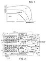
- FIG. 1 is a speed-load diagram showing various combustion domains in accordance with principles of the present invention.
- FIG. 2 is a general schematic diagram of portions of an exemplary diesel engine relevant to principles of the present invention.
- FIG. 3 is a flow diagram illustrating an embodiment of the inventive strategy.
- FIG. 1 is a graph whose vertical axis represents engine load and whose horizontal axis represents engine speed. At the origin of the graph, engine load is zero, and engine speed is zero.
- FIG. 1 shows diesel engine operation in distinct domains designated HCCI, HCCI+CD, and CD with respective solid lines demarcating the domains.
- the diesel engine operates by HCCI combustion in domain HCCI (domain 1 ), by HCCI+CD combustion in domain HCCI+CD (domain 2 ), and by CD combustion in domain CD (domain 3 ).
- HCCI combustion occurs in the domain having lowest engine speeds and smallest engine loads while CD combustion occurs in the domain having highest engine speeds and largest engine loads.
- HCCI+CD combustion occurs in a domain that is intermediate the other two.
- FIG. 2 shows a schematic of a diesel engine 10 that utilizes the inventive strategy for powering a motor vehicle.
- Engine 10 is a multi-cylinder engine that comprises cylinders 12 within which pistons reciprocate. Each piston is coupled to a respective throw of a crankshaft by a corresponding connecting rod.
- cylinders 12 are divided into multiple groups. In the example here of an eight-cylinder engine, there are two groups of four cylinders each. In a V-type diesel engine one group G 1 can be one bank of cylinders, whereas the other group G 2 can be the other cylinder bank. For an in-line I-6 diesel engine with six cylinders (not shown in the drawing), cylinders 1 , 3 , and 5 may form the first cylinder group, whereas cylinders 2 , 4 , and 6 may form the second cylinder group.
- Each group of cylinders has its intake manifold, its own exhaust manifold, its own EGR system, and its own turbocharger system.
- an intake manifold 14 serves cylinders 12 of group G 1
- an intake manifold 16 serves cylinders 12 of group G 2
- An exhaust manifold 18 serves cylinders 12 of group G 1
- an exhaust manifold 20 serves cylinders 12 of group G 2 .
- a turbocharger 22 is associated with manifolds 14 and 18
- a turbocharger 24 is associated with manifolds 16 and 20 .
- Each turbocharger is of the variable geometry type and comprises a respective compressor 22 C, 24 C and a respective turbine 22 T, 24 T.
- a respective charge air cooler 26 , 28 cools the charge air created by the respective compressor 22 C, 24 C before the charge air enters the respective intake manifold 14 , 16 .
- a respective EGR system 30 , 32 is associated with each cylinder group.
- EGR system 30 comprises an EGR cooler 30 C and an EGR valve 34 that allow exhaust gases from exhaust manifold 18 to be delivered for entrainment with charge air entering intake manifold 14 .
- EGR system 32 comprises an EGR cooler 32 C and an EGR valve 38 that allow exhaust gases from exhaust manifold 20 to be delivered for entrainment with charge air entering intake manifold 16 .
- Engine 10 has a fueling system that comprises fuel injectors for injecting diesel fuel into cylinders 12 .
- Engine also has a processor-based engine control unit (ECU) 40 that processes data from various sources to develop various control data for controlling various aspects of engine operation.
- the data processed by ECU 40 may originate at external sources, such as various sensors and/or be generated internally. Examples of data processed may include engine speed, intake manifold pressure, exhaust manifold pressure, fuel injection pressure, fueling quantity and timing, mass airflow, and accelerator pedal position.
- ECU 40 controls the injection of fuel into cylinders 12 by controlling the operation of the fueling system, including controlling the operation of the fuel injectors.
- the processing system embodied in ECU 40 can process data sufficiently fast to calculate, in real time, the timing and duration of device actuation to set both the timing and the amount of each injection of fuel into a cylinder. Such control capability is used to implement the inventive strategy.
- the group of fuel injectors that inject fuel into the cylinders of group G 1 are designated by the reference numeral 42 while the group of fuel injectors that inject fuel into the cylinders of group G 2 are designated by the reference numeral 44 .
- ECU 40 also controls both turbochargers 22 , 24 and both EGR valves 34 , 38 .
- ECU 40 comprises a processing system that includes stores for storing two maps for control of the two turbochargers.
- One map is a HCCI VGT map that is used for selecting turbocharger vane position to control intake manifold boost pressure and exhaust manifold back-pressure during HCCI combustion
- the other map is a CD map that is used to select turbocharger vane position to control intake manifold boost pressure and exhaust manifold back-pressure during CD combustion.
- the processing system of ECU 40 also comprises stores for storing two maps for control of the two EGR valves.
- One is a HCCI EGR valve map that selects the extent to which the EGR valve opens to control the EGR percentage during HCCI combustion
- the other is a CD EGR valve map that selects the extent to which EGR valve opens to control the EGR percentage during CD combustion.
- the processing system also comprises stores for storing two fuel injection maps for the fuel system.
- One is a HCCI fuel injection map that controls the fuel injection pressure, the fuel injection quantity, the fuel injection timing, the number of fuel injections, and the rate of injection, during HCCI combustion
- the other is a CD fuel injection map that controls the fuel injection pressure, the fuel injection quantity, the fuel injection timing, the number of fuel injections, and the rate of injection, during CD combustion.
- each of the maps referred to above may comprise multiple individual maps that collectively form what has been for convenience called a map.
- Various inputs to the various maps result in selection of proper data values from the maps for fuel, turbocharger, and EGR control.
- FIG. 3 shows a logic flow diagram 44 of the inventive strategy that is implemented in ECU 40 as an algorithm that is repeatedly executed by the processing system, enabling engine 10 to operate by hybrid combustion.
- the algorithm commences at a start 45 and then a decision point 46 for determining the combustion processes in the respective cylinder groups G 1 , G 2 .
- the decision point processes data relevant to engine operation, specifically engine speed and load with reference to FIG. 1 , to determine in which of the three domains HCCI, HCCI+CD, and CD, the engine is currently operating.
- ECU 40 fuels the cylinders of both groups G 1 , G 2 for HCCI combustion using an HCCI fueling map, operates turbochargers 22 , 24 consistent with HCCI combustion using an HCCI VGT map, and operates EGR valves 34 , 38 consistent with HCCI combustion using an HCCI EGR Valve map, as marked at 48 , 50 , 52 , 54 respectively in FIG. 3 .
- Each iteration of the algorithm ends at 55 .
- ECU 40 fuels the cylinders of both groups G 1 , G 2 for CD combustion using a CD fueling map, operates turbochargers 22 , 24 consistent with CD combustion using a CD VGT map, and operates EGR valves 34 , 38 consistent with HCCI combustion using a CD EGR Valve map, as marked at 56 , 58 , 60 , 62 respectively in FIG. 3 .
- decision point 46 determines that the engine is operating in the HCCI+CD domain, one of the two cylinder groups G 1 , G 2 fueled for HCCI combustion and the other group is fueled for CD combustion. For example, if cylinder group G 1 is fueled for HCCI combustion, cylinder group G 2 is fueled for CD combustion mode, and vice versa.
- ECU 40 When group G 1 is fueled for HCCI combustion with the engine operating in the HCCI+CD domain, ECU 40 operates fuel injector group 42 using the HCCI fueling map, operates turbocharger 22 using the HCCI VGT map, and operates EGR valve 34 using the HCCI EGR valve map, as marked by reference numerals 64 , 66 , 68 , 70 . With group G 2 being fueled for CD combustion, ECU 40 operates fuel injector group 44 using the CD fueling map, operates turbocharger 24 using the CD VGT map, and operates EGR valve 38 using the CD EGR valve map, as marked by reference numerals 72 , 74 , 76 , 78 . In each fueling mode, turbocharger operation and EGR valve operation are controlled by appropriate maps for the respective mode.
- An advantage of the present invention is significant reduction in both NOx and soot emissions from diesel engines.
- the engine operates by HCCI combustion, that is, both cylinder groups G 1 , G 2 work in the HCCI combustion mode, which produces very low NOx and soot emissions.
- the engine works in the HCCI+CD manner; that is, one cylinder group works in the HCCI combustion manner to generate very low emissions, whereas the other cylinder group works in the CD combustion manner.
- the resulting emissions can be reduced almost in half, in comparison with operation of both groups by CD combustion over the same range as that of the HCCI+CD domain.
- the cylinder group operating by HCCI combustion is fueled to provide the largest possible torque contribution to total torque consistent with HCCI combustion, while the cylinder group being fueled for CD combustion makes up the difference required.
- the fuel delivered into the HCCI cylinders is fixed, i.e., the fuel map is substantially constant, and does not change as load changes.
- the fuel delivered into HCCI cylinders changes from one fixed amount corresponding to maximum allowable fueling at the former speed to another fixed amount corresponding to the maximum allowable fueling at the new speed.
- HCCI fueling is a function of engine speed, but not engine load in the HCCI+CD mode.
- the HCCI domain covers an area that comprises various combinations of relatively smaller engine loads and relatively lower engine speeds.
- the HCCI+CD domain covers an area that comprises various combinations of relatively larger engine loads and relatively higher engine speeds than those of the HCCI domain.
- HCCI fueling may have one or more discrete injections. Regardless of the number of discrete injections, HCCI operation results from introducing fuel into a cylinder during a compression upstroke of the piston that reciprocates in the cylinder. The fuel mixes with charge air that entered the cylinder during the immediately preceding intake downstroke and early portion of the compression upstroke, and the resulting air-fuel mixture is a substantially homogeneous one. The HCCI fueling concludes before any combustion occurs. When the charge has been compressed sufficiently to auto-ignite, HCCI combustion commences.
- CD fueling may also have one or more discrete injections.
- Advantages of the invention include: concurrent reductions in both NO X and soot; ability to cover the entire operating range of an engine by virtue of the three domains that have been described; use in heavy-duty, medium-duty, and light-duty diesel engines.
Abstract
Description
Claims (6)
Priority Applications (1)
| Application Number | Priority Date | Filing Date | Title |
|---|---|---|---|
| US11/380,537 US7461627B2 (en) | 2006-04-27 | 2006-04-27 | Hybrid combustion in a diesel engine |
Applications Claiming Priority (1)
| Application Number | Priority Date | Filing Date | Title |
|---|---|---|---|
| US11/380,537 US7461627B2 (en) | 2006-04-27 | 2006-04-27 | Hybrid combustion in a diesel engine |
Publications (2)
| Publication Number | Publication Date |
|---|---|
| US20070251234A1 US20070251234A1 (en) | 2007-11-01 |
| US7461627B2 true US7461627B2 (en) | 2008-12-09 |
Family
ID=38647020
Family Applications (1)
| Application Number | Title | Priority Date | Filing Date |
|---|---|---|---|
| US11/380,537 Active 2026-06-28 US7461627B2 (en) | 2006-04-27 | 2006-04-27 | Hybrid combustion in a diesel engine |
Country Status (1)
| Country | Link |
|---|---|
| US (1) | US7461627B2 (en) |
Cited By (10)
| Publication number | Priority date | Publication date | Assignee | Title |
|---|---|---|---|---|
| US20100318276A1 (en) * | 2009-06-10 | 2010-12-16 | Zhengbai Liu | Control Strategy For A Diesel Engine During Lean-Rich Modulation |
| US20110079008A1 (en) * | 2006-10-02 | 2011-04-07 | De Ojeda William | Strategy For Control Of Recirculated Exhaust Gas To Null Turbocharger Boost Error |
| US20110180049A1 (en) * | 2008-07-18 | 2011-07-28 | Elsaesser Alfred | Fresh air system |
| US8010276B2 (en) | 2009-08-31 | 2011-08-30 | International Engine Intellectual Property Company, Llc | Intake manifold oxygen control |
| US20120023934A1 (en) * | 2010-09-09 | 2012-02-02 | Ford Global Technologies, Llc | Method and system for a turbocharged engine |
| US20120046854A1 (en) * | 2010-08-20 | 2012-02-23 | Mazda Motor Corporation | Method and device for controlling diesel engine |
| US20120255299A1 (en) * | 2009-11-06 | 2012-10-11 | Rolf Gunkel | V engine |
| US8306710B2 (en) | 2010-04-14 | 2012-11-06 | International Engine Intellectual Property Company, Llc | Method for diesel particulate filter regeneration in a vehicle equipped with a hybrid engine background of the invention |
| US20160138491A1 (en) * | 2014-11-13 | 2016-05-19 | Dr. Ing. H.C. F. Porsche Aktiengesellschaft | Method and control device for operating an internal combustion engine |
| US11927157B1 (en) | 2023-02-06 | 2024-03-12 | International Engine Intellectual Property Company, Llc | Heat exchanger cleaning system and method |
Families Citing this family (3)
| Publication number | Priority date | Publication date | Assignee | Title |
|---|---|---|---|---|
| DE102009030771A1 (en) * | 2009-06-27 | 2010-12-30 | Mahle International Gmbh | Piston engine and operating procedures |
| US10982589B1 (en) * | 2019-11-19 | 2021-04-20 | Transportation Ip Holdings, Llc | Methods and systems for a charge air cooler |
| US11156191B2 (en) * | 2019-11-22 | 2021-10-26 | Southwest Research Institute | Internal combustion engine with cross-boosting turbochargers |
Citations (19)
| Publication number | Priority date | Publication date | Assignee | Title |
|---|---|---|---|---|
| US5785031A (en) | 1996-07-15 | 1998-07-28 | Fuji Jukogyo Kabushiki Kaisha | Combustion control system for in-cylinder fuel injection engine and the method thereof |
| US5832880A (en) | 1997-07-28 | 1998-11-10 | Southwest Research Institute | Apparatus and method for controlling homogeneous charge compression ignition combustion in diesel engines |
| US5875743A (en) | 1997-07-28 | 1999-03-02 | Southwest Research Institute | Apparatus and method for reducing emissions in a dual combustion mode diesel engine |
| US5881693A (en) | 1996-12-18 | 1999-03-16 | Toyota Jidosha Kabushiki Kaisha | Apparatus and method for controlling combustion in internal combustion engines |
| US5896840A (en) | 1996-12-19 | 1999-04-27 | Toyota Jidosha Kabushiki Kaisha | Combustion controller for internal combustion engines |
| US5937822A (en) | 1997-06-03 | 1999-08-17 | Nissan Motor Co., Ltd. | Control system for internal combustion engine |
| US6390054B1 (en) * | 2000-08-26 | 2002-05-21 | Ford Global Technologies, Inc. | Engine control strategy for a hybrid HCCI engine |
| US20030145836A1 (en) | 2001-08-17 | 2003-08-07 | Jan-Roger Linna | Method of controlling combustion in a homogeneous charge compression ignition engine |
| US6662785B1 (en) | 2003-01-06 | 2003-12-16 | General Motors Corporation | Method of operating HCCI engines at low speed and low load |
| US6684849B2 (en) | 2000-05-08 | 2004-02-03 | Cummins Inc. | Multiple operating mode engine and method of operation |
| US6725838B2 (en) | 2001-10-09 | 2004-04-27 | Caterpillar Inc | Fuel injector having dual mode capabilities and engine using same |
| US20040182359A1 (en) | 2003-03-17 | 2004-09-23 | Stewart Daniel W. | Individual cylinder-switching in a multi-cylinder engine |
| US6840209B2 (en) | 2001-09-07 | 2005-01-11 | Isuzu Motors Limited | Direct injection diesel engine |
| US6957640B1 (en) * | 2004-06-23 | 2005-10-25 | International Engine Intellectual Property Company, Llc | Strategy for fueling a diesel engine by selective use of fueling maps to provide HCCI+RVT, HCCI+VVT, and CD+RVT combustion modes |
| US7017561B1 (en) * | 2005-03-03 | 2006-03-28 | International Engine Intellectual Property Company, Llc | Control strategy for expanding diesel HCCI combustion range by lowering intake manifold temperature |
| US7021276B2 (en) * | 2004-03-25 | 2006-04-04 | International Engine Intellectual Property Company, Llc | Control strategy for HCCI-CD combustion in a diesel engine using two fuel injection phases |
| US7255095B1 (en) * | 2006-02-17 | 2007-08-14 | Ford Global Technologies, Llc | Dual combustion mode engine |
| US20080027618A1 (en) * | 2004-06-23 | 2008-01-31 | Zhengbal Liu | Strategy for Fueling a Diesel Engine by Selective Use of Fueling Maps to Provide Hcci, Hcci+Cd, and Cd Combustion Modes |
| US7343902B2 (en) * | 2006-02-17 | 2008-03-18 | Ford Global Technologies Llc | Dual combustion mode engine |
-
2006
- 2006-04-27 US US11/380,537 patent/US7461627B2/en active Active
Patent Citations (20)
| Publication number | Priority date | Publication date | Assignee | Title |
|---|---|---|---|---|
| US5785031A (en) | 1996-07-15 | 1998-07-28 | Fuji Jukogyo Kabushiki Kaisha | Combustion control system for in-cylinder fuel injection engine and the method thereof |
| US5881693A (en) | 1996-12-18 | 1999-03-16 | Toyota Jidosha Kabushiki Kaisha | Apparatus and method for controlling combustion in internal combustion engines |
| US5896840A (en) | 1996-12-19 | 1999-04-27 | Toyota Jidosha Kabushiki Kaisha | Combustion controller for internal combustion engines |
| US5937822A (en) | 1997-06-03 | 1999-08-17 | Nissan Motor Co., Ltd. | Control system for internal combustion engine |
| US5832880A (en) | 1997-07-28 | 1998-11-10 | Southwest Research Institute | Apparatus and method for controlling homogeneous charge compression ignition combustion in diesel engines |
| US5875743A (en) | 1997-07-28 | 1999-03-02 | Southwest Research Institute | Apparatus and method for reducing emissions in a dual combustion mode diesel engine |
| US6684849B2 (en) | 2000-05-08 | 2004-02-03 | Cummins Inc. | Multiple operating mode engine and method of operation |
| US6390054B1 (en) * | 2000-08-26 | 2002-05-21 | Ford Global Technologies, Inc. | Engine control strategy for a hybrid HCCI engine |
| US20030145836A1 (en) | 2001-08-17 | 2003-08-07 | Jan-Roger Linna | Method of controlling combustion in a homogeneous charge compression ignition engine |
| US6840209B2 (en) | 2001-09-07 | 2005-01-11 | Isuzu Motors Limited | Direct injection diesel engine |
| US6725838B2 (en) | 2001-10-09 | 2004-04-27 | Caterpillar Inc | Fuel injector having dual mode capabilities and engine using same |
| US6662785B1 (en) | 2003-01-06 | 2003-12-16 | General Motors Corporation | Method of operating HCCI engines at low speed and low load |
| US20040182359A1 (en) | 2003-03-17 | 2004-09-23 | Stewart Daniel W. | Individual cylinder-switching in a multi-cylinder engine |
| US7021276B2 (en) * | 2004-03-25 | 2006-04-04 | International Engine Intellectual Property Company, Llc | Control strategy for HCCI-CD combustion in a diesel engine using two fuel injection phases |
| US6957640B1 (en) * | 2004-06-23 | 2005-10-25 | International Engine Intellectual Property Company, Llc | Strategy for fueling a diesel engine by selective use of fueling maps to provide HCCI+RVT, HCCI+VVT, and CD+RVT combustion modes |
| US7121255B2 (en) * | 2004-06-23 | 2006-10-17 | International Engine Intellectual Property Company, Llc | Strategy for fueling a diesel engine by selective use of fueling maps to provide HCCI+RVT, HCCI+IVC, HCCI+IVC+EVC, and CD+RVT combustion modes |
| US20080027618A1 (en) * | 2004-06-23 | 2008-01-31 | Zhengbal Liu | Strategy for Fueling a Diesel Engine by Selective Use of Fueling Maps to Provide Hcci, Hcci+Cd, and Cd Combustion Modes |
| US7017561B1 (en) * | 2005-03-03 | 2006-03-28 | International Engine Intellectual Property Company, Llc | Control strategy for expanding diesel HCCI combustion range by lowering intake manifold temperature |
| US7255095B1 (en) * | 2006-02-17 | 2007-08-14 | Ford Global Technologies, Llc | Dual combustion mode engine |
| US7343902B2 (en) * | 2006-02-17 | 2008-03-18 | Ford Global Technologies Llc | Dual combustion mode engine |
Non-Patent Citations (1)
| Title |
|---|
| Vafidis, C., "The Application of an Electro-hydraulic VVA System on a Passenger Car C.R. Diesel Engine," ATA (Associacioni Tecnica De Automobile) Congress, Porto Cervo, Italy, Oct. 12-13, 2000, Paper No. 20A2011. |
Cited By (15)
| Publication number | Priority date | Publication date | Assignee | Title |
|---|---|---|---|---|
| US20110079008A1 (en) * | 2006-10-02 | 2011-04-07 | De Ojeda William | Strategy For Control Of Recirculated Exhaust Gas To Null Turbocharger Boost Error |
| US20110180049A1 (en) * | 2008-07-18 | 2011-07-28 | Elsaesser Alfred | Fresh air system |
| US8991366B2 (en) * | 2008-07-18 | 2015-03-31 | Mahle International Gmbh | Fresh air system |
| US20100318276A1 (en) * | 2009-06-10 | 2010-12-16 | Zhengbai Liu | Control Strategy For A Diesel Engine During Lean-Rich Modulation |
| US8010276B2 (en) | 2009-08-31 | 2011-08-30 | International Engine Intellectual Property Company, Llc | Intake manifold oxygen control |
| US20120255299A1 (en) * | 2009-11-06 | 2012-10-11 | Rolf Gunkel | V engine |
| US9175602B2 (en) * | 2009-11-06 | 2015-11-03 | Mtu Friedrichshafen Gmbh | V engine |
| US8306710B2 (en) | 2010-04-14 | 2012-11-06 | International Engine Intellectual Property Company, Llc | Method for diesel particulate filter regeneration in a vehicle equipped with a hybrid engine background of the invention |
| US20120046854A1 (en) * | 2010-08-20 | 2012-02-23 | Mazda Motor Corporation | Method and device for controlling diesel engine |
| US8770174B2 (en) * | 2010-08-20 | 2014-07-08 | Mazda Motor Corporation | Method and device for controlling diesel engine |
| US8701409B2 (en) * | 2010-09-09 | 2014-04-22 | Ford Global Technologies, Llc | Method and system for a turbocharged engine |
| US20120023934A1 (en) * | 2010-09-09 | 2012-02-02 | Ford Global Technologies, Llc | Method and system for a turbocharged engine |
| US20160138491A1 (en) * | 2014-11-13 | 2016-05-19 | Dr. Ing. H.C. F. Porsche Aktiengesellschaft | Method and control device for operating an internal combustion engine |
| US9915193B2 (en) * | 2014-11-13 | 2018-03-13 | Dr. Ing. H.C.F. Porsche Aktiengesellschaft | Method and control device for operating an internal combustion engine |
| US11927157B1 (en) | 2023-02-06 | 2024-03-12 | International Engine Intellectual Property Company, Llc | Heat exchanger cleaning system and method |
Also Published As
| Publication number | Publication date |
|---|---|
| US20070251234A1 (en) | 2007-11-01 |
Similar Documents
| Publication | Publication Date | Title |
|---|---|---|
| US7461627B2 (en) | Hybrid combustion in a diesel engine | |
| US10450973B2 (en) | Techniques for controlling a dedicated EGR engine | |
| US7017561B1 (en) | Control strategy for expanding diesel HCCI combustion range by lowering intake manifold temperature | |
| US7021276B2 (en) | Control strategy for HCCI-CD combustion in a diesel engine using two fuel injection phases | |
| JP4859832B2 (en) | Fuel supply to diesel engine in HCCI combustion mode, HCCI + CD combustion mode and CD combustion mode by selectively using fuel supply map | |
| US7117843B2 (en) | Emission reduction in a diesel engine using an alternative combustion process and a low-pressure EGR loop | |
| US7631489B2 (en) | Strategy for selectively bypassing a DPF in a hybrid HCCI combustion engine | |
| US6957640B1 (en) | Strategy for fueling a diesel engine by selective use of fueling maps to provide HCCI+RVT, HCCI+VVT, and CD+RVT combustion modes | |
| US7426922B2 (en) | Engine exhaust gas purifier | |
| US8315777B2 (en) | Control apparatus and control method for internal combustion engine | |
| US7703442B2 (en) | Method for operating an internal combustion engine | |
| US20150068490A1 (en) | Multi-fuel engine with variable valve timing | |
| US20100076668A1 (en) | Control apparatus for internal combustion engine | |
| JP5086071B2 (en) | Fueling a diesel engine by selectively using a fueling map to extend the range of HCCI combustion | |
| US20140373530A1 (en) | Multi-fuel engine |
Legal Events
| Date | Code | Title | Description |
|---|---|---|---|
| AS | Assignment |
Owner name: INTERNATIONAL ENGINE INTELLECTUAL PROPERTY COMPANY Free format text: ASSIGNMENT OF ASSIGNORS INTEREST;ASSIGNORS:LIU, ZHENGBAI;WEI, PUNING;REEL/FRAME:017540/0154 Effective date: 20060410 |
|
| STCF | Information on status: patent grant |
Free format text: PATENTED CASE |
|
| FPAY | Fee payment |
Year of fee payment: 4 |
|
| AS | Assignment |
Owner name: JPMORGAN CHASE BANK, N.A., AS COLLATERAL AGENT, NE Free format text: SECURITY AGREEMENT;ASSIGNORS:INTERNATIONAL ENGINE INTELLECTUAL PROPERTY COMPANY, LLC;INTERNATIONAL TRUCK INTELLECTUAL PROPERTY COMPANY, LLC;NAVISTAR INTERNATIONAL CORPORATION;AND OTHERS;REEL/FRAME:028944/0730 Effective date: 20120817 |
|
| AS | Assignment |
Owner name: JPMORGAN CHASE BANK N.A., AS COLLATERAL AGENT, NEW Free format text: SECURITY AGREEMENT;ASSIGNORS:NAVISTAR INTERNATIONAL CORPORATION;INTERNATIONAL TRUCK INTELLECTUAL PROPERTY COMPANY, LLC;INTERNATIONAL ENGINE INTELLECTUAL PROPERTY COMPANY, LLC;REEL/FRAME:036616/0243 Effective date: 20150807 |
|
| FPAY | Fee payment |
Year of fee payment: 8 |
|
| AS | Assignment |
Owner name: JPMORGAN CHASE BANK, N.A., AS COLLATERAL AGENT, NEW YORK Free format text: SECURITY INTEREST;ASSIGNORS:NAVISTAR INTERNATIONAL CORPORATION;NAVISTAR, INC.;REEL/FRAME:044418/0310 Effective date: 20171106 Owner name: INTERNATIONAL TRUCK INTELLECTUAL PROPERTY COMPANY, Free format text: RELEASE BY SECURED PARTY;ASSIGNOR:JPMORGAN CHASE BANK, N.A., AS COLLATERAL AGENT;REEL/FRAME:044780/0456 Effective date: 20171106 Owner name: NAVISTAR INTERNATIONAL CORPORATION, ILLINOIS Free format text: RELEASE BY SECURED PARTY;ASSIGNOR:JPMORGAN CHASE BANK, N.A., AS COLLATERAL AGENT;REEL/FRAME:044780/0456 Effective date: 20171106 Owner name: INTERNATIONAL ENGINE INTELLECTUAL PROPERTY COMPANY Free format text: RELEASE BY SECURED PARTY;ASSIGNOR:JPMORGAN CHASE BANK, N.A., AS COLLATERAL AGENT;REEL/FRAME:044780/0456 Effective date: 20171106 Owner name: JPMORGAN CHASE BANK, N.A., AS COLLATERAL AGENT, NE Free format text: SECURITY INTEREST;ASSIGNORS:NAVISTAR INTERNATIONAL CORPORATION;NAVISTAR, INC.;REEL/FRAME:044418/0310 Effective date: 20171106 Owner name: INTERNATIONAL TRUCK INTELLECTUAL PROPERTY COMPANY, Free format text: RELEASE BY SECURED PARTY;ASSIGNOR:JPMORGAN CHASE BANK, N.A., AS COLLATERAL AGENT;REEL/FRAME:044416/0867 Effective date: 20171106 Owner name: INTERNATIONAL ENGINE INTELLECTUAL PROPERTY COMPANY Free format text: RELEASE BY SECURED PARTY;ASSIGNOR:JPMORGAN CHASE BANK, N.A., AS COLLATERAL AGENT;REEL/FRAME:044416/0867 Effective date: 20171106 Owner name: NAVISTAR, INC., ILLINOIS Free format text: RELEASE BY SECURED PARTY;ASSIGNOR:JPMORGAN CHASE BANK, N.A., AS COLLATERAL AGENT;REEL/FRAME:044416/0867 Effective date: 20171106 Owner name: NAVISTAR INTERNATIONAL CORPORATION, ILLINOIS Free format text: RELEASE BY SECURED PARTY;ASSIGNOR:JPMORGAN CHASE BANK, N.A., AS COLLATERAL AGENT;REEL/FRAME:044416/0867 Effective date: 20171106 |
|
| AS | Assignment |
Owner name: JPMORGAN CHASE BANK, N.A., AS ADMINISTRATIVE AGENT, NEW YORK Free format text: SECURITY INTEREST;ASSIGNORS:INTERNATIONAL TRUCK INTELLECTUAL PROPERTY COMPANY, LLC;INTERNATIONAL ENGINE INTELLECTUAL PROPERTY COMPANY, LLC;NAVISTAR, INC. (F/K/A INTERNATIONAL TRUCK AND ENGINE CORPORATION);REEL/FRAME:052483/0742 Effective date: 20200423 |
|
| AS | Assignment |
Owner name: THE BANK OF NEW YORK MELLON TRUST COMPANY, N.A., AS COLLATERAL AGENT, ILLINOIS Free format text: SECURITY INTEREST;ASSIGNORS:NAVISTAR INTERNATIONAL CORPORATION;INTERNATIONAL ENGINE INTELLECTUAL PROPERTY COMPANY, LLC;INTERNATIONAL TRUCK INTELLECTUAL PROPERTY COMPANY, LLC;AND OTHERS;REEL/FRAME:053545/0443 Effective date: 20200427 Owner name: JPMORGAN CHASE BANK, N.A., AS ADMINISTRATIVE AGENT, NEW YORK Free format text: CORRECTIVE ASSIGNMENT TO CORRECT THE CONVEYING PARTY DATA PREVIOUSLY RECORDED AT REEL: 052483 FRAME: 0742. ASSIGNOR(S) HEREBY CONFIRMS THE SECURITY INTEREST.;ASSIGNORS:NAVISTAR INTERNATIONAL CORPORATION;INTERNATIONAL ENGINE INTELLECTUAL PROPERTY COMPANY, LLC;INTERNATIONAL TRUCK INTELLECTUAL PROPERTY COMPANY, LLC;AND OTHERS;REEL/FRAME:053457/0001 Effective date: 20200423 |
|
| MAFP | Maintenance fee payment |
Free format text: PAYMENT OF MAINTENANCE FEE, 12TH YEAR, LARGE ENTITY (ORIGINAL EVENT CODE: M1553); ENTITY STATUS OF PATENT OWNER: LARGE ENTITY Year of fee payment: 12 |
|
| AS | Assignment |
Owner name: INTERNATIONAL TRUCK INTELLECTUAL PROPERTY COMPANY, LLC, ILLINOIS Free format text: RELEASE BY SECURED PARTY;ASSIGNOR:JPMORGAN CHASE BANK, N.A., AS ADMINISTRATIVE AGENT;REEL/FRAME:056757/0136 Effective date: 20210701 Owner name: NAVISTAR, INC. (F/KA/ INTERNATIONAL TRUCK AND ENGINE CORPORATION), ILLINOIS Free format text: RELEASE BY SECURED PARTY;ASSIGNOR:JPMORGAN CHASE BANK, N.A., AS ADMINISTRATIVE AGENT;REEL/FRAME:056757/0136 Effective date: 20210701 Owner name: INTERNATIONAL ENGINE INTELLECTUAL PROPERTY COMPANY, LLC, ILLINOIS Free format text: RELEASE BY SECURED PARTY;ASSIGNOR:JPMORGAN CHASE BANK, N.A., AS ADMINISTRATIVE AGENT;REEL/FRAME:056757/0136 Effective date: 20210701 |
|
| AS | Assignment |
Owner name: NAVISTAR, INC., ILLINOIS Free format text: RELEASE OF SECURITY INTEREST RECORDED AT REEL/FRAME 53545/443;ASSIGNOR:THE BANK OF NEW YORK MELLON TRUST COMPANY, N.A.;REEL/FRAME:057441/0404 Effective date: 20210701 Owner name: INTERNATIONAL ENGINE INTELLECTUAL PROPERTY COMPANY, LLC, ILLINOIS Free format text: RELEASE OF SECURITY INTEREST RECORDED AT REEL/FRAME 53545/443;ASSIGNOR:THE BANK OF NEW YORK MELLON TRUST COMPANY, N.A.;REEL/FRAME:057441/0404 Effective date: 20210701 Owner name: INTERNATIONAL TRUCK INTELLECTUAL PROPERTY COMPANY, LLC, ILLINOIS Free format text: RELEASE OF SECURITY INTEREST RECORDED AT REEL/FRAME 53545/443;ASSIGNOR:THE BANK OF NEW YORK MELLON TRUST COMPANY, N.A.;REEL/FRAME:057441/0404 Effective date: 20210701 Owner name: NAVISTAR INTERNATIONAL CORPORATION, ILLINOIS Free format text: RELEASE OF SECURITY INTEREST RECORDED AT REEL/FRAME 53545/443;ASSIGNOR:THE BANK OF NEW YORK MELLON TRUST COMPANY, N.A.;REEL/FRAME:057441/0404 Effective date: 20210701 |