US7439655B2 - Laminated-type piezoelectric element - Google Patents
Laminated-type piezoelectric element Download PDFInfo
- Publication number
- US7439655B2 US7439655B2 US11/405,493 US40549306A US7439655B2 US 7439655 B2 US7439655 B2 US 7439655B2 US 40549306 A US40549306 A US 40549306A US 7439655 B2 US7439655 B2 US 7439655B2
- Authority
- US
- United States
- Prior art keywords
- laminated
- piezoelectric element
- type piezoelectric
- external electrode
- electrode layer
- Prior art date
- Legal status (The legal status is an assumption and is not a legal conclusion. Google has not performed a legal analysis and makes no representation as to the accuracy of the status listed.)
- Expired - Fee Related, expires
Links
- 239000000853 adhesive Substances 0.000 claims abstract description 118
- 230000001070 adhesive effect Effects 0.000 claims abstract description 118
- 239000000446 fuel Substances 0.000 claims description 19
- PXHVJJICTQNCMI-UHFFFAOYSA-N Nickel Chemical compound [Ni] PXHVJJICTQNCMI-UHFFFAOYSA-N 0.000 claims description 15
- KDLHZDBZIXYQEI-UHFFFAOYSA-N Palladium Chemical compound [Pd] KDLHZDBZIXYQEI-UHFFFAOYSA-N 0.000 claims description 11
- BQCADISMDOOEFD-UHFFFAOYSA-N Silver Chemical compound [Ag] BQCADISMDOOEFD-UHFFFAOYSA-N 0.000 claims description 10
- 238000002347 injection Methods 0.000 claims description 10
- 239000007924 injection Substances 0.000 claims description 10
- 229910052751 metal Inorganic materials 0.000 claims description 10
- 239000002184 metal Substances 0.000 claims description 10
- 229920005989 resin Polymers 0.000 claims description 10
- 239000011347 resin Substances 0.000 claims description 10
- 229910052709 silver Inorganic materials 0.000 claims description 10
- 239000004332 silver Substances 0.000 claims description 10
- XEEYBQQBJWHFJM-UHFFFAOYSA-N Iron Chemical compound [Fe] XEEYBQQBJWHFJM-UHFFFAOYSA-N 0.000 claims description 8
- 229910052802 copper Inorganic materials 0.000 claims description 8
- 239000010949 copper Substances 0.000 claims description 8
- 229910052759 nickel Inorganic materials 0.000 claims description 8
- RYGMFSIKBFXOCR-UHFFFAOYSA-N Copper Chemical compound [Cu] RYGMFSIKBFXOCR-UHFFFAOYSA-N 0.000 claims description 7
- BASFCYQUMIYNBI-UHFFFAOYSA-N platinum Chemical compound [Pt] BASFCYQUMIYNBI-UHFFFAOYSA-N 0.000 claims description 7
- 229910045601 alloy Inorganic materials 0.000 claims description 6
- 239000000956 alloy Substances 0.000 claims description 6
- 239000007937 lozenge Substances 0.000 claims description 5
- 229910052763 palladium Inorganic materials 0.000 claims description 5
- 239000000919 ceramic Substances 0.000 claims description 4
- 229910052737 gold Inorganic materials 0.000 claims description 4
- 239000010931 gold Substances 0.000 claims description 4
- 229910052742 iron Inorganic materials 0.000 claims description 4
- 229910052697 platinum Inorganic materials 0.000 claims description 4
- 229910001220 stainless steel Inorganic materials 0.000 claims description 4
- 239000004962 Polyamide-imide Substances 0.000 claims description 3
- 239000003822 epoxy resin Substances 0.000 claims description 3
- PCHJSUWPFVWCPO-UHFFFAOYSA-N gold Chemical compound [Au] PCHJSUWPFVWCPO-UHFFFAOYSA-N 0.000 claims description 3
- 229920002312 polyamide-imide Polymers 0.000 claims description 3
- 229920000647 polyepoxide Polymers 0.000 claims description 3
- 229920001225 polyester resin Polymers 0.000 claims description 3
- 239000004645 polyester resin Substances 0.000 claims description 3
- 229920001721 polyimide Polymers 0.000 claims description 3
- 239000009719 polyimide resin Substances 0.000 claims description 3
- 229920002050 silicone resin Polymers 0.000 claims description 3
- 239000010935 stainless steel Substances 0.000 claims description 3
- 229920002803 thermoplastic polyurethane Polymers 0.000 claims description 3
- 238000006073 displacement reaction Methods 0.000 description 21
- 238000000034 method Methods 0.000 description 9
- 239000004020 conductor Substances 0.000 description 7
- 230000035882 stress Effects 0.000 description 6
- 238000004891 communication Methods 0.000 description 5
- 230000000694 effects Effects 0.000 description 4
- 239000000203 mixture Substances 0.000 description 4
- 239000002002 slurry Substances 0.000 description 4
- 238000005219 brazing Methods 0.000 description 3
- 239000012141 concentrate Substances 0.000 description 3
- 239000000463 material Substances 0.000 description 3
- 230000000149 penetrating effect Effects 0.000 description 3
- 238000003825 pressing Methods 0.000 description 3
- 238000005476 soldering Methods 0.000 description 3
- 230000008602 contraction Effects 0.000 description 2
- 230000007423 decrease Effects 0.000 description 2
- 230000003247 decreasing effect Effects 0.000 description 2
- 230000005684 electric field Effects 0.000 description 2
- 238000010292 electrical insulation Methods 0.000 description 2
- 229910000464 lead oxide Inorganic materials 0.000 description 2
- 238000004519 manufacturing process Methods 0.000 description 2
- YEXPOXQUZXUXJW-UHFFFAOYSA-N oxolead Chemical compound [Pb]=O YEXPOXQUZXUXJW-UHFFFAOYSA-N 0.000 description 2
- 239000000843 powder Substances 0.000 description 2
- IATRAKWUXMZMIY-UHFFFAOYSA-N strontium oxide Chemical compound [O-2].[Sr+2] IATRAKWUXMZMIY-UHFFFAOYSA-N 0.000 description 2
- 230000008646 thermal stress Effects 0.000 description 2
- XLYOFNOQVPJJNP-UHFFFAOYSA-N water Substances O XLYOFNOQVPJJNP-UHFFFAOYSA-N 0.000 description 2
- GWEVSGVZZGPLCZ-UHFFFAOYSA-N Titan oxide Chemical compound O=[Ti]=O GWEVSGVZZGPLCZ-UHFFFAOYSA-N 0.000 description 1
- 230000015556 catabolic process Effects 0.000 description 1
- 229910010293 ceramic material Inorganic materials 0.000 description 1
- 238000005520 cutting process Methods 0.000 description 1
- 239000002270 dispersing agent Substances 0.000 description 1
- 238000005530 etching Methods 0.000 description 1
- 239000002828 fuel tank Substances 0.000 description 1
- 239000011521 glass Substances 0.000 description 1
- 229910000484 niobium oxide Inorganic materials 0.000 description 1
- URLJKFSTXLNXLG-UHFFFAOYSA-N niobium(5+);oxygen(2-) Chemical compound [O-2].[O-2].[O-2].[O-2].[O-2].[Nb+5].[Nb+5] URLJKFSTXLNXLG-UHFFFAOYSA-N 0.000 description 1
- 230000003287 optical effect Effects 0.000 description 1
- RVTZCBVAJQQJTK-UHFFFAOYSA-N oxygen(2-);zirconium(4+) Chemical compound [O-2].[O-2].[Zr+4] RVTZCBVAJQQJTK-UHFFFAOYSA-N 0.000 description 1
- 238000007747 plating Methods 0.000 description 1
- 238000004080 punching Methods 0.000 description 1
- 238000007650 screen-printing Methods 0.000 description 1
- OGIDPMRJRNCKJF-UHFFFAOYSA-N titanium oxide Inorganic materials [Ti]=O OGIDPMRJRNCKJF-UHFFFAOYSA-N 0.000 description 1
- 238000007740 vapor deposition Methods 0.000 description 1
- 238000009834 vaporization Methods 0.000 description 1
- 230000008016 vaporization Effects 0.000 description 1
- 229910001928 zirconium oxide Inorganic materials 0.000 description 1
Images


Classifications
-
- H—ELECTRICITY
- H10—SEMICONDUCTOR DEVICES; ELECTRIC SOLID-STATE DEVICES NOT OTHERWISE PROVIDED FOR
- H10N—ELECTRIC SOLID-STATE DEVICES NOT OTHERWISE PROVIDED FOR
- H10N30/00—Piezoelectric or electrostrictive devices
- H10N30/80—Constructional details
- H10N30/87—Electrodes or interconnections, e.g. leads or terminals
- H10N30/872—Interconnections, e.g. connection electrodes of multilayer piezoelectric or electrostrictive devices
-
- F—MECHANICAL ENGINEERING; LIGHTING; HEATING; WEAPONS; BLASTING
- F02—COMBUSTION ENGINES; HOT-GAS OR COMBUSTION-PRODUCT ENGINE PLANTS
- F02M—SUPPLYING COMBUSTION ENGINES IN GENERAL WITH COMBUSTIBLE MIXTURES OR CONSTITUENTS THEREOF
- F02M51/00—Fuel-injection apparatus characterised by being operated electrically
- F02M51/005—Arrangement of electrical wires and connections, e.g. wire harness, sockets, plugs; Arrangement of electronic control circuits in or on fuel injection apparatus
-
- F—MECHANICAL ENGINEERING; LIGHTING; HEATING; WEAPONS; BLASTING
- F02—COMBUSTION ENGINES; HOT-GAS OR COMBUSTION-PRODUCT ENGINE PLANTS
- F02M—SUPPLYING COMBUSTION ENGINES IN GENERAL WITH COMBUSTIBLE MIXTURES OR CONSTITUENTS THEREOF
- F02M51/00—Fuel-injection apparatus characterised by being operated electrically
- F02M51/06—Injectors peculiar thereto with means directly operating the valve needle
- F02M51/0603—Injectors peculiar thereto with means directly operating the valve needle using piezoelectric or magnetostrictive operating means
Definitions
- the present invention relates to a laminated-type piezoelectric element utilized in, for example, an injection valve for injecting fuel in an automobile, a finely-positioning device of an optical device and the like, a driving element for preventing vibration, and an ink-jet printer.
- a laminated-type piezoelectric element utilized in such a piezoelectric actuator when it has been continuously driven under a strong electric field and a high pressure for a long period, external electrodes for a positive electrode and a negative electrode disposed at side areas of the laminated-type piezoelectric element cannot follow movements of expansion and contraction of the laminated-type piezoelectric element. Therefore, peeling occurs between the internal electrode formed between piezoelectric bodies and the external electrode, or a crack occurs at the external electrode and the external electrode breaks. Thereby, a problem occurs where an electric voltage is not supplied to a part of the piezoelectric body, and the displacement properties change during driving.
- Japanese unexamined patent publication No. 8-242025 proposes a laminated-type piezoelectric element wherein a thin sheet of an electrically conductive material, where a notch was formed in a width direction, is connected to a side area of the laminated-type piezoelectric element with an electrically conductive adhesive so as to make the thin sheet of an electrically conductive material electrically continuous with an internal electrode.
- a purpose of the present invention is to provide a laminated-type piezoelectric element which offers an effect that the connecting strength between the internal electrode formed in the piezoelectric body and the external electrode is high even if an electrically conductive adhesive is utilized, and displacement properties do not easily change during driving even if a part of the external electrode breaks.
- the present invention provides a laminated-type piezoelectric element, comprising piezoelectric layers composed of a ceramic being expansible and contractible by an applied electric voltage, internal electrode layers which are stacked alternately with the piezoelectric layers to form the laminated-type piezoelectric element and to supply the electric voltage to the piezoelectric layers, and first external electrode layers which are disposed on side areas of the laminated-type piezoelectric element, are electrically continuous to the internal electrode layers, and comprise plural opening portions being expansible and contractible in a stacking direction of the laminated-type piezoelectric element, wherein the first external electrode layer is connected to the laminated-type piezoelectric element via an electrically conductive adhesive member, and a width of the electrically conductive adhesive member is narrower than a width of the first external electrode layer.
- the first external electrode layer strongly connects to the laminated-type piezoelectric element, as the electrically conductive adhesive member penetrates into the opening portion of the first external electrode layer to form a connection in the shape of an anchor.
- the electrical conductivity for the internal electrode layers can be secured by a part of the first external electrode layer which is not fixed to the electrically conductive adhesive member, even when a part of the first external electrode layer fixed to the electrically conductive adhesive member is broken by a displacement of the piezoelectric layers and the like.
- the laminated-type piezoelectric element can be provided, where the connecting strength between the internal electrode layers formed at the laminated-type piezoelectric element and the first external electrode layer is high, and the displacement properties do not easily change even if a part of the first external electrode layer was broken.
- the laminated-type piezoelectric element is provided, where the width of the electrically conductive adhesive member is not less than 0.3 mm.
- the connecting strength is sufficiently high for the laminated-type piezoelectric element, even if the adhesive with the adhering strength of not greater than 20 MPa.
- the laminated-type piezoelectric element is provided, where a maximum width of the opening portion in a perpendicular direction to the stacking direction of the laminated-type piezoelectric element is not greater than 0.5 Wm, wherein Wm represents the width of the first external electrode layer.
- the laminated-type piezoelectric element is provided, where a shape of the opening portion is a circle or an ellipse.
- the first external electrode layer seldom breaks because the opening portion has a shape with no angle where a stress due to the displacement of the piezoelectric layers and the like does not easily concentrate.
- the laminated-type piezoelectric element is provided, where a shape of the opening portion is a polygon rounded at corners.
- the first external electrode layer seldom breaks because the opening portion has a rounded shape where a stress due to the displacement of the piezoelectric layers and the like does not easily concentrate.
- the laminated-type piezoelectric element is provided, where a shape of the opening portion is a quadrangle or a lozenge, further especially where a width Ws of the electrically conductive adhesive member is represented by the following formula, Ws ⁇ Wm ⁇ h wherein Wm represents a width of the first external electrode layer, and h represents a height of a triangle with three sides of “a”, “b” and “L 2 ”, wherein “a” and “b” represent respectively lengths of two sides adjoining to each other in the stacking direction at the opening portion formed in the shape of a quadrangle or a lozenge, and “L 2 ” represents a width of the opening portion in the stacking direction of the laminated-type piezoelectric element.
- the electrical conductivity for the internal electrode layers can be secured by a part of the first external electrode layer which is not fixed to the electrically conductive adhesive member, even when a part of the first external electrode layer fixed to the electrically conductive adhesive member is broken by a displacement of the piezoelectric layers.
- the electrical conductivity to the internal electrode layers can be secured by the side of “a” and the side of “b” forming at least one opening portion.
- the laminated-type piezoelectric element is provided, where a relation among three sides of the triangle is represented by the following formula, a+b>L 2 ⁇ wherein ⁇ represents an extensibility (maximum extension/total length) of the laminated-type piezoelectric element in the stacking direction.
- ⁇ represents an extensibility (maximum extension/total length) of the laminated-type piezoelectric element in the stacking direction.
- a maximum extensibility (maximum extension/total length) of the laminated-type piezoelectric element in the stacking direction is not greater than 0.012.
- the laminated-type piezoelectric element is provided, where the first external electrode layer is composed of a metal composed of at least one metal selected from stainless steel, copper, silver, iron and nickel, or an alloy thereof. Thereby, the first external electrode layer with the high strength can be formed.
- the laminated-type piezoelectric element is provided, wherein a non-opening portion, where the opening portion is not formed, is formed at an end portion of the first external electrode layer.
- the laminated-type piezoelectric element is provided, wherein a second external electrode layer intervenes between the electrically conductive adhesive member and the first external electrode layer, especially wherein the second external electrode layer is composed of a metal composed of at least one metal selected from silver, palladium, platinum, copper, gold and nickel, or an alloy thereof.
- a thermal stress applied from the piezoelectric layers to the first external electrode layer can be decreased in comparison with a case where the first external electrode layer is directly connected to the piezoelectric layers, because a coefficient of thermal expansion of the second external electrode layer is between the coefficients of thermal expansion of the piezoelectric layer and the first external electrode layer, and functions as a layer for the relaxation of a thermal stress.
- the laminated-type piezoelectric element is provided, wherein an insulating resin member intervenes in a gap between the first external electrode layer and the internal electrode layer, which is formed so that the width of the electrically conductive adhesive member is narrower than the width of the first external electrode layer, especially wherein the insulating resin member is composed of a silicone resin, an epoxy resin, a urethane resin, a polyimide resin, a polyamideimide resin or a polyester resin.
- the laminated-type piezoelectric element is provided, where the laminated-type piezoelectric element is formed by connecting laminated-type piezoelectric units. Even in such a manner, the present invention can provides the laminated-type piezoelectric element where the connecting strength between the internal electrode layers formed in the laminated-type piezoelectric element and the first external electrode layer is high, and displacement properties do not easily change even if a part of the first external electrode layer was broken.
- the fuel injection device with an excellent durability can be provided, because the connecting strength between the internal electrode layers formed in the laminated-type piezoelectric element and the first external electrode layer is high, and displacement properties do not easily change even if a part of the first external electrode layer was broken.
- FIG. 1 shows a drawing to illustrate a constitution of a laminated-type piezoelectric element of an Embodiment of the present invention.
- FIG. 2( a ) shows a drawing to illustrate a view of the laminated-type piezoelectric element in a direction of an arrow X of the laminated-type piezoelectric element in FIG. 1 .
- FIG. 2( b ) shows a drawing to illustrate a view of the laminated-type piezoelectric element in a direction of an arrow Y of the laminated-type piezoelectric element in FIG. 1 .
- FIG. 3 shows a drawing to illustrate an enlarged view of a main part in FIG. 1 .
- FIG. 4 shows a drawing to illustrate an enlarged view of a main part in FIG. 1 .
- FIG. 5 shows a drawing to illustrate a method for measuring an adhering strength of an electrically conductive adhesive in an Embodiment of the present invention.
- FIG. 6 shows a drawing to illustrate a constitution of a laminated-type piezoelectric element of another Embodiment of the present invention.
- FIG. 7 shows a drawing to illustrate an actuation of a laminated-type piezoelectric element of an Embodiment of the present invention.
- FIG. 8 shows a drawing to illustrate an operation of a laminated-type piezoelectric element of the Embodiment of the present invention.
- FIG. 9 shows a drawing to illustrate a constitution of a laminated-type piezoelectric element of another Embodiment of the present invention.
- FIG. 10 shows a drawing to illustrate a constitution of a laminated-type piezoelectric element of another Embodiment of the present invention.
- FIG. 11 shows a drawing to illustrate a constitution of a laminated-type piezoelectric element of another Embodiment of the present invention.
- FIG. 12 shows a drawing to illustrate a constitution of a laminated-type piezoelectric element of another Embodiment of the present invention.
- FIG. 13( a ) shows a drawing to illustrate a constitution of a laminated-type piezoelectric element of another Embodiment of the present invention.
- FIG. 13( b ) shows a drawing to illustrate a constitution of a laminated-type piezoelectric element of another Embodiment of the present invention.
- FIG. 13( c ) shows a drawing to illustrate a constitution of a laminated-type piezoelectric element of another Embodiment of the present invention.
- FIG. 14 shows a drawing to illustrate a constitution of a laminated-type piezoelectric element of another Embodiment of the present invention.
- FIG. 15( a ) shows a drawing to illustrate a constitution of a laminated-type piezoelectric element of another Embodiment of the present invention.
- FIG. 15( b ) shows a drawing to illustrate a constitution of a laminated-type piezoelectric element of another Embodiment of the present invention.
- FIG. 15( c ) shows a drawing to illustrate a constitution of a laminated-type piezoelectric element of another Embodiment of the present invention.
- FIG. 16 shows a drawing to illustrate a constitution of a common rail-type injection system of a diesel engine including a laminated-type piezoelectric element of the present invention.
- FIG. 1 is a drawing to illustrate a constitution of a laminated-type piezoelectric element of the Embodiment of the present invention.
- the laminated-type piezoelectric element 1 of this Example comprises, divided broadly, piezoelectric layers 11 , internal electrode layers 21 a and 21 b , second external electrode layers 31 , electrically conductive adhesive members 32 , first external electrode layers 33 and insulating resin members 34 , and is constituted as follows.
- the laminated-type piezoelectric element 1 is formed by stacking alternately plural piezoelectric layers 11 composed of a ceramic material PZT expansible and contractible by an applied electric voltage and plural internal electrode layers 21 for supplying the applied electric voltage.
- the second external electrode layers 31 being electrically continuous are disposed so that the internal electrode layers 21 a and the internal electrode layers 21 b become different electrodes respectively.
- the first external electrode layer 33 is formed through the electrically conductive adhesive member 32 .
- the first external electrode layer 33 comprises plural expansible and contractible opening portions 33 a .
- the insulating resin member 34 intervenes between the external periphery side area 101 and the first external electrode layer 33 of the laminated-type piezoelectric element 1 , and prevents phenomena of a spark discharge caused by repeating electrical conductivity between the first external electrode layer 33 and the internal electrode layers 21 a , 21 b.
- the first external electrode layer 33 comprises the plural expansible and contractible opening portions 33 a .
- the electrically conductive adhesive member 32 can penetrate into the opening portions 33 a of the first external electrode layer 33 and form connections in the shape of an anchor, the second external electrode layer 31 and the first external electrode layer 33 are strongly connected, even if an electrically conductive adhesive generally having a weak connecting strength, in comparison with soldering or brazing, is used.
- the electrical conductivity for the internal electrode layers 21 a and 21 b can be secured by a part of the first external electrode layer 33 which is not fixed to the electrically conductive adhesive members 32 , even when a part of the first external electrode layer 33 fixed to the electrically conductive adhesive members 32 was broken by the displacement of the piezoelectric layers and the like. Therefore, the laminated-type piezoelectric element can be provided, where the connecting strength between the internal electrode layers 21 a , 21 b formed at the piezoelectric layers 11 and the first external electrode layer 33 is high, and displacement properties do not easily change even if a part of the first external electrode layer 33 was broken.
- the laminated-type piezoelectric element 1 is formed so that the internal electrode layers 21 a and 21 b can be made alternately positive and negative between the piezoelectric layers 11 .
- the internal electrode layers 21 a are disposed so as to be exposed at one external periphery side area 101
- the internal electrode layers 21 b are disposed so as to be exposed at the other external periphery side area (not shown in FIG. 1 ).
- the second external electrode layers 31 composed of a baked silver are formed so as to make end portions of the exposed internal electrode layers 21 electrically continuous.
- the baked silver configuring the second external electrode layer 31 is an electrode made by baking an Ag paste, and has a composition including Ag at 97% and a glass-frit component at 3%.
- the second external electrode layer 31 can be formed by vapor-deposition or plating, and not by baking.
- the first external electrode layer 33 is disposed through the electrically conductive adhesive member 32 .
- the electrically conductive adhesive member 32 and the first external electrode layer 33 are further described later.
- a non-opening portion 33 b for supplying the applied electric voltage from outside to the laminated-type piezoelectric element 1 is formed. Further, a part for connecting with an outer electric source, which corresponds to the non-opening portion 33 b , can be varied as appropriate based on a design, and may be formed, for example, at the second external electrode layers 31 .
- a central part in the stacking direction was formed as a driving portion 11 a
- parts sandwiching the driving portion 11 a were formed as buffer portions 11 b
- parts sandwiching the buffer portions 11 b were further formed as dummy portions 11 c .
- the thicknesses of the piezoelectric layers 11 are made thicker in order, and the internal electrode layer is not formed at an upper area of the upper dummy portion 11 c and a lower area of the lower dummy portion 11 c .
- the laminated-type piezoelectric element 1 of this Example can be manufactured by utilizing a green-sheet method which is widely used. Powders of lead oxide, zirconium oxide, titanium oxide, niobium oxide, strontium oxide or the like, which becomes a main source of a piezoelectric material, are weighed to make a desired composition. Considering vaporization of the lead, the lead oxide is formulated so as to enrich it at 1-2% more than a stoichiometric ratio of the mixed composition. The composition is dry-mixed with a mixer, and then is partly calcined at 800-950° C.
- Water and a dispersant are added to the partly calcined powder to make slurry, and then the slurry is water-ground with a purl-mill. After that, the ground slurry is deaerated in a vacuum device, while being stirred, to adjust its viscosity.
- a green sheet with a uniform thickness is then formed from the slurry, using a doctor-blade device.
- the obtained green sheet is punched with a pressing machine, or is cut by a cutting machine to form pieces of a specified size.
- the green sheet is utilized commonly for the driving portion, the buffer portion and the dummy portion.
- a pattern is formed on one surface of the formed green sheet by screen-printing, for example, with a paste of silver and palladium having a silver/palladium ratio of 7/3 by weight (herein after referred to as Ag/Pd paste).
- a relatively smaller pattern than a surface of the piezoelectric layer 11 is formed with the Ag/Pd paste to obtain the internal electrode layers 21 a and 21 b .
- a portion is disposed where the internal electrode layer 21 a ( 21 b ) is not formed.
- the portion is disposed so that the internal electrode layer 21 a ( 21 b ) does not reach to one end portion of opposing sides of the surface of the green sheet (a part corresponding to one side area 101 or an opposing area of the laminated-type piezoelectric element 1 ), while the internal electrode layer 21 a ( 21 b ) can reach to the other end portion of the opposing sides.
- the central driving portion 11 a is formed by stacking only green sheets where the internal electrode layers 21 a and 21 b were formed, the buffer portions 11 b are formed by stacking green sheets via intervening a green sheet, where no internal electrode was formed, between green sheets, and the dummy portions 11 c are formed by stacking only green sheets where no internal electrode was formed. Thereby, a laminate body with a structure shown in FIG. 1 is obtained.
- the laminate body is degreased at 400-700° C. using an electric oven, and is calcined at 900-1200° C.
- the second external electrode layer 31 is then formed by applying and baking the Ag paste on the side area of the laminate body.
- the second external electrode layer 31 was formed using the baked Ag in this Example, it also may be formed by baking, for example, a paste of Ag/Pd, Pt, Cu, Ni, Au or the like.
- Silver, copper, nickel, platinum, gold and the like other than the above-mentioned materials may be utilized as a material for the internal electrode layers 21 a and 21 b.
- the second external electrode layer 31 is formed at a position where the internal electrode layers 21 a for one pole are exposed, to make electrical conductivity with each internal electrode layer 21 a .
- the second external electrode layer 31 disposed on the opposing side area (not shown in the Figure) is formed at a position, where the internal electrode layers 21 b for another pole are exposed, to make electrical conductivity with each of the internal electrode layers 21 b .
- the electrically conductive adhesive members 32 are then applied on the second external electrode layers 31 .
- the first external electrode layers 33 are pressed to the electrically conductive adhesive members 32 .
- the laminated-type piezoelectric element 1 is then immersed into an insulating oil, and a direct electric current is applied between the internal electrode layers 21 a and 21 b from the non-opening portion 33 b of the first external electrode layer 33 to polarize the piezoelectric layers 11 .
- a direct electric current is applied between the internal electrode layers 21 a and 21 b from the non-opening portion 33 b of the first external electrode layer 33 to polarize the piezoelectric layers 11 .
- the laminated-type piezoelectric element 1 is obtained.
- FIG. 2( a ) is a drawing to illustrate a view of the laminated-type piezoelectric element 1 in a direction of an arrow X of FIG. 1
- FIG. 2( b ) is a drawing to illustrate a view laminated-type piezoelectric element 1 in a direction of an arrow Y of FIG. 1
- the electrically conductive adhesive members 32 is disposed between the second external electrode layers 31 and the first external electrode layers 33 to connect them.
- the first external electrode layers 33 is composed of stainless steel, copper, iron, nickel or an alloy thereof, and is formed with the opening portions 33 a in a shape of a lozenge.
- a method for forming the opening portions 33 a a punching process, an etching process, a laser process, a method for forming a sheet in a shape of a lattice by making a notch at a metal plate and stretching the plate or the like can be utilized.
- the non-opening portion 33 b is formed, where no opening portion is formed.
- the insulating resin members 34 is composed of a silicone resin, an epoxy resin, a urethane resin, a polyimide resin, a polyamideimide resin or a polyester resin, and is formed between the internal electrode layers 21 a , 21 b and the first external electrode layers 33 disposed in the laminated-type piezoelectric element 1 to prevent phenomena of a spark discharge caused by repeated electrical conductivity between the first external electrode layer 33 and the internal electrode layers 21 a , 21 b.
- FIG. 3 is a drawing to illustrate an enlarged view of a main part in FIG. 1 .
- a characteristic of the present invention is that the width Ws of the electrically conductive adhesive member 32 is narrower than the width Wm of the first external electrode layer 33 .
- the width Ws of the electrically conductive adhesive member 32 in this Embodiment is about 1 mm.
- the width Ws of the electrically conductive adhesive members 32 is not limited in this Embodiment. Concretely, when the width is not less than 0.3 mm, an adhering strength is sufficient, even if a common adhesive with the adhering strength at not greater than 30 MPa at the greatest is utilized. A method for measuring the adhering strength will be described later.
- the adhering strength can be defined as follows.
- a width Ws of the electrically conductive adhesive member 32 is represented by the following formula. Ws ⁇ Wm ⁇ h
- the electrical conductivity for the internal electrode layers 21 a and 21 b can be secured by a part of the first external electrode layer 33 which is not fixed to the electrically conductive adhesive member 32 , even when a part of the first external electrode layer 33 fixed to the electrically conductive adhesive member 32 was broken.
- the electrical conductivity for the internal electrode layers 21 a and 21 b can be secured by the sides of “a” and “b” forming at least one opening portion 33 a.
- the extensibility of the laminated-type piezoelectric element 1 in this Embodiment is approximately in a range of 0.001-0.002. In other words, for example, when a total length of the laminated-type piezoelectric element 1 is 50 mm, and the maximum extension is 0.05 mm, the extensibility is 0.001.
- the extensibility of the laminated-type piezoelectric element 1 is not limited by this Example. When the extensibility of the laminated-type piezoelectric element 1 is not greater than 0.012, it is thought that the first external electrode layer 33 is not easily broken by the extension of the laminated-type piezoelectric element 1 .
- the width of the opening portion 33 a in a perpendicular direction to the stacking direction of the laminated-type piezoelectric element 1 is not greater than 0.5 Wm.
- FIG. 4 is a drawing to illustrate an enlarged view of a main part in FIG. 1 .
- the electrically conductive adhesive member 32 penetrates into the opening portions 33 a of the first external electrode layer 33 to form connections in the shape of an anchor. Therefore, the second external electrode layer 31 and the first external electrode layer 33 can be firmly connected.
- a connection 33 e at both sides in the shape of an anchor shows that the electrically conductive adhesive member 32 penetrating into the opening portion of the first external electrode layer 33 covers the first external electrode layer 33 from both an upward direction and a downward direction in the stacking direction of the laminated-type piezoelectric element 1 .
- a connection 33 f at one side in the shape of an anchor shows that the electrically conductive adhesive member 32 penetrating into the opening portion of the first external electrode layer 33 covers the first external electrode layer 33 from the upward direction or the downward direction in the stacking direction of the laminated-type piezoelectric element 1 .
- a connection 33 g over the whole area in the shape of an anchor shows that the electrically conductive adhesive member 32 penetrating into the opening portion of the first external electrode layer 33 covers the first external electrode layer 33 from both of the upward direction and the downward direction in the stacking direction of the laminated-type piezoelectric element 1 , and bridges over the first external electrode layer 33 .
- FIG. 5 is a drawing to illustrate a method for measuring an adhering strength of the electrically conductive adhesive member 32 in the laminated-type piezoelectric element 1 described in FIGS. 1-4 .
- the adhering strength of the electrically conductive adhesive member 32 can be measured as follows.
- An electrically conductive adhesive 42 is initially applied to a glass plate 41 so that the thickness is uniform (e.g. 0.05 mm).
- a weight 43 with a specified size e.g. a stainless nut of M3
- a specified load e.g. 400 g
- the electrically conductive adhesive 42 is then cured.
- a strength tester e.g. a push-pull gauge
- the weight 43 is pressed in the direction of X at a rate of 5 mm/min, and the strength is measured when the electrically conductive adhesive 42 is broken.
- the electrically conductive adhesive member 32 penetrats into the opening portions 33 a of the first external electrode layer 33 to form the connection in the shape of an anchor, in order to connect the laminated-type piezoelectric element 1 and the first external electrode layer 33 . Therefore, the first external electrode layer 33 is firmly connected to the laminated-type piezoelectric element 1 . Further, the width Ws of the electrically conductive adhesive members 32 is narrower than the width Wm of the first external electrode layers 33 .
- the electrical conductivity for the internal electrode layers 21 a and 21 b can be secured by a part of the first external electrode layer 33 which is not fixed to the electrically conductive adhesive member 32 , even when a part of the first external electrode layer 33 fixed to the electrically conductive adhesive member 32 was broken by the displacement of the piezoelectric layers 11 and the like.
- the electrical conductivity for the internal electrode layers 21 a and 21 b can be secured by an effect of the side forming at least one opening portion 33 a .
- the laminated-type piezoelectric element 1 can be provided, where a connecting strength between the internal electrode layers 21 a , 21 b formed at the laminated-type piezoelectric element 1 and the first external electrode layer 33 is high, and displacement properties do not easily change even if a part of the first external electrode layer 33 is broken.
- FIG. 6 is a drawing to illustrate a constitution of a laminated-type piezoelectric element of another Embodiment of the present invention.
- the laminated-type piezoelectric element 1 of this Embodiment plural laminated-type piezoelectric units 1 a are connected together.
- the electrical conductivity for the internal electrode layers 21 a and 21 b can be secured by a part of the first external electrode layer 33 which is not fixed to the electrically conductive adhesive member 32 .
- the electrical conductivity for the internal electrode layers 21 a and 21 b can be secured by the side forming at least one opening portion 33 a.
- FIG. 7 and FIG. 8 are drawings to illustrate an actuation of a laminated-type piezoelectric element described in FIG. 6 .
- FIG. 7 shows a state where a part of the first external electrode layer 33 fixed to the electrically conductive adhesive member 32 was broken by the displacement of the piezoelectric layers 11 .
- FIG. 8 shows a state where a part of the electrically conductive adhesive member 32 and a part of the first external electrode layer 33 fixed to the electrically conductive adhesive member 32 were broken by a too large a pulling force which was instantly applied, from the outside, onto the laminated-type piezoelectric element 1 .
- the electrical conductivity for the internal electrode layers 21 a and 21 b can be secured by a part of the first external electrode layer 33 which is not fixed to the electrically conductive adhesive member 32 , even when a part of the first external electrode layer 33 fixed to the electrically conductive adhesive member 32 was broken.
- the electrical conductivity for the internal electrode layers 21 a and 21 b can be secured by an effect of the side forming at least one opening portion 33 a , because the side forming at least one opening portion 33 a is not adhered to the electrically conductive adhesive member 32 .
- the electrical conductivity for the internal electrode layers 21 a and 21 b can be secured by a part of the first external electrode layer 33 which is not fixed to the electrically conductive adhesive member 32 , even when a part of the first external electrode layer 33 fixed to the electrically conductive adhesive member 32 is broken.
- FIG. 9 and FIG. 10 are drawings to illustrate a constitution of a laminated-type piezoelectric element of another Embodiment of the present invention.
- a center line of the second external electrode layer 31 and the electrically conductive adhesive member 32 in the stacking direction of the laminated-type piezoelectric element 1 is moved off from a center line of the first external electrode layer 33 in the stacking direction of the laminated-type piezoelectric element 1 .
- the laminated-type piezoelectric element 1 shown in FIG. 10 is formed so that the second external electrode layer 31 and the electrically conductive adhesive member 32 , which are disposed further outside of the first external electrode layer's end portion 33 c , partly overlap with the first external electrode layer's end portion 33 c . According to the laminated-type piezoelectric elements 1 shown in FIGS.
- the electrical conductivity for the internal electrode layers 21 a and 21 b can be secured by a part of the first external electrode layer 33 which is not fixed to the electrically conductive adhesive member 32 , even when a part of the first external electrode layer 33 fixed to the electrically conductive adhesive member 32 is broken.
- the electrical conductivity for the internal electrode layers 21 a and 21 b can be secured by the side forming at least one opening portion 33 a.
- FIG. 11 is a drawing to illustrate a constitution of a laminated-type piezoelectric element of another Embodiment of the present invention.
- the second external electrode layer 31 and the electrically conductive adhesive member 32 are divided into plural parts. The plural parts are disposed in a staggered configuration in a width direction and in a longitudinal direction of the first external electrode layer 33 .
- one part of the second external electrode layer 31 and the electrically conductive adhesive member 32 is located at one end side in the longitudinal direction of the first external electrode layer 33 , and is disposed at the first external electrode layer's end portion 33 c which is an end side in the width direction of the first external electrode layer 33 .
- Another part of the second external electrode layer 31 and the electrically conductive adhesive member 32 is located at another end side in the longitudinal direction of the first external electrode layer 33 , and is disposed at the first external electrode layer's end portion 33 d which is another end side in the width direction of the first external electrode layer 33 .
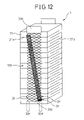
- FIG. 12 is a drawing to illustrate a constitution of a laminated-type piezoelectric element of another Embodiment of the present invention.
- the second external electrode layer 31 and the electrically conductive adhesive member 32 are disposed in a direction at a slant to a center line in the longitudinal direction of the first external electrode layer 33 .
- the second external electrode layer 31 and the electrically conductive adhesive member 32 is disposed in a shape of a line from one part (the upper left part in the Figure) which is one end of the first external electrode layer 33 in the longitudinal direction and one end of the first external electrode layer's end portion 33 c , which is one end of the first external electrode layer 33 in the width direction, to another part (the lower right part in the Figure) which is another end of the first external electrode layer 33 in the longitudinal direction and one end of the first external electrode layer's end portion 33 d , which is another end of the first external electrode layer 33 in the width direction.
- the first external electrode layer 33 can be fixed entirely in the longitudinal direction and in the width direction. Therefore, a part of the first external electrode layer 33 , which is not fixed to the electrically conductive adhesive member 32 , is hardly vibrated, and the first external electrode layer 33 is not peeled off, due to a vibration which the laminated-type piezoelectric element 1 receives from the outside.
- FIGS. 13( a ), 13 ( b ) are drawings to illustrate a constitution of a laminated-type piezoelectric element of another Embodiment of the present invention.
- the laminated-type piezoelectric element 1 shown in FIGS. 13( a ), 13 ( b ) is formed so as to make the width of the second external electrode layer 31 narrower than the width of the electrically conductive adhesive member 32 .
- the length of the second external electrode layer 31 is longer than the length of the electrically conductive adhesive member 32 .
- the length of the second external electrode layer 31 (not shown in the Figure) is equal to the length of the electrically conductive adhesive member 32 .
- the length of the second external electrode layer 31 (not shown in the Figure) is shorter than the length of the electrically conductive adhesive member 32 .
- the electrically conductive adhesive member 32 of which a coefficient of thermal expansion is larger than for the second external electrode layer 31 , is contracted in the width direction during at a low temperature, an end portion of the contracted electrically conductive adhesive member 32 is caught on an end portion of the second external electrode layer 31 . Therefore, peeling and breaking do not easily occur, and the adhering strength thereof is high.
- the second external electrode layer 31 and the electrically conductive adhesive member 32 are equal in length, and a distance to an end portion of the laminated-type piezoelectric element 1 in the stacking direction can be increased. Therefore, when a metal component exists at an end portion of the laminated-type piezoelectric element 1 in the stacking direction, its electrical insulation can be improved. Further, in the laminated-type piezoelectric element 1 shown in FIG. 13( c ), when the electrically conductive adhesive member 32 , of which the coefficient of thermal expansion is larger than for the second external electrode layer 31 , contracted in the width direction and in the longitudinal direction during at a low temperature, an end portion on the contracted electrically conductive adhesive member 32 is caught on an end portion of the second external electrode layer 31 .
- the electrical conductivity for the internal electrode layers 21 a and 21 b can be secured by a part of the first external electrode layer 33 which is not fixed to the electrically conductive adhesive member 32 , even when a part of the first external electrode layer 33 fixed to the electrically conductive adhesive member 32 was broken.
- the electrical conductivity for the internal electrode layers 21 a and 21 b can be secured by the side forming at least one opening portion 33 a.
- FIG. 14 is a drawing to illustrate a constitution of a laminated-type piezoelectric element of another Embodiment of the present invention.
- the laminated-type piezoelectric element 1 of this Embodiment comprise no opening portion 33 a at an end portion of the first external electrode layer 33 in the stacking direction and in the perpendicular direction of the laminated-type piezoelectric element 1 .
- opening portions approximate in the shape of a quadrangle are formed by making a notch at a first external electrode layer composed of stainless steal, copper, silver, iron, nickel or an alloy thereof, and stretching it.
- the first external electrode layer obtained on a thin plate is then cut into pieces with a desired width, and utilized.
- the electrical conductivity for the internal electrode layers 21 a and 21 b can be secured by a part of the first external electrode layer 33 which is not fixed to the electrically conductive adhesive member 32 , even when a part of the first external electrode layer 33 fixed to the electrically conductive adhesive member 32 was broken.
- the electrical conductivity for the internal electrode layers 21 a and 21 b can be secured by the side forming at least one opening portion 33 a.
- FIGS. 15( a )- 15 ( c ) are drawings to illustrate a constitution of a laminated-type piezoelectric element of another Embodiment of the present invention.
- the opening portions 33 a are in a shape of a circle.
- the opening portions 33 a are in a shape of an ellipse.
- the opening portions 33 a are in a shape of a quadrangle rounded at the corners.
- breaking of the first external electrode layer can be limited.
- the shape of the opening portions 33 a can be redesigned as appropriate to a triangle, a hexagon, an octagon and the like.
- the electrical conductivity for the internal electrode layers 21 a and 21 b can be secured by a part of the first external electrode layer 33 which is not fixed to the electrically conductive adhesive member 32 , even when a part of the first external electrode layer 33 fixed to the electrically conductive adhesive member 32 was broken.
- the electrical conductivity for the internal electrode layers 21 a and 21 b can be secured by the side forming at least one opening portion 33 a.
- the electrically conductive adhesive member 32 connecting the laminated-type piezoelectric element 1 and the first external electrode layer 33 penetrates into the opening portions of the first external electrode layer 33 to form connections in the shape of an anchor. Therefore, the first external electrode layer 33 connects firmly to the laminated-type piezoelectric element 1 . Further, the width Ws of the electrically conductive adhesive members 32 is narrower than the width Wm of the first external electrode layers 33 .
- the electrical conductivity for the internal electrode layers 21 a and 21 b can be secured by a part of the first external electrode layer 33 which is not fixed to the electrically conductive adhesive member 32 .
- the electrical conductivity for the internal electrode layers 21 a and 21 b can be secured by the side forming at least one opening portion 33 a .
- the laminated-type piezoelectric element 1 can be provided, where a connecting strength between the internal electrode layers 21 a , 21 b formed at the laminated-type piezoelectric element 1 and the first external electrode layer 33 is high, and displacement properties do not easily change even if a part of the first external electrode layer 33 was broken.
- the piezoelectric layers 11 are not limited to in the shape of a quadrangle, and may be in the shape of a polygon such as an octagon and the like.
- FIG. 16 is a drawing to illustrate a constitution of an example where a laminated-type piezoelectric element of the present invention is utilized to a common rail-type injection system of a diesel engine.
- an injector 5 has an upper housing 52 where the above-mentioned laminated-type piezoelectric element 1 is installed as a driving part, and a lower housing 53 fixed to the lower end of the upper housing where an injection nozzle portion 54 is formed internally.
- the upper housing 52 is in a shape of an approximately circular cylinder, and the laminated-type piezoelectric element 1 is inserted and fixed inside of a longitudinal hole 521 which is away from the center axis.
- a high-pressure fuel passage 522 is placed in parallel, and the upper end thereof is provided with a communication passage through a fuel introduction pipe 523 , which protrudes at upper side of the upper housing 52 , to an external common rail (omitted in the Figure).
- the upper housing 52 is also protrudingly provided with a fuel outflow pipe 525 with a communication passage to a drain passage 524 , and fuel flowing out from the fuel outflow pipe 525 is returned to a fuel tank (omitted in the Figure).
- the drain passage 524 is provided with a communication passage through a gap 50 between the longitudinal hole 521 and the driving part (the laminated-type piezoelectric element) 1 to a three-way valve 551 described later via a passage (omitted in the Figure) stretching from this gap 50 downwards in the upper housing 52 and the lower housing 53 .
- the injection nozzle portion 54 is provided with a nozzle needle 541 sliding up or down in a piston body 531 , and a injection slot 543 injecting the high-pressure fuel, which is supplied from a fuel reservoir 542 opened/closed by the nozzle needle 541 , to each cylinder of the engine.
- the fuel reservoir 542 is equipped on the periphery of the middle portion of the nozzle needle 541 , and a bottom end portion of the high-pressure fuel passage 522 is opened there.
- the nozzle needle 541 receives fuel pressure in the valve-opening direction from the fuel reservoir 542 , and also receives fuel pressure in the valve-closing direction from a back pressure chamber 544 provided facing the upper end area. When the pressure of the back pressure chamber 544 decreases, the nozzle needle 541 lifts, the injection slot 543 is opened, and the fuel is injected.
- the pressure of the back pressure chamber 544 is increased or decreased by the three-way valve 551 .
- the three-way valve 551 is configured so as to be selectively provided with a communication passage with the back pressure chamber 544 and the high-pressure fuel passage 522 or the drain passage 524 .
- a valve member in the shape of a ball which opens or closes a port with a communication passage to the high-pressure fuel passage 522 or the drain passage 524 is disposed here. This valve member is driven by the driving part 1 via a piston 552 with a large diameter disposed at a lower position of the driving part, an oil pressure chamber 553 and a piston 554 with a small diameter.
- Characteristic of the laminated-type piezoelectric element 1 in this Embodiment is that the electrically conductive adhesive member 32 connecting the laminated-type piezoelectric element 1 and the first external electrode layer 33 penetrates into the opening portions of the first external electrode layer 33 to form connections in the shape of an anchor. Therefore, the first external electrode layer 33 is firmly connected to the laminated-type piezoelectric element 1 even in a severe environment such as for the injector 5 . Further, the width Ws of the electrically conductive adhesive members 32 is narrower than the width Wm of the first external electrode layers 33 .
- the laminated-type piezoelectric element 1 for the injector which can be utilized with a high reliability under a severe environment, can be provided.
Landscapes
- Fuel-Injection Apparatus (AREA)
- General Electrical Machinery Utilizing Piezoelectricity, Electrostriction Or Magnetostriction (AREA)
Abstract
A laminated-type piezoelectric element 1 is provided, which comprises a first external electrode layer 33, which is located at a side area of the laminated-type piezoelectric element 1, is electrically continuous to internal electrode layers 21, and comprises plural expansible and contractible opening portions 33 a in a stacking direction of the laminated-type piezoelectric element 1. As the first external electrode layer 33 is connected to the laminated-type piezoelectric element 1 with an electrically conductive adhesive member 32 and the electrically conductive adhesive member 32 is narrower than the first external electrode layer 33, the electrically conductive adhesive member 32 penetrates into the opening portions 33 a of the first external electrode layer 33 to form connections in a shape of an anchor. Therefore, the first external electrode layer 33 is firmly connected to the laminated-type piezoelectric element 1.
Description
The present invention relates to a laminated-type piezoelectric element utilized in, for example, an injection valve for injecting fuel in an automobile, a finely-positioning device of an optical device and the like, a driving element for preventing vibration, and an ink-jet printer.
In recent years, in order to secure a large amount of displacement in an small piezoelectric actuator under a high pressure, a strong electric field has been applied to the piezoelectric actuator and it has been continuously driven or a long period.
In a laminated-type piezoelectric element utilized in such a piezoelectric actuator, when it has been continuously driven under a strong electric field and a high pressure for a long period, external electrodes for a positive electrode and a negative electrode disposed at side areas of the laminated-type piezoelectric element cannot follow movements of expansion and contraction of the laminated-type piezoelectric element. Therefore, peeling occurs between the internal electrode formed between piezoelectric bodies and the external electrode, or a crack occurs at the external electrode and the external electrode breaks. Thereby, a problem occurs where an electric voltage is not supplied to a part of the piezoelectric body, and the displacement properties change during driving.
Therefore, Japanese unexamined patent publication No. 8-242025 proposes a laminated-type piezoelectric element wherein a thin sheet of an electrically conductive material, where a notch was formed in a width direction, is connected to a side area of the laminated-type piezoelectric element with an electrically conductive adhesive so as to make the thin sheet of an electrically conductive material electrically continuous with an internal electrode.
However, in the prior art described in Japanese unexamined patent publication No. 8-242025, as the laminated-type piezoelectric element and the thin sheet of an electrically conductive material are connected by the electrically conductive adhesive of which the connecting strength is generally weak in comparison with soldering or brazing, there has been a problem where the connecting strength and its durability are inferior. Although the connection has an effect on a stress applied to the notch portion formed on the thin sheet of an electrically conductive material, the stress cannot be sufficiently reduced, and the thin sheet of an electrically conductive material breaks because the other parts than the notch portion are fixed with the electrically conductive adhesive. Further, as the electrical conductivity between the thin sheet of an electrically conductive material and the internal electrode cannot be secured due to the breaking of the thin sheet of an electrically conductive material, there is a problem where the displacement properties change during driving. The present invention has been achieved of by considering such problems. A purpose of the present invention is to provide a laminated-type piezoelectric element which offers an effect that the connecting strength between the internal electrode formed in the piezoelectric body and the external electrode is high even if an electrically conductive adhesive is utilized, and displacement properties do not easily change during driving even if a part of the external electrode breaks.
The present invention provides a laminated-type piezoelectric element, comprising piezoelectric layers composed of a ceramic being expansible and contractible by an applied electric voltage, internal electrode layers which are stacked alternately with the piezoelectric layers to form the laminated-type piezoelectric element and to supply the electric voltage to the piezoelectric layers, and first external electrode layers which are disposed on side areas of the laminated-type piezoelectric element, are electrically continuous to the internal electrode layers, and comprise plural opening portions being expansible and contractible in a stacking direction of the laminated-type piezoelectric element, wherein the first external electrode layer is connected to the laminated-type piezoelectric element via an electrically conductive adhesive member, and a width of the electrically conductive adhesive member is narrower than a width of the first external electrode layer.
Thereby, although an adhering strength of the electrically conductive adhesive member is generally weak in comparison with soldering or brazing, the first external electrode layer strongly connects to the laminated-type piezoelectric element, as the electrically conductive adhesive member penetrates into the opening portion of the first external electrode layer to form a connection in the shape of an anchor. Further, as the width of the electrically conductive adhesive member is narrower than the width of the first external electrode layer, the electrical conductivity for the internal electrode layers can be secured by a part of the first external electrode layer which is not fixed to the electrically conductive adhesive member, even when a part of the first external electrode layer fixed to the electrically conductive adhesive member is broken by a displacement of the piezoelectric layers and the like. Therefore, the laminated-type piezoelectric element can be provided, where the connecting strength between the internal electrode layers formed at the laminated-type piezoelectric element and the first external electrode layer is high, and the displacement properties do not easily change even if a part of the first external electrode layer was broken.
According to the present invention of claim 2, the laminated-type piezoelectric element is provided, where the width of the electrically conductive adhesive member is not less than 0.3 mm. Thereby, the connecting strength is sufficiently high for the laminated-type piezoelectric element, even if the adhesive with the adhering strength of not greater than 20 MPa.
According to the invention of claim 3, the laminated-type piezoelectric element is provided, where a maximum width of the opening portion in a perpendicular direction to the stacking direction of the laminated-type piezoelectric element is not greater than 0.5 Wm, wherein Wm represents the width of the first external electrode layer. Thereby, the electrical conductivity to the internal electrode layers can be secured by a part of the first external electrode layer which is not fixed to the electrically conductive adhesive member, even when a part of the first external electrode layer fixed to the electrically conductive adhesive member is broken. In other words, the electrical conductivity to the internal electrode layers can be secured by a side forming at least one opening portion.
According to the invention of claim 4, the laminated-type piezoelectric element is provided, where a shape of the opening portion is a circle or an ellipse. Thereby, the first external electrode layer seldom breaks because the opening portion has a shape with no angle where a stress due to the displacement of the piezoelectric layers and the like does not easily concentrate.
According to the invention of claim 5, the laminated-type piezoelectric element is provided, where a shape of the opening portion is a polygon rounded at corners. Thereby, the first external electrode layer seldom breaks because the opening portion has a rounded shape where a stress due to the displacement of the piezoelectric layers and the like does not easily concentrate.
According to the invention of claim 6, the laminated-type piezoelectric element is provided, where a shape of the opening portion is a quadrangle or a lozenge, further especially where a width Ws of the electrically conductive adhesive member is represented by the following formula,
Ws<Wm−h
wherein Wm represents a width of the first external electrode layer, and h represents a height of a triangle with three sides of “a”, “b” and “L2”, wherein “a” and “b” represent respectively lengths of two sides adjoining to each other in the stacking direction at the opening portion formed in the shape of a quadrangle or a lozenge, and “L2” represents a width of the opening portion in the stacking direction of the laminated-type piezoelectric element. Thereby, the electrical conductivity for the internal electrode layers can be secured by a part of the first external electrode layer which is not fixed to the electrically conductive adhesive member, even when a part of the first external electrode layer fixed to the electrically conductive adhesive member is broken by a displacement of the piezoelectric layers. In other words, the electrical conductivity to the internal electrode layers can be secured by the side of “a” and the side of “b” forming at least one opening portion.
According to the invention of claim 8, the laminated-type piezoelectric element is provided, where a relation among three sides of the triangle is represented by the following formula,
a+b>L 2×α
wherein α represents an extensibility (maximum extension/total length) of the laminated-type piezoelectric element in the stacking direction. Thereby, the first external electrode layer cannot be easily broken by the extension of the piezoelectric body, because of the relation a+b>L2×α.
a+b>L 2×α
wherein α represents an extensibility (maximum extension/total length) of the laminated-type piezoelectric element in the stacking direction. Thereby, the first external electrode layer cannot be easily broken by the extension of the piezoelectric body, because of the relation a+b>L2×α.
Further, according to the invention of claim 9, it is preferred that a maximum extensibility (maximum extension/total length) of the laminated-type piezoelectric element in the stacking direction is not greater than 0.012.
According to the invention of claim 10, the laminated-type piezoelectric element is provided, where the first external electrode layer is composed of a metal composed of at least one metal selected from stainless steel, copper, silver, iron and nickel, or an alloy thereof. Thereby, the first external electrode layer with the high strength can be formed.
Further, according to the invention of claim 11, the laminated-type piezoelectric element is provided, wherein a non-opening portion, where the opening portion is not formed, is formed at an end portion of the first external electrode layer. Thereby, the connection with an outer device can be made easy.
According to the invention of claim 12, the laminated-type piezoelectric element is provided, wherein a second external electrode layer intervenes between the electrically conductive adhesive member and the first external electrode layer, especially wherein the second external electrode layer is composed of a metal composed of at least one metal selected from silver, palladium, platinum, copper, gold and nickel, or an alloy thereof. Thereby, a thermal stress applied from the piezoelectric layers to the first external electrode layer can be decreased in comparison with a case where the first external electrode layer is directly connected to the piezoelectric layers, because a coefficient of thermal expansion of the second external electrode layer is between the coefficients of thermal expansion of the piezoelectric layer and the first external electrode layer, and functions as a layer for the relaxation of a thermal stress.
According to the invention of claim 14, the laminated-type piezoelectric element is provided, wherein an insulating resin member intervenes in a gap between the first external electrode layer and the internal electrode layer, which is formed so that the width of the electrically conductive adhesive member is narrower than the width of the first external electrode layer, especially wherein the insulating resin member is composed of a silicone resin, an epoxy resin, a urethane resin, a polyimide resin, a polyamideimide resin or a polyester resin. Thereby, phenomena of electrical discharge caused by repeating electrical conductivity between the first external electrode layer and the internal electrode layer can be prevented, because an electrical insulation can be formed between the first external electrode layer and the internal electrode layer there.
According to the present invention of claim 16, the laminated-type piezoelectric element is provided, where the laminated-type piezoelectric element is formed by connecting laminated-type piezoelectric units. Even in such a manner, the present invention can provides the laminated-type piezoelectric element where the connecting strength between the internal electrode layers formed in the laminated-type piezoelectric element and the first external electrode layer is high, and displacement properties do not easily change even if a part of the first external electrode layer was broken.
If the laminated-type piezoelectric element is utilized for a fuel injection device according to the present invention of claim 17, the fuel injection device with an excellent durability can be provided, because the connecting strength between the internal electrode layers formed in the laminated-type piezoelectric element and the first external electrode layer is high, and displacement properties do not easily change even if a part of the first external electrode layer was broken.
(Summary)
A constitution of an Embodiment of the first present invention is illustrated as follows according to Figures. FIG. 1 is a drawing to illustrate a constitution of a laminated-type piezoelectric element of the Embodiment of the present invention. As shown in FIG. 1 , the laminated-type piezoelectric element 1 of this Example comprises, divided broadly, piezoelectric layers 11, internal electrode layers 21 a and 21 b, second external electrode layers 31, electrically conductive adhesive members 32, first external electrode layers 33 and insulating resin members 34, and is constituted as follows. The laminated-type piezoelectric element 1 is formed by stacking alternately plural piezoelectric layers 11 composed of a ceramic material PZT expansible and contractible by an applied electric voltage and plural internal electrode layers 21 for supplying the applied electric voltage. On external periphery side areas 101, the second external electrode layers 31 being electrically continuous are disposed so that the internal electrode layers 21 a and the internal electrode layers 21 b become different electrodes respectively. On the second external electrode layer 31, the first external electrode layer 33 is formed through the electrically conductive adhesive member 32. The first external electrode layer 33 comprises plural expansible and contractible opening portions 33 a. Further, the insulating resin member 34 intervenes between the external periphery side area 101 and the first external electrode layer 33 of the laminated-type piezoelectric element 1, and prevents phenomena of a spark discharge caused by repeating electrical conductivity between the first external electrode layer 33 and the internal electrode layers 21 a, 21 b.
Characteristic parts in the present invention are then illustrated as follows. The first external electrode layer 33 comprises the plural expansible and contractible opening portions 33 a. As the electrically conductive adhesive member 32 can penetrate into the opening portions 33 a of the first external electrode layer 33 and form connections in the shape of an anchor, the second external electrode layer 31 and the first external electrode layer 33 are strongly connected, even if an electrically conductive adhesive generally having a weak connecting strength, in comparison with soldering or brazing, is used. As the width of the electrically conductive adhesive member 32 is narrower than the width of the first external electrode layer 33, the electrical conductivity for the internal electrode layers 21 a and 21 b can be secured by a part of the first external electrode layer 33 which is not fixed to the electrically conductive adhesive members 32, even when a part of the first external electrode layer 33 fixed to the electrically conductive adhesive members 32 was broken by the displacement of the piezoelectric layers and the like. Therefore, the laminated-type piezoelectric element can be provided, where the connecting strength between the internal electrode layers 21 a, 21 b formed at the piezoelectric layers 11 and the first external electrode layer 33 is high, and displacement properties do not easily change even if a part of the first external electrode layer 33 was broken.
(Details)
The details of the present invention are described as follows. As shown in FIG. 1 , the laminated-type piezoelectric element 1 is formed so that the internal electrode layers 21 a and 21 b can be made alternately positive and negative between the piezoelectric layers 11. The internal electrode layers 21 a are disposed so as to be exposed at one external periphery side area 101, while the internal electrode layers 21 b are disposed so as to be exposed at the other external periphery side area (not shown in FIG. 1 ). At the external periphery side areas 101 of the laminated-type piezoelectric element 1, the second external electrode layers 31 composed of a baked silver are formed so as to make end portions of the exposed internal electrode layers 21 electrically continuous. The baked silver configuring the second external electrode layer 31 is an electrode made by baking an Ag paste, and has a composition including Ag at 97% and a glass-frit component at 3%. The second external electrode layer 31 can be formed by vapor-deposition or plating, and not by baking.
On the second external electrode layer 31, the first external electrode layer 33 is disposed through the electrically conductive adhesive member 32. The electrically conductive adhesive member 32 and the first external electrode layer 33 are further described later.
At the first external electrode layer 33, a non-opening portion 33 b for supplying the applied electric voltage from outside to the laminated-type piezoelectric element 1 is formed. Further, a part for connecting with an outer electric source, which corresponds to the non-opening portion 33 b, can be varied as appropriate based on a design, and may be formed, for example, at the second external electrode layers 31.
In the laminated-type piezoelectric element 1, a central part in the stacking direction was formed as a driving portion 11 a, parts sandwiching the driving portion 11 a were formed as buffer portions 11 b, and parts sandwiching the buffer portions 11 b were further formed as dummy portions 11 c. Thereby, they are configured so that an amount of expansion and contraction decreases, during application of an electric voltage, in order of the driving portion 11 a, the buffer portion 11 b and the dummy portion 11 c. Concretely, the thicknesses of the piezoelectric layers 11 are made thicker in order, and the internal electrode layer is not formed at an upper area of the upper dummy portion 11 c and a lower area of the lower dummy portion 11 c. Thus, as internal stresses can be relaxed in stages, a crack is not easily formed, and the laminated-type piezoelectric element 1 can be used for a long period.
A manufacturing method and a detailed structure of this laminated-type piezoelectric element 1 are explained as follows. The laminated-type piezoelectric element 1 of this Example can be manufactured by utilizing a green-sheet method which is widely used. Powders of lead oxide, zirconium oxide, titanium oxide, niobium oxide, strontium oxide or the like, which becomes a main source of a piezoelectric material, are weighed to make a desired composition. Considering vaporization of the lead, the lead oxide is formulated so as to enrich it at 1-2% more than a stoichiometric ratio of the mixed composition. The composition is dry-mixed with a mixer, and then is partly calcined at 800-950° C.
Water and a dispersant are added to the partly calcined powder to make slurry, and then the slurry is water-ground with a purl-mill. After that, the ground slurry is deaerated in a vacuum device, while being stirred, to adjust its viscosity.
A green sheet with a uniform thickness is then formed from the slurry, using a doctor-blade device. The obtained green sheet is punched with a pressing machine, or is cut by a cutting machine to form pieces of a specified size. The green sheet is utilized commonly for the driving portion, the buffer portion and the dummy portion.
A pattern is formed on one surface of the formed green sheet by screen-printing, for example, with a paste of silver and palladium having a silver/palladium ratio of 7/3 by weight (herein after referred to as Ag/Pd paste).
On an approximately entire surface of the green sheet to become the piezoelectric layer 11, a relatively smaller pattern than a surface of the piezoelectric layer 11 is formed with the Ag/Pd paste to obtain the internal electrode layers 21 a and 21 b. At one side of opposing sides of the surface of the green sheet, a portion is disposed where the internal electrode layer 21 a (21 b) is not formed. In other words, the portion is disposed so that the internal electrode layer 21 a (21 b) does not reach to one end portion of opposing sides of the surface of the green sheet (a part corresponding to one side area 101 or an opposing area of the laminated-type piezoelectric element 1), while the internal electrode layer 21 a (21 b) can reach to the other end portion of the opposing sides.
A specified number of the green sheets, on which such internal electrode layers 21 a and 21 b were formed, are prepared for the driving portion 11 a and the buffer portion 11 b, based on a required specification of an amount of the displacement. A necessary number of the green sheets, on which an internal electrode layer is not printed, also are prepared for the buffer portion 11 b and the dummy portion 11 c.
These green sheets are then stacked. When the green sheets, where electrode layers 21 a and 21 b were formed, are stacked, they are stacked so that portions where no electrode was formed can be disposed alternately at one side area 101 and the opposing side area of the laminated-type piezoelectric element 1. Thereby, the internal electrode layer 21 a exposed at one side area 101 of the green sheet becomes an internal electrode for one pole at the side area, while the internal electrode layer 21 b exposed at the opposing side area becomes an internal electrode for another pole at the opposing side.
The central driving portion 11 a is formed by stacking only green sheets where the internal electrode layers 21 a and 21 b were formed, the buffer portions 11 b are formed by stacking green sheets via intervening a green sheet, where no internal electrode was formed, between green sheets, and the dummy portions 11 c are formed by stacking only green sheets where no internal electrode was formed. Thereby, a laminate body with a structure shown in FIG. 1 is obtained.
Next, after thermally bonding in a press, by rubber-pressing with warm water and the like, the laminate body is degreased at 400-700° C. using an electric oven, and is calcined at 900-1200° C. The second external electrode layer 31 is then formed by applying and baking the Ag paste on the side area of the laminate body. Although the second external electrode layer 31 was formed using the baked Ag in this Example, it also may be formed by baking, for example, a paste of Ag/Pd, Pt, Cu, Ni, Au or the like. Silver, copper, nickel, platinum, gold and the like other than the above-mentioned materials may be utilized as a material for the internal electrode layers 21 a and 21 b.
The second external electrode layer 31 is formed at a position where the internal electrode layers 21 a for one pole are exposed, to make electrical conductivity with each internal electrode layer 21 a. The second external electrode layer 31 disposed on the opposing side area (not shown in the Figure) is formed at a position, where the internal electrode layers 21 b for another pole are exposed, to make electrical conductivity with each of the internal electrode layers 21 b. The electrically conductive adhesive members 32 are then applied on the second external electrode layers 31. The first external electrode layers 33 are pressed to the electrically conductive adhesive members 32. The laminated-type piezoelectric element 1 is then immersed into an insulating oil, and a direct electric current is applied between the internal electrode layers 21 a and 21 b from the non-opening portion 33 b of the first external electrode layer 33 to polarize the piezoelectric layers 11. Thus, the laminated-type piezoelectric element 1 is obtained.
(Characterized portions of the present invention)
The first external electrode layers 33 is composed of stainless steel, copper, iron, nickel or an alloy thereof, and is formed with the opening portions 33 a in a shape of a lozenge. As a method for forming the opening portions 33 a, a punching process, an etching process, a laser process, a method for forming a sheet in a shape of a lattice by making a notch at a metal plate and stretching the plate or the like can be utilized. At an end portion of the first external electrode layer 33, the non-opening portion 33 b is formed, where no opening portion is formed.
The insulating resin members 34 is composed of a silicone resin, an epoxy resin, a urethane resin, a polyimide resin, a polyamideimide resin or a polyester resin, and is formed between the internal electrode layers 21 a, 21 b and the first external electrode layers 33 disposed in the laminated-type piezoelectric element 1 to prevent phenomena of a spark discharge caused by repeated electrical conductivity between the first external electrode layer 33 and the internal electrode layers 21 a, 21 b.
Ws<Wm−h
Thereby, the electrical conductivity for the internal electrode layers 21 a and 21 b can be secured by a part of the first external electrode layer 33 which is not fixed to the electrically conductive adhesive member 32, even when a part of the first external electrode layer 33 fixed to the electrically conductive adhesive member 32 was broken. In other words, the electrical conductivity for the internal electrode layers 21 a and 21 b can be secured by the sides of “a” and “b” forming at least one opening portion 33 a.
Further, when a represents extensibility (maximum extension/total length) of the laminated-type piezoelectric element 1 in the stacking direction, a relation among three sides of the triangle is represented by the following formula.
a+b>L 2×α
a+b>L 2×α
Thereby, the first external electrode layer 33 cannot be easily broken by the extension of the laminated-type piezoelectric element 1. The extensibility of the laminated-type piezoelectric element 1 in this Embodiment is approximately in a range of 0.001-0.002. In other words, for example, when a total length of the laminated-type piezoelectric element 1 is 50 mm, and the maximum extension is 0.05 mm, the extensibility is 0.001. The extensibility of the laminated-type piezoelectric element 1 is not limited by this Example. When the extensibility of the laminated-type piezoelectric element 1 is not greater than 0.012, it is thought that the first external electrode layer 33 is not easily broken by the extension of the laminated-type piezoelectric element 1.
When Wm represents the width of the first external electrode layer 33, the width of the opening portion 33 a in a perpendicular direction to the stacking direction of the laminated-type piezoelectric element 1 is not greater than 0.5 Wm. Thereby, even if one opening portion 33 a formed at the first external electrode layer 33 is fixed with the electrically conductive adhesive member 32, the other opening portion 33 a can be made in a state of not being fixed with the electrically conductive adhesive member 32. Therefore, the electrical conductivity for the internal electrode layers 21 a and 21 b can be secured by a part of the first external electrode layer 33 which is not fixed to the electrically conductive adhesive member 32, even when a part of the first external electrode layer 33 fixed to the electrically conductive adhesive member 32 was broken. In other words, the electrical conductivity for the internal electrode layers 21 a and 21 b can be secured by the side forming at least one opening portion 33 a.
As mentioned above, in this Embodiment, the electrically conductive adhesive member 32 penetrats into the opening portions 33 a of the first external electrode layer 33 to form the connection in the shape of an anchor, in order to connect the laminated-type piezoelectric element 1 and the first external electrode layer 33. Therefore, the first external electrode layer 33 is firmly connected to the laminated-type piezoelectric element 1. Further, the width Ws of the electrically conductive adhesive members 32 is narrower than the width Wm of the first external electrode layers 33. Therefore, the electrical conductivity for the internal electrode layers 21 a and 21 b can be secured by a part of the first external electrode layer 33 which is not fixed to the electrically conductive adhesive member 32, even when a part of the first external electrode layer 33 fixed to the electrically conductive adhesive member 32 was broken by the displacement of the piezoelectric layers 11 and the like. In other words, the electrical conductivity for the internal electrode layers 21 a and 21 b can be secured by an effect of the side forming at least one opening portion 33 a. Thus, the laminated-type piezoelectric element 1 can be provided, where a connecting strength between the internal electrode layers 21 a, 21 b formed at the laminated-type piezoelectric element 1 and the first external electrode layer 33 is high, and displacement properties do not easily change even if a part of the first external electrode layer 33 is broken.
In the laminated-type piezoelectric elements 1 shown in FIG. 11 and FIG. 12 , the first external electrode layer 33 can be fixed entirely in the longitudinal direction and in the width direction. Therefore, a part of the first external electrode layer 33, which is not fixed to the electrically conductive adhesive member 32, is hardly vibrated, and the first external electrode layer 33 is not peeled off, due to a vibration which the laminated-type piezoelectric element 1 receives from the outside.
As mentioned above, in this Embodiment, the electrically conductive adhesive member 32 connecting the laminated-type piezoelectric element 1 and the first external electrode layer 33 penetrates into the opening portions of the first external electrode layer 33 to form connections in the shape of an anchor. Therefore, the first external electrode layer 33 connects firmly to the laminated-type piezoelectric element 1. Further, the width Ws of the electrically conductive adhesive members 32 is narrower than the width Wm of the first external electrode layers 33. Therefore, even when a part of the first external electrode layer 33 fixed to the electrically conductive adhesive member 32 was broken by displacements of the piezoelectric layers 11 and the like, the electrical conductivity for the internal electrode layers 21 a and 21 b can be secured by a part of the first external electrode layer 33 which is not fixed to the electrically conductive adhesive member 32. In other words, the electrical conductivity for the internal electrode layers 21 a and 21 b can be secured by the side forming at least one opening portion 33 a. Therefore, the laminated-type piezoelectric element 1 can be provided, where a connecting strength between the internal electrode layers 21 a, 21 b formed at the laminated-type piezoelectric element 1 and the first external electrode layer 33 is high, and displacement properties do not easily change even if a part of the first external electrode layer 33 was broken.
The constitutions utilized in the present invention are not limited to these Embodiments, if they can resolve the problems for the present invention. For example, the piezoelectric layers 11 are not limited to in the shape of a quadrangle, and may be in the shape of a polygon such as an octagon and the like.
The upper housing 52 is in a shape of an approximately circular cylinder, and the laminated-type piezoelectric element 1 is inserted and fixed inside of a longitudinal hole 521 which is away from the center axis. At the side of the longitudinal hole 521, a high-pressure fuel passage 522 is placed in parallel, and the upper end thereof is provided with a communication passage through a fuel introduction pipe 523, which protrudes at upper side of the upper housing 52, to an external common rail (omitted in the Figure).
The upper housing 52 is also protrudingly provided with a fuel outflow pipe 525 with a communication passage to a drain passage 524, and fuel flowing out from the fuel outflow pipe 525 is returned to a fuel tank (omitted in the Figure). The drain passage 524 is provided with a communication passage through a gap 50 between the longitudinal hole 521 and the driving part (the laminated-type piezoelectric element) 1 to a three-way valve 551 described later via a passage (omitted in the Figure) stretching from this gap 50 downwards in the upper housing 52 and the lower housing 53.
The injection nozzle portion 54 is provided with a nozzle needle 541 sliding up or down in a piston body 531, and a injection slot 543 injecting the high-pressure fuel, which is supplied from a fuel reservoir 542 opened/closed by the nozzle needle 541, to each cylinder of the engine. The fuel reservoir 542 is equipped on the periphery of the middle portion of the nozzle needle 541, and a bottom end portion of the high-pressure fuel passage 522 is opened there. The nozzle needle 541 receives fuel pressure in the valve-opening direction from the fuel reservoir 542, and also receives fuel pressure in the valve-closing direction from a back pressure chamber 544 provided facing the upper end area. When the pressure of the back pressure chamber 544 decreases, the nozzle needle 541 lifts, the injection slot 543 is opened, and the fuel is injected.
The pressure of the back pressure chamber 544 is increased or decreased by the three-way valve 551. The three-way valve 551 is configured so as to be selectively provided with a communication passage with the back pressure chamber 544 and the high-pressure fuel passage 522 or the drain passage 524. A valve member in the shape of a ball which opens or closes a port with a communication passage to the high-pressure fuel passage 522 or the drain passage 524 is disposed here. This valve member is driven by the driving part 1 via a piston 552 with a large diameter disposed at a lower position of the driving part, an oil pressure chamber 553 and a piston 554 with a small diameter.
Characteristic of the laminated-type piezoelectric element 1 in this Embodiment is that the electrically conductive adhesive member 32 connecting the laminated-type piezoelectric element 1 and the first external electrode layer 33 penetrates into the opening portions of the first external electrode layer 33 to form connections in the shape of an anchor. Therefore, the first external electrode layer 33 is firmly connected to the laminated-type piezoelectric element 1 even in a severe environment such as for the injector 5. Further, the width Ws of the electrically conductive adhesive members 32 is narrower than the width Wm of the first external electrode layers 33. Therefore, even when a part of the first external electrode layer 33 fixed to the electrically conductive adhesive member 32 was broken by displacements of the piezoelectric layers 11 and the like, the electrical conductivity for the internal electrode layers 21 a and 21 b can be secured by a part of the first external electrode layer 33 which is not fixed to the electrically conductive adhesive member 32, and the reliability of the laminated-type piezoelectric element 1 is high. Thus, the laminated-type piezoelectric element 1 for the injector, which can be utilized with a high reliability under a severe environment, can be provided.
Claims (20)
1. A laminated-type piezoelectric element, comprising
piezoelectric layers composed of a ceramic being expansible and contractible by an applied electric voltage,
internal electrode layers which are stacked alternately with the piezoelectric layers to form the laminated-type piezoelectric element, and supply the electric voltage to the piezoelectric layers, and
first external electrode layers which are disposed on side areas of the laminated-type piezoelectric element, are electrically continuous to the internal electrode layers, and comprise plural opening portions being expansible and contractible in a stacking direction of the laminated-type piezoelectric element,
wherein the first external electrode layer is connected to the laminated-type piezoelectric element via an electrically conductive adhesive member which has penetrated into the plural opening portions, and
a width of the electrically conductive adhesive member is narrower than a width of the first external electrode layer.
2. The laminated-type piezoelectric element according to claim 1 , wherein the width of the electrically conductive adhesive member is not less than 0.3 mm.
3. The laminated-type piezoelectric element according to claim 1 , wherein a maximum width of the opening portion in a perpendicular direction to the stacking direction of the laminated-type piezoelectric element is not greater than 0.5 Wm, wherein Wm represents the width of the first external electrode layer.
4. The laminated-type piezoelectric element according to claim 1 , wherein a shape of the opening portion is a circle or an ellipse.
5. The laminated-type piezoelectric element according to claim 1 , wherein a shape of the opening portion is a polygon rounded at the corners.
6. The laminated-type piezoelectric element according to claim 1 , wherein a shape of the opening portion is a quadrangle or a lozenge.
7. The laminated-type piezoelectric element according to claim 6 , wherein a width Ws of the electrically conductive adhesive member is represented by the following formula,
Ws<Wm−h
Ws<Wm−h
wherein Wm represents a width of the first external electrode layer, and h represents a height of a triangle with three sides of a, b and L2, wherein a and b represent respectively lengths of two sides adjoining to each other in the stacking direction at the opening portion formed in the shape of a quadrangle or a lozenge, and L2 represents a width of the opening portion in the stacking direction of the laminated-type piezoelectric element.
8. The laminated-type piezoelectric element according to claim 7 , wherein a relation among three sides of the triangle is represented by the following formula,
a+b>L 2×α
a+b>L 2×α
wherein α represents an extensibility (maximum extension/total length) of the laminated-type piezoelectric element in the stacking direction.
9. The laminated-type piezoelectric element according to claim 1 , wherein a maximum extensibility (maximum extension/total length) of the laminated-type piezoelectric element in the stacking direction is not greater than 0.012.
10. The laminated-type piezoelectric element according to claim 1 , wherein the first external electrode layer is composed of a metal composed of at least one metal selected from stainless steel, copper, silver, iron and nickel, or an alloy thereof.
11. The laminated-type piezoelectric element according to claim 1 , wherein a non-opening portion, where the opening portion is not formed, is formed at an end portion of the first external electrode layer.
12. The laminated-type piezoelectric element according to claim 1 , wherein a second external electrode layer intervenes between the electrically conductive adhesive member and the first external electrode layer.
13. The laminated-type piezoelectric element according to claim 12 , wherein the second external electrode layer is composed of a metal composed of at least one metal selected from silver, palladium, platinum, copper, gold and nickel, or an alloy thereof.
14. The laminated-type piezoelectric element according to claim 1 , wherein an insulating resin member intervenes in a gap between the first external electrode layer and the internal electrode layer, which is formed by that the width of the electrically conductive adhesive member is narrower than the width of the first external electrode layer.
15. The laminated-type piezoelectric element according to claim 14 , wherein the insulating resin member is composed of a silicone resin, an epoxy resin, a urethane resin, a polyimide resin, a polyamideimide resin or a polyester resin.
16. The laminated-type piezoelectric element according to claim 1 , wherein the laminated-type piezoelectric element is formed by connecting laminated-type piezoelectric units.
17. The laminated-type piezoelectric element according to claim 1 , wherein the laminated-type piezoelectric element is utilized for a fuel injection device.
18. The laminated-type piezoelectric element according to claim 1 , wherein electrically conductive adhesive member which has penetrated into the plural opening portions covers at least a portion of the first external electrode layer.
19. A laminated-type piezoelectric element, comprising
piezoelectric layers composed of a ceramic being expansible and contractible by an applied electric voltage,
internal electrode layers which are stacked alternately with the piezoelectric layers to form the laminated-type piezoelectric element, and supply the electric voltage to the piezoelectric layers, and
first external electrode layers which are disposed on side areas of the laminated-type piezoelectric element, are electrically continuous to the internal electrode layers, and comprise plural opening portions being expansible and contractible in a stacking direction of the laminated-type piezoelectric element,
wherein the first external electrode layer is connected to the laminated-type piezoelectric element via an electrically conductive adhesive member, and
a width of the electrically conductive adhesive member is narrower than a width of the first external electrode layer,
wherein a shape of the opening portions is a circle or an ellipse.
20. A laminated-type piezoelectric element, comprising
piezoelectric layers composed of a ceramic being expansible and contractible by an applied electric voltage,
internal electrode layers which are stacked alternately with the piezoelectric layers to form the laminated-type piezoelectric element, and supply the electric voltage to the piezoelectric layers, and
first external electrode layers which are disposed on side areas of the laminated-type piezoelectric element, are electrically continuous to the internal electrode layers, and comprise plural opening portions being expansible and contractible in a stacking direction of the laminated-type piezoelectric element,
wherein the first external electrode layer is connected to the laminated-type piezoelectric element via an electrically conductive adhesive member, and
a width of the electrically conductive adhesive member is narrower than a width of the first external electrode layer,
wherein a shape of the opening portions is a polygon rounded at the corners.
Applications Claiming Priority (2)
| Application Number | Priority Date | Filing Date | Title |
|---|---|---|---|
| JP2005120386A JP2006303044A (en) | 2005-04-18 | 2005-04-18 | Laminated piezoelectric material element |
| JP2005-120386 | 2005-04-18 |
Publications (2)
| Publication Number | Publication Date |
|---|---|
| US20060232172A1 US20060232172A1 (en) | 2006-10-19 |
| US7439655B2 true US7439655B2 (en) | 2008-10-21 |
Family
ID=37107842
Family Applications (1)
| Application Number | Title | Priority Date | Filing Date |
|---|---|---|---|
| US11/405,493 Expired - Fee Related US7439655B2 (en) | 2005-04-18 | 2006-04-18 | Laminated-type piezoelectric element |
Country Status (4)
| Country | Link |
|---|---|
| US (1) | US7439655B2 (en) |
| JP (1) | JP2006303044A (en) |
| CN (1) | CN1855567A (en) |
| DE (1) | DE102006000176A1 (en) |
Cited By (15)
| Publication number | Priority date | Publication date | Assignee | Title |
|---|---|---|---|---|
| US20070176521A1 (en) * | 2003-09-24 | 2007-08-02 | Shigenobu Nakamura | Multi-layer piezoelectric element |
| US20070296311A1 (en) * | 2006-06-22 | 2007-12-27 | Fujitsu Limited | Piezoelectric actuator and manufacturing method thereof, magnetic disk apparatus |
| US20080024043A1 (en) * | 2006-07-31 | 2008-01-31 | Oakley Charles D | Strain tolerant metal electrode design |
| US20080203851A1 (en) * | 2007-02-27 | 2008-08-28 | Iptrade, Inc. | Piezoelectric package with porous conductive layers |
| US20080203853A1 (en) * | 2005-07-26 | 2008-08-28 | Carsten Schuh | Method For Producing a Monolithic Piezo Actuator With Stack Elements, Monilithic Piezo Actuator With Stack Elements, and Use of the Piezo Actuator |
| US20080238264A1 (en) * | 2004-03-29 | 2008-10-02 | Kyocera Corporation | Multi-Layer Piezoelectric Element and Method for Manufacturing the Same |
| US20090000597A1 (en) * | 2006-02-09 | 2009-01-01 | Maximilian Kronberger | Piezoceramic Multilayer Actuator, Method for Producing a Piezoceramic Multilayer Actuator, and Inujection System |
| US20090127982A1 (en) * | 2007-11-14 | 2009-05-21 | Interplex Nas, Inc. | Planar spring assembly with attached solder strip and method for making same |
| US20090179527A1 (en) * | 2004-11-30 | 2009-07-16 | Michael Kaspar | Contacting multilayer piezo actuators or sensors |
| US20100097723A1 (en) * | 2008-10-21 | 2010-04-22 | Tdk Corporation | Thin-film piezoelectric device, production method thereof, head gimbals assembly using the thin-film piezoelectric device, and hard disk drive using the head gimbals assembly |
| US20100244636A1 (en) * | 2007-12-06 | 2010-09-30 | Stefan Denneler | Piezoelectric component with outer contacting, having gas-phase deposition, method for manufacturing the component and use of the component |
| US20100326405A1 (en) * | 2007-12-26 | 2010-12-30 | Kyocera Corporation | Multi-Layer Piezoelectric Element, and Injection Apparatus and Fuel Injection System that Employ the Same |
| US20110018401A1 (en) * | 2008-04-11 | 2011-01-27 | Murata Manufacturing Co., Ltd. | Multilayer Piezoelectric Actuator |
| US20120019107A1 (en) * | 2008-08-18 | 2012-01-26 | Epcos Ag | Piezo Actuator in Multi-Layered Construction |
| US20130074300A1 (en) * | 2010-05-06 | 2013-03-28 | Renault S.A.S. | Process for producing an actuator having a stack of alternating intermediate electrode layers and piezoelectric material layers |
Families Citing this family (22)
| Publication number | Priority date | Publication date | Assignee | Title |
|---|---|---|---|---|
| DE10234787C1 (en) * | 2002-06-07 | 2003-10-30 | Pi Ceramic Gmbh Keramische Tec | Manufacturing method for monolithic multi-layer piezoceramic actuator with microfaults provided in actuator joints parallel to inner electrodes |
| US7385337B2 (en) * | 2004-06-18 | 2008-06-10 | Tdk Corporation | Multilayer piezoelectric element |
| JP2007173320A (en) * | 2005-12-19 | 2007-07-05 | Denso Corp | Laminate piezoelectric element and its manufacturing method |
| CN101405882B (en) * | 2006-03-31 | 2011-06-15 | 株式会社村田制作所 | Piezoelectric actuator |
| JP4929875B2 (en) * | 2006-06-30 | 2012-05-09 | 株式会社デンソー | Multilayer piezoelectric element |
| JP2009123750A (en) | 2007-11-12 | 2009-06-04 | Denso Corp | Stacked piezoelectric device |
| US8899470B2 (en) * | 2007-11-29 | 2014-12-02 | Corning Incorporated | Method for bonding refractory ceramic and metal |
| EP2259353B1 (en) * | 2008-04-21 | 2012-06-27 | Murata Manufacturing Co. Ltd. | Multilayer piezoelectric actuator |
| DE102008056746A1 (en) | 2008-11-11 | 2010-05-12 | Epcos Ag | Multi-layer piezoelectric actuator and method for mounting an external electrode in a piezoelectric actuator |
| JP5377100B2 (en) * | 2009-06-16 | 2013-12-25 | 京セラ株式会社 | Multilayer piezoelectric element, injection device and fuel injection system using the same |
| CN101594069B (en) * | 2009-06-23 | 2011-07-27 | 南京航空航天大学 | Fold-shaped compound piezoelectric energy converting structure |
| JP5421390B2 (en) * | 2009-11-26 | 2014-02-19 | 京セラ株式会社 | Multilayer piezoelectric element, injection device using the same, and fuel injection system |
| DE102010042969A1 (en) * | 2010-10-26 | 2012-04-26 | Continental Automotive Gmbh | Piezoelectric component with contacting |
| DE102010063385A1 (en) * | 2010-12-17 | 2012-06-21 | Robert Bosch Gmbh | piezo actuator |
| JP2012134377A (en) * | 2010-12-22 | 2012-07-12 | Kyocera Corp | Laminated piezoelectric element, injection device and fuel injection system having the same |
| US9070880B2 (en) * | 2010-12-23 | 2015-06-30 | Lockheed Martin Corporation | Method of manufacturing a tape cast multilayer sonar transducer |
| DE102012107341B4 (en) * | 2012-08-09 | 2020-07-09 | Tdk Electronics Ag | Method for filling at least one cavity of a multilayer component with a filling material |
| JP5841555B2 (en) | 2013-03-22 | 2016-01-13 | 株式会社東芝 | Light receiving circuit |
| DE102013108753A1 (en) * | 2013-08-13 | 2015-02-19 | Epcos Ag | Multi-layer component with an external contact and method for producing a multilayer component with an external contact |
| EP3101702B1 (en) * | 2014-01-29 | 2020-03-18 | Kyocera Corporation | Laminated piezoelectric element, and injection device and fuel injection system provided with same |
| JP6259092B2 (en) * | 2014-07-22 | 2018-01-10 | 京セラ株式会社 | Multilayer piezoelectric element, injection device including the same, and fuel injection system |
| DE102015117203A1 (en) * | 2015-10-08 | 2017-04-13 | Epcos Ag | pressure sensor |
Citations (7)
| Publication number | Priority date | Publication date | Assignee | Title |
|---|---|---|---|---|
| JPH08242025A (en) | 1995-03-03 | 1996-09-17 | Hitachi Metals Ltd | Piezoelectric actuator |
| US20010033125A1 (en) * | 2000-04-20 | 2001-10-25 | Tokin Corporation | Multilayer piezoelectric actuator device having a conductive member attached to an external electrode thereof |
| JP2002009356A (en) | 2000-04-20 | 2002-01-11 | Tokin Ceramics Corp | Multilayer piezoelectric actuator element |
| US6507140B1 (en) | 1999-06-19 | 2003-01-14 | Robert Bosch Gmbh | Piezoelectric actuator with an outer electrode that is adapted for thermal expansion |
| US6573639B1 (en) * | 1999-03-24 | 2003-06-03 | Robert Bosch Gmbh | Piezoelectric actuator |
| US6700306B2 (en) * | 2001-02-27 | 2004-03-02 | Kyocera Corporation | Laminated piezo-electric device |
| US7061162B2 (en) * | 2003-03-12 | 2006-06-13 | Denso Corporation | Laminated piezoelectric element |
Family Cites Families (4)
| Publication number | Priority date | Publication date | Assignee | Title |
|---|---|---|---|---|
| JP2001069771A (en) * | 1999-08-31 | 2001-03-16 | Kyocera Corp | Laminated piezoelectric actuator |
| JP2001210884A (en) * | 2000-01-26 | 2001-08-03 | Kyocera Corp | Stacked type piezoelectric actuator |
| JP3598057B2 (en) * | 2000-11-29 | 2004-12-08 | 京セラ株式会社 | Multilayer piezoelectric element and injection device |
| JP3964184B2 (en) * | 2000-12-28 | 2007-08-22 | 株式会社デンソー | Multilayer piezoelectric actuator |
-
2005
- 2005-04-18 JP JP2005120386A patent/JP2006303044A/en active Pending
-
2006
- 2006-04-13 DE DE200610000176 patent/DE102006000176A1/en not_active Withdrawn
- 2006-04-18 CN CNA2006100736580A patent/CN1855567A/en active Pending
- 2006-04-18 US US11/405,493 patent/US7439655B2/en not_active Expired - Fee Related
Patent Citations (7)
| Publication number | Priority date | Publication date | Assignee | Title |
|---|---|---|---|---|
| JPH08242025A (en) | 1995-03-03 | 1996-09-17 | Hitachi Metals Ltd | Piezoelectric actuator |
| US6573639B1 (en) * | 1999-03-24 | 2003-06-03 | Robert Bosch Gmbh | Piezoelectric actuator |
| US6507140B1 (en) | 1999-06-19 | 2003-01-14 | Robert Bosch Gmbh | Piezoelectric actuator with an outer electrode that is adapted for thermal expansion |
| US20010033125A1 (en) * | 2000-04-20 | 2001-10-25 | Tokin Corporation | Multilayer piezoelectric actuator device having a conductive member attached to an external electrode thereof |
| JP2002009356A (en) | 2000-04-20 | 2002-01-11 | Tokin Ceramics Corp | Multilayer piezoelectric actuator element |
| US6700306B2 (en) * | 2001-02-27 | 2004-03-02 | Kyocera Corporation | Laminated piezo-electric device |
| US7061162B2 (en) * | 2003-03-12 | 2006-06-13 | Denso Corporation | Laminated piezoelectric element |
Non-Patent Citations (1)
| Title |
|---|
| Chinese Office Action dated Apr. 25, 2008 issued in counterpart Chinese Application No. 200610073658.0 with English translation. |
Cited By (35)
| Publication number | Priority date | Publication date | Assignee | Title |
|---|---|---|---|---|
| US8004155B2 (en) | 2003-09-24 | 2011-08-23 | Kyocera Corporation | Multi-layer piezoelectric element |
| US20110169373A1 (en) * | 2003-09-24 | 2011-07-14 | Kyocera Corporation | Multi-Layer Piezoelectric Element |
| US7936108B2 (en) | 2003-09-24 | 2011-05-03 | Kyocera Corporation | Multi-layer piezoelectric element with electrodes made of glass and conductive material |
| US20070176521A1 (en) * | 2003-09-24 | 2007-08-02 | Shigenobu Nakamura | Multi-layer piezoelectric element |
| US20100259132A1 (en) * | 2003-09-24 | 2010-10-14 | Kyocera Corporation | Multi-Layer Piezoelectric Element |
| US7791256B2 (en) * | 2003-09-24 | 2010-09-07 | Kyocera Corporation | Multi-layer piezoelectric element |
| US7786652B2 (en) * | 2004-03-29 | 2010-08-31 | Kyocera Corporation | Multi-layer piezoelectric element |
| US20080238264A1 (en) * | 2004-03-29 | 2008-10-02 | Kyocera Corporation | Multi-Layer Piezoelectric Element and Method for Manufacturing the Same |
| US7821184B2 (en) * | 2004-11-30 | 2010-10-26 | Siemens Aktiengesellschaft | Contacting multilayer piezo actuators or sensors |
| US20090179527A1 (en) * | 2004-11-30 | 2009-07-16 | Michael Kaspar | Contacting multilayer piezo actuators or sensors |
| US20110138593A1 (en) * | 2005-07-26 | 2011-06-16 | Carsten Schuh | Method for producing a monolithic piezo actuator with stack elements, monolithic piezo actuator with stack elements, and use of the piezo actuator |
| US20080203853A1 (en) * | 2005-07-26 | 2008-08-28 | Carsten Schuh | Method For Producing a Monolithic Piezo Actuator With Stack Elements, Monilithic Piezo Actuator With Stack Elements, and Use of the Piezo Actuator |
| US20090000597A1 (en) * | 2006-02-09 | 2009-01-01 | Maximilian Kronberger | Piezoceramic Multilayer Actuator, Method for Producing a Piezoceramic Multilayer Actuator, and Inujection System |
| US7851979B2 (en) * | 2006-02-09 | 2010-12-14 | Continental Automotive Gmbh | Piezoceramic multilayer actuator, method for producing a piezoceramic multilayer actuator, and injection system |
| US20090271963A1 (en) * | 2006-06-22 | 2009-11-05 | Fujitsu Limited | Piezoelectric actuator and manufacturing method thereof, magnetic disk apparatus |
| US20070296311A1 (en) * | 2006-06-22 | 2007-12-27 | Fujitsu Limited | Piezoelectric actuator and manufacturing method thereof, magnetic disk apparatus |
| US7679273B2 (en) * | 2006-07-31 | 2010-03-16 | Delphi Technologies, Inc. | Strain tolerant metal electrode design |
| US20080024043A1 (en) * | 2006-07-31 | 2008-01-31 | Oakley Charles D | Strain tolerant metal electrode design |
| US20080202664A1 (en) * | 2007-02-27 | 2008-08-28 | Iptrade, Inc. | Method of manufacturing a piezoelectric package having a composite structure |
| US20080218026A1 (en) * | 2007-02-27 | 2008-09-11 | Iptrade, Inc. | Piezoelectric package with enlarged conductive layers |
| US20080203851A1 (en) * | 2007-02-27 | 2008-08-28 | Iptrade, Inc. | Piezoelectric package with porous conductive layers |
| US20090127982A1 (en) * | 2007-11-14 | 2009-05-21 | Interplex Nas, Inc. | Planar spring assembly with attached solder strip and method for making same |
| US7855490B2 (en) * | 2007-11-14 | 2010-12-21 | Interplex Nas, Inc. | Planar spring assembly with attached solder strip and method for making same |
| US8106566B2 (en) * | 2007-12-06 | 2012-01-31 | Siemens Aktiengesellschaft | Piezoelectric component with outer contacting, having gas-phase deposition, method for manufacturing component and use of component |
| US20100244636A1 (en) * | 2007-12-06 | 2010-09-30 | Stefan Denneler | Piezoelectric component with outer contacting, having gas-phase deposition, method for manufacturing the component and use of the component |
| US8276567B2 (en) * | 2007-12-26 | 2012-10-02 | Kyocera Corporation | Multi-layer piezoelectric element, and injection apparatus and fuel injection system that employ the same |
| US20100326405A1 (en) * | 2007-12-26 | 2010-12-30 | Kyocera Corporation | Multi-Layer Piezoelectric Element, and Injection Apparatus and Fuel Injection System that Employ the Same |
| US7969066B2 (en) * | 2008-04-11 | 2011-06-28 | Murata Manufacturing Co., Ltd. | Multilayer peiezoelectric actuator having a stress-absorbing external-electrode member with portions thereof not bonded to a base electrode |
| US20110018401A1 (en) * | 2008-04-11 | 2011-01-27 | Murata Manufacturing Co., Ltd. | Multilayer Piezoelectric Actuator |
| US20120019107A1 (en) * | 2008-08-18 | 2012-01-26 | Epcos Ag | Piezo Actuator in Multi-Layered Construction |
| US8638025B2 (en) * | 2008-08-18 | 2014-01-28 | Epcos Ag | Piezo actuator with external electrode soldered to outer face |
| US20100097723A1 (en) * | 2008-10-21 | 2010-04-22 | Tdk Corporation | Thin-film piezoelectric device, production method thereof, head gimbals assembly using the thin-film piezoelectric device, and hard disk drive using the head gimbals assembly |
| US8189296B2 (en) | 2008-10-21 | 2012-05-29 | Tdk Corporation | Thin-film piezoelectric device, production method thereof, head gimbals assembly using the thin-film piezoelectric device, and hard disk using the head gimbals assembly |
| US20130074300A1 (en) * | 2010-05-06 | 2013-03-28 | Renault S.A.S. | Process for producing an actuator having a stack of alternating intermediate electrode layers and piezoelectric material layers |
| US9082979B2 (en) * | 2010-05-06 | 2015-07-14 | Renault S.A.S. | Process for producing an actuator having a stack of alternating intermediate electrode layers and piezoelectric material layers |
Also Published As
| Publication number | Publication date |
|---|---|
| CN1855567A (en) | 2006-11-01 |
| JP2006303044A (en) | 2006-11-02 |
| US20060232172A1 (en) | 2006-10-19 |
| DE102006000176A1 (en) | 2006-11-16 |
Similar Documents
| Publication | Publication Date | Title |
|---|---|---|
| US7439655B2 (en) | Laminated-type piezoelectric element | |
| US7554250B2 (en) | Laminate-type piezoelectric element and method of producing the same | |
| US6663015B2 (en) | Piezoelectric device for injector | |
| US9153766B2 (en) | Multi-layer piezoelectric element with stress relaxing, and injection device and fuel injection system using the same | |
| JP4929875B2 (en) | Multilayer piezoelectric element | |
| US7288875B2 (en) | Laminated piezoelectric element and its manufacturing method | |
| US7594309B2 (en) | Method of producing laminate-type piezoelectric element | |
| US7205706B2 (en) | Stacked piezoelectric element, production method thereof and electrically conducting adhesive | |
| US6874475B2 (en) | Structure of fuel injector using piezoelectric actuator | |
| EP1930962B1 (en) | Layered piezoelectric element and injection device using the same | |
| JP5586777B2 (en) | Multilayer piezoelectric element, injection device including the same, and fuel injection system | |
| JP2006303045A (en) | Laminated piezoelectric element | |
| EP2405503B1 (en) | Laminated piezoelectric element, jetting device provided with same, and fuel jetting system | |
| JP2006041279A (en) | Laminated piezoelectric element and its manufacturing method | |
| EP2889926B1 (en) | Laminated piezoelectric element, piezoelectric actuator provided with same, injection apparatus, and fuel injection system | |
| DE102006026644A1 (en) | Piezoelectric actuator | |
| DE102006026643A1 (en) | Piezoelectric actuator | |
| EP3174112B1 (en) | Multi-layer piezoelectric element, and injection device and fuel injection system provided with the multi-layer piezoelectric element |
Legal Events
| Date | Code | Title | Description |
|---|---|---|---|
| AS | Assignment |
Owner name: DENSO CORPORATION, JAPAN Free format text: ASSIGNMENT OF ASSIGNORS INTEREST;ASSIGNORS:ASANO, HIROAKI;HATTORI, HIDEKAZU;KOBANE, YOICHI;REEL/FRAME:017802/0674 Effective date: 20060323 |
|
| FEPP | Fee payment procedure |
Free format text: PAYOR NUMBER ASSIGNED (ORIGINAL EVENT CODE: ASPN); ENTITY STATUS OF PATENT OWNER: LARGE ENTITY |
|
| REMI | Maintenance fee reminder mailed | ||
| LAPS | Lapse for failure to pay maintenance fees | ||
| STCH | Information on status: patent discontinuation |
Free format text: PATENT EXPIRED DUE TO NONPAYMENT OF MAINTENANCE FEES UNDER 37 CFR 1.362 |
|
| FP | Lapsed due to failure to pay maintenance fee |
Effective date: 20121021 |