US7419060B2 - Integrated fuel container and impurity removal cartridge - Google Patents
Integrated fuel container and impurity removal cartridge Download PDFInfo
- Publication number
- US7419060B2 US7419060B2 US10/382,701 US38270103A US7419060B2 US 7419060 B2 US7419060 B2 US 7419060B2 US 38270103 A US38270103 A US 38270103A US 7419060 B2 US7419060 B2 US 7419060B2
- Authority
- US
- United States
- Prior art keywords
- fuel
- cartridge
- container
- coupler
- flow path
- Prior art date
- Legal status (The legal status is an assumption and is not a legal conclusion. Google has not performed a legal analysis and makes no representation as to the accuracy of the status listed.)
- Active, expires
Links
- 239000000446 fuel Substances 0.000 title claims abstract description 257
- 239000012535 impurity Substances 0.000 title abstract description 84
- 239000012530 fluid Substances 0.000 claims description 29
- 239000003205 fragrance Substances 0.000 claims description 27
- 239000000463 material Substances 0.000 claims description 26
- 238000010168 coupling process Methods 0.000 claims description 24
- 238000005859 coupling reaction Methods 0.000 claims description 24
- 238000001914 filtration Methods 0.000 claims description 24
- NINIDFKCEFEMDL-UHFFFAOYSA-N Sulfur Chemical compound [S] NINIDFKCEFEMDL-UHFFFAOYSA-N 0.000 claims description 23
- 230000008878 coupling Effects 0.000 claims description 23
- 229910052717 sulfur Inorganic materials 0.000 claims description 23
- 239000011593 sulfur Substances 0.000 claims description 23
- 239000001257 hydrogen Substances 0.000 claims description 14
- 229910052739 hydrogen Inorganic materials 0.000 claims description 14
- UFHFLCQGNIYNRP-UHFFFAOYSA-N Hydrogen Chemical compound [H][H] UFHFLCQGNIYNRP-UHFFFAOYSA-N 0.000 claims description 12
- 238000001514 detection method Methods 0.000 claims description 10
- 239000010457 zeolite Substances 0.000 claims description 7
- HNPSIPDUKPIQMN-UHFFFAOYSA-N dioxosilane;oxo(oxoalumanyloxy)alumane Chemical compound O=[Si]=O.O=[Al]O[Al]=O HNPSIPDUKPIQMN-UHFFFAOYSA-N 0.000 claims description 5
- OKTJSMMVPCPJKN-UHFFFAOYSA-N Carbon Chemical compound [C] OKTJSMMVPCPJKN-UHFFFAOYSA-N 0.000 claims description 4
- 229910021536 Zeolite Inorganic materials 0.000 claims description 4
- XLOMVQKBTHCTTD-UHFFFAOYSA-N Zinc monoxide Chemical compound [Zn]=O XLOMVQKBTHCTTD-UHFFFAOYSA-N 0.000 claims description 4
- 239000011159 matrix material Substances 0.000 claims description 3
- 239000011787 zinc oxide Substances 0.000 claims description 2
- 230000037361 pathway Effects 0.000 claims 1
- 239000003795 chemical substances by application Substances 0.000 description 17
- 229930195733 hydrocarbon Natural products 0.000 description 12
- 150000002430 hydrocarbons Chemical class 0.000 description 12
- ATUOYWHBWRKTHZ-UHFFFAOYSA-N Propane Chemical compound CCC ATUOYWHBWRKTHZ-UHFFFAOYSA-N 0.000 description 6
- QVGXLLKOCUKJST-UHFFFAOYSA-N atomic oxygen Chemical compound [O] QVGXLLKOCUKJST-UHFFFAOYSA-N 0.000 description 6
- 239000001301 oxygen Substances 0.000 description 6
- 229910052760 oxygen Inorganic materials 0.000 description 6
- 239000003463 adsorbent Substances 0.000 description 5
- 238000004891 communication Methods 0.000 description 5
- 230000005611 electricity Effects 0.000 description 5
- 239000004215 Carbon black (E152) Substances 0.000 description 4
- 239000007789 gas Substances 0.000 description 4
- 150000002431 hydrogen Chemical class 0.000 description 4
- 239000011148 porous material Substances 0.000 description 4
- 239000001273 butane Substances 0.000 description 3
- 238000012423 maintenance Methods 0.000 description 3
- IJDNQMDRQITEOD-UHFFFAOYSA-N n-butane Chemical compound CCCC IJDNQMDRQITEOD-UHFFFAOYSA-N 0.000 description 3
- OFBQJSOFQDEBGM-UHFFFAOYSA-N n-pentane Natural products CCCCC OFBQJSOFQDEBGM-UHFFFAOYSA-N 0.000 description 3
- 239000001294 propane Substances 0.000 description 3
- 238000003860 storage Methods 0.000 description 3
- NBIIXXVUZAFLBC-UHFFFAOYSA-N Phosphoric acid Chemical compound OP(O)(O)=O NBIIXXVUZAFLBC-UHFFFAOYSA-N 0.000 description 2
- 239000006227 byproduct Substances 0.000 description 2
- 239000003054 catalyst Substances 0.000 description 2
- 230000001877 deodorizing effect Effects 0.000 description 2
- 239000003344 environmental pollutant Substances 0.000 description 2
- 238000004519 manufacturing process Methods 0.000 description 2
- 231100000719 pollutant Toxicity 0.000 description 2
- 238000007789 sealing Methods 0.000 description 2
- OYPRJOBELJOOCE-UHFFFAOYSA-N Calcium Chemical compound [Ca] OYPRJOBELJOOCE-UHFFFAOYSA-N 0.000 description 1
- BVKZGUZCCUSVTD-UHFFFAOYSA-L Carbonate Chemical compound [O-]C([O-])=O BVKZGUZCCUSVTD-UHFFFAOYSA-L 0.000 description 1
- 239000002250 absorbent Substances 0.000 description 1
- 230000002745 absorbent Effects 0.000 description 1
- 239000000853 adhesive Substances 0.000 description 1
- 230000001070 adhesive effect Effects 0.000 description 1
- 239000003570 air Substances 0.000 description 1
- 229910000147 aluminium phosphate Inorganic materials 0.000 description 1
- 229910000323 aluminium silicate Inorganic materials 0.000 description 1
- 239000012080 ambient air Substances 0.000 description 1
- 230000037237 body shape Effects 0.000 description 1
- 229910052791 calcium Inorganic materials 0.000 description 1
- 239000011575 calcium Substances 0.000 description 1
- 239000003990 capacitor Substances 0.000 description 1
- 239000000919 ceramic Substances 0.000 description 1
- 239000002131 composite material Substances 0.000 description 1
- 239000000470 constituent Substances 0.000 description 1
- 238000009826 distribution Methods 0.000 description 1
- 238000003487 electrochemical reaction Methods 0.000 description 1
- 239000003792 electrolyte Substances 0.000 description 1
- 238000004880 explosion Methods 0.000 description 1
- 238000010348 incorporation Methods 0.000 description 1
- 239000012528 membrane Substances 0.000 description 1
- 229910052751 metal Inorganic materials 0.000 description 1
- 239000002184 metal Substances 0.000 description 1
- 238000012986 modification Methods 0.000 description 1
- 230000004048 modification Effects 0.000 description 1
- 239000002808 molecular sieve Substances 0.000 description 1
- 239000003345 natural gas Substances 0.000 description 1
- 229960004838 phosphoric acid Drugs 0.000 description 1
- 235000011007 phosphoric acid Nutrition 0.000 description 1
- 239000004033 plastic Substances 0.000 description 1
- 239000000047 product Substances 0.000 description 1
- -1 propane or butane Chemical class 0.000 description 1
- 230000001105 regulatory effect Effects 0.000 description 1
- 238000005201 scrubbing Methods 0.000 description 1
- URGAHOPLAPQHLN-UHFFFAOYSA-N sodium aluminosilicate Chemical compound [Na+].[Al+3].[O-][Si]([O-])=O.[O-][Si]([O-])=O URGAHOPLAPQHLN-UHFFFAOYSA-N 0.000 description 1
- 239000007787 solid Substances 0.000 description 1
- 239000000126 substance Substances 0.000 description 1
- 238000012360 testing method Methods 0.000 description 1
- 230000035899 viability Effects 0.000 description 1
Images


Classifications
-
- H—ELECTRICITY
- H01—ELECTRIC ELEMENTS
- H01M—PROCESSES OR MEANS, e.g. BATTERIES, FOR THE DIRECT CONVERSION OF CHEMICAL ENERGY INTO ELECTRICAL ENERGY
- H01M8/00—Fuel cells; Manufacture thereof
- H01M8/04—Auxiliary arrangements, e.g. for control of pressure or for circulation of fluids
- H01M8/04082—Arrangements for control of reactant parameters, e.g. pressure or concentration
- H01M8/04201—Reactant storage and supply, e.g. means for feeding, pipes
- H01M8/04208—Cartridges, cryogenic media or cryogenic reservoirs
-
- H—ELECTRICITY
- H01—ELECTRIC ELEMENTS
- H01M—PROCESSES OR MEANS, e.g. BATTERIES, FOR THE DIRECT CONVERSION OF CHEMICAL ENERGY INTO ELECTRICAL ENERGY
- H01M8/00—Fuel cells; Manufacture thereof
- H01M8/06—Combination of fuel cells with means for production of reactants or for treatment of residues
-
- A—HUMAN NECESSITIES
- A61—MEDICAL OR VETERINARY SCIENCE; HYGIENE
- A61P—SPECIFIC THERAPEUTIC ACTIVITY OF CHEMICAL COMPOUNDS OR MEDICINAL PREPARATIONS
- A61P31/00—Antiinfectives, i.e. antibiotics, antiseptics, chemotherapeutics
- A61P31/04—Antibacterial agents
-
- C—CHEMISTRY; METALLURGY
- C01—INORGANIC CHEMISTRY
- C01B—NON-METALLIC ELEMENTS; COMPOUNDS THEREOF; METALLOIDS OR COMPOUNDS THEREOF NOT COVERED BY SUBCLASS C01C
- C01B3/00—Hydrogen; Gaseous mixtures containing hydrogen; Separation of hydrogen from mixtures containing it; Purification of hydrogen
- C01B3/02—Production of hydrogen or of gaseous mixtures containing a substantial proportion of hydrogen
- C01B3/32—Production of hydrogen or of gaseous mixtures containing a substantial proportion of hydrogen by reaction of gaseous or liquid organic compounds with gasifying agents, e.g. water, carbon dioxide, air
-
- F—MECHANICAL ENGINEERING; LIGHTING; HEATING; WEAPONS; BLASTING
- F17—STORING OR DISTRIBUTING GASES OR LIQUIDS
- F17C—VESSELS FOR CONTAINING OR STORING COMPRESSED, LIQUEFIED OR SOLIDIFIED GASES; FIXED-CAPACITY GAS-HOLDERS; FILLING VESSELS WITH, OR DISCHARGING FROM VESSELS, COMPRESSED, LIQUEFIED, OR SOLIDIFIED GASES
- F17C1/00—Pressure vessels, e.g. gas cylinder, gas tank, replaceable cartridge
-
- H—ELECTRICITY
- H01—ELECTRIC ELEMENTS
- H01M—PROCESSES OR MEANS, e.g. BATTERIES, FOR THE DIRECT CONVERSION OF CHEMICAL ENERGY INTO ELECTRICAL ENERGY
- H01M8/00—Fuel cells; Manufacture thereof
- H01M8/06—Combination of fuel cells with means for production of reactants or for treatment of residues
- H01M8/0662—Treatment of gaseous reactants or gaseous residues, e.g. cleaning
- H01M8/0675—Removal of sulfur
-
- C—CHEMISTRY; METALLURGY
- C01—INORGANIC CHEMISTRY
- C01B—NON-METALLIC ELEMENTS; COMPOUNDS THEREOF; METALLOIDS OR COMPOUNDS THEREOF NOT COVERED BY SUBCLASS C01C
- C01B2203/00—Integrated processes for the production of hydrogen or synthesis gas
- C01B2203/02—Processes for making hydrogen or synthesis gas
- C01B2203/0205—Processes for making hydrogen or synthesis gas containing a reforming step
- C01B2203/0227—Processes for making hydrogen or synthesis gas containing a reforming step containing a catalytic reforming step
-
- C—CHEMISTRY; METALLURGY
- C01—INORGANIC CHEMISTRY
- C01B—NON-METALLIC ELEMENTS; COMPOUNDS THEREOF; METALLOIDS OR COMPOUNDS THEREOF NOT COVERED BY SUBCLASS C01C
- C01B2203/00—Integrated processes for the production of hydrogen or synthesis gas
- C01B2203/06—Integration with other chemical processes
- C01B2203/066—Integration with other chemical processes with fuel cells
-
- C—CHEMISTRY; METALLURGY
- C01—INORGANIC CHEMISTRY
- C01B—NON-METALLIC ELEMENTS; COMPOUNDS THEREOF; METALLOIDS OR COMPOUNDS THEREOF NOT COVERED BY SUBCLASS C01C
- C01B2203/00—Integrated processes for the production of hydrogen or synthesis gas
- C01B2203/12—Feeding the process for making hydrogen or synthesis gas
- C01B2203/1258—Pre-treatment of the feed
-
- F—MECHANICAL ENGINEERING; LIGHTING; HEATING; WEAPONS; BLASTING
- F17—STORING OR DISTRIBUTING GASES OR LIQUIDS
- F17C—VESSELS FOR CONTAINING OR STORING COMPRESSED, LIQUEFIED OR SOLIDIFIED GASES; FIXED-CAPACITY GAS-HOLDERS; FILLING VESSELS WITH, OR DISCHARGING FROM VESSELS, COMPRESSED, LIQUEFIED, OR SOLIDIFIED GASES
- F17C2201/00—Vessel construction, in particular geometry, arrangement or size
- F17C2201/01—Shape
- F17C2201/0104—Shape cylindrical
- F17C2201/0119—Shape cylindrical with flat end-piece
-
- F—MECHANICAL ENGINEERING; LIGHTING; HEATING; WEAPONS; BLASTING
- F17—STORING OR DISTRIBUTING GASES OR LIQUIDS
- F17C—VESSELS FOR CONTAINING OR STORING COMPRESSED, LIQUEFIED OR SOLIDIFIED GASES; FIXED-CAPACITY GAS-HOLDERS; FILLING VESSELS WITH, OR DISCHARGING FROM VESSELS, COMPRESSED, LIQUEFIED, OR SOLIDIFIED GASES
- F17C2201/00—Vessel construction, in particular geometry, arrangement or size
- F17C2201/05—Size
- F17C2201/056—Small (<1 m3)
-
- F—MECHANICAL ENGINEERING; LIGHTING; HEATING; WEAPONS; BLASTING
- F17—STORING OR DISTRIBUTING GASES OR LIQUIDS
- F17C—VESSELS FOR CONTAINING OR STORING COMPRESSED, LIQUEFIED OR SOLIDIFIED GASES; FIXED-CAPACITY GAS-HOLDERS; FILLING VESSELS WITH, OR DISCHARGING FROM VESSELS, COMPRESSED, LIQUEFIED, OR SOLIDIFIED GASES
- F17C2201/00—Vessel construction, in particular geometry, arrangement or size
- F17C2201/05—Size
- F17C2201/058—Size portable (<30 l)
-
- F—MECHANICAL ENGINEERING; LIGHTING; HEATING; WEAPONS; BLASTING
- F17—STORING OR DISTRIBUTING GASES OR LIQUIDS
- F17C—VESSELS FOR CONTAINING OR STORING COMPRESSED, LIQUEFIED OR SOLIDIFIED GASES; FIXED-CAPACITY GAS-HOLDERS; FILLING VESSELS WITH, OR DISCHARGING FROM VESSELS, COMPRESSED, LIQUEFIED, OR SOLIDIFIED GASES
- F17C2203/00—Vessel construction, in particular walls or details thereof
- F17C2203/06—Materials for walls or layers thereof; Properties or structures of walls or their materials
- F17C2203/0602—Wall structures; Special features thereof
- F17C2203/0612—Wall structures
- F17C2203/0614—Single wall
- F17C2203/0617—Single wall with one layer
-
- F—MECHANICAL ENGINEERING; LIGHTING; HEATING; WEAPONS; BLASTING
- F17—STORING OR DISTRIBUTING GASES OR LIQUIDS
- F17C—VESSELS FOR CONTAINING OR STORING COMPRESSED, LIQUEFIED OR SOLIDIFIED GASES; FIXED-CAPACITY GAS-HOLDERS; FILLING VESSELS WITH, OR DISCHARGING FROM VESSELS, COMPRESSED, LIQUEFIED, OR SOLIDIFIED GASES
- F17C2205/00—Vessel construction, in particular mounting arrangements, attachments or identifications means
- F17C2205/03—Fluid connections, filters, valves, closure means or other attachments
- F17C2205/0302—Fittings, valves, filters, or components in connection with the gas storage device
- F17C2205/0305—Bosses, e.g. boss collars
-
- F—MECHANICAL ENGINEERING; LIGHTING; HEATING; WEAPONS; BLASTING
- F17—STORING OR DISTRIBUTING GASES OR LIQUIDS
- F17C—VESSELS FOR CONTAINING OR STORING COMPRESSED, LIQUEFIED OR SOLIDIFIED GASES; FIXED-CAPACITY GAS-HOLDERS; FILLING VESSELS WITH, OR DISCHARGING FROM VESSELS, COMPRESSED, LIQUEFIED, OR SOLIDIFIED GASES
- F17C2205/00—Vessel construction, in particular mounting arrangements, attachments or identifications means
- F17C2205/03—Fluid connections, filters, valves, closure means or other attachments
- F17C2205/0302—Fittings, valves, filters, or components in connection with the gas storage device
- F17C2205/0323—Valves
-
- F—MECHANICAL ENGINEERING; LIGHTING; HEATING; WEAPONS; BLASTING
- F17—STORING OR DISTRIBUTING GASES OR LIQUIDS
- F17C—VESSELS FOR CONTAINING OR STORING COMPRESSED, LIQUEFIED OR SOLIDIFIED GASES; FIXED-CAPACITY GAS-HOLDERS; FILLING VESSELS WITH, OR DISCHARGING FROM VESSELS, COMPRESSED, LIQUEFIED, OR SOLIDIFIED GASES
- F17C2205/00—Vessel construction, in particular mounting arrangements, attachments or identifications means
- F17C2205/03—Fluid connections, filters, valves, closure means or other attachments
- F17C2205/0302—Fittings, valves, filters, or components in connection with the gas storage device
- F17C2205/0341—Filters
- F17C2205/0347—Active charcoal type
-
- F—MECHANICAL ENGINEERING; LIGHTING; HEATING; WEAPONS; BLASTING
- F17—STORING OR DISTRIBUTING GASES OR LIQUIDS
- F17C—VESSELS FOR CONTAINING OR STORING COMPRESSED, LIQUEFIED OR SOLIDIFIED GASES; FIXED-CAPACITY GAS-HOLDERS; FILLING VESSELS WITH, OR DISCHARGING FROM VESSELS, COMPRESSED, LIQUEFIED, OR SOLIDIFIED GASES
- F17C2205/00—Vessel construction, in particular mounting arrangements, attachments or identifications means
- F17C2205/03—Fluid connections, filters, valves, closure means or other attachments
- F17C2205/0302—Fittings, valves, filters, or components in connection with the gas storage device
- F17C2205/0382—Constructional details of valves, regulators
-
- F—MECHANICAL ENGINEERING; LIGHTING; HEATING; WEAPONS; BLASTING
- F17—STORING OR DISTRIBUTING GASES OR LIQUIDS
- F17C—VESSELS FOR CONTAINING OR STORING COMPRESSED, LIQUEFIED OR SOLIDIFIED GASES; FIXED-CAPACITY GAS-HOLDERS; FILLING VESSELS WITH, OR DISCHARGING FROM VESSELS, COMPRESSED, LIQUEFIED, OR SOLIDIFIED GASES
- F17C2205/00—Vessel construction, in particular mounting arrangements, attachments or identifications means
- F17C2205/03—Fluid connections, filters, valves, closure means or other attachments
- F17C2205/0388—Arrangement of valves, regulators, filters
- F17C2205/0394—Arrangement of valves, regulators, filters in direct contact with the pressure vessel
-
- F—MECHANICAL ENGINEERING; LIGHTING; HEATING; WEAPONS; BLASTING
- F17—STORING OR DISTRIBUTING GASES OR LIQUIDS
- F17C—VESSELS FOR CONTAINING OR STORING COMPRESSED, LIQUEFIED OR SOLIDIFIED GASES; FIXED-CAPACITY GAS-HOLDERS; FILLING VESSELS WITH, OR DISCHARGING FROM VESSELS, COMPRESSED, LIQUEFIED, OR SOLIDIFIED GASES
- F17C2209/00—Vessel construction, in particular methods of manufacturing
- F17C2209/22—Assembling processes
- F17C2209/227—Assembling processes by adhesive means
-
- F—MECHANICAL ENGINEERING; LIGHTING; HEATING; WEAPONS; BLASTING
- F17—STORING OR DISTRIBUTING GASES OR LIQUIDS
- F17C—VESSELS FOR CONTAINING OR STORING COMPRESSED, LIQUEFIED OR SOLIDIFIED GASES; FIXED-CAPACITY GAS-HOLDERS; FILLING VESSELS WITH, OR DISCHARGING FROM VESSELS, COMPRESSED, LIQUEFIED, OR SOLIDIFIED GASES
- F17C2209/00—Vessel construction, in particular methods of manufacturing
- F17C2209/22—Assembling processes
- F17C2209/228—Assembling processes by screws, bolts or rivets
-
- F—MECHANICAL ENGINEERING; LIGHTING; HEATING; WEAPONS; BLASTING
- F17—STORING OR DISTRIBUTING GASES OR LIQUIDS
- F17C—VESSELS FOR CONTAINING OR STORING COMPRESSED, LIQUEFIED OR SOLIDIFIED GASES; FIXED-CAPACITY GAS-HOLDERS; FILLING VESSELS WITH, OR DISCHARGING FROM VESSELS, COMPRESSED, LIQUEFIED, OR SOLIDIFIED GASES
- F17C2209/00—Vessel construction, in particular methods of manufacturing
- F17C2209/23—Manufacturing of particular parts or at special locations
- F17C2209/234—Manufacturing of particular parts or at special locations of closing end pieces, e.g. caps
-
- F—MECHANICAL ENGINEERING; LIGHTING; HEATING; WEAPONS; BLASTING
- F17—STORING OR DISTRIBUTING GASES OR LIQUIDS
- F17C—VESSELS FOR CONTAINING OR STORING COMPRESSED, LIQUEFIED OR SOLIDIFIED GASES; FIXED-CAPACITY GAS-HOLDERS; FILLING VESSELS WITH, OR DISCHARGING FROM VESSELS, COMPRESSED, LIQUEFIED, OR SOLIDIFIED GASES
- F17C2221/00—Handled fluid, in particular type of fluid
- F17C2221/03—Mixtures
- F17C2221/032—Hydrocarbons
- F17C2221/035—Propane butane, e.g. LPG, GPL
-
- F—MECHANICAL ENGINEERING; LIGHTING; HEATING; WEAPONS; BLASTING
- F17—STORING OR DISTRIBUTING GASES OR LIQUIDS
- F17C—VESSELS FOR CONTAINING OR STORING COMPRESSED, LIQUEFIED OR SOLIDIFIED GASES; FIXED-CAPACITY GAS-HOLDERS; FILLING VESSELS WITH, OR DISCHARGING FROM VESSELS, COMPRESSED, LIQUEFIED, OR SOLIDIFIED GASES
- F17C2221/00—Handled fluid, in particular type of fluid
- F17C2221/03—Mixtures
- F17C2221/037—Containing pollutant, e.g. H2S, Cl
-
- F—MECHANICAL ENGINEERING; LIGHTING; HEATING; WEAPONS; BLASTING
- F17—STORING OR DISTRIBUTING GASES OR LIQUIDS
- F17C—VESSELS FOR CONTAINING OR STORING COMPRESSED, LIQUEFIED OR SOLIDIFIED GASES; FIXED-CAPACITY GAS-HOLDERS; FILLING VESSELS WITH, OR DISCHARGING FROM VESSELS, COMPRESSED, LIQUEFIED, OR SOLIDIFIED GASES
- F17C2223/00—Handled fluid before transfer, i.e. state of fluid when stored in the vessel or before transfer from the vessel
- F17C2223/03—Handled fluid before transfer, i.e. state of fluid when stored in the vessel or before transfer from the vessel characterised by the pressure level
- F17C2223/033—Small pressure, e.g. for liquefied gas
-
- F—MECHANICAL ENGINEERING; LIGHTING; HEATING; WEAPONS; BLASTING
- F17—STORING OR DISTRIBUTING GASES OR LIQUIDS
- F17C—VESSELS FOR CONTAINING OR STORING COMPRESSED, LIQUEFIED OR SOLIDIFIED GASES; FIXED-CAPACITY GAS-HOLDERS; FILLING VESSELS WITH, OR DISCHARGING FROM VESSELS, COMPRESSED, LIQUEFIED, OR SOLIDIFIED GASES
- F17C2260/00—Purposes of gas storage and gas handling
- F17C2260/03—Dealing with losses
- F17C2260/035—Dealing with losses of fluid
- F17C2260/038—Detecting leaked fluid
-
- F—MECHANICAL ENGINEERING; LIGHTING; HEATING; WEAPONS; BLASTING
- F17—STORING OR DISTRIBUTING GASES OR LIQUIDS
- F17C—VESSELS FOR CONTAINING OR STORING COMPRESSED, LIQUEFIED OR SOLIDIFIED GASES; FIXED-CAPACITY GAS-HOLDERS; FILLING VESSELS WITH, OR DISCHARGING FROM VESSELS, COMPRESSED, LIQUEFIED, OR SOLIDIFIED GASES
- F17C2265/00—Effects achieved by gas storage or gas handling
- F17C2265/02—Mixing fluids
- F17C2265/025—Mixing fluids different fluids
- F17C2265/027—Mixing fluids different fluids with odorizing
-
- F—MECHANICAL ENGINEERING; LIGHTING; HEATING; WEAPONS; BLASTING
- F17—STORING OR DISTRIBUTING GASES OR LIQUIDS
- F17C—VESSELS FOR CONTAINING OR STORING COMPRESSED, LIQUEFIED OR SOLIDIFIED GASES; FIXED-CAPACITY GAS-HOLDERS; FILLING VESSELS WITH, OR DISCHARGING FROM VESSELS, COMPRESSED, LIQUEFIED, OR SOLIDIFIED GASES
- F17C2270/00—Applications
- F17C2270/07—Applications for household use
- F17C2270/0763—Fuel cells
-
- H—ELECTRICITY
- H01—ELECTRIC ELEMENTS
- H01M—PROCESSES OR MEANS, e.g. BATTERIES, FOR THE DIRECT CONVERSION OF CHEMICAL ENERGY INTO ELECTRICAL ENERGY
- H01M2250/00—Fuel cells for particular applications; Specific features of fuel cell system
- H01M2250/30—Fuel cells in portable systems, e.g. mobile phone, laptop
-
- Y—GENERAL TAGGING OF NEW TECHNOLOGICAL DEVELOPMENTS; GENERAL TAGGING OF CROSS-SECTIONAL TECHNOLOGIES SPANNING OVER SEVERAL SECTIONS OF THE IPC; TECHNICAL SUBJECTS COVERED BY FORMER USPC CROSS-REFERENCE ART COLLECTIONS [XRACs] AND DIGESTS
- Y02—TECHNOLOGIES OR APPLICATIONS FOR MITIGATION OR ADAPTATION AGAINST CLIMATE CHANGE
- Y02B—CLIMATE CHANGE MITIGATION TECHNOLOGIES RELATED TO BUILDINGS, e.g. HOUSING, HOUSE APPLIANCES OR RELATED END-USER APPLICATIONS
- Y02B90/00—Enabling technologies or technologies with a potential or indirect contribution to GHG emissions mitigation
- Y02B90/10—Applications of fuel cells in buildings
-
- Y—GENERAL TAGGING OF NEW TECHNOLOGICAL DEVELOPMENTS; GENERAL TAGGING OF CROSS-SECTIONAL TECHNOLOGIES SPANNING OVER SEVERAL SECTIONS OF THE IPC; TECHNICAL SUBJECTS COVERED BY FORMER USPC CROSS-REFERENCE ART COLLECTIONS [XRACs] AND DIGESTS
- Y02—TECHNOLOGIES OR APPLICATIONS FOR MITIGATION OR ADAPTATION AGAINST CLIMATE CHANGE
- Y02E—REDUCTION OF GREENHOUSE GAS [GHG] EMISSIONS, RELATED TO ENERGY GENERATION, TRANSMISSION OR DISTRIBUTION
- Y02E60/00—Enabling technologies; Technologies with a potential or indirect contribution to GHG emissions mitigation
- Y02E60/30—Hydrogen technology
- Y02E60/50—Fuel cells
-
- Y—GENERAL TAGGING OF NEW TECHNOLOGICAL DEVELOPMENTS; GENERAL TAGGING OF CROSS-SECTIONAL TECHNOLOGIES SPANNING OVER SEVERAL SECTIONS OF THE IPC; TECHNICAL SUBJECTS COVERED BY FORMER USPC CROSS-REFERENCE ART COLLECTIONS [XRACs] AND DIGESTS
- Y02—TECHNOLOGIES OR APPLICATIONS FOR MITIGATION OR ADAPTATION AGAINST CLIMATE CHANGE
- Y02P—CLIMATE CHANGE MITIGATION TECHNOLOGIES IN THE PRODUCTION OR PROCESSING OF GOODS
- Y02P70/00—Climate change mitigation technologies in the production process for final industrial or consumer products
- Y02P70/50—Manufacturing or production processes characterised by the final manufactured product
Definitions
- Fuel cells conduct an electrochemical reaction with chemicals such as hydrogen and oxygen to produce electricity and heat. Fuel cells are similar to batteries, but fuel cells can be “recharged” while providing power and are much cooler and cleaner than devices that combust hydrocarbons. Fuel cells provide a DC (direct current) voltage that may be used to power motors, lights, computers, or any number of electrical appliances. There are several different types of fuel cells, each using a different chemistry. Fuel cells are usually classified by the type of electrolyte used.
- the fuel cell types are generally categorized into one of five groups: proton exchange membrane (PEM) fuel cells, alkaline fuel cells (AFC), phosphoric-acid fuel cells (PAFC), solid oxide fuel cells (SOFC), and molten carbonate fuel cells (MCFC).
- PEM proton exchange membrane
- AFC alkaline fuel cells
- PAFC phosphoric-acid fuel cells
- SOFC solid oxide fuel cells
- MCFC molten carbonate fuel cells
- Each of the fuel cells mentioned above uses oxygen and hydrogen to produce electricity.
- Ambient air typically supplies the oxygen for a fuel cell.
- ordinary air may be pumped directly into the cathode of the fuel cell.
- hydrogen is not as readily available as oxygen. Hydrogen is difficult to generate, store, and distribute for a number of reasons and is generally handled with appropriate precautions to reduce potential safety hazards.
- One common method for producing hydrogen for fuel cells is through the use of a reformer.
- a reformer is fed hydrocarbons or other fuels from which hydrogen is produced.
- the hydrogen produced by the reformer can then be fed to a fuel cell and processed with oxygen to produce the desired electricity.
- the use of a reformer allows for the production of hydrogen from propane, butane, or a number of other readily accessible natural gases that serve as the hydrogen fuel source.
- odorizing agents such as sulfur are typically included with the hydrocarbons as a safety feature. If a leak of the hydrocarbons occurs, the leak may be readily detected by smelling the odorizing agent.
- sulfur can occur as a natural constituent of the gaseous fuels.
- many consumer grade hydrocarbons produce undesirable byproducts such as SO x and NO x . These by-products are not only pollutants but may also damage the reformer of a fuel cell system. Sulfur, in particular, must be removed from the fuel being fed to the reformer or damage may occur to the electrode catalyst.
- FIG. 1 illustrates a prior art system for removing sulfur from hydrocarbon fuels.
- FIG. 2 illustrates an integrated fuel container and sulfur removal cartridge according to one embodiment of the present invention.
- FIG. 3 illustrates internal components of an integrated fuel container system and sulfur removal cartridge according to one embodiment of the present invention.
- FIG. 4 illustrates a sulfur removal cartridge according to one embodiment of the present invention.
- FIG. 5 is a cross-sectional view of a sulfur removal cartridge according to one embodiment of the present invention.
- FIG. 6 illustrates the proper flow of a hydrocarbon gas according to one embodiment of the present invention.
- FIG. 7 illustrates possible system leak sources according to one embodiment of the present invention.
- a fuel supply and an impurity removal cartridge are integrated such that they may both be removed from a fuel cell system as a single functional unit while continuing to provide odor-enhanced leak detection.
- a fuel cell ( 100 ) receives fuel from a fuel source ( 110 ).
- the fuel source ( 110 ) supplies consumer grade hydrocarbons such as propane or butane as fuel ( 112 ).
- the consumer grade hydrocarbons typically include an odorizing agent for the safety reasons mentioned above.
- the consumer grade fuel ( 112 ) Prior to entering the reformer ( 118 ), the consumer grade fuel ( 112 ) passes through an in-line filter ( 114 ) or other form of sulfur scrubber physically located just prior to the reformer ( 118 ).
- deodorized fuel 116
- the deodorized fuel ( 116 ) may then be fed into and processed by the reformer ( 118 ) to produce hydrogen ( 120 ).
- the resulting hydrogen ( 120 ) may then be mixed with oxygen ( 124 ) in the fuel cell ( 130 ) to generate and supply electricity to an electrical load ( 160 ) such as a motor or a light.
- an electrical load 160
- a capacitor or battery may be connected in parallel with the fuel cell and electrical load to provide power to the load ( 160 ) when the fuel cell ( 130 ) is starting up or inoperative.
- the in-line filter ( 114 ) that is placed in line with the flow of the hydrocarbon fuel ( 112 ) typically requires frequent maintenance and/or removal. This continual need for maintenance of the sulfur scrubbing in-line filter ( 114 ) is an inconvenience to users.
- FIG. 2 illustrates an embodiment of a fuel source capable of providing fuel to, for example, a fuel cell.
- the fuel source may include both a fuel container ( 210 ) and an impurity removal cartridge ( 230 ), e.g., an odorant removal cartridge ( 230 ) for an odorant such as sulfur.
- the fuel container ( 210 ) may either be integrally formed with the cartridge ( 230 ), or both the fuel container ( 210 ) and the cartridge ( 230 ) may be formed separately and later coupled.
- the fuel container ( 210 ) of the embodiment illustrated in FIG. 2 may be a cylindrically shaped fuel container ( 210 ) that contains pressurized hydrocarbons, such as propane or butane, and an odorizing agent, such as sulfur.
- the fuel container ( 210 ) may be formed with a body ( 220 ) having a distal end ( 212 ) and a proximal end ( 214 ).
- the proximal end ( 214 ) of the fuel container ( 210 ) includes a means for fluidly coupling the fuel container ( 210 ) to the impurity removal cartridge ( 230 ), a fuel cell, or any other device that may be fluidly coupled to a fuel source.
- FIG. 2 shows the impurity removal cartridge ( 230 ) fluidly coupled to the proximal end ( 214 ) of the fuel container ( 210 ) according to one embodiment of the fuel source.
- the fuel container ( 210 ) may be fluidly coupled to the impurity removal cartridge ( 230 ) using any number of coupling means including, but in no way limited to threads, adhesive, clamps or other mechanical devices.
- FIG. 3 further illustrates the components of the integrated fuel supply and fuel supply cleaner.
- the fuel container ( 210 ) includes an internal cavity ( 225 ) for storing pressurized fuel until it is released into a fuel-using system.
- the proximal end ( 214 ) of the fuel container ( 210 ) further includes a coupling device ( 280 ) and a valve ( 250 ).
- the valve ( 250 ) forms a portion of the coupling device ( 280 ) of the fuel container ( 210 ).
- the valve ( 250 ) of the fuel container ( 210 ) is used to regulate the release of pressurized fuel from the fuel container ( 210 ) into a fuel-using system.
- the valve ( 250 ) illustrated in FIG. 3 is a Schrader style valve, however, any valve for regulating the emission of pressurized fuels may be used in the present fuel supply.
- the coupling device ( 280 ) illustrated in FIG. 3 is an externally threaded segment located on the proximal end ( 214 ) of the fuel container ( 210 ). The coupling device ( 280 ) may couple the fuel container ( 210 ) to the impurity removal cartridge ( 230 ) and subsequently to the rest of the system. While the present fuel supply ( 210 ) is shown using threads as the means for coupling the fuel container ( 210 ) and the impurity removal cartridge ( 230 ) to the system, other coupling means may be used.
- FIG. 3 also illustrates the internal components of one embodiment of the impurity removal cartridge ( 230 ).
- the impurity removal cartridge ( 230 ) includes an actuator orifice ( 260 ) located along the center axis of the body of the impurity removal cartridge ( 230 ).
- the impurity removal cartridge ( 230 ) also includes a sulfur removing adsorbent ( 240 ) that is substantially contained within the body of the impurity removal cartridge ( 230 ).
- a number of radially routed orifices ( 270 ) are also located on the body of the impurity removal cartridge ( 230 ) just below the sulfur removing absorbent ( 240 ).
- the radially routed orifices ( 270 ) extend radially from the center of the body of the impurity removal cartridge ( 230 ) to the outer surface of the impurity removal cartridge ( 230 ) providing a fluid communication channel to the outer surface of the impurity removal cartridge ( 230 ).
- FIG. 4 is a view of an impurity removal cartridge ( 230 ) according to one embodiment of the integrated fuel supply and fuel supply cleaner.
- the impurity removal cartridge ( 230 ) includes a cylindrically shaped body with both a distal end ( 470 ) and a proximal end ( 460 ).
- the proximal end ( 460 ) is a substantially flat surface with an actuator orifice ( 260 ) formed at the center.
- the actuator orifice ( 260 ) extends the entire length of the impurity removal cartridge body ( 230 ) along the center axis.
- the actuator orifice ( 260 ) receives an actuator when the impurity removal cartridge and fuel container are coupled to a fuel-using system and provides a leak detection channel when in storage.
- a number of external axially routed orifices ( 425 ) are also located on the face of the proximal end ( 460 ), which extend axially into the body of the impurity removal cartridge ( 230 ). These external axially routed orifices ( 425 ) may have a circular cross section and extend only a short distance into the body of the impurity removal cartridge ( 230 ). The external axial routing orifices ( 425 ) provide for the flow of any fuel that has passed through the body of the impurity removal cartridge ( 230 ).
- FIG. 4 also illustrates external threads ( 420 ) located on the outer surface of the proximal end ( 460 ) of the impurity removal cartridge body ( 230 ).
- the external threads ( 420 ) are included as part of the impurity removal cartridge ( 230 ) to allow the impurity removal cartridge ( 230 ) to be fluidly coupled to a fuel cell or other fuel-using system. Any coupling means may be used that are capable of providing fluid communication to couple the impurity removal cartridge ( 230 ) to a fuel-using system.
- a lip ( 415 ) On the distal end ( 470 ) of the impurity removal cartridge ( 230 ), immediately adjacent to the external threads ( 420 ), is a lip ( 415 ).
- the lip ( 415 ) provides a stopping surface for any coupling device that is fluidly coupled to the impurity removal cartridge ( 230 ) using the external threads ( 420 ).
- the impurity removal cartridge ( 230 ) has been explained as having a cylindrical body shape, it is possible for the impurity removal cartridge ( 230 ) to be any shape capable of being received by the coupler of a fuel-using system. Moreover, the impurity removal cartridge ( 230 ) may be constructed of plastic, metal, ceramic, composite, any combination thereof or similar materials.
- FIG. 5 is a cross sectional view of one embodiment of an impurity removal cartridge ( 230 ) illustrating the structural components of the impurity removal cartridge ( 230 ).
- the distal end ( 470 ) of the impurity removal cartridge ( 230 ) includes a receiver cavity ( 430 ) for receiving the coupling means of a fuel container ( 280 ; FIG. 3 ) or other fuel supply. Included in the receiver cavity ( 430 ) is a means for receiving and fluidly coupling the impurity removal cartridge ( 230 ) to the fuel container ( 210 ; FIG. 3 ).
- the coupling means shown in FIG. 5 is a series of threads formed on the inner wall of the receiver cavity ( 430 ).
- the coupling means of the receiver cavity ( 430 ) may be any coupling means capable of fluidly coupling the impurity removal cartridge ( 230 ) to a fuel container ( 210 ; FIG. 3 ).
- On the proximal end of the receiver cavity ( 430 ) is one or more radially routed orifices ( 270 ) that radially extend from the inner wall of the impurity removal cartridge ( 230 ) to the outer wall of the impurity removal cartridge ( 230 ).
- the radially routed orifices ( 270 ) provide a fluid communication channel for any pressurized fuels that enter the receiver cavity ( 430 ) to the outer wall of the impurity removal cartridge ( 230 ).
- the function of the radially routed orifices ( 270 ) is further explained below.
- Perpendicular to the radially routed orifices ( 270 ) are a number of internal axially routing orifices ( 440 ) that are also in fluid communication with any pressurized fuels that enter the receiver cavity ( 430 ).
- the internal axially routing orifices ( 440 ) are fluidly coupled to a filter-containing cavity ( 450 ) as shown in FIG. 5 .
- the filter-containing cavity ( 450 ) shown in FIG. 5 is fluidly coupled to both the inner ( 440 ) and outer ( 425 ) axial routing orifices providing a fuel flow path from the receiver cavity ( 430 ) to a fuel-using system.
- a fuel-filtering material ( 240 ), such as a sulfur removing adsorbent, is substantially contained within the filter-containing cavity ( 450 ).
- the fuel-filtering material ( 240 ) contained within the filter-containing cavity ( 450 ) removes sulfur or any other odorizing agent from pressurized fuel.
- the fuel-filtering material ( 240 ) may be a porous matrix material.
- the fuel-filtering material ( 240 ) may be, but is in no way limited to, a zeolite-based filter, calcium-based adsorbents, zinc oxide, activated carbon, or any other wet or dry filter capable of removing odorizing agents from fuel.
- the sulfur removing adsorbent of the present integrated fuel supply and fuel supply cleaner may be a zeolite-based filter.
- Zeolites are highly crystalline alumino-silicate frameworks that form a highly crystalline, microporous adsorbent.
- the zeolites have an internal structure that may be easily tailored to adsorb any number of odorizing agents.
- the pore size distribution of the zeolites may be modified, enabling the zeolite to be used as a so-called molecular sieve. Molecules that are too large to diffuse into the pores, such as odorizing agents, are excluded while molecules that have a kinetic diameter smaller than the pore size diffuse into the pores and are able to pass through without the larger odorizing agents.
- FIG. 6 illustrates how the fuel container ( 210 ) and the impurity removal cartridge ( 230 ) are fluidly coupled to each other and to a fuel-using system.
- the proximal end ( 214 ) of the fuel container ( 210 ) is fluidly coupled to the distal end of the impurity removal cartridge ( 230 ).
- the coupling device of the fuel container ( 210 ) is inserted and coupled to the receiver cavity ( 430 ; FIG. 5 ) of the impurity removal cartridge ( 230 ).
- the fluid system coupler ( 600 ) is then fluidly coupled to the proximal end of the impurity removal cartridge ( 230 ).
- the fluid system coupler ( 600 ) illustrated in FIG. 6 is consistent with fluid system couplers known and used in the industry. As shown in FIG. 6 , the fluid system coupler ( 600 ) includes a body with a distal and a proximal end. The distal end of the fluid system coupler ( 600 ) includes a reception orifice that protrudes axially into the body of the fluid system coupler ( 600 ) and is large enough to receive the body of the impurity removal cartridge ( 230 ). The distal end of the fluid system coupler ( 600 ) may be coupled to the proximal end of the impurity removal cartridge ( 230 ) by a threaded or any other type of coupling system.
- a valve actuator ( 610 ) is formed along the center axis of the fluid system coupler ( 600 ) body to engage the valve ( 250 ) of the fuel container ( 210 ).
- the fluid system coupler ( 600 ) also includes a number of fuel flow path orifices ( 650 ) on each side of the valve actuator ( 610 ).
- the fuel flow path orifices ( 650 ) receive any fuel that has passed through the fuel-filtering material ( 240 ) of the impurity removal cartridge ( 230 ) and introduce the fuel into the fuel-using system.
- a number of o-rings ( 620 , 625 , 630 , 635 ) also form a part of the fluid system coupler ( 600 ).
- the two inner o-rings ( 625 , 635 ) are located on the valve actuator ( 610 ) as illustrated in FIG. 6 .
- the inner o-rings ( 625 , 635 ) form a fluid seal between the valve actuator ( 610 ) and the wall of the actuator orifice ( 260 ; FIG. 5 ) of the impurity removal cartridge ( 230 ).
- the seal formed by the inner o-rings ( 625 , 635 ) prevents any unfiltered fuel from passing through the actuator orifice ( 260 ; FIG. 5 ) of the impurity removal cartridge ( 230 ) and onto the fuel-using system without first passing through the fuel-filtering material ( 240 ).
- Two outer o-rings are located along the outer wall of the reception orifice of the fluid system coupler ( 600 ) as shown in FIG. 6 .
- a first outer o-ring ( 630 ) is located above the radially routed orifices ( 270 ; FIG. 5 ) and a second outer o-ring ( 620 ) is located below the radially routed orifices.
- a fluidly sealed cavity containing pressurized fuel and odorizing agents is formed when fuel flows through the fuel flow path.
- This fluidly sealed cavity containing both pressurized fuel and odorizing agents allows the illustrated embodiment to provide external leak detection leveraging the current standard odorizing agents used in the industry prior to their removal by the impurity removal cartridge ( 230 ).
- FIG. 6 illustrates the proper operation of one exemplary embodiment of an impurity removal cartridge ( 230 ) when properly connected to a fuel-using system.
- pressurized fuel and odorizing agents are contained within the internal cavity ( 225 ) of the fuel container ( 210 ).
- the valve ( 250 ) of the fuel container ( 210 ) is not compressed, but a fluid tight seal is formed between the impurity removal cartridge ( 230 ) and the fuel container ( 210 ).
- the fuel container ( 210 ) and the impurity removal cartridge may be coupled and stored together for large periods of time without leaking fuel.
- the leaking gas will enter the atmosphere through either the radially routed orifices ( 270 ; FIG. 5 ) or the unobstructed actuator orifice ( 260 ; FIG. 5 ) of the impurity removal cartridge ( 230 ).
- the fuel escapes the unconnected fuel container ( 210 ) and the impurity removal cartridge ( 230 ) through the radially routed orifices or the actuator orifice, the fuel is unfiltered and can thus be easily detected by its odor.
- the impurity removal cartridge ( 230 ) may also be coupled to the fluid system coupler ( 600 ) and subsequently to a fuel-using system.
- the valve actuator ( 610 ) of the fluid system coupler ( 600 ) extends through the actuator orifice ( 260 ; FIG. 5 ) and compresses the valve ( 250 ) of the fuel container ( 210 ).
- the pressurized fuel contained in the fuel container ( 210 ) is allowed to escape. As illustrated by the fuel flow arrow in FIG. 6 , the pressurized fuel passes through the valve ( 250 ) of the fuel container ( 210 ) and into the impurity removal cartridge ( 230 ).
- the pressurized fuel will then fill the cavity created between the fuel container ( 210 ) and the impurity removal cartridge ( 230 ) including the radially routed orifices ( 270 , FIG. 5 ).
- the outer o-rings ( 620 , 630 ) prevent any pressurized fuel from escaping the system without being filtered.
- the pressurized fuel also passes through the internal axial routing orifice ( 440 ; FIG. 5 ) and into the filter-containing cavity ( 450 ; FIG. 5 ), both of which form a part of the impurity removal cartridge ( 230 ).
- the pressurized fuel will come in contact with and pass through the fuel-filtering material ( 240 ).
- any odorizing agent or other impurity that is mixed with the pressurized fuel is removed.
- the now deodorized fuel passes through the external axial routing orifice ( 425 ; FIG. 5 ) and into the fuel flow path orifice ( 650 ) of the fluid system coupler ( 600 ). From the fuel flow path orifice ( 650 ), the deodorized fuel is introduced into the fuel-using system and may be further processed without damaging the system.
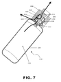
- FIG. 7 illustrates possible leak sources of one embodiment of the integrated fuel supply and fuel supply cleaner system.
- pressurized fuel is allowed to reach the outer o-rings ( 620 , 630 ) through the radial orifices ( 270 ; FIG. 5 ) of the impurity removal cartridge ( 230 ). If the fluid system coupler ( 600 ) does not properly seal around the impurity removal cartridge ( 230 ), pressurized fuel that has passed through the radial orifices ( 270 ; FIG. 5 ) may escape through the second outer o-ring ( 620 ) to the atmosphere. This leakage to the atmosphere may pose a severe fire and/or explosion hazard.
- the radial orifices ( 270 ; FIG. 5 ) are formed prior to the fuel-filtering material ( 240 ) so that any pressurized fuel that is allowed to reach the second outer o-ring ( 620 ) still contains odorizing agents.
- This embodiment of the impurity removal cartridge ( 230 ) allows for the detection of an external fuel leak through scent recognition of a user while still providing deodorized fuel to the system.
- a user may remove both the fuel container ( 210 ) and the impurity removal cartridge ( 230 ) simultaneously as a single unit by de-coupling the fluid system coupler ( 600 ) from the impurity removal cartridge ( 230 ). Both the fuel container ( 210 ) and the impurity removal cartridge may then be replaced with both a new fuel container ( 210 ) and a new impurity removal cartridge ( 230 ).
- This embodiment of the integrated fuel supply allows the change out frequency of the impurity removal cartridge ( 230 ) to be the same as the life of the fuel container ( 210 ) thereby freeing the user from changing out both an in-line sulfur filter and the fuel cartridge at different times.
- odorized fuel may leak past the first outer o-ring ( 630 ) or both of the inner o-rings ( 625 , 635 ) and into the system fuel stream without passing through the fuel-filtering material ( 240 ).
- additional o-rings may be placed on various locations of the system coupler. The inclusion of additional o-rings or other sealing means will reduce the likelihood of odorized fuel leaking past the impurity removal cartridge ( 230 ).
- an in-line removable filter may also be placed within the present system as a safeguard against any odorized fuel that bypasses the impurity removal cartridge ( 230 ) due to one of the above-mentioned leaks.
- any odorizing agent that has leaked past the impurity removal cartridge ( 230 ) will be removed from the fuel prior to reaching the reformer or other system components.
- the inline filter will need to be removed periodically, the incorporation of the impurity removal cartridge ( 230 ) with the fuel container ( 210 ) will greatly reduce the exposure of the inline filter to odorizing agents. As a result, the change out frequency of the inline filter will be greatly reduced.
- the life of the inline filter may be designed to match the product life of the system to which it is incorporated, thereby completely eliminating the need for replacement.
- the present invention in its various embodiments, simultaneously reduces the maintenance needed by a fuel supply while preserving its safety features.
- the present invention provides an apparatus for integrally connecting a fuel supply container to a fuel supply filter.
- a user no longer needs to periodically change an in-line filter. Rather, the integrated filter may be removed and replaced each time a new fuel supply is provided.
- the present invention also allows non-filtered, odorized gas to be present in the system sealing means to provide an odorized source of leak detection.
Landscapes
- Chemical & Material Sciences (AREA)
- Engineering & Computer Science (AREA)
- Chemical Kinetics & Catalysis (AREA)
- Life Sciences & Earth Sciences (AREA)
- General Chemical & Material Sciences (AREA)
- Health & Medical Sciences (AREA)
- Organic Chemistry (AREA)
- Manufacturing & Machinery (AREA)
- Sustainable Development (AREA)
- Sustainable Energy (AREA)
- Electrochemistry (AREA)
- General Health & Medical Sciences (AREA)
- General Engineering & Computer Science (AREA)
- Combustion & Propulsion (AREA)
- Inorganic Chemistry (AREA)
- Mechanical Engineering (AREA)
- Medicinal Chemistry (AREA)
- Oncology (AREA)
- Communicable Diseases (AREA)
- Nuclear Medicine, Radiotherapy & Molecular Imaging (AREA)
- Pharmacology & Pharmacy (AREA)
- Animal Behavior & Ethology (AREA)
- Public Health (AREA)
- Veterinary Medicine (AREA)
- Fuel Cell (AREA)
- Filling Or Discharging Of Gas Storage Vessels (AREA)
- Hydrogen, Water And Hydrids (AREA)
Abstract
Description
Claims (36)
Priority Applications (7)
| Application Number | Priority Date | Filing Date | Title |
|---|---|---|---|
| US10/382,701 US7419060B2 (en) | 2003-03-05 | 2003-03-05 | Integrated fuel container and impurity removal cartridge |
| TW092127303A TWI319638B (en) | 2003-03-05 | 2003-10-02 | Integrated fuel container and impurity removal cartridge |
| DE60307420T DE60307420D1 (en) | 2003-03-05 | 2003-10-09 | Fuel tank with integrated sulfur filter |
| EP03022911A EP1468857B1 (en) | 2003-03-05 | 2003-10-09 | Fuel container with integrated sulfur removal cartridge |
| CA002448677A CA2448677A1 (en) | 2003-03-05 | 2003-11-06 | Integrated fuel container and impurity removal cartridge |
| JP2004050957A JP4080437B2 (en) | 2003-03-05 | 2004-02-26 | Integrated fuel container and impurity removal cartridge |
| KR1020040014630A KR101176641B1 (en) | 2003-03-05 | 2004-03-04 | Integrated fuel container and impurity removal cartridge |
Applications Claiming Priority (1)
| Application Number | Priority Date | Filing Date | Title |
|---|---|---|---|
| US10/382,701 US7419060B2 (en) | 2003-03-05 | 2003-03-05 | Integrated fuel container and impurity removal cartridge |
Publications (2)
| Publication Number | Publication Date |
|---|---|
| US20040175600A1 US20040175600A1 (en) | 2004-09-09 |
| US7419060B2 true US7419060B2 (en) | 2008-09-02 |
Family
ID=32908214
Family Applications (1)
| Application Number | Title | Priority Date | Filing Date |
|---|---|---|---|
| US10/382,701 Active 2024-07-28 US7419060B2 (en) | 2003-03-05 | 2003-03-05 | Integrated fuel container and impurity removal cartridge |
Country Status (7)
| Country | Link |
|---|---|
| US (1) | US7419060B2 (en) |
| EP (1) | EP1468857B1 (en) |
| JP (1) | JP4080437B2 (en) |
| KR (1) | KR101176641B1 (en) |
| CA (1) | CA2448677A1 (en) |
| DE (1) | DE60307420D1 (en) |
| TW (1) | TWI319638B (en) |
Cited By (17)
| Publication number | Priority date | Publication date | Assignee | Title |
|---|---|---|---|---|
| US20090053580A1 (en) * | 2006-10-25 | 2009-02-26 | Canon Kabushiki Kaisha | Inflammable substance sensor and fuel cell including the same |
| US20090258264A1 (en) * | 2008-04-14 | 2009-10-15 | Ballard Gary L | Cartridge adsorber system for removing hydrogen sulfide from reformate |
| USD654562S1 (en) * | 2011-09-15 | 2012-02-21 | Whirlpool Corporation | Filter unit |
| USD654565S1 (en) * | 2011-09-15 | 2012-02-21 | Whirlpool Corporation | Filter unit |
| USD654566S1 (en) * | 2011-09-15 | 2012-02-21 | Whirlpool Corporation | Filter unit |
| USD654561S1 (en) * | 2011-09-15 | 2012-02-21 | Whirlpool Corporation | Filter unit |
| USD654559S1 (en) * | 2011-09-15 | 2012-02-21 | Whirlpool Corporation | Filter unit |
| USD654563S1 (en) * | 2011-09-15 | 2012-02-21 | Whirlpool Corporation | Filter unit |
| USD654560S1 (en) * | 2011-09-15 | 2012-02-21 | Whirlpool Corporation | Filter unit |
| USD654564S1 (en) * | 2011-09-15 | 2012-02-21 | Whirlpool Corporation | Filter unit |
| USD655377S1 (en) * | 2011-09-15 | 2012-03-06 | Whirlpool Corporation | Filter unit |
| USD655378S1 (en) * | 2011-09-15 | 2012-03-06 | Whirlpool Corporation | Filter unit |
| US10109867B2 (en) | 2013-06-26 | 2018-10-23 | Upstart Power, Inc. | Solid oxide fuel cell with flexible fuel rod support structure |
| US10573911B2 (en) | 2015-10-20 | 2020-02-25 | Upstart Power, Inc. | SOFC system formed with multiple thermally conductive pathways |
| US10790523B2 (en) | 2015-10-20 | 2020-09-29 | Upstart Power, Inc. | CPOX reactor control system and method |
| US11108072B2 (en) | 2016-08-11 | 2021-08-31 | Upstart Power, Inc. | Planar solid oxide fuel unit cell and stack |
| US11784331B2 (en) | 2014-10-07 | 2023-10-10 | Upstart Power, Inc. | SOFC-conduction |
Families Citing this family (19)
| Publication number | Priority date | Publication date | Assignee | Title |
|---|---|---|---|---|
| WO2004102717A1 (en) * | 2003-05-16 | 2004-11-25 | Gs Yuasa Corporation | Liquid fuel type fuel cell and fuel for the cell |
| WO2005004258A2 (en) * | 2003-06-27 | 2005-01-13 | Ultracell Corporation | Portable fuel cartridge for fuel cells |
| US7306641B2 (en) | 2003-09-12 | 2007-12-11 | Hewlett-Packard Development Company, L.P. | Integral fuel cartridge and filter |
| US7329348B2 (en) * | 2003-12-01 | 2008-02-12 | Societe Bic | Fuel cell system including an ion filter |
| US7968250B2 (en) | 2004-06-25 | 2011-06-28 | Ultracell Corporation | Fuel cartridge connectivity |
| US7648792B2 (en) | 2004-06-25 | 2010-01-19 | Ultracell Corporation | Disposable component on a fuel cartridge and for use with a portable fuel cell system |
| US20060006108A1 (en) * | 2004-07-08 | 2006-01-12 | Arias Jeffrey L | Fuel cell cartridge and fuel delivery system |
| JP2007066618A (en) * | 2005-08-30 | 2007-03-15 | Toshiba Corp | Fuel cell |
| KR101314982B1 (en) | 2006-01-17 | 2013-10-04 | 삼성에스디아이 주식회사 | fuel cell system using butane |
| WO2008020876A2 (en) * | 2006-01-19 | 2008-02-21 | Direct Methanol Fuel Cell Corporation | Fuel cartridge |
| US20080029156A1 (en) * | 2006-01-19 | 2008-02-07 | Rosal Manuel A D | Fuel cartridge |
| JP5049531B2 (en) * | 2006-08-09 | 2012-10-17 | 本田技研工業株式会社 | Fuel cell |
| KR100776504B1 (en) * | 2006-11-14 | 2007-11-29 | 삼성에스디아이 주식회사 | Fuel cell system |
| US7946430B2 (en) * | 2007-05-15 | 2011-05-24 | Cummins Filtration Ip, Inc. | Filter with protruding member for engaging valve in head |
| EP2218679B1 (en) * | 2007-12-07 | 2017-05-03 | Panasonic Intellectual Property Management Co., Ltd. | Method of controlling a hydrogen generation apparatus and method of controlling a fuel cell system |
| US8349037B2 (en) | 2008-09-01 | 2013-01-08 | Basf Se | Adsorber material and process for desulfurizing hydrocarbonaceous gases |
| US20100273068A1 (en) * | 2009-04-22 | 2010-10-28 | Adaptive Materials, Inc. | Fuel cell system including a fuel filter member with a filter property indicator |
| US20110189587A1 (en) * | 2010-02-01 | 2011-08-04 | Adaptive Materials, Inc. | Interconnect Member for Fuel Cell |
| KR101951439B1 (en) | 2018-08-14 | 2019-05-22 | 아크로랩스 주식회사 | Fuel cell system and method for operating |
Citations (22)
| Publication number | Priority date | Publication date | Assignee | Title |
|---|---|---|---|---|
| US3004670A (en) * | 1958-02-03 | 1961-10-17 | Beam Products Mfg Co | Combined fuel filter and lock-off valve and fuel filter |
| US3250242A (en) * | 1964-03-30 | 1966-05-10 | William L Fisher | Clogged filter indicator device |
| US4112984A (en) * | 1977-07-26 | 1978-09-12 | Gaston Guglia | Capped fuel tank funnel |
| US4522159A (en) * | 1983-04-13 | 1985-06-11 | Michigan Consolidated Gas Co. | Gaseous hydrocarbon fuel storage system and power plant for vehicles and associated refueling apparatus |
| US5354362A (en) * | 1991-02-22 | 1994-10-11 | Sowinski Richard F | Method for filtering odorant from a gas stream |
| JPH08247439A (en) * | 1995-03-09 | 1996-09-27 | Sanyo Electric Co Ltd | Combustion device |
| US5879826A (en) | 1995-07-05 | 1999-03-09 | Humboldt State University Foundation | Proton exchange membrane fuel cell |
| US5928512A (en) * | 1996-04-03 | 1999-07-27 | Plymouth Products, Inc. | Demountable filter for a bottle or the like |
| US5938800A (en) * | 1997-11-13 | 1999-08-17 | Mcdermott Technology, Inc. | Compact multi-fuel steam reformer |
| US6098652A (en) * | 1999-01-21 | 2000-08-08 | Parr Manufacturing, Inc. | Quick connect fuel filter and regulator |
| DE19921816C1 (en) | 1999-05-11 | 2000-10-26 | Andre Peine | Fuel cell system has fuel dell device combined with fuel reservoir and device for receiving waste product in form of filter or ion exchanger |
| US6183895B1 (en) * | 1996-07-02 | 2001-02-06 | Matsushita Electric Works, Ltd. | Fuel-cell power generating system |
| DE10040011A1 (en) | 1999-08-12 | 2001-02-15 | Thomas Hocker | Fuel cell arrangement has a three-way valve directly arranged before the sulfur filter which is arranged before sulfur-sensitive reformer parts in the flow direction of a process gas |
| US6221117B1 (en) | 1996-10-30 | 2001-04-24 | Idatech, Llc | Hydrogen producing fuel processing system |
| US6247486B1 (en) * | 1995-09-28 | 2001-06-19 | Robert Bosch Gmbh | Liquid filter with built-in pressure regulator |
| JP2002083623A (en) * | 2000-06-27 | 2002-03-22 | Idemitsu Kosan Co Ltd | Fuel cell facility, its fuel and fuel supply device |
| US20020090538A1 (en) * | 2000-12-20 | 2002-07-11 | Martin Schaefer | Fuel cell system and method of operating the fuel cell system |
| US6492050B1 (en) | 1997-10-01 | 2002-12-10 | Acumentrics Corporation | Integrated solid oxide fuel cell and reformer |
| US20030113598A1 (en) * | 2001-12-19 | 2003-06-19 | Ballard Power Systems Inc. | Method and apparatus for removing sulfur from a hydrocarbon fuel |
| US20040094488A1 (en) * | 2002-09-06 | 2004-05-20 | Grant Barry S. | Fuel filter with leak avoidance plug |
| US6780534B2 (en) * | 2001-04-11 | 2004-08-24 | Donaldson Company, Inc. | Filter assembly for intake air of fuel cell |
| US6861002B2 (en) * | 2002-04-17 | 2005-03-01 | Watervisions International, Inc. | Reactive compositions for fluid treatment |
Family Cites Families (7)
| Publication number | Priority date | Publication date | Assignee | Title |
|---|---|---|---|---|
| US3954614A (en) * | 1972-07-31 | 1976-05-04 | Glasrock Products, Inc. | Serum skimmer and filter separation unit |
| US4057499A (en) * | 1973-03-09 | 1977-11-08 | Buono Frank S | Apparatus and method for separation of blood |
| US3814258A (en) * | 1973-03-15 | 1974-06-04 | Dickinson And Co | Blood plasma separator with filter |
| US3932277A (en) * | 1974-03-29 | 1976-01-13 | Bio-Logics Products, Inc. | Method and apparatus for separating blood fractions |
| US4210623A (en) * | 1978-05-01 | 1980-07-01 | Owens-Illinois, Inc. | Fluid collection apparatus |
| JPS61258961A (en) | 1985-04-30 | 1986-11-17 | ミシガン・コンソリデ−テツド・ガス・カンパニ− | Hydrocarbon gas fuel storage system and engine system for car |
| US6315934B1 (en) | 1995-05-08 | 2001-11-13 | Shell Oil Company | Process for preparing poly(thimethylene therephthalate) carpet yarn |
-
2003
- 2003-03-05 US US10/382,701 patent/US7419060B2/en active Active
- 2003-10-02 TW TW092127303A patent/TWI319638B/en not_active IP Right Cessation
- 2003-10-09 DE DE60307420T patent/DE60307420D1/en not_active Expired - Lifetime
- 2003-10-09 EP EP03022911A patent/EP1468857B1/en not_active Expired - Fee Related
- 2003-11-06 CA CA002448677A patent/CA2448677A1/en not_active Abandoned
-
2004
- 2004-02-26 JP JP2004050957A patent/JP4080437B2/en not_active Expired - Fee Related
- 2004-03-04 KR KR1020040014630A patent/KR101176641B1/en active IP Right Grant
Patent Citations (22)
| Publication number | Priority date | Publication date | Assignee | Title |
|---|---|---|---|---|
| US3004670A (en) * | 1958-02-03 | 1961-10-17 | Beam Products Mfg Co | Combined fuel filter and lock-off valve and fuel filter |
| US3250242A (en) * | 1964-03-30 | 1966-05-10 | William L Fisher | Clogged filter indicator device |
| US4112984A (en) * | 1977-07-26 | 1978-09-12 | Gaston Guglia | Capped fuel tank funnel |
| US4522159A (en) * | 1983-04-13 | 1985-06-11 | Michigan Consolidated Gas Co. | Gaseous hydrocarbon fuel storage system and power plant for vehicles and associated refueling apparatus |
| US5354362A (en) * | 1991-02-22 | 1994-10-11 | Sowinski Richard F | Method for filtering odorant from a gas stream |
| JPH08247439A (en) * | 1995-03-09 | 1996-09-27 | Sanyo Electric Co Ltd | Combustion device |
| US5879826A (en) | 1995-07-05 | 1999-03-09 | Humboldt State University Foundation | Proton exchange membrane fuel cell |
| US6247486B1 (en) * | 1995-09-28 | 2001-06-19 | Robert Bosch Gmbh | Liquid filter with built-in pressure regulator |
| US5928512A (en) * | 1996-04-03 | 1999-07-27 | Plymouth Products, Inc. | Demountable filter for a bottle or the like |
| US6183895B1 (en) * | 1996-07-02 | 2001-02-06 | Matsushita Electric Works, Ltd. | Fuel-cell power generating system |
| US6221117B1 (en) | 1996-10-30 | 2001-04-24 | Idatech, Llc | Hydrogen producing fuel processing system |
| US6492050B1 (en) | 1997-10-01 | 2002-12-10 | Acumentrics Corporation | Integrated solid oxide fuel cell and reformer |
| US5938800A (en) * | 1997-11-13 | 1999-08-17 | Mcdermott Technology, Inc. | Compact multi-fuel steam reformer |
| US6098652A (en) * | 1999-01-21 | 2000-08-08 | Parr Manufacturing, Inc. | Quick connect fuel filter and regulator |
| DE19921816C1 (en) | 1999-05-11 | 2000-10-26 | Andre Peine | Fuel cell system has fuel dell device combined with fuel reservoir and device for receiving waste product in form of filter or ion exchanger |
| DE10040011A1 (en) | 1999-08-12 | 2001-02-15 | Thomas Hocker | Fuel cell arrangement has a three-way valve directly arranged before the sulfur filter which is arranged before sulfur-sensitive reformer parts in the flow direction of a process gas |
| JP2002083623A (en) * | 2000-06-27 | 2002-03-22 | Idemitsu Kosan Co Ltd | Fuel cell facility, its fuel and fuel supply device |
| US20020090538A1 (en) * | 2000-12-20 | 2002-07-11 | Martin Schaefer | Fuel cell system and method of operating the fuel cell system |
| US6780534B2 (en) * | 2001-04-11 | 2004-08-24 | Donaldson Company, Inc. | Filter assembly for intake air of fuel cell |
| US20030113598A1 (en) * | 2001-12-19 | 2003-06-19 | Ballard Power Systems Inc. | Method and apparatus for removing sulfur from a hydrocarbon fuel |
| US6861002B2 (en) * | 2002-04-17 | 2005-03-01 | Watervisions International, Inc. | Reactive compositions for fluid treatment |
| US20040094488A1 (en) * | 2002-09-06 | 2004-05-20 | Grant Barry S. | Fuel filter with leak avoidance plug |
Non-Patent Citations (2)
| Title |
|---|
| English abstract of JP 2002-83623 A. * |
| English abstract of JP 8-247439. * |
Cited By (20)
| Publication number | Priority date | Publication date | Assignee | Title |
|---|---|---|---|---|
| US20090053580A1 (en) * | 2006-10-25 | 2009-02-26 | Canon Kabushiki Kaisha | Inflammable substance sensor and fuel cell including the same |
| US20090258264A1 (en) * | 2008-04-14 | 2009-10-15 | Ballard Gary L | Cartridge adsorber system for removing hydrogen sulfide from reformate |
| US7896952B2 (en) * | 2008-04-14 | 2011-03-01 | Delphi Technologies, Inc. | Cartridge adsorber system for removing hydrogen sulfide from reformate |
| USD654564S1 (en) * | 2011-09-15 | 2012-02-21 | Whirlpool Corporation | Filter unit |
| USD655378S1 (en) * | 2011-09-15 | 2012-03-06 | Whirlpool Corporation | Filter unit |
| USD654566S1 (en) * | 2011-09-15 | 2012-02-21 | Whirlpool Corporation | Filter unit |
| USD654561S1 (en) * | 2011-09-15 | 2012-02-21 | Whirlpool Corporation | Filter unit |
| USD654559S1 (en) * | 2011-09-15 | 2012-02-21 | Whirlpool Corporation | Filter unit |
| USD654563S1 (en) * | 2011-09-15 | 2012-02-21 | Whirlpool Corporation | Filter unit |
| USD654560S1 (en) * | 2011-09-15 | 2012-02-21 | Whirlpool Corporation | Filter unit |
| USD654562S1 (en) * | 2011-09-15 | 2012-02-21 | Whirlpool Corporation | Filter unit |
| USD655377S1 (en) * | 2011-09-15 | 2012-03-06 | Whirlpool Corporation | Filter unit |
| USD654565S1 (en) * | 2011-09-15 | 2012-02-21 | Whirlpool Corporation | Filter unit |
| US10109867B2 (en) | 2013-06-26 | 2018-10-23 | Upstart Power, Inc. | Solid oxide fuel cell with flexible fuel rod support structure |
| US11784331B2 (en) | 2014-10-07 | 2023-10-10 | Upstart Power, Inc. | SOFC-conduction |
| US10573911B2 (en) | 2015-10-20 | 2020-02-25 | Upstart Power, Inc. | SOFC system formed with multiple thermally conductive pathways |
| US10790523B2 (en) | 2015-10-20 | 2020-09-29 | Upstart Power, Inc. | CPOX reactor control system and method |
| US11605825B2 (en) | 2015-10-20 | 2023-03-14 | Upstart Power, Inc. | CPOX reactor control system and method |
| US11108072B2 (en) | 2016-08-11 | 2021-08-31 | Upstart Power, Inc. | Planar solid oxide fuel unit cell and stack |
| US11664517B2 (en) | 2016-08-11 | 2023-05-30 | Upstart Power, Inc. | Planar solid oxide fuel unit cell and stack |
Also Published As
| Publication number | Publication date |
|---|---|
| JP4080437B2 (en) | 2008-04-23 |
| EP1468857A3 (en) | 2004-10-27 |
| CA2448677A1 (en) | 2004-09-05 |
| KR101176641B1 (en) | 2012-08-23 |
| DE60307420D1 (en) | 2006-09-21 |
| JP2004308893A (en) | 2004-11-04 |
| TWI319638B (en) | 2010-01-11 |
| TW200418225A (en) | 2004-09-16 |
| US20040175600A1 (en) | 2004-09-09 |
| KR20040078887A (en) | 2004-09-13 |
| EP1468857A2 (en) | 2004-10-20 |
| EP1468857B1 (en) | 2006-08-09 |
Similar Documents
| Publication | Publication Date | Title |
|---|---|---|
| US7419060B2 (en) | Integrated fuel container and impurity removal cartridge | |
| US8283079B2 (en) | Fuel cell power generator with water reservoir | |
| US20120315557A1 (en) | Oxygen removal systems during fuel cell shutdown | |
| JP5410411B2 (en) | Desulfurizer, hydrogen generator, fuel cell power generation system, and desulfurizing agent cartridge | |
| JP2006278120A (en) | Fuel cell power generating system, method for preparing its starting, and method for maintaining system | |
| WO2003099421A1 (en) | Gas purification system | |
| US7611793B2 (en) | Fuel cell system, hydrogen gas supply unit, and method of controlling fuel cell system | |
| US20040237488A1 (en) | Filter assembly with spin-on filters, and methods | |
| US7122258B2 (en) | Fuel cell air system and method | |
| KR20210022167A (en) | Nitrogen gas generator for preventing fire of energy storage system | |
| WO2002015315A1 (en) | Fuel cell system | |
| US20040072050A1 (en) | Fuel cell system | |
| US20160169068A1 (en) | Turbine bearing lubricant filtration system | |
| US7896952B2 (en) | Cartridge adsorber system for removing hydrogen sulfide from reformate | |
| US20210057769A1 (en) | Desulfurizer | |
| KR101421650B1 (en) | Desulfurizer room temperature fuel cells | |
| JP4929568B2 (en) | Fuel cell drive device | |
| JP2007193952A (en) | Fuel cell | |
| JP2010170963A (en) | Fuel cell system | |
| JP2005327650A (en) | Fuel cell system and hydrogen gas supply device | |
| JP2018188556A (en) | LPG supply system | |
| JP5912878B2 (en) | Hydrogen oxygen generator and operation method of hydrogen oxygen generator | |
| JP2004319276A (en) | Hydrogen supply device and hydrogen supply method of fuel cell | |
| JP2001043873A (en) | Fuel-cell power generating plant | |
| CN110026052A (en) | Hydrogen energy source fuel cell chemical filter |
Legal Events
| Date | Code | Title | Description |
|---|---|---|---|
| AS | Assignment |
Owner name: HEWLETT-PACKARD COMPANY, COLORADO Free format text: ASSIGNMENT OF ASSIGNORS INTEREST;ASSIGNORS:ARTHUR, ALAN R.;HARDING, PHILIP H.;REEL/FRAME:013963/0158;SIGNING DATES FROM 20030228 TO 20030303 |
|
| STCF | Information on status: patent grant |
Free format text: PATENTED CASE |
|
| CC | Certificate of correction | ||
| AS | Assignment |
Owner name: EVEREADY BATTERY COMPANY, INC., MISSOURI Free format text: ASSIGNMENT OF ASSIGNORS INTEREST;ASSIGNORS:HEWLETT-PACKARD DEVELOPMENT COMPANY, L.P.;HEWLETT-PACKARD COMPANY;REEL/FRAME:026463/0542 Effective date: 20101029 |
|
| FPAY | Fee payment |
Year of fee payment: 4 |
|
| AS | Assignment |
Owner name: INTELLIGENT ENERGY LIMITED, UNITED KINGDOM Free format text: ASSIGNMENT OF ASSIGNORS INTEREST;ASSIGNOR:EVEREADY BATTERY COMPANY, INC.;REEL/FRAME:032124/0514 Effective date: 20131219 |
|
| FPAY | Fee payment |
Year of fee payment: 8 |
|
| FEPP | Fee payment procedure |
Free format text: 11.5 YR SURCHARGE- LATE PMT W/IN 6 MO, LARGE ENTITY (ORIGINAL EVENT CODE: M1556); ENTITY STATUS OF PATENT OWNER: LARGE ENTITY |
|
| MAFP | Maintenance fee payment |
Free format text: PAYMENT OF MAINTENANCE FEE, 12TH YEAR, LARGE ENTITY (ORIGINAL EVENT CODE: M1553); ENTITY STATUS OF PATENT OWNER: LARGE ENTITY Year of fee payment: 12 |