US7379570B2 - Optical engine for fingerprint reader - Google Patents
Optical engine for fingerprint reader Download PDFInfo
- Publication number
- US7379570B2 US7379570B2 US11/037,205 US3720505A US7379570B2 US 7379570 B2 US7379570 B2 US 7379570B2 US 3720505 A US3720505 A US 3720505A US 7379570 B2 US7379570 B2 US 7379570B2
- Authority
- US
- United States
- Prior art keywords
- optical
- optical surface
- prism
- total
- lens
- Prior art date
- Legal status (The legal status is an assumption and is not a legal conclusion. Google has not performed a legal analysis and makes no representation as to the accuracy of the status listed.)
- Expired - Fee Related, expires
Links
Images


Classifications
-
- G—PHYSICS
- G06—COMPUTING; CALCULATING OR COUNTING
- G06V—IMAGE OR VIDEO RECOGNITION OR UNDERSTANDING
- G06V40/00—Recognition of biometric, human-related or animal-related patterns in image or video data
- G06V40/10—Human or animal bodies, e.g. vehicle occupants or pedestrians; Body parts, e.g. hands
- G06V40/12—Fingerprints or palmprints
- G06V40/13—Sensors therefor
- G06V40/1324—Sensors therefor by using geometrical optics, e.g. using prisms
Definitions
- the present invention relates to an optical engine for fingerprint reader, especially an integrated optical prism with double functions of prism and lens for replacing optical engines of traditional fingerprint readers that consists of a right-angle prism and a lens.
- the present invention simplifies the assembling of components and increases the stability and reliability of the optical engine.
- a traditional optical engine 10 is composed by a right-angle prism 11 and a lens 12 .
- the position for finger F 13 is on the inclined optical surface of the right-angle prism 11 while a LED (light emitting diode) light source 14 is disposed on one of the optical surfaces 15 of the right-angle prism 11 (such as horizontal plane shown in figure).
- the optical engine 10 with two-piece structure has following disadvantages:
- the present invention avoids the shortcomings of conventional two-piece engine and has simplified assembling way. Thus inaccuracy during processing is reduced, and the stability and reliability of the optical engine is improved.
- the angle for the position for putting finger is 130 degrees (the angle in conventional right-angle prism is 90 degrees).
- the image of fingerprint goes through two times of total internal reflection and then enters the lens of the optical prism. There is a complete light path between the fingerprint and the sensing device thus the signal to noise ratio (S/N) is increased.
- FIG. 1 is a schematic drawing showing side view of a traditional optical fingerprint reader
- FIG. 2 is a schematic drawing showing side view of the present invention
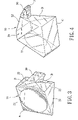
- FIG. 3 is a perspective view of an optical prism in accordance with the present invention.
- FIG. 4 is a perspective view of the embodiment in FIG. 3 from another angle;
- FIG. 5 is a schematic drawing of light path in an optical engine in accordance with the present invention.
- FIG. 6 is a schematic drawing of the lens in accordance with the present invention (with reference size);
- FIGS. 7A , 7 B, 7 C are schematic drawing of the three surfaces (with reference size) of an optical prism in accordance with the present invention.
- an optical engine in accordance with the present invention includes a prism 20 , a lens 30 , and a sensing device 40 .
- the present invention features on that: the prism 20 and the lens 30 are integrated into one piece of an optical prism 50 so that the optical prism 50 has the total internal reflection of the prism 20 as well as the image displaying function of the lens 30 , as shown in FIG. 1 .
- the one-piece optical prism 50 includes the prism 20 and the lens 30 .
- the prism 20 is a prism with light path moving to and fro and having an optical surface A for being pressed by a finger F, an optical surface B facing a LED light source, a first total-reflective optical surface C and a second total-reflective optical surface D, four optical surfaces.
- the angle between the optical surface B and the first total-reflective optical surface C is about 130°, replacing conventional 90 degrees angle of the right angle prism 11 shown in FIG. 1 .
- the angle facing upwards between the optical surface A and the optical surface B is an acute angle (less than 90 degrees) so as to form the second total-reflective optical surface D with smaller width.
- the lens 30 is disposed on the position extended from the second total-reflective optical surface D and the optical surface B and a non-sphere 31 is on the tail part of the lens 30 , as shown in FIG. 6 .
- the non-sphere 31 faces a receiving plane 41 of a sensing device 40 .
- the sensing device 40 is a device for receiving and processing images such as CMOS or CCD.
- the image of fingerprint passes the first total-reflective optical surface C and the second total-reflective optical surface D, after two times of total reflection, thought the lens 30 forms an image.
- the signal to noise ratio (S/N) is increased effectively.
- an arched concave 21 with diameter of 120 mm is formed with ergonomically design and more clear image of fingerprint.
- an embodiment of the optical prism 50 in accordance with the present invention is disclosed. Due to one-piece design of the optical prism 50 , the optical engine of the fingerprint reader according to the present invention is with light-weight and compact design. For example, the size of an embodiment is under 14.5 mm (H) ⁇ 44 mm (L) ⁇ 26 mm (W) for the convenience of being modularized. Thus it is easy to be assembled on various products that include an USB socket thereof. Secondly, each one of several surfaces on the optical prism 50 can be a locating surface for easy assembling. And the one-piece optical prism 50 provides a complete optical path thus can be used in combination with CMOS sensing device 40 so as to form a reliable optical engine module with excellent quality.
- TIR Total Internal Reflection
- the function of Total Internal Reflection (TIR) of the first total-reflective optical surface C and the second total-reflective optical surface D can also be achieved by design of various material or angles between optical surfaces of the optical prism 50 .
- a layer of reflective membrane (such as aluminum) is directly plated on the first total-reflective optical surface C and the second total-reflective optical surface D so as to make the optical prism 50 have the Total Internal Reflection function.
- the LED light source is arranged either outside the optical surface B or arranged on other surface of the optical prism 50 , such as prism surfaces 22 , 23 shown in FIG. 3 & FIG. 4 so as to achieve best lighting efficiency.
Abstract
Description
-
- (1) The structure of assembling of two components has larger volume, thus is difficult to get popular support.
- (2) In the two-component structure, the right-
angle prism 11 and thelens 12 shall be localized precisely so as to make the light path straight. Not only the number of components causes the problem, but the difficulty of assembling is also increased. Thus the cost is high. - (3) The
prism 11 is a right angle prism so that an image of theLED light source 14 also forms on thesensing device 17. This leads to the low S/N ratio that has bad effect on efficiency of the device. - (4) The position for putting
finger F 13 is a flat plane so that users need to press in order to get the clear fingerprint image. This causes a bit inconvenience.
Claims (6)
Priority Applications (1)
| Application Number | Priority Date | Filing Date | Title |
|---|---|---|---|
| US11/037,205 US7379570B2 (en) | 2005-01-19 | 2005-01-19 | Optical engine for fingerprint reader |
Applications Claiming Priority (1)
| Application Number | Priority Date | Filing Date | Title |
|---|---|---|---|
| US11/037,205 US7379570B2 (en) | 2005-01-19 | 2005-01-19 | Optical engine for fingerprint reader |
Publications (2)
| Publication Number | Publication Date |
|---|---|
| US20060159317A1 US20060159317A1 (en) | 2006-07-20 |
| US7379570B2 true US7379570B2 (en) | 2008-05-27 |
Family
ID=36683929
Family Applications (1)
| Application Number | Title | Priority Date | Filing Date |
|---|---|---|---|
| US11/037,205 Expired - Fee Related US7379570B2 (en) | 2005-01-19 | 2005-01-19 | Optical engine for fingerprint reader |
Country Status (1)
| Country | Link |
|---|---|
| US (1) | US7379570B2 (en) |
Cited By (5)
| Publication number | Priority date | Publication date | Assignee | Title |
|---|---|---|---|---|
| US20110018681A1 (en) * | 2008-04-01 | 2011-01-27 | Micro Motion, Inc. | method, computer program product, and system for preventing inadvertent configuration of electronic devices provided with infrared data association interfaces |
| EP3142043A1 (en) | 2015-09-11 | 2017-03-15 | Jenetric GmbH | Device and method for optical recording of areas of skin with blood flowing through |
| DE102015116026A1 (en) | 2015-09-22 | 2017-03-23 | JENETRIC GmbH | Device and method for direct optical image acquisition of documents and / or living skin areas without imaging optical elements |
| DE102016114188A1 (en) | 2016-08-01 | 2018-02-01 | JENETRIC GmbH | Device and method for direct recording of prints of unrolled fingers |
| US9892306B2 (en) | 2015-09-14 | 2018-02-13 | JENETRIC GmbH | Device and method for the direct optical recording of live skin areas |
Families Citing this family (11)
| Publication number | Priority date | Publication date | Assignee | Title |
|---|---|---|---|---|
| US7379570B2 (en) * | 2005-01-19 | 2008-05-27 | E-Pin International Tech Co., Ltd. | Optical engine for fingerprint reader |
| KR100879381B1 (en) * | 2007-06-04 | 2009-01-20 | 테스텍 주식회사 | Optical fingerprint acquisition apparatus using a prism |
| CN102238899A (en) * | 2008-10-03 | 2011-11-09 | 皇家飞利浦电子股份有限公司 | Device for optically examining the interior of a turbid medium |
| JP5079675B2 (en) * | 2008-12-08 | 2012-11-21 | 日立マクセル株式会社 | Biometric information acquisition device, biometric authentication device, light guide, and image acquisition device |
| KR101068397B1 (en) * | 2010-01-22 | 2011-09-28 | 주식회사 슈프리마 | Optical fingerprint input device capable of detecting fake fingerprints |
| US20120121143A1 (en) * | 2010-11-11 | 2012-05-17 | Hung-Te Lee | Fingerprint imaging system |
| US9886618B2 (en) * | 2011-03-25 | 2018-02-06 | Nec Corporation | Authentication apparatus and authentication method |
| EP2710582A4 (en) * | 2011-05-17 | 2014-12-31 | Cross Match Technologies Inc | Fingerprint sensors |
| JP6257252B2 (en) | 2012-10-04 | 2018-01-10 | アイビー コリア リミテッドIB Korea Ltd. | Anti-shock reading of raised pattern |
| US9228824B2 (en) | 2013-05-10 | 2016-01-05 | Ib Korea Ltd. | Combined sensor arrays for relief print imaging |
| CN106462285B (en) | 2014-04-10 | 2020-06-09 | Ib韩国有限责任公司 | Biometric sensor for touch device |
Citations (17)
| Publication number | Priority date | Publication date | Assignee | Title |
|---|---|---|---|---|
| US3716301A (en) * | 1971-03-17 | 1973-02-13 | Sperry Rand Corp | Fingerprint identification apparatus |
| US4120585A (en) * | 1976-11-19 | 1978-10-17 | Calspan Corporation | Fingerprint identification system using a pliable optical prism |
| US4924085A (en) * | 1988-06-23 | 1990-05-08 | Fujitsu Limited | Uneven-surface data detection apparatus |
| US4925300A (en) * | 1988-08-02 | 1990-05-15 | Rachlin Daniel J | Optical fingerprint imaging device |
| US5625448A (en) * | 1995-03-16 | 1997-04-29 | Printrak International, Inc. | Fingerprint imaging |
| US5650842A (en) * | 1995-10-27 | 1997-07-22 | Identix Incorporated | Device and method for obtaining a plain image of multiple fingerprints |
| US6069969A (en) * | 1994-09-16 | 2000-05-30 | Identicator Technology | Apparatus and method for electronically acquiring fingerprint images |
| US6127674A (en) * | 1997-09-01 | 2000-10-03 | Fujitsu Limited | Uneven-surface data detection apparatus |
| US6154285A (en) * | 1998-12-21 | 2000-11-28 | Secugen Corporation | Surface treatment for optical image capturing system |
| US6750955B1 (en) * | 2002-03-14 | 2004-06-15 | Ic Media Corporation | Compact optical fingerprint sensor and method |
| US20050205667A1 (en) * | 2003-04-04 | 2005-09-22 | Lumidigm, Inc. | Combined total-internal-reflectance and tissue imaging systems and methods |
| US6954261B2 (en) * | 2003-06-17 | 2005-10-11 | Cross Match Technologies, Inc. | System and method for illuminating a platen in a live scanner and producing high-contrast print images |
| US6956608B1 (en) * | 2000-08-11 | 2005-10-18 | Identix Incorporated | Fingerprint imaging device including an optical plate having microreflectors |
| US20060110015A1 (en) * | 2003-04-04 | 2006-05-25 | Lumidigm, Inc. | Systems and methods for improved biometric feature definition |
| US20060159317A1 (en) * | 2005-01-19 | 2006-07-20 | E-Pin International Tech Co., Ltd. | Optical engine for fingerprint reader |
| US7148466B2 (en) * | 2002-12-23 | 2006-12-12 | Identix Incorporated | Apparatus and method for illumination of an optical platen |
| US7212279B1 (en) * | 2002-05-20 | 2007-05-01 | Magna Chip Semiconductor Ltd. | Biometric identity verifiers and methods |
-
2005
- 2005-01-19 US US11/037,205 patent/US7379570B2/en not_active Expired - Fee Related
Patent Citations (19)
| Publication number | Priority date | Publication date | Assignee | Title |
|---|---|---|---|---|
| US3716301A (en) * | 1971-03-17 | 1973-02-13 | Sperry Rand Corp | Fingerprint identification apparatus |
| US4120585A (en) * | 1976-11-19 | 1978-10-17 | Calspan Corporation | Fingerprint identification system using a pliable optical prism |
| US4924085A (en) * | 1988-06-23 | 1990-05-08 | Fujitsu Limited | Uneven-surface data detection apparatus |
| US4925300A (en) * | 1988-08-02 | 1990-05-15 | Rachlin Daniel J | Optical fingerprint imaging device |
| US6069969A (en) * | 1994-09-16 | 2000-05-30 | Identicator Technology | Apparatus and method for electronically acquiring fingerprint images |
| US5625448A (en) * | 1995-03-16 | 1997-04-29 | Printrak International, Inc. | Fingerprint imaging |
| US5650842A (en) * | 1995-10-27 | 1997-07-22 | Identix Incorporated | Device and method for obtaining a plain image of multiple fingerprints |
| US6127674A (en) * | 1997-09-01 | 2000-10-03 | Fujitsu Limited | Uneven-surface data detection apparatus |
| US6154285A (en) * | 1998-12-21 | 2000-11-28 | Secugen Corporation | Surface treatment for optical image capturing system |
| US6956608B1 (en) * | 2000-08-11 | 2005-10-18 | Identix Incorporated | Fingerprint imaging device including an optical plate having microreflectors |
| US6750955B1 (en) * | 2002-03-14 | 2004-06-15 | Ic Media Corporation | Compact optical fingerprint sensor and method |
| US7212279B1 (en) * | 2002-05-20 | 2007-05-01 | Magna Chip Semiconductor Ltd. | Biometric identity verifiers and methods |
| US7148466B2 (en) * | 2002-12-23 | 2006-12-12 | Identix Incorporated | Apparatus and method for illumination of an optical platen |
| US20050205667A1 (en) * | 2003-04-04 | 2005-09-22 | Lumidigm, Inc. | Combined total-internal-reflectance and tissue imaging systems and methods |
| US20060110015A1 (en) * | 2003-04-04 | 2006-05-25 | Lumidigm, Inc. | Systems and methods for improved biometric feature definition |
| US6954261B2 (en) * | 2003-06-17 | 2005-10-11 | Cross Match Technologies, Inc. | System and method for illuminating a platen in a live scanner and producing high-contrast print images |
| US20060028635A1 (en) * | 2003-06-17 | 2006-02-09 | Cross Match Technologies, Inc. | System and method for illuminating a platen in a live scanner and producing high-contrast print images |
| US7119890B2 (en) * | 2003-06-17 | 2006-10-10 | Cross Match Technologies, Inc. | System and method for illuminating a platen in a live scanner and producing high-contrast print images |
| US20060159317A1 (en) * | 2005-01-19 | 2006-07-20 | E-Pin International Tech Co., Ltd. | Optical engine for fingerprint reader |
Cited By (12)
| Publication number | Priority date | Publication date | Assignee | Title |
|---|---|---|---|---|
| US20110018681A1 (en) * | 2008-04-01 | 2011-01-27 | Micro Motion, Inc. | method, computer program product, and system for preventing inadvertent configuration of electronic devices provided with infrared data association interfaces |
| US9000886B2 (en) * | 2008-04-01 | 2015-04-07 | Micro Motion, Inc. | Method, computer program product, and system for preventing inadvertent configuration of electronic devices provided with infrared data association interfaces |
| EP3142043A1 (en) | 2015-09-11 | 2017-03-15 | Jenetric GmbH | Device and method for optical recording of areas of skin with blood flowing through |
| DE102015115381A1 (en) | 2015-09-11 | 2017-03-16 | JENETRIC GmbH | Device and method for the optical recording of impressions of perfused skin areas |
| US10296775B2 (en) | 2015-09-11 | 2019-05-21 | JENETRIC GmbH | Device and method for optical imaging of prints of skin parts with blood circulation |
| US9892306B2 (en) | 2015-09-14 | 2018-02-13 | JENETRIC GmbH | Device and method for the direct optical recording of live skin areas |
| US10607056B2 (en) | 2015-09-14 | 2020-03-31 | JENETRIC GmbH | Device and method for the direct optical recording of live skin areas |
| DE102015116026A1 (en) | 2015-09-22 | 2017-03-23 | JENETRIC GmbH | Device and method for direct optical image acquisition of documents and / or living skin areas without imaging optical elements |
| EP3147823A2 (en) | 2015-09-22 | 2017-03-29 | Jenetric GmbH | Device and method for direct optical recording of documents and/or living areas of skin without imaging optical elements |
| US10116886B2 (en) | 2015-09-22 | 2018-10-30 | JENETRIC GmbH | Device and method for direct optical image capture of documents and/or live skin areas without optical imaging elements |
| DE102016114188A1 (en) | 2016-08-01 | 2018-02-01 | JENETRIC GmbH | Device and method for direct recording of prints of unrolled fingers |
| US10339357B2 (en) | 2016-08-01 | 2019-07-02 | JENETRIC GmbH | Device and method for the direct recording of prints of rolled fingers |
Also Published As
| Publication number | Publication date |
|---|---|
| US20060159317A1 (en) | 2006-07-20 |
Similar Documents
| Publication | Publication Date | Title |
|---|---|---|
| US7379570B2 (en) | Optical engine for fingerprint reader | |
| US6188781B1 (en) | Method and apparatus for illuminating a fingerprint through side illumination of a platen | |
| US20100172552A1 (en) | Fingerprint indentifying system | |
| US8028913B2 (en) | Arrangement for and method of uniformly illuminating direct part markings to be imaged and electro-optically read | |
| US20100208954A1 (en) | Fingerprint identifying system | |
| US20100183200A1 (en) | Fingerprint Input Module | |
| TWI490526B (en) | Optical sensing module and electronical apparatus having the same | |
| US20070188457A1 (en) | Optical mouse system with illumination guide having a light spreading lens | |
| JP2005049367A (en) | Fresnel lens and lighting device | |
| TWM470454U (en) | Contact image sensor device | |
| TW201727536A (en) | Reflective fingerprint identification system | |
| CN100409047C (en) | Light guide and image reader | |
| CN106067014B (en) | Uniform illumination finger surface collecting structure | |
| CN102360425A (en) | Thinned optical fingerprint acquirer | |
| US6276606B1 (en) | Full range bar code scanner | |
| US20070024600A1 (en) | Pen-type optical mouse | |
| EP3343429B1 (en) | Illuminator for dpm scanner | |
| US7173235B2 (en) | Apparatus for optically reading target | |
| US20040028262A1 (en) | Optical system of fingerprint image capture apparatus | |
| US7796489B2 (en) | Optical head with diffuser structure | |
| JP2000307807A (en) | Linear light source unit | |
| TWI547850B (en) | Optical detecting device capable of increasing signal-to-noise ratio and economizing power consumption | |
| CN101408927B (en) | Optical reading head with diffuseness structure | |
| US9922233B1 (en) | Thin type optical fingerprint sensor | |
| JP4915321B2 (en) | Optical information reader |
Legal Events
| Date | Code | Title | Description |
|---|---|---|---|
| AS | Assignment |
Owner name: E-PIN INTERNATIONAL TECH CO., LTD., TAIWAN Free format text: ASSIGNMENT OF ASSIGNORS INTEREST;ASSIGNORS:SHYU, SAN-WUEI;HUA, TING-KUO;REEL/FRAME:016637/0391 Effective date: 20050727 |
|
| FPAY | Fee payment |
Year of fee payment: 4 |
|
| AS | Assignment |
Owner name: LAN-YANG INVESTMENT CO., LTD., TAIWAN Free format text: ASSIGNMENT OF ASSIGNORS INTEREST;ASSIGNOR:E-PIN INTERNATIONAL TECH CO., LTD.;REEL/FRAME:029038/0602 Effective date: 20120919 |
|
| FEPP | Fee payment procedure |
Free format text: PAT HOLDER NO LONGER CLAIMS SMALL ENTITY STATUS, ENTITY STATUS SET TO UNDISCOUNTED (ORIGINAL EVENT CODE: STOL); ENTITY STATUS OF PATENT OWNER: LARGE ENTITY |
|
| AS | Assignment |
Owner name: SILITECH TECHNOLOGY CORPORATION, TAIWAN Free format text: ASSIGNMENT OF ASSIGNORS INTEREST;ASSIGNOR:LAN-YANG INVESTMENT CO., LTD.;REEL/FRAME:030307/0126 Effective date: 20130312 |
|
| AS | Assignment |
Owner name: SILITECH TECHNOLOGY CORPORATION, TAIWAN Free format text: ASSIGNMENT OF ASSIGNORS INTEREST;ASSIGNOR:LAN-YANG INVESTMENT CO., LTD.;REEL/FRAME:030317/0047 Effective date: 20130312 |
|
| REMI | Maintenance fee reminder mailed | ||
| LAPS | Lapse for failure to pay maintenance fees | ||
| STCH | Information on status: patent discontinuation |
Free format text: PATENT EXPIRED DUE TO NONPAYMENT OF MAINTENANCE FEES UNDER 37 CFR 1.362 |
|
| FP | Lapsed due to failure to pay maintenance fee |
Effective date: 20160527 |