US7327576B2 - Heat dissipation device - Google Patents
Heat dissipation device Download PDFInfo
- Publication number
- US7327576B2 US7327576B2 US11/166,311 US16631105A US7327576B2 US 7327576 B2 US7327576 B2 US 7327576B2 US 16631105 A US16631105 A US 16631105A US 7327576 B2 US7327576 B2 US 7327576B2
- Authority
- US
- United States
- Prior art keywords
- heat dissipation
- heat
- base plate
- unit
- units
- Prior art date
- Legal status (The legal status is an assumption and is not a legal conclusion. Google has not performed a legal analysis and makes no representation as to the accuracy of the status listed.)
- Expired - Fee Related, expires
Links
Images


Classifications
-
- G—PHYSICS
- G06—COMPUTING; CALCULATING OR COUNTING
- G06F—ELECTRIC DIGITAL DATA PROCESSING
- G06F1/00—Details not covered by groups G06F3/00 - G06F13/00 and G06F21/00
- G06F1/16—Constructional details or arrangements
- G06F1/20—Cooling means
-
- F—MECHANICAL ENGINEERING; LIGHTING; HEATING; WEAPONS; BLASTING
- F28—HEAT EXCHANGE IN GENERAL
- F28D—HEAT-EXCHANGE APPARATUS, NOT PROVIDED FOR IN ANOTHER SUBCLASS, IN WHICH THE HEAT-EXCHANGE MEDIA DO NOT COME INTO DIRECT CONTACT
- F28D15/00—Heat-exchange apparatus with the intermediate heat-transfer medium in closed tubes passing into or through the conduit walls ; Heat-exchange apparatus employing intermediate heat-transfer medium or bodies
- F28D15/02—Heat-exchange apparatus with the intermediate heat-transfer medium in closed tubes passing into or through the conduit walls ; Heat-exchange apparatus employing intermediate heat-transfer medium or bodies in which the medium condenses and evaporates, e.g. heat pipes
- F28D15/0275—Arrangements for coupling heat-pipes together or with other structures, e.g. with base blocks; Heat pipe cores
Definitions
- the present invention relates to a heat dissipation device, and more particularly to a heat dissipation device suitable for removing heat from chips mounted on add-on cards, such as VGA cards, sound cards or network cards.
- a central processing unit is a core of a computer.
- the CPU generates a great quantity of heat during operation and needs to be cooled to keep the CPU working normally.
- VGA VGA card which processes video information transmitted from the CPU in its own chip and transmits the processed information to a monitor to allow a user to view texts or graphics
- sound card which can enable a computer to manipulate and output sounds or to record sound input from a microphone connected to the computer
- network card which may be inserted into a computer so the computer can be connected to a network.
- These cards also generate heat during operation and need to be cooled, especially for high-level VGA cards which are designed to enable intensive graphics processing or 3-dimension gaming and take part of the task charged to the CPU. Thus, heat dissipation devices are required to remove heat which is generated during operation of these cards. If the heat is not timely removed, it may adversely affect the performance of the cards.
- a card may be cooled by attaching a heat sink on the heat-generating chip of the card.
- the heat sink is more bulk; the heat dissipation efficiency is greater.
- it is impractical to install a bulk heat sink because the space between cards is usually limited.
- a heat dissipation device which is suitable to be installed to an add-on card, such as a VGA card, a sound card, or a network card to remove heat therefrom.
- a heat dissipation device for cooling an add-on card in accordance with a preferred embodiment of the present invention comprises first and second heat dissipation units and at least one heat pipe.
- the heat dissipation units each include a base plate and a fin plate engaged with the base plate.
- the at least one heat pipe includes an evaporating segment received between the base plate and the fin plate of the first heat dissipation unit, and a condensing segment received between the base plate and the fin plate of the second heat dissipation unit, whereby the first and second heat dissipation units are connected by the heat pipe.
- the evaporating segment and the condensing segment of the at least one heat pipe are movably received in the heat dissipation units respectively before the heat dissipation device is installed to the add-on card, and are secured in position and thermally connected with the heat dissipation units respectively after the heat dissipation device is installed securely to the add-on card.
- FIG. 1 is an assembled, isometric view of a heat dissipation device in accordance with a preferred embodiment of the present invention.
- FIG. 2 is an exploded view of FIG. 1 ;
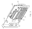
- FIG. 3 is an assembled, isometric view of the heat dissipation device of FIG. 1 , being mounted onto an add-on card to remove heat from a chip thereof;
- FIG. 4 and FIG. 5 are side views showing the process of installing the heat dissipation device to the add-on card.
- FIG. 6 is an isometric view of the add-on card.
- a heat dissipation device of a preferred embodiment of the invention comprises a first heat dissipation unit 10 , a second heat dissipation unit 20 and a pair of heat pipes 30 thermally connecting the first and second heat dissipation units 10 , 20 .
- the heat dissipation device is used to remove heat from a chip 42 mounted onto an add-on card 40 , such as a VGA card (best see in FIG. 6 ).
- the card 40 defines a pair of spaced orifices 46 therein adjacent to the chip 42 .
- the first heat dissipation unit 10 comprises a base plate 12 and a fin plate 14 securable to the base plate 12 .
- the base plate 12 is used for engaging with the chip 42 so that heat generated by the chip 42 is first absorbed by the base plate 12 .
- the base plate 12 comprises a finned portion (not labeled) having a plurality of fins 120 projecting perpendicularly therefrom, for facilitating heat dissipation.
- the base plate 12 further comprises an un-finned portion (not labeled) in which a pair of first grooves 122 , two bores 124 and four screw holes 126 are defined.
- the four screw holes 126 are arranged generally at four corners of the un-finned portion of the base plate 12 .
- the first grooves 122 are parallel to each other and disposed between the screw holes 126 .
- the bores 124 are positioned corresponding to the orifices 46 of the card 40 .
- a pair of pins, such as bolts 16 is used to extend through the bores 124 of the base plate 12 and the orifices 46 of the card 40 .
- the base plate 12 is formed by extrusion to integrally form the finned and un-finned portions (not labeled).
- the fin plate 14 is attached onto the un-finned portion (not labeled) of the base plate 12 to be juxtaposed with the fins 120 of the base plate 12 .
- the fin plate 14 comprises a plurality of fins 140 extending perpendicularly therefrom, and defines a pair of parallel second grooves 142 in a face of the fin plate opposite to that from which the fins 140 project.
- Four through holes 146 are defined in the fin plate 140 , at positions corresponding to those of the screw holes 126 of the base plate 12 respectively.
- the second heat dissipation unit 20 comprises a base plate 22 and a fin plate 24 .
- the base plate 22 comprises a plurality of fins 220 extending perpendicularly therefrom and an un-finned portion (not labeled) at a central portion thereof.
- the fin plate 24 is attached to the un-finned portion (not labeled) of the base plate 22 .
- the un-finned portion (not labeled) of the base plate 12 defines a pair of first slots 222 and four screw holes 226 therein.
- the base plate 22 further defines a pair of spaced elliptical notches 224 therein positioned corresponding to the bores 124 of the first heat dissipation unit 10 .
- the notches 224 are deviated from the finned portion (not labeled) of the base plate 22 in the preferred embodiment.
- the fin plate 24 of the second heat dissipation unit 20 is attached to the un-finned portion (not labeled) of the base plate 22 .
- the fin plate 24 comprises a plurality of fins 240 extending perpendicularly therefrom, and defines a pair of parallel second slots 242 in a face of the fin plate 24 opposite to that from which the fins 240 project.
- Four through holes 246 are defined in the fin plate 240 , positioned corresponding to the four screw holes 226 of the base plate 22 respectively.
- Each heat pipe 30 is U-shaped.
- Each heat pipe 30 comprises an evaporating segment 32 movably received in a corresponding hole cooperatively defined by the first and second grooves 122 , 142 , and a condensing segment 34 movably received in a corresponding hole cooperatively defined by the first and second slots 222 , 242 .
- Thermal conduct media such as thermal grease is applied on outer surfaces of the evaporating segments 32 and the condensing segments 34 of the heat pipes 30 to enhance heat-transfer between the heat pipes 30 and the heat dissipation units 10 , 20 .
- free ends of the heat pipes 30 are pressed to have a flat configuration to prevent the heat pipes 30 from moving out of the heat dissipation units 10 , 20 after the fin plates 14 , 24 are respectively assembled to the base plates 12 , 22 to sandwich the evaporating and condensing segments 32 , 34 of the heat pips 30 therebetween.
- a plurality of pads 50 is arranged on the base plates 12 , 22 to electrically isolate the first and second heat dissipation units 10 , 20 from the card 40 .
- the pads 50 can further uniformly distribute force of the first and second heat dissipation units 10 , 20 exerting on the card 40 . Additionally, accidental or sudden impact on the first and second heat dissipation units 10 , 20 can be absorbed by the pads 50 whereby the card 40 is protected from being damaged.
- the first and second heat dissipation units 10 , 20 are separated at a distance large enough so that the card 40 can be easily interposed between the first and second heat dissipation units 10 , 20 .
- the bolts 16 are inserted through the orifices 46 of the card 40 ( FIG. 6 ) so that the first heat dissipation unit 10 is placed on the chip 42 of the card 40 , having the base plate 12 being in contact with the chip 42 and having the pads 50 of the first heat dissipation unit 10 being in contact with the card 40 .
- the second heat dissipation unit 20 is then moved in a direction as shown by an arrow of FIG.
- the second heat dissipating unit 20 is thus moved to reach a position as shown in FIG. 5 , in which the bolts 16 extend through the elliptical notches 224 and further protrude from the second heat dissipation unit 20 , and that the pads 50 of the second heat dissipation unit 20 are in contact with the card 40 .
- first and second heat dissipation units 10 , 20 are separated at a short distance and sandwich the card 40 and the chip 42 therebetween.
- a pair of nuts 26 is then screwed on the bolts 16 to firmly secure the first and second heat dissipation units 10 , 20 to opposite sides of the card 40 .
- a pair of springs (not labeled) wraps around the bolts 16 respectively, and is compressed between the nuts 16 and the base plate 22 , thereby to press the base plate 22 toward the card 40 .
- the screws 18 , 28 are screwed into the screw holes 126 , 226 to reach their final screwed position whereby the fin plates 14 , 24 are tightly engaged with the base plates 12 , 24 , respectively, and the evaporating segments 32 of the heat pipes 30 are firmly fixed in the first heat dissipation unit 10 and the condensing segments 34 of the heat pipes 30 are firmly fixed in the second heat dissipation unit 20 and have an intimate contact therewith.
- the springs (not labeled) wrapping around the screws 18 , 28 are fully compressed to press the fin plates 14 , 24 toward the base plates 12 , 22 respectively.
- the heat dissipation device is pre-assembled as a unit except the nuts 26 .
- This is quite advantageous in view of packaging and transportation of the heat dissipating device and assembly of the heat dissipation device to an add-on card, such as a VGA card, since there is no too many trivial components need to be packed and transported separately from the main sub-assembly, and the assembly of the heat dissipation device to the card is very simple.
- heat absorbed by the base plate 12 from the chip 42 has a part dissipated to atmosphere by the fins 120 , 140 of the first heat dissipation unit 10 , and a part transmitted to the second heat dissipation unit 20 through the heat pipes 30 , which is dissipated to atmosphere via the fins 220 , 240 .
Landscapes
- Engineering & Computer Science (AREA)
- Physics & Mathematics (AREA)
- General Engineering & Computer Science (AREA)
- Theoretical Computer Science (AREA)
- Human Computer Interaction (AREA)
- General Physics & Mathematics (AREA)
- Life Sciences & Earth Sciences (AREA)
- Sustainable Development (AREA)
- Thermal Sciences (AREA)
- Mechanical Engineering (AREA)
- Cooling Or The Like Of Electrical Apparatus (AREA)
- Cooling Or The Like Of Semiconductors Or Solid State Devices (AREA)
Abstract
Description
Claims (21)
Priority Applications (1)
| Application Number | Priority Date | Filing Date | Title |
|---|---|---|---|
| US11/166,311 US7327576B2 (en) | 2005-06-24 | 2005-06-24 | Heat dissipation device |
Applications Claiming Priority (1)
| Application Number | Priority Date | Filing Date | Title |
|---|---|---|---|
| US11/166,311 US7327576B2 (en) | 2005-06-24 | 2005-06-24 | Heat dissipation device |
Publications (2)
| Publication Number | Publication Date |
|---|---|
| US20060291172A1 US20060291172A1 (en) | 2006-12-28 |
| US7327576B2 true US7327576B2 (en) | 2008-02-05 |
Family
ID=37567084
Family Applications (1)
| Application Number | Title | Priority Date | Filing Date |
|---|---|---|---|
| US11/166,311 Expired - Fee Related US7327576B2 (en) | 2005-06-24 | 2005-06-24 | Heat dissipation device |
Country Status (1)
| Country | Link |
|---|---|
| US (1) | US7327576B2 (en) |
Cited By (25)
| Publication number | Priority date | Publication date | Assignee | Title |
|---|---|---|---|---|
| US20070091578A1 (en) * | 2005-10-20 | 2007-04-26 | Asustek Computer Inc. | Circuit board having heat dissipation through holes |
| US20070137846A1 (en) * | 2005-12-20 | 2007-06-21 | Hon Hai Precision Industry Co., Ltd. | Thermal device for heat generating source |
| US20070144709A1 (en) * | 2005-12-25 | 2007-06-28 | Hsieh-Kun Lee | Heat dissipation device with heat pipes |
| US20070268670A1 (en) * | 2006-05-16 | 2007-11-22 | Asustek Computer Inc. | Electronic device |
| US20080007914A1 (en) * | 2006-07-07 | 2008-01-10 | Foxconn Technology Co., Ltd. | Heat dissipation device |
| US20080043446A1 (en) * | 2006-07-04 | 2008-02-21 | Wei-Pin Lin | Graphics card heat-dissipating device |
| US20080043438A1 (en) * | 2006-08-17 | 2008-02-21 | Ati Technologies Inc. | Cross-Flow Thermal Management Device and Method of Manufacture Thereof |
| US20080062649A1 (en) * | 2006-09-08 | 2008-03-13 | Yao-Shih Leng | Circuit board with a perforated structure for disposing a heat pipe |
| US20080123296A1 (en) * | 2006-11-29 | 2008-05-29 | Foxconn Technology Co., Ltd. | Heat dissipation system |
| US20090040725A1 (en) * | 2007-08-09 | 2009-02-12 | Fu Zhun Precision Industry (Shen Zhen) Co., Ltd. | Heat dissipation device |
| US20090141454A1 (en) * | 2007-11-30 | 2009-06-04 | Ama Precision Inc. | Heat dissipating module |
| US20090323286A1 (en) * | 2008-06-13 | 2009-12-31 | Evga Corporation | Apparatus for removing heat from pc circuit board devices such as graphics cards and the like |
| US20100014251A1 (en) * | 2008-07-15 | 2010-01-21 | Advanced Micro Devices, Inc. | Multidimensional Thermal Management Device for an Integrated Circuit Chip |
| US20100165573A1 (en) * | 2008-12-31 | 2010-07-01 | Yuan-Cheng Fang | Heat sink used in interface card |
| US20100328878A1 (en) * | 2009-06-30 | 2010-12-30 | Kabushiki Kaisha Toshiba | Electronic apparatus |
| US20110096502A1 (en) * | 2009-10-27 | 2011-04-28 | Hong Fu Jin Precision Industry (Shenzhen) Co., Ltd | Printed circuit board assembly |
| US20110110042A1 (en) * | 2009-11-12 | 2011-05-12 | Fu Zhun Precision Industry (Shen Zhen) Co., Ltd. | Electronic device assembly with heat dissipation device |
| US20110149515A1 (en) * | 2009-12-23 | 2011-06-23 | Fu Zhun Precision Industry (Shen Zhen) Co., Ltd. | Heat dissipation device and electronic system incorporating the same |
| US8654530B1 (en) * | 2007-10-16 | 2014-02-18 | Nvidia Corporation | Heat transfer apparatus and method for transferring heat between integrated circuits |
| US20140063731A1 (en) * | 2012-08-30 | 2014-03-06 | Adlink Technology Inc. | Adjustable heat sink assembly |
| US9466551B1 (en) * | 2012-02-09 | 2016-10-11 | Advanced Cooling Technologies, Inc. | Heat transferring clamp |
| US20180123294A1 (en) * | 2016-10-12 | 2018-05-03 | International Business Machines Corporation | Active cable heat sink |
| US20220269019A1 (en) * | 2020-07-02 | 2022-08-25 | Google Llc | Thermal Optimizations for OSFP Optical Transceiver Modules |
| US20220304193A1 (en) * | 2021-03-19 | 2022-09-22 | Ciena Corporation | Hardened, telecommunications clamshell platform with heat load sharing between both halves of the platform |
| US11711905B2 (en) * | 2020-02-18 | 2023-07-25 | Nvidia Corporation | Heat sink with adjustable fin pitch |
Families Citing this family (12)
| Publication number | Priority date | Publication date | Assignee | Title |
|---|---|---|---|---|
| CN100517665C (en) * | 2005-04-22 | 2009-07-22 | 富准精密工业(深圳)有限公司 | Heat-pipe radiating apparatus |
| CN100562230C (en) * | 2005-09-02 | 2009-11-18 | 富准精密工业(深圳)有限公司 | Heat-pipe radiating apparatus |
| TW200907238A (en) * | 2007-08-10 | 2009-02-16 | Ama Precision Inc | Illumination apparatus having heat dissipation protection loop |
| US20090194260A1 (en) * | 2008-02-04 | 2009-08-06 | Chih-Peng Liao | Cooling apparatus for graphic cards |
| US8109321B2 (en) * | 2008-03-05 | 2012-02-07 | Alcatel Lucent | Modular heat sink assembly comprising a larger main heat sink member thermally connected to smaller additional floating heat sink members |
| CN102819301A (en) * | 2011-06-08 | 2012-12-12 | 技嘉科技股份有限公司 | External heat conducting element |
| US20150354901A1 (en) * | 2012-12-19 | 2015-12-10 | Hewlett-Packard Development Company, L.P. | Heat removal assembly |
| US9877413B2 (en) * | 2013-11-12 | 2018-01-23 | Molex, Llc | Thermally configured connector system |
| US10884203B2 (en) * | 2015-11-16 | 2021-01-05 | Accedian Networks Inc. | Cooling apparatus for pluggable modules |
| US9806003B2 (en) * | 2016-01-30 | 2017-10-31 | Intel Corporation | Single base multi-floating surface cooling solution |
| CN105873415A (en) * | 2016-04-26 | 2016-08-17 | 东莞汉旭五金塑胶科技有限公司 | Base and heat pipe combination of radiator |
| US20240107671A1 (en) * | 2022-09-26 | 2024-03-28 | Liqid Inc. | Dual-sided expansion card with offset slot alignment |
Citations (8)
| Publication number | Priority date | Publication date | Assignee | Title |
|---|---|---|---|---|
| US5845702A (en) | 1992-06-30 | 1998-12-08 | Heat Pipe Technology, Inc. | Serpentine heat pipe and dehumidification application in air conditioning systems |
| US5960865A (en) | 1998-07-17 | 1999-10-05 | Lucent Technologies Inc. | Mounting bracket with integral heat sink capabilities |
| US6181556B1 (en) | 1999-07-21 | 2001-01-30 | Richard K. Allman | Thermally-coupled heat dissipation apparatus for electronic devices |
| US6918429B2 (en) * | 2003-11-05 | 2005-07-19 | Cpumate Inc. | Dual-layer heat dissipating structure |
| US6937474B2 (en) * | 2002-04-06 | 2005-08-30 | Zalman Tech Co. Ltd. | Chipset cooling device of video graphic adapter card |
| US20050257532A1 (en) * | 2004-03-11 | 2005-11-24 | Masami Ikeda | Module for cooling semiconductor device |
| US7019974B2 (en) * | 2004-07-16 | 2006-03-28 | Hon Hai Precision Industry Co., Ltd. | Heat dissipation device |
| US7028758B2 (en) * | 2004-05-26 | 2006-04-18 | Hon Hai Precision Industry Co., Ltd. | Heat dissipating device with heat pipe |
-
2005
- 2005-06-24 US US11/166,311 patent/US7327576B2/en not_active Expired - Fee Related
Patent Citations (8)
| Publication number | Priority date | Publication date | Assignee | Title |
|---|---|---|---|---|
| US5845702A (en) | 1992-06-30 | 1998-12-08 | Heat Pipe Technology, Inc. | Serpentine heat pipe and dehumidification application in air conditioning systems |
| US5960865A (en) | 1998-07-17 | 1999-10-05 | Lucent Technologies Inc. | Mounting bracket with integral heat sink capabilities |
| US6181556B1 (en) | 1999-07-21 | 2001-01-30 | Richard K. Allman | Thermally-coupled heat dissipation apparatus for electronic devices |
| US6937474B2 (en) * | 2002-04-06 | 2005-08-30 | Zalman Tech Co. Ltd. | Chipset cooling device of video graphic adapter card |
| US6918429B2 (en) * | 2003-11-05 | 2005-07-19 | Cpumate Inc. | Dual-layer heat dissipating structure |
| US20050257532A1 (en) * | 2004-03-11 | 2005-11-24 | Masami Ikeda | Module for cooling semiconductor device |
| US7028758B2 (en) * | 2004-05-26 | 2006-04-18 | Hon Hai Precision Industry Co., Ltd. | Heat dissipating device with heat pipe |
| US7019974B2 (en) * | 2004-07-16 | 2006-03-28 | Hon Hai Precision Industry Co., Ltd. | Heat dissipation device |
Cited By (43)
| Publication number | Priority date | Publication date | Assignee | Title |
|---|---|---|---|---|
| US20070091578A1 (en) * | 2005-10-20 | 2007-04-26 | Asustek Computer Inc. | Circuit board having heat dissipation through holes |
| US20070137846A1 (en) * | 2005-12-20 | 2007-06-21 | Hon Hai Precision Industry Co., Ltd. | Thermal device for heat generating source |
| US7597133B2 (en) * | 2005-12-25 | 2009-10-06 | Fu Zhun Precision Industry (Shen Zhen) Co., Ltd. | Heat dissipation device with heat pipes |
| US20070144709A1 (en) * | 2005-12-25 | 2007-06-28 | Hsieh-Kun Lee | Heat dissipation device with heat pipes |
| US20070268670A1 (en) * | 2006-05-16 | 2007-11-22 | Asustek Computer Inc. | Electronic device |
| US20080043446A1 (en) * | 2006-07-04 | 2008-02-21 | Wei-Pin Lin | Graphics card heat-dissipating device |
| US7468890B2 (en) * | 2006-07-04 | 2008-12-23 | Cooler Master Co., Ltd. | Graphics card heat-dissipating device |
| US20080007914A1 (en) * | 2006-07-07 | 2008-01-10 | Foxconn Technology Co., Ltd. | Heat dissipation device |
| US20080043438A1 (en) * | 2006-08-17 | 2008-02-21 | Ati Technologies Inc. | Cross-Flow Thermal Management Device and Method of Manufacture Thereof |
| US20080043437A1 (en) * | 2006-08-17 | 2008-02-21 | Ati Technologies Inc. | Three-Dimensional Thermal Spreading in an Air-Cooled Thermal Device |
| US7965511B2 (en) | 2006-08-17 | 2011-06-21 | Ati Technologies Ulc | Cross-flow thermal management device and method of manufacture thereof |
| US7974096B2 (en) * | 2006-08-17 | 2011-07-05 | Ati Technologies Ulc | Three-dimensional thermal spreading in an air-cooled thermal device |
| US20080062649A1 (en) * | 2006-09-08 | 2008-03-13 | Yao-Shih Leng | Circuit board with a perforated structure for disposing a heat pipe |
| US7511947B2 (en) * | 2006-09-08 | 2009-03-31 | Micro-Star Int'l Co., Ltd. | Circuit board with a perforated structure for disposing a heat pipe |
| US7495915B2 (en) * | 2006-11-29 | 2009-02-24 | Fu Zhun Precision Industry (Shen Zhen) Co., Ltd. | Heat dissipation system |
| US20080123296A1 (en) * | 2006-11-29 | 2008-05-29 | Foxconn Technology Co., Ltd. | Heat dissipation system |
| US7492596B1 (en) * | 2007-08-09 | 2009-02-17 | Fu Zhun Precision Industry (Shen Zhen) Co., Ltd. | Heat dissipation device |
| US20090040725A1 (en) * | 2007-08-09 | 2009-02-12 | Fu Zhun Precision Industry (Shen Zhen) Co., Ltd. | Heat dissipation device |
| US8654530B1 (en) * | 2007-10-16 | 2014-02-18 | Nvidia Corporation | Heat transfer apparatus and method for transferring heat between integrated circuits |
| US7755900B2 (en) * | 2007-11-30 | 2010-07-13 | Ama Precision Inc. | Heat dissipating module |
| US20090141454A1 (en) * | 2007-11-30 | 2009-06-04 | Ama Precision Inc. | Heat dissipating module |
| US20090323286A1 (en) * | 2008-06-13 | 2009-12-31 | Evga Corporation | Apparatus for removing heat from pc circuit board devices such as graphics cards and the like |
| US20100014251A1 (en) * | 2008-07-15 | 2010-01-21 | Advanced Micro Devices, Inc. | Multidimensional Thermal Management Device for an Integrated Circuit Chip |
| US7990712B2 (en) * | 2008-12-31 | 2011-08-02 | Cooler Master Co., Ltd. | Heat sink used in interface card |
| US20100165573A1 (en) * | 2008-12-31 | 2010-07-01 | Yuan-Cheng Fang | Heat sink used in interface card |
| US8405997B2 (en) * | 2009-06-30 | 2013-03-26 | Kabushiki Kaisha Toshiba | Electronic apparatus |
| US20100328878A1 (en) * | 2009-06-30 | 2010-12-30 | Kabushiki Kaisha Toshiba | Electronic apparatus |
| US20110096502A1 (en) * | 2009-10-27 | 2011-04-28 | Hong Fu Jin Precision Industry (Shenzhen) Co., Ltd | Printed circuit board assembly |
| US8072763B2 (en) * | 2009-10-27 | 2011-12-06 | Hong Fu Jin Precision Industry (Shenzhen) Co., Ltd. | Printed circuit board assembly |
| US20110110042A1 (en) * | 2009-11-12 | 2011-05-12 | Fu Zhun Precision Industry (Shen Zhen) Co., Ltd. | Electronic device assembly with heat dissipation device |
| US7965513B2 (en) * | 2009-11-12 | 2011-06-21 | Fu Zhun Precision Industry (Shen Zhen) Co., Ltd. | Electronic device assembly with heat dissipation device |
| US8085542B2 (en) * | 2009-12-23 | 2011-12-27 | Fu Zhun Precision Industry (Shen Zhen) Co., Ltd. | Heat dissipation device and electronic system incorporating the same |
| US20110149515A1 (en) * | 2009-12-23 | 2011-06-23 | Fu Zhun Precision Industry (Shen Zhen) Co., Ltd. | Heat dissipation device and electronic system incorporating the same |
| US9466551B1 (en) * | 2012-02-09 | 2016-10-11 | Advanced Cooling Technologies, Inc. | Heat transferring clamp |
| US20140063731A1 (en) * | 2012-08-30 | 2014-03-06 | Adlink Technology Inc. | Adjustable heat sink assembly |
| US8861203B2 (en) * | 2012-08-30 | 2014-10-14 | Adlink Technology Inc. | Adjustable heat sink assembly |
| US20180123294A1 (en) * | 2016-10-12 | 2018-05-03 | International Business Machines Corporation | Active cable heat sink |
| US10256578B2 (en) * | 2016-10-12 | 2019-04-09 | International Business Machines Corporation | Active cable heat sink |
| US11711905B2 (en) * | 2020-02-18 | 2023-07-25 | Nvidia Corporation | Heat sink with adjustable fin pitch |
| US20220269019A1 (en) * | 2020-07-02 | 2022-08-25 | Google Llc | Thermal Optimizations for OSFP Optical Transceiver Modules |
| US11650384B2 (en) * | 2020-07-02 | 2023-05-16 | Google Llc | Thermal optimizations for OSFP optical transceiver modules |
| US20220304193A1 (en) * | 2021-03-19 | 2022-09-22 | Ciena Corporation | Hardened, telecommunications clamshell platform with heat load sharing between both halves of the platform |
| US11617285B2 (en) * | 2021-03-19 | 2023-03-28 | Ciena Corporation | Hardened, telecommunications clamshell platform with heat load sharing between both halves of the platform |
Also Published As
| Publication number | Publication date |
|---|---|
| US20060291172A1 (en) | 2006-12-28 |
Similar Documents
| Publication | Publication Date | Title |
|---|---|---|
| US7327576B2 (en) | Heat dissipation device | |
| US7515423B2 (en) | Heat dissipation device | |
| US7746640B2 (en) | Heat dissipation device with heat pipes | |
| US7866376B2 (en) | Heat dissipation device with U-shaped and S-shaped heat pipes | |
| US7391613B2 (en) | Memory module assembly including a clamp for mounting heat sinks thereon | |
| US7609521B2 (en) | Heat dissipation device with a heat pipe | |
| US7319588B2 (en) | Heat dissipation device | |
| US7755894B2 (en) | Heat dissipation device | |
| US20070263355A1 (en) | Heat dissipation system | |
| US7520316B2 (en) | Heat sink with heat pipes | |
| US7363966B2 (en) | Heat dissipating device | |
| US20080173431A1 (en) | Heat dissipation device with heat pipes | |
| US7791881B2 (en) | Heat-dissipating mechanism for use with memory module | |
| US7269014B1 (en) | Heat dissipation device | |
| US7495920B2 (en) | Heat dissipation device | |
| US7447035B2 (en) | Heat dissipation device assembly | |
| US20030159819A1 (en) | Heatsink device for cooling chipset | |
| US7478668B2 (en) | Heat dissipation device | |
| US20080173430A1 (en) | Heat dissipation device with heat pipes | |
| US7269012B2 (en) | Heat dissipation device for heat-generating electronic component | |
| US20070217162A1 (en) | Heat dissipation device | |
| US20070051501A1 (en) | Heat dissipation device | |
| US20070169919A1 (en) | Heat pipe type heat dissipation device | |
| US7487825B2 (en) | Heat dissipation device | |
| US7365978B2 (en) | Heat dissipating device |
Legal Events
| Date | Code | Title | Description |
|---|---|---|---|
| AS | Assignment |
Owner name: FOXCONN TECHNOLOGY CO., LTD., TAIWAN Free format text: ASSIGNMENT OF ASSIGNORS INTEREST;ASSIGNORS:LEE, HSIEH-KUN;PENG, XUE-WEN;CHEN, BING;AND OTHERS;REEL/FRAME:016732/0232 Effective date: 20050610 |
|
| AS | Assignment |
Owner name: FU ZHUN PRECISION INDUSTRY (SHEN ZHEN) CO., LTD., Free format text: ASSIGNMENT OF ASSIGNORS INTEREST;ASSIGNOR:FOXCONN TECHNOLOGY CO., LTD.;REEL/FRAME:020176/0979 Effective date: 20071102 Owner name: FOXCONN TECHNOLOGY CO., LTD., TAIWAN Free format text: ASSIGNMENT OF ASSIGNORS INTEREST;ASSIGNOR:FOXCONN TECHNOLOGY CO., LTD.;REEL/FRAME:020176/0979 Effective date: 20071102 |
|
| FPAY | Fee payment |
Year of fee payment: 4 |
|
| REMI | Maintenance fee reminder mailed | ||
| LAPS | Lapse for failure to pay maintenance fees | ||
| STCH | Information on status: patent discontinuation |
Free format text: PATENT EXPIRED DUE TO NONPAYMENT OF MAINTENANCE FEES UNDER 37 CFR 1.362 |
|
| FP | Lapsed due to failure to pay maintenance fee |
Effective date: 20160205 |