US7292504B2 - Seismic sensors - Google Patents
Seismic sensors Download PDFInfo
- Publication number
- US7292504B2 US7292504B2 US10/513,901 US51390105A US7292504B2 US 7292504 B2 US7292504 B2 US 7292504B2 US 51390105 A US51390105 A US 51390105A US 7292504 B2 US7292504 B2 US 7292504B2
- Authority
- US
- United States
- Prior art keywords
- seismic
- sensor
- coil
- geophone
- signal
- Prior art date
- Legal status (The legal status is an assumption and is not a legal conclusion. Google has not performed a legal analysis and makes no representation as to the accuracy of the status listed.)
- Expired - Fee Related, expires
Links
Images


Classifications
-
- G—PHYSICS
- G01—MEASURING; TESTING
- G01V—GEOPHYSICS; GRAVITATIONAL MEASUREMENTS; DETECTING MASSES OR OBJECTS; TAGS
- G01V1/00—Seismology; Seismic or acoustic prospecting or detecting
- G01V1/16—Receiving elements for seismic signals; Arrangements or adaptations of receiving elements
- G01V1/18—Receiving elements, e.g. seismometer, geophone or torque detectors, for localised single point measurements
- G01V1/181—Geophones
Definitions
- the present invention is directed, in general, to the field of seismic exploration and, more particularly, to seismic sensors such as geophone assemblies. It also relates to a method for at least partially compensating for the effect of gravity on seismic sensors.
- a seismic signal is introduced into the earth by using a seismic source.
- the seismic signal propagates through the earth in the form of a spherical wave front.
- the wave front impinges upon subsurface geologic formations, a portion of the wave front is reflected upwardly from formation interfaces back to the earth's surface.
- the reflected waves are recorded by a plurality of sensors and the recorded data is processed to obtain information about the earth's subsurface.
- geophones are typically used as sensors.
- Geophones are very sensitive and can detect the ambient seismic background noise of the earth. Nevertheless achieving such sensitivity at low frequencies requires very a supple spring. Due to stroke limitations, the spring cannot compensate for the weight of the coil for all directions. Therefore, different types of geophones are used for horizontal or vertical measurements (verticality being defined by the local gravity field). Such geophones typically maintain their performance specifications within a range of 20 degrees of tilt, beyond which the geophones provide no useful information. Hence, when deploying such prior art geophones, it is necessary to orient the geophone in the gravity field within the specific range of tilt angles for which the unit is designed to operate.
- Some geophones have been developed with an extended stroke in order to be used in any orientation. Nevertheless, due to spatial variations of the DC magnetic field in the device and spring non-linearity, those geophones exhibit a high non-linearity and a sensitivity varying with orientation. This last point is a very significant drawback when three axis systems are to be used since it degrades “vector fidelity”. It is also a problem when geophones are combined with hydrophones as is often the case in ocean bottom operations.
- accelerometers are an alternative to geophones. Nevertheless, the resolution needed to match geophone performance should be better than 1 micro-G. Therefore such an accelerometer must have a dynamic range of above 126 dB.
- MEMS Micro-machined Electro Mechanical Systems
- Some Micro-machined Electro Mechanical Systems (MEMS) type of accelerometers have been recently developed for such an application, like the one disclosed in Vectorseis Pat. No. WO055646A1, but their cost is much higher than the cost of traditional geophones due to the additional complexity. On top of that the very high dynamic is much higher than what is required for geophysical operations and what can even be recorded by the usual 24 bit analog to digital converters.
- the preferred embodiment of the invention provides a method for compensating for the effect of gravity on seismic sensors and thus an improved sensor assembly which:
- a seismic sensor including:
- a primary sensor operatively responsive to seismic movements so as to generate a seismic signal, said primary sensor having a coil placed in a magnetic field, said primary sensor defining a first axis of sensitivity;
- an accelerometer for use as an auxiliary sensor for generating a tilt signal indicative of a tilt of the auxiliary sensor with reference to said gravitational field, said auxiliary sensor defining a second axis of sensitivity parallel to said first axis of sensitivity;
- a current generator including a filter for determining a DC voltage in response to said tilt signal so as to provide a current to said coil to induce a force on the coil that at least partially compensates for a weight of the coil, thereby ameliorating or eliminating a gravitational effect on said primary sensor.
- a geophone assembly including.
- a geophone operatively responsive to seismic movements so as to generate a seismic signal, said geophone having a coil placed in a magnetic field in a first axis of sensitivity,
- a tilt sensor operatively responsive to a gravitational field for generating a tilt signal indicative of an orientation of the sensor with reference to said gravitational field, said tilt sensor having a second axis of sensitivity parallel to said first of sensitivity;
- a current generator responsive to said tilt signal so as to provide a current to said coil to induce a force on the coil that at least partially compensates for a weight of the coil, thereby ameliorating or eliminating a gravitational effect on said geophone
- damping means for damping a resonance of said geophone, said damping means being electrically coupled in parallel with said geophone and in series with said sensor;
- said current generator including a low pass filter for determining a DC voltage in response to said tilt signal to induce said current, said low pass filter being connected in series with, and between, said tilt sensor and said damping means.
- a method of gravity compensation for a seismic sensor including the steps of:
- seismic sensor responsive to seismic movements, said seismic sensor having a coil placed in a magnetic field, said seismic sensor defining a first axis of sensitivity;
- an accelerometer having a second axis of sensitivity parallel to said first axis of sensitivity, said accelerometer being in combination with a law pass filter to generate an external bias current within said coil to induce a force on the coil that at least partially compensates for a weight of said coil, thereby ameliorating or eliminating a gravity effect on said seismic sensor.
- FIG. 1 is a schematic illustration showing a method for compensating for the effect of gravity on geophones according to a preferred embodiment of the present invention.
- FIG. 2 is a schematic illustration of a preferred embodiment of a gravity effect-free geophone assembly according to a preferred embodiment of the present invention.
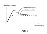
- FIG. 3 is an illustration of a graph showing the sensitivity of a geophone versus frequency, with and without a shunt resistor.
- the present invention is illustrated by a number of preferred embodiments directed to ocean bottom systems, it is not intended that these illustrations be a limitation on the scope or applicability of the present invention. Apart from ocean bottom systems, the present invention is also applicable other applications such as both land and shallow water operations as well as to seismic streamers. Further, various parts of the present invention have not been drawn to scale. Certain dimensions have been exaggerated in relation to other dimensions in order to provide a clearer illustration and understanding of the present invention.
- a method for compensating for the effect of gravity on seismic sensors such as geophones and a substantially gravity effect-free geophone assembly and seismic sensor are provided.
- FIG. 1 illustrated is a schematic showing the method for at least partially compensating for the effect of gravity on seismic sensors such as geophones.
- the preferred method includes the steps of, first, providing a seismic sensor such as a geophone 100 , which may be any conventional geophone, for example one having a coil of electrical wire suspended from a spring in a DC magnetic field, in the center of permanent magnets.
- a seismic sensor in accordance with the preferred embodiment can automatically compensate for the tilt of the sensor with reference to gravity.
- the preferred seismic sensor can provide reliable and accurate seismic measurements regardless of its tilt with reference to gravity (ie vertical or horizontal deployment).
- FIG. 2 illustrated is a schematic circuit diagram of a preferred embodiment of a seismic sensor 200 which includes a primary sensor 100 which forms part of a geophone.
- the primary sensor 100 has a coil placed in a magnetic field such that the coil is operatively responsive to seismic movements so as to generate a seismic signal.
- the primary sensor 100 is adapted to measure seismic movements of, for example, a sea bed, the ground, etc.
- the primary sensor 100 has an axis of sensitivity 105 which is the axis along which seismic movements are measured.
- the axis of sensitivity 105 of the primary sensor 100 is shown as horizontal in FIG. 2 .
- An accelerometer functions as an auxiliary sensor 210 which generates a tilt signal indicative of the tilt of the sensor 210 with reference to the local gravitational field.
- the output signal provided by the auxiliary sensor 210 is indicative of whether the auxiliary sensor 210 is tilted vertically upwards, vertically downwards, or somewhere in between those two extremes.
- Another preferred embodiment makes use of a tilt sensor.
- the output of the tilt sensor is given by a function which is substantially equal to the following term:
- the auxiliary sensor 210 takes the form of a tilt sensor 210 with an axis of sensitivity 220 parallel to the axis of sensitivity 105 of the geophone 100 .
- the tilt sensor 210 is preferably provided by any low cost micro-machined electro mechanical system (MEMS) accelerometer, for example the ones without electromechanical feedback that have been developed recently for various commercial applications such as in the automotive industry.
- MEMS micro-machined electro mechanical system
- Those accelerometers, such as ADXL-05 by Analog Device have a typical resolution of about 1 mG which is much too high for a seismic application (ie to function as the primary sensor in the present invention) but can be used as tilt sensors with an overall resolution of better than 5 degrees.
- the tilt sensor 210 is responsive to the local gravitational field so as to generate a DC tilt signal.
- This in combination with a low pass filter 250 , functions as a current generator which provides a current to the coil of the primary sensor 100 . It will be appreciated by those skilled in the art that a current is caused by a voltage and hence the scope of the term “current generator” as used in this document is to be construed as including a “voltage generator”.
- the current provided by the current generator induces a force on the coil that at least partially compensates for the downwards force on the coil due to gravity.
- the compensation provided by the current is sufficient to effectively bring the coil of the primary sensor 100 to its operative position within the relevant tolerances as required for accurate performance. This ameliorates or more preferably effectively eliminates the gravitational effect on the performance of the primary sensor 100 .
- less care is required to deploy the preferred embodiment of the invention as compared to the prior art.
- use of the preferred embodiment avoids the prior art requirement to use the appropriate sensor for the required deployment orientation. Instead, the preferred embodiment is effective for any deployment orientation.
- Geophone sensitivity is normally defined as within 2% for close tolerance geophones. This corresponds to a compensation of orientation within 3 degrees. If a 5 degree resolution of the tilt sensor 210 is added, the present invention allows for gravity compensation within better than 10 degrees, which is less than the 20 degrees of tilt a usual geophone can handle. Therefore, no additional calibration process is needed to match the tilt sensor 210 to the geophone 100 . This eases the manufacturing requirements for the preferred embodiment.
- the DC output of the tilt sensor 210 in combination with the low pass filter 250 , is used to generate the DC current in the geophone coil to induce the force on the moving mass that will at least partially compensate for the weight of the electrical coil.
- an ideal geophone with a sensitivity of, say, 27 V/(m/s) when used as an actuator, generates a force on the coil of 27 N/A. Therefore, the maximum current needed to compensate the weight of the typically 11 grams of geophone coil is 11 times 9.81 divided by 27 which equals 4 mA.
- the geophone 100 is used together with a shunt resistor 230 to damp the main resonance of the geophone 100 as shown in FIG. 3 , thus providing a smooth frequency response.
- coil resistance is about 400 ohms and a 70% damping of the resonance is usually achieved by use of a shunt resistance of about 1000 ohms.
- the preferred embodiment of the present invention applies a DC voltage between the geophone 100 and shunt resistor 230 at a coupling node 240 .
- the maximum voltage needed to induce the 4 mA current for compensating the full gravity field is 1400 times 0.004, which equals 5.6 V, and the power consumption is then 5.6 times 0.004 which equals 22 mWatts.
- Some commercial tilt sensors 210 have a power consumption as low as 10 mWatts. Therefore the total additional power needed is in the order of 30 mWatts (22 mWatts plus 10 mWatts) per channel, which is about one tenth of power consumption for modem MEMS prior art solutions.
- the DC Voltage at the coupling node 240 is determined by low pass filtering the tilt signal with adequate gain, that is, having a low pass filter 250 placed in series with, and between, the tilt sensor 210 and the shunt resistor 230 .
- the low pass filter 250 has a low pass cut off frequency lower than the resonance frequency of the geophone 100 , and preferably much lower.
- the low pass filter 250 has a cut-off frequency lower than the frequency of interest for the seismic signal.
- the low pass filter 250 also has a long time constant, for example in the order of minutes.
- the preferred embodiment of the present invention includes a preamplifier 260 , such as an operational amplifier, for producing a seismic output signal to recorded.
- the seismic output signal is proportional to the seismic signal of the primary sensor 100 .
- the method further includes the steps of detecting the gravity field by using the accelerometer 110 thus producing a tilt signal; low bass filtering the tilt signal produced by the accelerometer 210 to generate the external bias current 110 ; and applying the external bias current to the electrical coil of the geophone 100 , all within the step of generating the external bias current 110 to the electrical coil of the geophone 100 .
- the method of the preferred embodiment of the present invention also includes the step of damping the resonance of the primary sensor 100 .
- a gravity compensated seismic output signal is preferably generated by amplifying the output of the primary sensor 100 , for example by use of an operational amplifier 260 .
- the low pass filter used in method has a cutoff frequency which is lower than a resonance frequency of said primary sensor.
- geophones are usually best adapted to function at frequencies which are above a given resonance frequency and it is generally preferable for the resonance frequency to be as low as possible. It is also usually preferable for geophones to have a response linearity that is as high as possible. For these reasons, it is typically preferable for the stroke of the coil in geophones to be limited to a few millimeters. In the prior art, a short stroke, combined with the use of a supple spring, can undersirably allow gravitational forces to displace the coil away from its optimum neutral resting position. More particularly, it is generally the component of the gravitational force which acts along the axis of sensitivity which causes the undesirable displacement of the coil in prior art geophones.
Landscapes
- Engineering & Computer Science (AREA)
- Remote Sensing (AREA)
- Physics & Mathematics (AREA)
- Life Sciences & Earth Sciences (AREA)
- Acoustics & Sound (AREA)
- Environmental & Geological Engineering (AREA)
- Geology (AREA)
- General Life Sciences & Earth Sciences (AREA)
- General Physics & Mathematics (AREA)
- Geophysics (AREA)
- Geophysics And Detection Of Objects (AREA)
Abstract
Description
-
- sin (θ)
- where θ is the angle of inclination of the axis of sensitivity of the tilt sensor relative to the local gravitational field.
This allows the compensation for gravitational effects achieved within some preferred embodiments to be effectively perfect to within acceptable tolerances. In other preferred embodiments the output of the tilt sensor is given by a function which is substantially proportional to, or substantially includes, the sin(θ) term.
Claims (27)
Applications Claiming Priority (3)
| Application Number | Priority Date | Filing Date | Title |
|---|---|---|---|
| AUPS2256A AUPS225602A0 (en) | 2002-05-10 | 2002-05-10 | Improved seismic sensors |
| AUPS2256 | 2002-05-10 | ||
| PCT/AU2003/000562 WO2003096071A1 (en) | 2002-05-10 | 2003-05-09 | Improved seismic sensors |
Publications (2)
| Publication Number | Publication Date |
|---|---|
| US20050201206A1 US20050201206A1 (en) | 2005-09-15 |
| US7292504B2 true US7292504B2 (en) | 2007-11-06 |
Family
ID=3835828
Family Applications (1)
| Application Number | Title | Priority Date | Filing Date |
|---|---|---|---|
| US10/513,901 Expired - Fee Related US7292504B2 (en) | 2002-05-10 | 2003-05-09 | Seismic sensors |
Country Status (3)
| Country | Link |
|---|---|
| US (1) | US7292504B2 (en) |
| AU (1) | AUPS225602A0 (en) |
| WO (1) | WO2003096071A1 (en) |
Cited By (6)
| Publication number | Priority date | Publication date | Assignee | Title |
|---|---|---|---|---|
| US20090056411A1 (en) * | 2007-08-28 | 2009-03-05 | Nicolas Goujon | Calibrating an accelerometer |
| US20100195438A1 (en) * | 2009-02-05 | 2010-08-05 | Nicolas Goujon | Deriving tilt-corrected seismic data in a multi-axis seismic sensor module |
| US20100202249A1 (en) * | 2009-02-06 | 2010-08-12 | Nicolas Goujon | Particle motion sensor-based streamer positioning system |
| US20100296366A1 (en) * | 2009-05-25 | 2010-11-25 | Schlumberger Technology Corporation | Methods and systems for seismic signal detection |
| US9010170B2 (en) | 2010-08-16 | 2015-04-21 | Westerngeco L.L.C. | Method and apparatus to test an accelerometer |
| US9217805B2 (en) | 2010-10-01 | 2015-12-22 | Westerngeco L.L.C. | Monitoring the quality of particle motion data during a seismic acquisition |
Families Citing this family (14)
| Publication number | Priority date | Publication date | Assignee | Title |
|---|---|---|---|---|
| AUPS225602A0 (en) * | 2002-05-10 | 2002-06-13 | Thales Underwater Systems Pty Limited | Improved seismic sensors |
| DE10344558A1 (en) * | 2003-09-25 | 2005-05-12 | Send Signal Elektronik Gmbh | Method and device for detecting seismic movements |
| CN100363753C (en) * | 2004-06-28 | 2008-01-23 | 陕西超波传感器有限责任公司 | Novel composite earthquake demodulator |
| CN100351649C (en) * | 2004-06-28 | 2007-11-28 | 陕西超波传感器有限责任公司 | Ocean earthquake demodulator |
| US7929379B2 (en) * | 2008-07-27 | 2011-04-19 | Schlumberger Technology Corporation | Methods and systems for seismic sensors |
| US8139439B2 (en) | 2009-03-11 | 2012-03-20 | Schlumberger Technology Corporation | Methods and systems for seismic sensor calibration |
| EP2261530A1 (en) * | 2009-06-12 | 2010-12-15 | Nederlandse Organisatie voor toegepast -natuurwetenschappelijk onderzoek TNO | An active vibration isolation and damping system |
| US8614928B2 (en) * | 2009-12-31 | 2013-12-24 | Wireless Seismic, Inc. | Wireless data acquisition system and method using self-initializing wireless modules |
| CN101813785A (en) * | 2010-05-10 | 2010-08-25 | 中南大学 | Sensor tailstock for seismic exploration or vibration test |
| CA2841455A1 (en) * | 2011-07-19 | 2013-01-24 | Conocophillips Company | Multiple frequency geophone strings |
| EP2690468B1 (en) * | 2012-07-27 | 2019-03-27 | Sercel | A streamer for seismic prospection comprising tilt compensation of directional sensors |
| CN110243343B (en) * | 2018-03-09 | 2022-07-29 | 精工爱普生株式会社 | Sensor module, inclinometer, and structure monitoring device |
| CN111239154A (en) * | 2020-01-18 | 2020-06-05 | 哈尔滨工业大学 | Transverse differential dark field confocal microscopic measurement device and method thereof |
| CN115128664B (en) * | 2022-09-01 | 2022-11-08 | 中国科学院地质与地球物理研究所 | Seismic acquisition system based on frequency domain broadening MEMS sensor |
Citations (8)
| Publication number | Priority date | Publication date | Assignee | Title |
|---|---|---|---|---|
| US2695165A (en) | 1950-07-14 | 1954-11-23 | Hughes Aircraft Co | Electromagnetic accelerometer |
| GB1526289A (en) | 1975-12-09 | 1978-09-27 | Shell Int Research | Geophone and method of checking characteristics of the same or of a seismic string comprising such geophone |
| EP0264509A1 (en) | 1985-04-16 | 1988-04-27 | Societe De Prospection Electrique Schlumberger | Optical seismic detector |
| US5475652A (en) | 1993-06-30 | 1995-12-12 | I/O Exploration Products | Dual gimbal geophone |
| US5606124A (en) * | 1996-05-20 | 1997-02-25 | Western Atlas International, Inc. | Apparatus and method for determining the gravitational orientation of a well logging instrument |
| EP1061382A1 (en) | 1999-06-07 | 2000-12-20 | Institut Francais Du Petrole | Elastic-wave sensor electrically compensated for the effects of inclination |
| US6353577B1 (en) * | 1996-09-20 | 2002-03-05 | Jacques Joseph Henri Orban | Seismic sensor units |
| WO2003096071A1 (en) * | 2002-05-10 | 2003-11-20 | Thales Underwater Systems Pty Limited | Improved seismic sensors |
-
2002
- 2002-05-10 AU AUPS2256A patent/AUPS225602A0/en not_active Abandoned
-
2003
- 2003-05-09 WO PCT/AU2003/000562 patent/WO2003096071A1/en not_active Application Discontinuation
- 2003-05-09 US US10/513,901 patent/US7292504B2/en not_active Expired - Fee Related
Patent Citations (10)
| Publication number | Priority date | Publication date | Assignee | Title |
|---|---|---|---|---|
| US2695165A (en) | 1950-07-14 | 1954-11-23 | Hughes Aircraft Co | Electromagnetic accelerometer |
| GB1526289A (en) | 1975-12-09 | 1978-09-27 | Shell Int Research | Geophone and method of checking characteristics of the same or of a seismic string comprising such geophone |
| EP0264509A1 (en) | 1985-04-16 | 1988-04-27 | Societe De Prospection Electrique Schlumberger | Optical seismic detector |
| US5475652A (en) | 1993-06-30 | 1995-12-12 | I/O Exploration Products | Dual gimbal geophone |
| US5606124A (en) * | 1996-05-20 | 1997-02-25 | Western Atlas International, Inc. | Apparatus and method for determining the gravitational orientation of a well logging instrument |
| US6353577B1 (en) * | 1996-09-20 | 2002-03-05 | Jacques Joseph Henri Orban | Seismic sensor units |
| EP1061382A1 (en) | 1999-06-07 | 2000-12-20 | Institut Francais Du Petrole | Elastic-wave sensor electrically compensated for the effects of inclination |
| US6412592B1 (en) | 1999-06-07 | 2002-07-02 | Institut Francais Du Petrole | Electrically inclination compensated device for picking up elastic waves |
| WO2003096071A1 (en) * | 2002-05-10 | 2003-11-20 | Thales Underwater Systems Pty Limited | Improved seismic sensors |
| US20050201206A1 (en) * | 2002-05-10 | 2005-09-15 | Francois Luc | Seismic sensors |
Cited By (17)
| Publication number | Priority date | Publication date | Assignee | Title |
|---|---|---|---|---|
| US20090056411A1 (en) * | 2007-08-28 | 2009-03-05 | Nicolas Goujon | Calibrating an accelerometer |
| US8136383B2 (en) | 2007-08-28 | 2012-03-20 | Westerngeco L.L.C. | Calibrating an accelerometer |
| WO2010091108A3 (en) * | 2009-02-05 | 2010-11-25 | Geco Technology B.V. | Deriving tilt-corrected seismic data in a multi-axis seismic sensor module |
| US8199611B2 (en) | 2009-02-05 | 2012-06-12 | Westerngeco L.L.C. | Deriving tilt-corrected seismic data in a multi-axis seismic sensor module |
| CN102308230B (en) * | 2009-02-05 | 2014-10-15 | 格库技术有限公司 | Deriving tilt-corrected seismic data in a multi-axis seismic sensor module |
| EP2394186A2 (en) * | 2009-02-05 | 2011-12-14 | Geco Technology B.V. | Deriving tilt-corrected seismic data in a multi-axis seismic sensor module |
| CN102308230A (en) * | 2009-02-05 | 2012-01-04 | 格库技术有限公司 | Deriving tilt-corrected seismic data in a multi-axis seismic sensor module |
| EP2394186A4 (en) * | 2009-02-05 | 2013-12-04 | Geco Technology Bv | Deriving tilt-corrected seismic data in a multi-axis seismic sensor module |
| US20100195438A1 (en) * | 2009-02-05 | 2010-08-05 | Nicolas Goujon | Deriving tilt-corrected seismic data in a multi-axis seismic sensor module |
| US20100202249A1 (en) * | 2009-02-06 | 2010-08-12 | Nicolas Goujon | Particle motion sensor-based streamer positioning system |
| US9829595B2 (en) | 2009-02-06 | 2017-11-28 | Westerngeco L.L.C. | Particle motion sensor-based streamer positioning system |
| US20100296366A1 (en) * | 2009-05-25 | 2010-11-25 | Schlumberger Technology Corporation | Methods and systems for seismic signal detection |
| US8305845B2 (en) | 2009-05-25 | 2012-11-06 | Schlumberger Technology | Methods and systems for seismic signal detection |
| US8125852B2 (en) * | 2009-05-25 | 2012-02-28 | Schlumberger Technology Corporation | Methods and systems for seismic signal detection |
| US8687465B2 (en) | 2009-05-25 | 2014-04-01 | Schlumberger Technology Corporation | Methods and systems for seismic signal detection |
| US9010170B2 (en) | 2010-08-16 | 2015-04-21 | Westerngeco L.L.C. | Method and apparatus to test an accelerometer |
| US9217805B2 (en) | 2010-10-01 | 2015-12-22 | Westerngeco L.L.C. | Monitoring the quality of particle motion data during a seismic acquisition |
Also Published As
| Publication number | Publication date |
|---|---|
| WO2003096071A1 (en) | 2003-11-20 |
| US20050201206A1 (en) | 2005-09-15 |
| AUPS225602A0 (en) | 2002-06-13 |
Similar Documents
| Publication | Publication Date | Title |
|---|---|---|
| US7292504B2 (en) | Seismic sensors | |
| US8687465B2 (en) | Methods and systems for seismic signal detection | |
| AU2008239686B2 (en) | System and method for marine seismic surveying | |
| Laine et al. | Benefits of MEMS based seismic accelerometers for oil exploration | |
| CA2694886C (en) | Methods and systems for seismic sensor calibration | |
| US20070242563A1 (en) | Geophone calibration technique | |
| EP0434702B1 (en) | A geophone system | |
| US6075754A (en) | Single-coil force balance velocity geophone | |
| RU2571164C2 (en) | Gradient meter | |
| US7406002B2 (en) | Method and apparatus for the acquisition of seismic movements | |
| US2674885A (en) | Gravity meter motion compensator | |
| US5384753A (en) | Self-orienting seismic detector | |
| US9010170B2 (en) | Method and apparatus to test an accelerometer | |
| US20030081501A1 (en) | Reservoir evaluation apparatus and method | |
| US4446541A (en) | Rotational geophone | |
| US6307809B1 (en) | Geophone with optical fiber pressure sensor | |
| EP1061382B1 (en) | Elastic-wave sensor electrically compensated for the effects of inclination | |
| US3412374A (en) | Short period seismic system with long period response | |
| JPH0627135A (en) | Dynamic-electricity type accelerometer | |
| Liu et al. | A three-component borehole seismometer for earthquake seismology | |
| Klaassen et al. | ELECTRONIC ACCELERATION‐SENSITIVE GEOPHONE FOR SEISMIC PROSPECTING | |
| Melton | Earthquake seismograph development: A modern history—Part 1 | |
| Melton et al. | Inertial seismograph design-limitations in principle and practice (or how not to build a sensitive seismograph) | |
| Kamata | High precision geophone calibration | |
| JP3240660U (en) | accelerometer with geophone |
Legal Events
| Date | Code | Title | Description |
|---|---|---|---|
| AS | Assignment |
Owner name: THALES UNDERWATER SYSTEMS PTY LIMITED, AUSTRALIA Free format text: ASSIGNMENT OF ASSIGNORS INTEREST;ASSIGNOR:LUC, FRANCOIS;REEL/FRAME:016413/0456 Effective date: 20030529 |
|
| AS | Assignment |
Owner name: SERCEL AUSTRALIA PTY LTD., AUSTRALIA Free format text: ASSIGNMENT OF ASSIGNORS INTEREST;ASSIGNOR:THALES UNDERWATER SYSTEMS PTY LIMITED;REEL/FRAME:016511/0921 Effective date: 20050404 |
|
| STCF | Information on status: patent grant |
Free format text: PATENTED CASE |
|
| CC | Certificate of correction | ||
| FPAY | Fee payment |
Year of fee payment: 4 |
|
| FPAY | Fee payment |
Year of fee payment: 8 |
|
| FEPP | Fee payment procedure |
Free format text: MAINTENANCE FEE REMINDER MAILED (ORIGINAL EVENT CODE: REM.); ENTITY STATUS OF PATENT OWNER: LARGE ENTITY |
|
| LAPS | Lapse for failure to pay maintenance fees |
Free format text: PATENT EXPIRED FOR FAILURE TO PAY MAINTENANCE FEES (ORIGINAL EVENT CODE: EXP.); ENTITY STATUS OF PATENT OWNER: LARGE ENTITY |
|
| STCH | Information on status: patent discontinuation |
Free format text: PATENT EXPIRED DUE TO NONPAYMENT OF MAINTENANCE FEES UNDER 37 CFR 1.362 |
|
| FP | Lapsed due to failure to pay maintenance fee |
Effective date: 20191106 |