US7280161B2 - Noise reduction circuit and method - Google Patents
Noise reduction circuit and method Download PDFInfo
- Publication number
- US7280161B2 US7280161B2 US10/981,776 US98177604A US7280161B2 US 7280161 B2 US7280161 B2 US 7280161B2 US 98177604 A US98177604 A US 98177604A US 7280161 B2 US7280161 B2 US 7280161B2
- Authority
- US
- United States
- Prior art keywords
- noise reduction
- noise
- correlation
- utilizing
- inter
- Prior art date
- Legal status (The legal status is an assumption and is not a legal conclusion. Google has not performed a legal analysis and makes no representation as to the accuracy of the status listed.)
- Active, expires
Links
Images


Classifications
-
- H—ELECTRICITY
- H04—ELECTRIC COMMUNICATION TECHNIQUE
- H04N—PICTORIAL COMMUNICATION, e.g. TELEVISION
- H04N5/00—Details of television systems
- H04N5/14—Picture signal circuitry for video frequency region
- H04N5/21—Circuitry for suppressing or minimising disturbance, e.g. moiré or halo
Definitions
- the present invention generally relates to a noise reduction circuit and method. More specifically, the present invention relates to a noise reduction circuit and method that can be applied to a video display apparatus or a video recording/reproducing apparatus, for example.
- JP 2002-223374A discloses a noise reduction method, in which pixels of the same position in an image in a plurality of frames of an input video signal are extracted, noise is determined based on a signal change of the pixels between the frames, and a reduction procedure is performed.
- a noise reduction method in which pixels of the same position in an image in a plurality of frames of an input video signal are extracted, noise is determined based on a signal change of the pixels between the frames, and a reduction procedure is performed.
- the time difference at which the signal change is obtained is large. Further, it is not possible to reduce noise effectively without using a complex circuit for moving parts.
- yet another problem in the above-described conventional method was that a time difference between an audio signal and a video signal is generated because a delay of at least one frame arises in the noise reduction process and additional and considerable memory capacity and complex circuits are needed in correcting the delay.
- a noise reduction circuit includes a video data storage device, a plurality of correlation-utilizing noise reduction devices, a selecting/combining control signal production device, and a selecting/combining device.
- the video data storage device stores noise-reduced video data of a directly preceding predetermined period.
- Each of the correlation-utilizing noise reduction devices forms and outputs noise-reduced data by utilizing a correlation based on a difference between two sets of data.
- the two sets of data are data of a pixel of the input video data that are subjected to noise reduction, and data received from the video data storage device of a pixel that is shifted by a predetermined amount in a time direction and/or spatial direction with respect to the pixel that is subjected to noise reduction.
- Each of the correlation-utilizing noise reduction devices forms and outputs a difference cause discriminating signal indicating whether the difference is due to noise or whether the difference is due to a valid change of the image.
- the difference cause discriminating signal is formed based on a temporal change of the difference.
- the plurality of correlation-utilizing noise reduction devices has different combinations of shift amounts in the time direction and/or the space direction.
- the selecting/combining control signal production device forms and outputs a selecting/combining control signal representing a method to determine final noise-reduced video data based on the difference cause discriminating signals from each of the correlation-utilizing noise reduction devices.
- the selecting/combining device obtains the final noise-reduced video data by selecting or combining the noise-reduced data from the plurality of correlation-utilizing noise reduction devices based on the selecting/combining control signal.
- a noise reduction method includes a video data storage step, a plurality of correlation-utilizing noise reduction steps, a selecting/combining control signal production step, and a selecting/combining step.
- the video data storage step is provided to store noise-reduced video data of a directly preceding predetermined period.
- Each of the correlation-utilizing noise reduction steps is provided to form and to output noise-reduced data by utilizing a correlation based on a difference between two sets of data.
- the two sets of data are data of a pixel of the input video data that is subjected to noise reduction, and data produced by the video data storage step of a pixel that is shifted by a predetermined amount in a time direction and/or spatial direction with respect to the pixel that is subjected to noise reduction.
- Each of the correlation-utilizing noise reduction steps forms and outputs a difference to cause a discriminating signal that indicates whether the difference is due to noise or whether the difference is due to a valid change of the image.
- the difference causes the discriminating signal to be formed based on a temporal change of the difference.
- the plurality of correlation-utilizing noise reduction steps has different combinations of shift amounts in the time direction and/or the space direction.
- the selecting/combining control signal production step forms and outputs a selecting/combining control signal that represents a method for determining final noise-reduced video data based on the difference cause discriminating signals from the plurality of correlation-utilizing noise reduction steps.
- the selecting/combining step obtains the final noise-reduced video data by selecting or combining the noise-reduced data from the plurality of correlation-utilizing noise reduction steps, based on the selecting/combining control signal.
- the noise reduction circuit and method of the present invention it is possible to reduce memory capacity because the plurality of correlation-utilizing noise reduction devices or steps uses a common video data storage device. It is also possible to suppress process delays to about the maximum time shift utilized for correlation. It is further possible to reduce noise effectively with a simple structure regardless of the partial content of the image because the final output data are obtained by selecting and/or combining the output data of the plurality of correlation-utilizing noise reduction devices or steps.
- FIG. 1 is a view of a block diagram showing a configuration of a noise reduction circuit according to a first preferred embodiment of the present invention
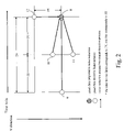
- FIG. 2 is a view of a diagram showing a relation along a time axis direction and a vertical direction of past pixel data that are utilized to reduce noise and pixel data that are subjected to the noise reduction of the noise reduction circuit;
- FIG. 3 is a view of a table listing the presence and the size of shifts in the time direction and the vertical direction between the two data points that are input into four different noise reduction devices of the noise reduction circuit;
- FIG. 4 is a view of a table illustrating the logic behind the selection or combination of noise-reduced data with a selecting/combining device of the noise reduction circuit;
- FIG. 5 is a view of a flowchart showing a process to form the selecting/combining control signal of a movement/edge detection correction signal production device of the noise reduction circuit;
- FIG. 6 is a view of a block diagram showing a configuration of a noise reduction circuit according to a second preferred embodiment of the present invention.
- FIG. 7 is a view of a table illustrating the logic behind the selection or combination of the noise-reduced data of a selecting/combining device of the noise reduction circuit of FIG. 6 ;
- FIG. 8 is a view of a flowchart showing the process to form the selecting/combining control signal of a movement/edge detection correction signal production device of the noise reduction circuit of FIG. 6 .
- a video signal (video data) that is processed by the noise reduction circuit of the first embodiment can be a composite video signal or a component signal such as a luminance signal, a color signal, or a color-difference signal.
- the signal is preferably an interlaced signal and the number of lines per frame does not matter.
- data that are input into the noise reduction circuit of the first embodiment are entered as a digital signal (video data), but the bit number of the pixel data does not matter.
- the sampling frequency of the digital signal also does not matter.
- the noise reduction circuit of the first embodiment can be included in an apparatus that processes video signals (video data) that are reproduced from a recording medium, an apparatus that processes video signals (video data) that are received from a network, an apparatus that processes broadcast video signals (video data), or an apparatus that processes video signals (video data) taken with a video camera.
- FIG. 1 is a view of a block diagram showing the configuration of the noise reduction circuit of the first embodiment.
- the noise reduction circuit of the first embodiment includes a frame memory 1 (video data storage device), an inter-frame noise reduction device 2 , two inter-field noise reduction devices 3 and 4 , an inter-line noise reduction device 5 , a movement/edge detection correction signal production device 6 , and a selecting/combining device 7 .
- the inter-field noise reduction device 3 is referred to as “the first inter-field noise reduction device”
- the inter-field noise reduction device 4 is referred to as “the second inter-field noise reduction device.”
- the frame memory 1 stores at least one frame worth of noise-reduced video data that were output from the selecting/combining device 7 .
- the frame memory 1 outputs the pixel data of the previous frame that are presently subjected to noise reduction (video image data) to the inter-frame noise reduction device 2 , respectively outputs the data of two pixels of the previous field to the first inter-field noise reduction device 3 and the second inter-field noise reduction device 4 , and outputs the pixel data of the previous line (1 horizontal scanning line) to the inter-line noise reduction device 5 .
- FIG. 2 is a view of a diagram showing a relation between pixel data that are subjected to noise reduction and previous pixel data that are used in reducing noise, plotted along a time axis direction and a Vertical direction (V direction).
- Pixel data 9 are the pixel data of one frame before (that is, two fields (field periods) before; 2V before) pixel data 8 that are subjected to the noise reduction and are output to the inter-frame noise reduction device 2 .
- the pixel data 9 of the previous frame are in the same position on a display as the pixel data 8 that are subjected to the noise reduction.
- Pixel data 10 and 111 are the pixel data of one field (period) (1V) before the pixel data 8 that are subjected to the noise reduction and are output to the first inter-field noise reduction device 3 and the second inter-field noise reduction device 4 .
- the pixel data 10 that are output to the first inter-field noise reduction device 3 are located in the same position on a display with regard to the horizontal direction as the pixel data 8 that are subjected to the noise reduction (although it may be shifted by up to 1 ⁇ 2 pixel pitch). However, the pixel data 10 are located 1 ⁇ 2 line higher in the vertical direction.
- the pixel data 11 that are output to the second inter-field noise reduction device 4 are located in the same position on a display with regard to the horizontal direction as the pixel data 8 that are subjected to the noise reduction (although they may be shifted by up to 1 ⁇ 2 pixel pitch), but the pixel data 11 are located 1 ⁇ 2 line lower in the vertical direction.
- Pixel data 12 are the pixel data of the one line before (one horizontal scanning period; 1H) the pixel data 8 that are subjected to the noise reduction and are output to the inter-line noise reduction device 5 .
- the pixel data 12 are located in the same position on a display in the horizontal direction as the pixel data 8 that are subjected to the noise reduction, but are located one line above the pixel data 8 in the vertical direction.
- the inter-frame noise reduction device 2 forms inter-frame noise-reduced data and an inter-frame movement detection signal from the input video data and the 1-frame-delay data from the frame memory 1 (the formation will be explained in the section discussing the operation of the noise reduction circuit). Further, the inter-frame noise reduction device 2 outputs the inter-frame noise-reduced data to the selecting/combining device 7 and the inter-frame movement detection signal to the movement/edge detection correction signal production device 6 .
- the first inter-field noise reduction device 3 forms inter-field noise-reduced data A and an inter-field movement/edge detection signal A from the input video data and 1-field-delay data A from the frame memory 1 (see pixel data 10 in FIG. 2 ) (the formation will be explained in the section discussing the operation of the noise reduction circuit). Further, the first inter-field noise reduction device 3 outputs the inter-field noise-reduced data A to the selecting/combining device 7 and the inter-field movement/edge detection signal A to the movement/edge detection correction signal production device 6 .
- the second inter-field noise reduction device 4 forms inter-field noise-reduced data B and an inter-field movement/edge detection signal B from the input video data and 1-field-delay data B from the frame memory 1 (see pixel data 11 in FIG. 2 ) (the formation will be explained in the section discussing the operation of the noise reduction circuit). Further, the second inter-field noise reduction device 4 outputs the inter-field noise-reduced data B to the selecting/combining device 7 and the inter-field movement/edge detection signal B to the movement/edge detection correction signal production device 6 .
- the inter-line noise reduction device 5 forms inter-line noise-reduced data and an inter-line edge detection signal from the input video data and 1-line-delay data from the frame memory 1 (the formation will be explained in the section discussing the operation of the noise reduction circuit). Further, the inter-line noise reduction device 5 outputs the inter-line noise-reduced data to the selecting/combining device 7 and the inter-line edge detection signal to the movement/edge detection correction signal production device.
- the movement/edge detection correction signal production device 6 forms a movement/edge detection correction signal from the inter-frame movement detection signal, the inter-field movement/edge detection signal A, the inter-field movement/edge detection signal B, and the inter-line edge detection signal. Further, the movement/edge detection correction signal production device 6 outputs the movement/edge detection correction signal as a control signal to the selecting/combining device 7 .
- the selecting/combining device 7 selects and/or combines the inter-frame noise-reduced data, the inter-field noise-reduced data A, the inter-field noise-reduced data B, and the inter-line noise-reduced data from the four noise reduction devices 2 , 3 , 4 , and 5 , in accordance with the movement/edge detection correction signal from the movement/edge detection correction signal production device 6 . Further, the selecting/combining device 7 outputs the selected/combined data as the noise-reduced video data. The noise-reduced video data are output to the next stage and also given to the frame memory 1 .
- the noise reduction devices 2 to 5 respectively conduct the following processes of forming the noise-reduced data for the pixel that is subjected to the noise reduction.
- the inter-frame noise reduction device 2 first determines the absolute value of the difference (or difference squared; the same is true below) between the input video data (pixel data) 8 of the pixel that is subjected to the noise reduction and the 1-frame-delay data 9 (the pixel data of the one frame before) that are output from the frame memory 1 .
- the inter-frame noise reduction device 2 compares the absolute difference value to a threshold value for noise/movement discrimination. The difference is determined to be due to noise if the absolute difference value is smaller than the threshold value, and the difference is determined to be due to a movement of an image portion if the absolute difference value is larger than the threshold value.
- the inter-frame noise reduction device 2 determines the difference to be due to noise, based on the absolute difference value, the inter-frame noise reduction device 2 outputs inter-frame noise-reduced data obtained by removing the noise component from the input video data (pixel data) 8 .
- the inter-frame noise reduction device 2 determines the difference to be due to a movement, based on the absolute difference, the inter-frame noise reduction device 2 outputs the input video data (pixel data) 8 as are as the inter-frame noise-reduced data.
- the noise component removed from the input video data (pixel data) 8 can be the difference itself as described above, the value of multiplying the difference by a weighting coefficient of predetermined value, or the weighted average of the differences for a plurality of the immediately preceding pixels which were determined to be due to noise.
- the inter-frame noise reduction device 2 determines the difference to be due to a movement, based on the absolute difference value, the inter-frame noise reduction device 2 obtains a difference amount level (smoothened value) by passing the absolute difference value through a low-pass filter. Further, the inter-frame noise reduction device 2 forms and outputs an inter-frame movement detection signal which includes a data difference amount that has been determined as the movement and a movement discriminating signal (movement yes/no) that is determined from the difference amount level and the sign of the difference.
- a difference amount level smoothened value
- the movement discriminating signal of the inter-frame movement detection signal is not simply set to “movement: yes”, but the content of the movement discriminating signal (“movement: yes” or “movement: no”) is determined in accordance with the change that includes the sign (plus or minus) of the difference amount level that has been passed through the low-pass filter.
- the noise is random but there is a certain tendency in the change of the video data of the same pixel in the case of a movement.
- the content of the movement discriminating signal that is included in the inter-frame movement detection signal is therefore determined based on the difference amount level that is obtained through the low-pass filter.
- the first inter-field noise reduction device 3 first determines the absolute value of the difference between the input video data (pixel data) 8 of the pixel that is subjected to the noise reduction and the 1-field-delay data 10 that are output from the frame memory 1 .
- the first inter-field noise reduction device 3 compares the absolute difference value to a threshold value for discriminating between noise and movement/edges.
- the difference is determined to be due to noise if the absolute difference value is smaller than the threshold value and the difference is determined to be due to a movement of the image portion or an edge if the absolute difference value is equal to or larger than the threshold value.
- the technical idea of trying to distinguish between noise and movement by comparing the absolute difference value with the threshold value is the same as for the inter-frame noise reduction device 2 .
- the two data points used by the first inter-field noise reduction device 3 to determine the absolute difference value that is, the input video data (pixel data) 8 and the pixel of 1-field-delay data 10 that is output from the frame memory 1 have the same horizontal position on a display but are shifted by 1 ⁇ 2 line in the vertical direction. Consequently, also if there is an edge of a stationary object within this width of shift between the pixel positions in the image, then the absolute difference becomes large. Consequently, the reason why the absolute difference value becomes equal to or larger than the threshold value arises not only from movements but also from the presence of edges.
- the first inter-field noise reduction device 3 determines that the difference is due to noise based on the absolute difference value, then the first inter-field noise reduction device 3 outputs inter-field noise-reduced data A obtained by removing the noise component from the input video data (pixel data) 8 .
- the first inter-field noise reduction device 3 determines that the difference is due to a movement or an edge, based on the absolute difference value, then the first inter-field noise reduction device 3 outputs the input video data (pixel data) 8 as they are as the first inter-field noise-reduced data A.
- the noise component removed from the input video data (pixel data) 8 can be the difference itself as described above, the value of multiplying the difference by a weighting coefficient of predetermined value, or the weighted average of the differences for a plurality of the immediately preceding pixels which were determined to be due to noise.
- the first inter-field noise reduction device 3 determines the difference to be due to a movement or an edge, based on the absolute difference value, the absolute difference value is passed through the low-pass filter to obtain the difference amount level (smoothened value). Further, the first inter-field noise reduction device 3 forms and outputs an inter-field movement/edge detection signal which includes a data difference amount that has been determined as either a movement or an edge and a movement/edge discriminating signal (movement/edge: yes/no) that is determined from the difference amount level and the sign of the difference.
- an inter-field movement/edge detection signal which includes a data difference amount that has been determined as either a movement or an edge and a movement/edge discriminating signal (movement/edge: yes/no) that is determined from the difference amount level and the sign of the difference.
- the second inter-field noise reduction device 4 conducts a similar process as the first inter-field noise reduction device 3 , based on the input video data (pixel data) 8 of the pixel that is subjected to the noise reduction and the 1-field-delay data 11 that are output from the frame memory 1 .
- the inter-line noise reduction device 5 first determines the absolute value of the difference between the input video data (pixel data) 8 of the pixels that are subjected to the noise reduction and 1-line-delay data 12 that is output from the frame memory 1 .
- the inter-line noise reduction device 5 compares this absolute difference value to a threshold value for noise/edge discrimination.
- the difference is determined to be due to noise if the absolute difference value is smaller than the threshold value, and the difference is determined to be due to the edge of the image portion if the absolute difference value is equal to or larger than the threshold value.
- the technical idea of trying to distinguish between noise and edges by comparing the absolute difference value with the threshold value is the same as for the first inter-field noise reduction device 3 and the second inter-field noise reduction device 4 .
- the two data points used by the inter-line noise reduction device 5 to determine the absolute difference value that is, the input video data (pixel data) 8 and the pixel of the 1-line-delay data 12 that are output from the frame memory 1 belong to the same frame and the same field, so that they cannot be used to detect movement but only to detect an edge.
- the inter-line noise reduction device 5 determines the difference to be due to noise, based on the absolute difference value, the inter-line noise reduction device 5 outputs inter-line noise-reduced data obtained by removing the noise component from the input video data (pixel data) 8 .
- the inter-line noise reduction device 5 determines the difference to be due to an edge, based on the absolute difference value, the inter-line noise reduction device 5 outputs the input video data (pixel data) 8 as they are as the inter-line noise-reduced data.
- the noise component removed from the input video data (pixel data) 8 can be the difference itself as described above, the value of multiplying the difference by a weighting coefficient of predetermined value, or the weighted average of the differences for a plurality of the immediately preceding pixels which were determined to be due to noise.
- the inter-line noise reduction device 5 determines the difference to be due to an edge, based on the absolute difference value, the absolute difference value is passed through the low-pass filter to obtain the difference amount level (smoothened value), and the inter-line noise reduction device 5 forms and outputs an inter-line edge detection signal which includes the data difference amount that has been determined as an edge and an edge discriminating signal (edge yes/no) that is determined from the difference amount level and a sign of the difference.
- FIG. 3 is a view of a table listing the presence and the size of shifts in the time direction and the vertical direction between the two data points that are input into the four different noise reduction devices 2 to 5 . It should be noted that it is assumed in FIG. 3 that there is no shift in position in the horizontal direction.
- FIG. 4 is a view of a table that explains the meaning of the control signals from the movement/edge detection correction signal production device 6 to the selecting/combining device 7 . In other words, FIG. 4 is a table that explains the logic behind the selection or combination with the selecting/combining device 7 .
- the shift in the time axis direction with respect to the pixel data 8 that are subjected to the noise reduction is relatively large at 2V (V is one field period).
- V is one field period
- a positional afterimage is generated if the difference data are used to generate the noise-reduced data, because it is not possible to correlate the data over time.
- the 1-line-delay data 12 that are related to the inter-line noise reduction device 5 although there is no shift in the time axis direction, there is a one line shift in the V direction with respect to the pixel data 8 that are subjected to the noise reduction, as shown in FIG. 3 . Consequently, as FIG. 4 shows, when there is no edge between the lines, it is possible to extract the noise component from the noise-reduced data by determining the absolute value of the difference between the 1-line-delay data 12 and the pixel data 8 that are subjected to the noise reduction. However, when there is an edge between the lines, a positional afterimage is generated if the difference data is used to generate the noise-reduced data, because it is not possible to correlate the data over the V direction.
- the movement/edge detection correction signal production device 6 thus forms a control signal used to select or to combine the noise-reduced data in such a way that the afterimage both in the time and V directions is always minimized.
- the final noise-reduced video data are obtained as the selecting/combining device 7 selects or combines the noise-reduced data from the four noise reduction devices 2 to 5 according to the control signal.
- FIG. 5 is a view of a flowchart showing a processing example of forming the control signal of the movement/edge detection correction production device 6 .
- the movement/edge detection correction production device 6 first distinguishes whether or not there is a movement in the inter-frame movement detection signal between two frames (S 100 ). If there is no movement between the frames, the movement/edge detection correction signal production device 6 lets the selecting/combining device 7 select the inter-frame noise-reduced data as the output video data (S 101 ).
- the movement/edge detection correction signal production device 6 distinguishes between combinations of the content of the inter-field movement/edge detection signal A and the inter-field movement/edge detection signal B (S 102 to S 104 ). If both the inter-field movement/edge detection signal A and the inter-field movement/edge detection signal B indicate that there is no movement, then the movement/edge detection correction signal production device 6 lets the selecting/combining device 7 output, as the output video data, inter-field noise-reduced data obtained by averaging the inter-field noise-reduced data A and the inter-field noise-reduced data B (S 105 ).
- the movement/edge detection correction signal production device 6 lets the selecting/combining device 7 select the inter-field noise-reduced data A as the output video data (S 106 ). Furthermore, if there is a movement in the inter-field movement/edge detection signal A but no movement in the inter-field movement/edge detection signal B, the movement/edge detection correction signal production device 6 lets the selecting/combining device 7 select the inter-field noise-reduced data B as the output video data (S 107 ).
- the movement/edge detection correction signal production device 6 distinguishes the content of the inter-line edge detection signal (S 108 ). If there is no edge, the movement/edge detection correction signal production device 6 lets the selecting/combining device 7 select the inter-line noise-reduced data as the output video data (S 109 ). If there is an edge, the movement/edge detection correction signal production device 6 lets the selecting/combining device 7 select the noise-reduced data with the lowest difference amount level of the movement or the edge as the output video data (S 110 ).
- the movement/edge detection correction signal production device 6 also may let the selecting/combining device 7 select the inter-frame noise-reduced data (S 110 - 1 ), or decide on a method of weighting the four noise-reduced data points from the four movement/edge discriminating signals and form the output video data by a weighted combination of the four noise-reduced data points (S 110 - 2 ). In the latter case, noise-reduced data that correspond to the discriminating signals with smaller difference amount levels are given more weight.
- the first embodiment it is possible to realize effective noise reduction that suppresses the afterimages that occur when the inter-frame, inter-field, and inter-line noise reduction are respectively, performed by combining noise reduction processes utilizing the four correlations such as inter-frame correlation, inter-field A correlation, inter-field B correlation, and inter-line correlation using one frame worth of memory.
- noise reduction processes utilizing the four correlations such as inter-frame correlation, inter-field A correlation, inter-field B correlation, and inter-line correlation using one frame worth of memory.
- the noise reduction devices which utilize the four correlations, may have the same internal structure and make it possible to realize the noise reduction circuit.
- a capacity of one frame is sufficient for the image memory and it is possible to make the memory capacity smaller than in conventional noise reduction methods. Furthermore, it is possible to shorten the process delay during the noise reduction process to such a short time as approximately one frame period. Especially in a device in which synchronization of the video signal and the audio signal becomes a problem, a short process delay from the noise reduction process is advantageous in that the structure used exclusively for the synchronization can be limited to a minimum.
- FIG. 6 is a view of a block diagram showing a configuration of a noise reduction circuit of in accordance with a second preferred embodiment of the present invention.
- the same or corresponding symbols are used in FIG. 6 for parts that are the same or that correspond to the parts shown in FIG. 1 of the first embodiment. Since the structural elements with the same symbols are similar to or the same as those of the first embodiment, their further explanation is omitted.
- the noise reduction circuit of the second embodiment has a low-pass filter noise reduction device 8 serving as a noise reduction device in addition to the four noise reduction devices 2 to 5 utilizing the same or similar correlations as in the first embodiment.
- the low-pass filter noise reduction device 8 performs noise reduction by passing the input video data through a low-pass filter to remove high-frequency noise components from the input video data. Processed data (low-pass filtered noise-reduced data) are output to a selecting/combining device 7 A.
- the selecting/combining device 7 A is different from the selecting/combining device 7 of the first embodiment in that the low-pass filtered noise-reduced data from the low-pass filter noise reduction device 8 are also subjected to the selecting/combining process. Further, the movement/edge detection correction signal production device 6 A is different from the movement/edge detection correction signal production device 6 of the first embodiment in that, under predetermined conditions, the movement/edge detection correction signal production device 6 A also allows the selecting/combining device 7 A to select or to combine the low-pass filtered noise-reduced data from the low-pass filter noise reduction device 8 .
- FIG. 7 is a view of a table illustrating how the noise-reduced data of the second embodiment are selected. As FIG. 7 shows, the low-pass filtered noise-reduced data are selected when there is an inter-frame movement, an inter-field movement/edge, and an inter-line edge. Otherwise, the selecting/combining method of the noise-reduced data is the same as in the first embodiment.
- FIG. 8 is a flowchart showing an example of the process of forming a control signal of the movement/edge detection correction signal production device 6 A of the second embodiment.
- the same or corresponding symbols are used for steps that are the same or correspond to the ones shown in FIG. 5 of the first embodiment.
- the movement/edge detection correction signal production device 6 A of the second embodiment also executes the steps S 100 to S 109 as necessary, just like or similar to the first embodiment. If the inter-line edge detection signal indicates that there is an edge, the movement/edge detection correction signal production device 6 A of the second embodiment lets the selecting/combining device 7 output the low-pass filtered noise-reduced data as the output video data (S 110 A).
- the second embodiment it is possible to accomplish an effective noise reduction that suppresses the afterimages that occur when the inter-frame, inter-field, and inter-line noise reduction are respectively, performed by combining noise reduction processes utilizing the four correlations such as inter-frame correlation, inter-field A correlation, inter-field B correlation, and inter-line correlation, using one frame worth of memory, and the noise reduction process by the low-pass filter, in addition to the same effects of the first embodiment.
- noise reduction devices In the first embodiment, four noise reduction devices are provided and in the second embodiment five noise reduction devices are provided, but the number of the noise reduction devices is not limited to the number in these embodiments.
- the noise reduction device also can be one that performs inter-frame and inter-field correlation, one that performs inter-frame and inter-line correlation, or one that performs inter-field and inter-line correlation. It may also be a noise reduction device that utilizes an inter-frame correlation of frames that are two or more frames apart. As an inter-field noise reduction device, it is also possible to provide only either one of the first inter-field noise reduction device and the second inter-field noise reduction device.
- an inter-line noise reduction device it is also possible to provide both a first inter-line noise reduction device that utilizes the pixel data of the one line vertically above the pixel that is subjected to the noise reduction and a second inter-line noise reduction device that utilizes the pixel data of the one line vertically below the pixel that is subjected to the noise reduction.
- the low-pass filter noise reduction device can be added to the above-described combinations.
- noise reduction devices utilizing at least two kinds of correlation are provided.
- the circuit can be designed so that the user can set the noise reduction devices to be utilized through DIP switches.
- the noise reduction devices can be changed, and to deactivate the inter-line noise reduction device 5 or keep the movement/edge detection correction signal production device 6 from selecting the inter-line noise-reduced data from the inter-line noise reduction device 5 (omit S 108 and S 109 in FIG. 5 ) when the user decides not to use the inter-line noise reduction device 5 .
- the discriminating signal that indicates the presence of a movement or an edge is formed based on the difference amount level after the absolute difference value is passed through the low-pass filter, but it is also possible that the information which of the absolute difference value and the threshold value is larger is used as is to discriminate the presence of a movement or an edge.
- Presence of an edge or a movement means the presence of a valid change of the image, which is not a change due to noise.
- the embodiments above were explained for the cases in which the video signals are interlaced video signals, but the present invention can also be applied to non-interlaced video signals.
- the input signal is a video signal that has been changed from the interlaced format to the non-interlaced format, the concept of field exists.
- an inter-frame and an inter-line noise reduction device it is possible to handle non-interlaced video signals.
- a video display apparatus of a television receiver or the like it is possible to display easily the noise-reduced video.
- a video recording apparatus such as a video recorder (VTR, DVD, CD) or the like, it is possible to record easily the noise-reduced video.
- a video reproducing apparatus it is possible to easily output the noise-reduced video.
Landscapes
- Engineering & Computer Science (AREA)
- Multimedia (AREA)
- Signal Processing (AREA)
- Picture Signal Circuits (AREA)
Abstract
Description
Claims (20)
Applications Claiming Priority (2)
| Application Number | Priority Date | Filing Date | Title |
|---|---|---|---|
| JP2003410159A JP4280614B2 (en) | 2003-12-09 | 2003-12-09 | Noise reduction circuit and method |
| JPJP2003-410159 | 2003-12-09 |
Publications (2)
| Publication Number | Publication Date |
|---|---|
| US20050122433A1 US20050122433A1 (en) | 2005-06-09 |
| US7280161B2 true US7280161B2 (en) | 2007-10-09 |
Family
ID=34631818
Family Applications (1)
| Application Number | Title | Priority Date | Filing Date |
|---|---|---|---|
| US10/981,776 Active 2026-05-10 US7280161B2 (en) | 2003-12-09 | 2004-11-05 | Noise reduction circuit and method |
Country Status (3)
| Country | Link |
|---|---|
| US (1) | US7280161B2 (en) |
| JP (1) | JP4280614B2 (en) |
| CN (1) | CN100396089C (en) |
Cited By (7)
| Publication number | Priority date | Publication date | Assignee | Title |
|---|---|---|---|---|
| US20060023119A1 (en) * | 2004-07-28 | 2006-02-02 | Dongil Han | Apparatus and method of motion-compensation adaptive deinterlacing |
| US20060093236A1 (en) * | 2004-11-02 | 2006-05-04 | Broadcom Corporation | Video preprocessing temporal and spatial filter |
| US20070291178A1 (en) * | 2006-06-14 | 2007-12-20 | Po-Wei Chao | Noise reduction apparatus for image signal and method thereof |
| US20090034062A1 (en) * | 2005-11-11 | 2009-02-05 | Hisashi Okugawa | Confocal microscope |
| US20090046202A1 (en) * | 2007-08-17 | 2009-02-19 | Himax Technologies Limited | De-interlace method and apparatus |
| US20100026896A1 (en) * | 2008-08-04 | 2010-02-04 | Kabushiki Kaisha Toshiba | Noise reduction apparatus and noise reduction method |
| US20120114235A1 (en) * | 2010-11-10 | 2012-05-10 | Raytheon Company | Integrating image frames |
Families Citing this family (24)
| Publication number | Priority date | Publication date | Assignee | Title |
|---|---|---|---|---|
| JP2006287632A (en) * | 2005-03-31 | 2006-10-19 | Pioneer Electronic Corp | Noise reducer and noise reducing method |
| US7982798B2 (en) * | 2005-09-08 | 2011-07-19 | Silicon Image, Inc. | Edge detection |
| US8120703B2 (en) * | 2005-09-08 | 2012-02-21 | Silicon Image/BSTZ | Source-adaptive video deinterlacer |
| US8004606B2 (en) * | 2005-09-08 | 2011-08-23 | Silicon Image, Inc. | Original scan line detection |
| WO2008076566A1 (en) * | 2006-12-20 | 2008-06-26 | Anchor Bay Technologies, Inc. | Noise cancellation |
| JP4998009B2 (en) * | 2007-02-26 | 2012-08-15 | 株式会社ニコン | Image processing apparatus and imaging apparatus |
| JP2009017233A (en) * | 2007-07-04 | 2009-01-22 | Sony Corp | Video signal processor, video signal processing method and video signal processing program |
| FR2919943B1 (en) * | 2007-08-07 | 2010-02-26 | Dxo Labs | DIGITAL OBJECT PROCESSING METHOD AND SYSTEM THEREFOR |
| JP5035029B2 (en) * | 2008-03-03 | 2012-09-26 | ソニー株式会社 | Signal processing apparatus and method, and program |
| JP2009232402A (en) * | 2008-03-25 | 2009-10-08 | Oki Semiconductor Co Ltd | Noise reduction circuit and method |
| JP5062483B2 (en) * | 2008-04-01 | 2012-10-31 | ソニー株式会社 | Signal processing apparatus and method, and program |
| US8559746B2 (en) * | 2008-09-04 | 2013-10-15 | Silicon Image, Inc. | System, method, and apparatus for smoothing of edges in images to remove irregularities |
| JP5075804B2 (en) * | 2008-12-22 | 2012-11-21 | 日本放送協会 | Noise reduction device |
| JP5091850B2 (en) * | 2008-12-22 | 2012-12-05 | 日本放送協会 | Noise level detector |
| JP5123839B2 (en) * | 2008-12-22 | 2013-01-23 | 日本放送協会 | Noise reduction apparatus and program thereof |
| JP5084755B2 (en) * | 2009-01-16 | 2012-11-28 | 日本放送協会 | Noise reduction apparatus and program thereof |
| JP4893758B2 (en) * | 2009-01-23 | 2012-03-07 | ソニー株式会社 | Image processing apparatus, image processing method, and imaging apparatus |
| CN102349107B (en) * | 2009-02-10 | 2015-02-18 | 晶像股份有限公司 | Block noise detection and filtering |
| US8760466B1 (en) * | 2010-01-18 | 2014-06-24 | Pixar | Coherent noise for non-photorealistic rendering |
| US10158790B2 (en) * | 2015-03-20 | 2018-12-18 | Sony Semiconductor Solutions Corporation | Image processing apparatus, image processing system, and image processing method |
| CN104881654B (en) * | 2015-05-30 | 2018-01-09 | 宁波摩米创新工场电子科技有限公司 | A kind of preposition amplifying type infrared imaging image identification system based on noise reduction process |
| US10177947B2 (en) * | 2015-07-24 | 2019-01-08 | Brian G. Agee | Interference-excising diversity receiver adaptation using frame synchronous signal features and attributes |
| JP7155854B2 (en) | 2018-10-16 | 2022-10-19 | オムロン株式会社 | Information processing equipment |
| CN113129221B (en) * | 2019-12-31 | 2023-08-18 | 杭州海康威视数字技术股份有限公司 | Image processing method, device, equipment and storage medium |
Citations (13)
| Publication number | Priority date | Publication date | Assignee | Title |
|---|---|---|---|---|
| US5969777A (en) * | 1995-12-08 | 1999-10-19 | Kabushiki Kaisha Toshiba | Noise reduction apparatus |
| US6061100A (en) * | 1997-09-30 | 2000-05-09 | The University Of British Columbia | Noise reduction for video signals |
| US6094231A (en) * | 1993-12-17 | 2000-07-25 | U.S. Philips Corporation | Method of and circuit for removing noise signals from video signals |
| US6307888B1 (en) * | 1998-04-14 | 2001-10-23 | Thomson Licensing S.A | Method for estimating the noise level in a video sequence |
| US20020080281A1 (en) * | 2000-07-17 | 2002-06-27 | Sanyo Electric Co., Ltd. | Method for suppressing noise in image signals and an image signal processing device adopting such a noise suppression method |
| JP2002223374A (en) | 2000-06-15 | 2002-08-09 | Sony Corp | Device and method for removing noise |
| US6667776B1 (en) * | 1997-06-09 | 2003-12-23 | Kabushiki Kaisha Toshiba | Video signal processor |
| US6847408B1 (en) * | 2000-07-27 | 2005-01-25 | Richard W. Webb | Method and apparatus for reducing noise in an image sequence |
| US20050128356A1 (en) * | 2003-10-14 | 2005-06-16 | Jean-Yves Babonneau | Device and method for estimating the noise of a video signal |
| US7064793B2 (en) * | 2000-05-17 | 2006-06-20 | Micronas Gmbh | Method and apparatus for measuring the noise contained in a picture |
| US7098958B2 (en) * | 2000-09-08 | 2006-08-29 | Jaldi Semiconductor Corp. | Method and apparatus for motion adaptive deinterlacing |
| US7170562B2 (en) * | 2003-05-19 | 2007-01-30 | Macro Image Technology, Inc. | Apparatus and method for deinterlace video signal |
| US7199838B2 (en) * | 2004-06-17 | 2007-04-03 | Samsung Electronics Co., Ltd. | Motion adaptive noise reduction apparatus and method for video signals |
Family Cites Families (3)
| Publication number | Priority date | Publication date | Assignee | Title |
|---|---|---|---|---|
| JPH10257356A (en) * | 1997-03-14 | 1998-09-25 | Sony Corp | Noise-removing device |
| JP3314043B2 (en) * | 1998-09-29 | 2002-08-12 | 松下電器産業株式会社 | Motion detection circuit and noise reduction device |
| JP4069679B2 (en) * | 2002-05-24 | 2008-04-02 | 松下電器産業株式会社 | Image processing method and image processing apparatus |
-
2003
- 2003-12-09 JP JP2003410159A patent/JP4280614B2/en not_active Expired - Lifetime
-
2004
- 2004-11-05 US US10/981,776 patent/US7280161B2/en active Active
- 2004-11-30 CN CNB2004100916993A patent/CN100396089C/en not_active Expired - Fee Related
Patent Citations (13)
| Publication number | Priority date | Publication date | Assignee | Title |
|---|---|---|---|---|
| US6094231A (en) * | 1993-12-17 | 2000-07-25 | U.S. Philips Corporation | Method of and circuit for removing noise signals from video signals |
| US5969777A (en) * | 1995-12-08 | 1999-10-19 | Kabushiki Kaisha Toshiba | Noise reduction apparatus |
| US6667776B1 (en) * | 1997-06-09 | 2003-12-23 | Kabushiki Kaisha Toshiba | Video signal processor |
| US6061100A (en) * | 1997-09-30 | 2000-05-09 | The University Of British Columbia | Noise reduction for video signals |
| US6307888B1 (en) * | 1998-04-14 | 2001-10-23 | Thomson Licensing S.A | Method for estimating the noise level in a video sequence |
| US7064793B2 (en) * | 2000-05-17 | 2006-06-20 | Micronas Gmbh | Method and apparatus for measuring the noise contained in a picture |
| JP2002223374A (en) | 2000-06-15 | 2002-08-09 | Sony Corp | Device and method for removing noise |
| US20020080281A1 (en) * | 2000-07-17 | 2002-06-27 | Sanyo Electric Co., Ltd. | Method for suppressing noise in image signals and an image signal processing device adopting such a noise suppression method |
| US6847408B1 (en) * | 2000-07-27 | 2005-01-25 | Richard W. Webb | Method and apparatus for reducing noise in an image sequence |
| US7098958B2 (en) * | 2000-09-08 | 2006-08-29 | Jaldi Semiconductor Corp. | Method and apparatus for motion adaptive deinterlacing |
| US7170562B2 (en) * | 2003-05-19 | 2007-01-30 | Macro Image Technology, Inc. | Apparatus and method for deinterlace video signal |
| US20050128356A1 (en) * | 2003-10-14 | 2005-06-16 | Jean-Yves Babonneau | Device and method for estimating the noise of a video signal |
| US7199838B2 (en) * | 2004-06-17 | 2007-04-03 | Samsung Electronics Co., Ltd. | Motion adaptive noise reduction apparatus and method for video signals |
Cited By (13)
| Publication number | Priority date | Publication date | Assignee | Title |
|---|---|---|---|---|
| US7667773B2 (en) * | 2004-07-28 | 2010-02-23 | Samsung Electronics Co., Ltd. | Apparatus and method of motion-compensation adaptive deinterlacing |
| US20060023119A1 (en) * | 2004-07-28 | 2006-02-02 | Dongil Han | Apparatus and method of motion-compensation adaptive deinterlacing |
| US20060093236A1 (en) * | 2004-11-02 | 2006-05-04 | Broadcom Corporation | Video preprocessing temporal and spatial filter |
| US7724979B2 (en) * | 2004-11-02 | 2010-05-25 | Broadcom Corporation | Video preprocessing temporal and spatial filter |
| US20090034062A1 (en) * | 2005-11-11 | 2009-02-05 | Hisashi Okugawa | Confocal microscope |
| US8189937B2 (en) * | 2005-11-11 | 2012-05-29 | Nikon Corporation | Line-scanning confocal microscope apparatus |
| US20070291178A1 (en) * | 2006-06-14 | 2007-12-20 | Po-Wei Chao | Noise reduction apparatus for image signal and method thereof |
| US8212935B2 (en) * | 2006-06-14 | 2012-07-03 | Realtek Semiconductor Corp. | Noise reduction apparatus for image signal and method thereof |
| US20090046202A1 (en) * | 2007-08-17 | 2009-02-19 | Himax Technologies Limited | De-interlace method and apparatus |
| US20100026896A1 (en) * | 2008-08-04 | 2010-02-04 | Kabushiki Kaisha Toshiba | Noise reduction apparatus and noise reduction method |
| US7705918B2 (en) * | 2008-08-04 | 2010-04-27 | Kabushiki Kaisha Toshiba | Noise reduction apparatus and noise reduction method |
| US20120114235A1 (en) * | 2010-11-10 | 2012-05-10 | Raytheon Company | Integrating image frames |
| US8374453B2 (en) * | 2010-11-10 | 2013-02-12 | Raytheon Company | Integrating image frames |
Also Published As
| Publication number | Publication date |
|---|---|
| JP4280614B2 (en) | 2009-06-17 |
| CN1627793A (en) | 2005-06-15 |
| CN100396089C (en) | 2008-06-18 |
| US20050122433A1 (en) | 2005-06-09 |
| JP2005175671A (en) | 2005-06-30 |
Similar Documents
| Publication | Publication Date | Title |
|---|---|---|
| US7280161B2 (en) | Noise reduction circuit and method | |
| US7034892B2 (en) | Spatio-temporal filter unit and image display apparatus comprising such a spatio-temporal filter unit | |
| US9185431B2 (en) | Motion detection device and method, video signal processing device and method and video display device | |
| EP2723066B1 (en) | Spatio-temporal adaptive video de-interlacing | |
| US8305489B2 (en) | Video conversion apparatus and method, and program | |
| KR100631496B1 (en) | Deinterlacing apparatus | |
| US20130301951A1 (en) | Method and apparatus for removing image noise | |
| US7460180B2 (en) | Method for false color suppression | |
| US7271850B2 (en) | Method and apparatus for cross color/cross luminance suppression | |
| JP4001110B2 (en) | Scan conversion device | |
| KR100422575B1 (en) | An Efficient Spatial and Temporal Interpolation system for De-interlacing and its method | |
| JP2000333134A (en) | Interpolation field generating circuit and field double speed conversion circuit | |
| US7822271B2 (en) | Method and apparatus of false color suppression | |
| US20060033839A1 (en) | De-interlacing method | |
| JP4791854B2 (en) | Video processing circuit and video processing method | |
| US20050243934A1 (en) | Processing auxiliary data of video sequences | |
| JP5178477B2 (en) | Video signal processing apparatus and method, and video display apparatus | |
| US7092034B2 (en) | Video signal processing device and method, recording medium, and program | |
| JP3389984B2 (en) | Progressive scan conversion device and method | |
| JP4151641B2 (en) | Video signal processing apparatus and video signal processing method | |
| US20060110058A1 (en) | Method and apparatus for luminance/chrominance (y/c) separation | |
| JP4032785B2 (en) | Image processing apparatus and method, recording medium, and program | |
| JP2775688B2 (en) | Image signal processing device | |
| JP2000022991A (en) | Noise reducing device and recording medium where noise reducing program is recorded | |
| JP4297192B2 (en) | Video signal processing device |
Legal Events
| Date | Code | Title | Description |
|---|---|---|---|
| AS | Assignment |
Owner name: OKI ELECTRIC INDUSTRY CO., LTD., JAPAN Free format text: ASSIGNMENT OF ASSIGNORS INTEREST;ASSIGNORS:SATOU, TAKAYUKI;TAKAHASHI, HIDETSUGU;REEL/FRAME:016015/0370 Effective date: 20041012 |
|
| AS | Assignment |
Owner name: OKI ELECTRIC INDUSTRY CO., LTD., JAPAN Free format text: CORRECTION OF RECORDATION NOTICE TO CORRECT ASSIGNEE'S ADDRESS FOR THE ASSIGNMENT DOCUMENT THAT WAS PREVIOUSLY RECORDED ON REEL/FRAME 01605/0370;ASSIGNORS:SATOU, TAKAYUKI;TAKAHASHI, HIDETSUGU;REEL/FRAME:016619/0179 Effective date: 20041012 |
|
| STCF | Information on status: patent grant |
Free format text: PATENTED CASE |
|
| FEPP | Fee payment procedure |
Free format text: PAYER NUMBER DE-ASSIGNED (ORIGINAL EVENT CODE: RMPN); ENTITY STATUS OF PATENT OWNER: LARGE ENTITY Free format text: PAYOR NUMBER ASSIGNED (ORIGINAL EVENT CODE: ASPN); ENTITY STATUS OF PATENT OWNER: LARGE ENTITY |
|
| AS | Assignment |
Owner name: OKI SEMICONDUCTOR CO., LTD., JAPAN Free format text: CHANGE OF NAME;ASSIGNOR:OKI ELECTRIC INDUSTRY CO., LTD.;REEL/FRAME:022052/0797 Effective date: 20081001 Owner name: OKI SEMICONDUCTOR CO., LTD.,JAPAN Free format text: CHANGE OF NAME;ASSIGNOR:OKI ELECTRIC INDUSTRY CO., LTD.;REEL/FRAME:022052/0797 Effective date: 20081001 |
|
| FPAY | Fee payment |
Year of fee payment: 4 |
|
| AS | Assignment |
Owner name: LAPIS SEMICONDUCTOR CO., LTD., JAPAN Free format text: CHANGE OF NAME;ASSIGNOR:OKI SEMICONDUCTOR CO., LTD;REEL/FRAME:032495/0483 Effective date: 20111003 |
|
| FPAY | Fee payment |
Year of fee payment: 8 |
|
| MAFP | Maintenance fee payment |
Free format text: PAYMENT OF MAINTENANCE FEE, 12TH YEAR, LARGE ENTITY (ORIGINAL EVENT CODE: M1553); ENTITY STATUS OF PATENT OWNER: LARGE ENTITY Year of fee payment: 12 |