US7242701B2 - Laser wavelength control arrangement and method - Google Patents
Laser wavelength control arrangement and method Download PDFInfo
- Publication number
- US7242701B2 US7242701B2 US11/058,331 US5833105A US7242701B2 US 7242701 B2 US7242701 B2 US 7242701B2 US 5833105 A US5833105 A US 5833105A US 7242701 B2 US7242701 B2 US 7242701B2
- Authority
- US
- United States
- Prior art keywords
- laser
- wavelength
- injection current
- output power
- target
- Prior art date
- Legal status (The legal status is an assumption and is not a legal conclusion. Google has not performed a legal analysis and makes no representation as to the accuracy of the status listed.)
- Expired - Fee Related, expires
Links
- 238000000034 method Methods 0.000 title claims abstract description 48
- 238000012512 characterization method Methods 0.000 claims abstract description 22
- 238000002347 injection Methods 0.000 claims description 60
- 239000007924 injection Substances 0.000 claims description 60
- 230000008859 change Effects 0.000 claims description 33
- 238000012544 monitoring process Methods 0.000 claims description 6
- 230000006641 stabilisation Effects 0.000 abstract description 16
- 238000011105 stabilization Methods 0.000 abstract description 16
- 230000003287 optical effect Effects 0.000 abstract description 9
- 230000005540 biological transmission Effects 0.000 abstract description 8
- 230000006870 function Effects 0.000 description 17
- 238000001069 Raman spectroscopy Methods 0.000 description 6
- 239000000835 fiber Substances 0.000 description 6
- 230000008569 process Effects 0.000 description 6
- 239000004065 semiconductor Substances 0.000 description 6
- 230000003321 amplification Effects 0.000 description 4
- 238000012886 linear function Methods 0.000 description 4
- 238000003199 nucleic acid amplification method Methods 0.000 description 4
- 230000032683 aging Effects 0.000 description 3
- 230000000087 stabilizing effect Effects 0.000 description 3
- 238000004458 analytical method Methods 0.000 description 2
- 230000002939 deleterious effect Effects 0.000 description 2
- 230000001419 dependent effect Effects 0.000 description 2
- 230000000694 effects Effects 0.000 description 2
- 230000007613 environmental effect Effects 0.000 description 2
- 239000013307 optical fiber Substances 0.000 description 2
- 238000005086 pumping Methods 0.000 description 2
- 230000004044 response Effects 0.000 description 2
- 230000003679 aging effect Effects 0.000 description 1
- 230000003247 decreasing effect Effects 0.000 description 1
- 238000010586 diagram Methods 0.000 description 1
- 230000001747 exhibiting effect Effects 0.000 description 1
- 238000010438 heat treatment Methods 0.000 description 1
- 230000010365 information processing Effects 0.000 description 1
- 238000003780 insertion Methods 0.000 description 1
- 230000037431 insertion Effects 0.000 description 1
- 230000003993 interaction Effects 0.000 description 1
- 238000012806 monitoring device Methods 0.000 description 1
- 238000004886 process control Methods 0.000 description 1
- 230000008054 signal transmission Effects 0.000 description 1
- 230000003595 spectral effect Effects 0.000 description 1
- 238000001228 spectrum Methods 0.000 description 1
- 230000003068 static effect Effects 0.000 description 1
Images


Classifications
-
- H—ELECTRICITY
- H01—ELECTRIC ELEMENTS
- H01S—DEVICES USING THE PROCESS OF LIGHT AMPLIFICATION BY STIMULATED EMISSION OF RADIATION [LASER] TO AMPLIFY OR GENERATE LIGHT; DEVICES USING STIMULATED EMISSION OF ELECTROMAGNETIC RADIATION IN WAVE RANGES OTHER THAN OPTICAL
- H01S5/00—Semiconductor lasers
- H01S5/06—Arrangements for controlling the laser output parameters, e.g. by operating on the active medium
- H01S5/068—Stabilisation of laser output parameters
- H01S5/06804—Stabilisation of laser output parameters by monitoring an external parameter, e.g. temperature
-
- H—ELECTRICITY
- H01—ELECTRIC ELEMENTS
- H01S—DEVICES USING THE PROCESS OF LIGHT AMPLIFICATION BY STIMULATED EMISSION OF RADIATION [LASER] TO AMPLIFY OR GENERATE LIGHT; DEVICES USING STIMULATED EMISSION OF ELECTROMAGNETIC RADIATION IN WAVE RANGES OTHER THAN OPTICAL
- H01S5/00—Semiconductor lasers
- H01S5/06—Arrangements for controlling the laser output parameters, e.g. by operating on the active medium
- H01S5/068—Stabilisation of laser output parameters
- H01S5/0683—Stabilisation of laser output parameters by monitoring the optical output parameters
- H01S5/0687—Stabilising the frequency of the laser
-
- H—ELECTRICITY
- H01—ELECTRIC ELEMENTS
- H01S—DEVICES USING THE PROCESS OF LIGHT AMPLIFICATION BY STIMULATED EMISSION OF RADIATION [LASER] TO AMPLIFY OR GENERATE LIGHT; DEVICES USING STIMULATED EMISSION OF ELECTROMAGNETIC RADIATION IN WAVE RANGES OTHER THAN OPTICAL
- H01S5/00—Semiconductor lasers
- H01S5/06—Arrangements for controlling the laser output parameters, e.g. by operating on the active medium
- H01S5/0617—Arrangements for controlling the laser output parameters, e.g. by operating on the active medium using memorised or pre-programmed laser characteristics
Definitions
- This invention relates to a method and apparatus for controlling and stabilizing the operating wavelength of a laser operating at different output power levels and, more particularly, for controlling and stabilizing the operating wavelength for a semiconductor laser.
- Optical transmission systems rely heavily on the use of lasers in the transmission network.
- Optical signals output by lasers are modulated directly or by external modulation to carry information and control signals in optical networks.
- the information signals traverse the optical network, they are amplified by Raman techniques or by discrete amplification techniques that rely on pump lasers to stimulate the amplification process.
- control of laser operating parameters such as output power and operating wavelength is necessary.
- control of the operating wavelength becomes even more critical. Control and stabilization of the wavelength and power of the laser becomes even more difficult when the target values for these parameters are expected to assume one of a multiplicity of values in wide respective ranges.
- gratings can be internal to the laser cavity such as in distributed feedback (DFB) lasers or distributed Bragg reflector (DBR) lasers. Gratings are also written on optical fibers to form a device known as a fiber Bragg grating.
- Wavelength lockers can operate internal or external to the laser cavity and generally provide wavelength control and monitoring for tunable lasers. Typically, wavelength lockers provide a relative reference for tuning the operating wavelength. No one of these techniques is applicable to all the specific situations that can occur in a transmission system.
- DFB and DBR lasers generally provide an optical output spectrum that exhibits a very narrow linewidth.
- High power transmission for such a narrow linewidth laser is severely hampered because the stimulated Brillouin scattering (SBS) threshold limits the power spectral density that can be transmitted by an optical fiber before SBS deteriorates signal transmission in the fiber.
- Dithering of the operating wavelength is the technique resorted to in order to avoid or ameliorate the effects of SBS. But this technique is inapplicable to pump lasers used for Raman amplification because it would have the deleterious effect of amplitude modulating the gain in direct response to the dithering applied to the pump laser. As a result, the optical transmission signal would be degraded.
- Fiber Bragg gratings exhibit a high relative intensity noise (RIN) which limits the suitability of such stabilized lasers as a co-propagating pump lasers in Raman amplification applications.
- RIN relative intensity noise
- proper operation of the fiber Bragg grating stabilization technique requires a relatively high laser output power. In a low laser output power environment, the fiber Bragg grating stabilization technique cannot lock the center emission wavelength of the laser over to the desired wavelength designated by the fiber Bragg grating.
- Wavelength lockers are relatively expensive and decrease the available power budget because of insertion and device losses. These devices, especially state of the art devices, are only operable with single mode lasers. But lasers that are used as pump lasers in optical amplifier applications tend not to be single mode lasers. Moreover, wavelength locked lasers are operable over a very limited output power range.
- WDM wavelength division multiplexed
- a practical, inexpensive, and accurate wavelength control technique adapted for lasers in most optical transmission system applications including low output power applications is achieved by a method involving a laser characterization phase and a laser wavelength control and stabilization phase.
- the laser characterization phase is used for characterizing desired parameters of the laser and includes the method steps of monitoring a set of one or more operating parameters selected from the group consisting of injection current supplied to the laser, operating temperature of the laser, operating wavelength of the laser, and output power of the laser; characterizing a reference laser injection current I 0 as a function of the laser output power P out for a constant reference temperature of the laser T 0 ; characterizing a laser injection current I and a corresponding laser temperature T as a function of the laser output power P out at a constant operating wavelength substantially equal to a target wavelength ⁇ 0 ; computing a ratio of the characterized laser injection current I 0 to the characterized laser injection current I in order to determine a relative efficiency ⁇ rel of the laser; determining a relationship between the change in laser temperature ⁇ T and a change in relative efficiency ⁇ rel for the laser when the wavelength of the laser is maintained substantially constant at least at the target wavelength ⁇ 0 ; and storing characterizations of the reference laser injection current and the laser injection current.
- the laser wavelength control and stabilization phase is used for controlling the operating wavelength of the laser at a desired output power level and includes the methods steps of controlling the injection current I to the laser so that a difference between the target output power P 0 and the output power P out is less than or equal to a predetermined power threshold; determining a measured relative efficiency ⁇ rel,meas for the laser operating at the output power P out and a wavelength ⁇ 1 as a ratio of the injection current and the characterized reference injection current; comparing a difference between the measured relative efficiency ⁇ rel,meas and a target relative efficiency ⁇ rel,target to a wavelength adjustment threshold value ⁇ , wherein the target relative efficiency and the wavelength adjustment threshold value are stored in the controller; and if the difference of relative efficiencies is greater than the wavelength adjustment threshold value, controlling the laser temperature to change by an amount determined from said relationship between the change in laser temperature ⁇ T and the change in relative efficiency ⁇ rel for the laser when the wavelength of the laser is maintained substantially constant at least at the target wavelength ⁇ 0 , so that the laser concurrently
- This invention is applicable to both single mode lasers and multimode lasers. It is especially useful in those applications where the laser output power can vary over a wide range, including relatively low power above the lasing threshold.
- FIG. 1 shows an exemplary laser operating parameter characterization and wavelength control and stabilization arrangement realized in accordance with the principles of the present invention
- FIG. 2 shows a simplified flowchart of the joint laser operating parameter characterization and wavelength control and stabilization method
- FIG. 3 shows details of the laser operating parameter characterization method shown in FIG. 2 ;
- FIGS. 4–6 show exemplary graphical results at various stages in the laser operating parameter characterization method of FIG. 3 ;
- FIG. 7 shows details of the laser operating wavelength control and stabilization method shown in FIG. 2 ;
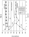
- FIG. 8 show results of multiple iterations of an exemplary laser operating wavelength control and stabilization method from FIG. 7 at different output powers for the laser.
- FIG. 1 A typical operating environment for practicing the present invention is shown in a simplified block diagram in FIG. 1 .
- a laser 101 driven by a controllable injection current source 102 is monitored, measured, stabilized, and controlled to operate at a desired target operating wavelength and output power by a controller 103 .
- Controller 103 supplies appropriate control signals both to the controllable current source 102 that supplies the laser injection current on lead 104 and to the controllable current source 108 coupled to the thermoelectric element 107 on lead 105 for adjusting the laser temperature.
- the laser assembly is understood to include laser 101 , the controllable current sources 102 and 108 , and the controllable thermoelectric element 107 coupled to the laser 101 .
- Controllable thermoelectric elements such as a Peltier element, which is well known in the art, can be utilized to provide a controlled temperature to the laser 101 .
- Controllable current source 108 coupled to controllable thermoelectric element 107 receives control signals from controller 103 via lead 105 to increase or decrease the laser temperature.
- Leads 106 and 109 are shown in FIG. 1 to denote the availability of laser operating parameters from the laser for the controller 103 .
- the parameters to be utilized by the controller include the output power (P), the temperature (T), the operating wavelength ( ⁇ c ), and the injection current (I). In FIG. 1 , only the power and temperature are shown. These parameters can be monitored and measured in a variety of well known ways by controller 103 or by specific monitoring devices and circuitry coupled to the laser.
- back face monitoring of a semiconductor laser can provide access to the output power and indirectly to the laser operating wavelength
- the actual temperature of the laser can be measured from the controllable thermoelectric heating element by a thermistor or the like via lead 109
- the actual temperature of the laser can alternatively be measured from the control signals applied on lead 105
- the injection current can be measured from the current source via lead 104 . It is expected that the operating wavelength is to be determined using the techniques of the present invention described below.
- Controller 103 can be realized as a hardware, firmware or software control device.
- a digital signal processor (DSP) or application specific integrated circuit (ASIC) can be employed for this purpose.
- the controller is capable of information processing and includes at least one internal or external storage medium for storing initial and measured parameters that are required for the operation of the device according to the present invention.
- the controller is initialized or initially programmed with certain desired or target values that are used according to the principles of the invention to achieve the appropriate amount of wavelength stabilization and control.
- the initial values that are contemplated being used by the controller are depicted in FIG.
- ⁇ a threshold value ( ⁇ ), the target operating wavelength ( ⁇ 0 ), the desired output power (P out ), an initial temperature (T 0 ), the relative efficiency ( ⁇ rel ), and the change in temperature versus the change in relative efficiency ( ⁇ T/ ⁇ rel ).
- output power and operating wavelength are among the most important static parameters characterizing laser performance.
- the operating wavelength of a laser such as a semiconductor laser is well understood to be dependent upon the laser chip temperature and carrier density in the gain medium or active region of the laser.
- the operating wavelength of the laser will undergo a shift. This wavelength shift can be caused by aging of the laser wherein it is necessary over time to increase the injection current to maintain a desired output power. It can also be caused by a need for increased or decreased output power from the laser which can be achieved by a corresponding change in the injection current to the laser.
- the present invention is directed to a method for measuring and monitoring certain operating parameters in step 201 in order to characterize the laser (e.g., the relative injection current efficiency of the laser) and then for controlling and/or stabilizing the operating wavelength of the laser in step 202 via the characterization and further parameter observations in order to obtain a target operating wavelength at a desired output power level.
- This method advantageously controls the operating wavelength from the beginning of life for the device until its end of life at all levels of output power.
- operating wavelength is understood to mean a particular wavelength at which the laser is classified as operating such as the center emission wavelength, that is, a wavelength central to the band of wavelengths emitted by a laser in operation, regardless of whether the laser operates as a single mode or multimode laser. Given that some classes of lasers lack the stability to maintain a truly single mode output at a consistent wavelength, the term is also understood to encompass a small band of wavelengths about a nominal central wavelength.
- Relative injection current efficiency or relative efficiency of the laser, ⁇ rel is defined as the ratio of two measured injection currents.
- the first reference current in the numerator of the ratio is denoted I 0 and is measured as a function of the output power of the laser P out at an arbitrary reference temperature T 0 and at a reference time t 0 .
- the second reference current in the denominator of the ratio is denoted as I and is measured as a function of the laser temperature T and the time t at the same output power of the laser P out and at the target operating wavelength ⁇ 0 .
- the relative efficiency of the laser is expressed as follows:
- Wavelength control can therefore be accomplished by understanding the relationship between the laser temperature and the output power at the target operating wavelength.
- FIG. 3 One exemplary method for measuring the parameters and characterizing the laser operations via the functions described above is shown in the flowchart depicted in FIG. 3 .
- the method is particularly well suited to semiconductor lasers, but it can be extended to other types of lasers as well.
- Step 1 is comprised of operational blocks 301 and 302 .
- the purpose of step 1 is to characterize the laser injection current I 0 (shown as the numerator of ⁇ rel function) as a function of the output power P out for a constant reference temperature T 0 of the laser.
- the reference temperature is selected to be in the middle of a specified operating range for the laser chip temperature. For this portion of the characterization process, it is expected that the operating wavelength ⁇ c of the laser will vary as the output power is changed.
- the data points can be fit or approximated using a particular function or curve.
- a linear function can be used for the curve fitting of the data points as shown in FIG. 4 , where intermediate points between the measured data points are determined using linear interpolation techniques.
- Step 2 of the characterization portion of the method includes operational blocks 303 and 304 .
- the purpose of step 2 is to characterize the injection current I (denominator of ⁇ rel function) and the corresponding laser temperature T as a function of output power P out for the laser while maintaining the operating wavelength of the laser ( ⁇ c ) constant at the target wavelength ⁇ 0 . It is expected that the temperature of the laser will also have to be adjusted as the output power is changed in order to maintain a constant wavelength for the laser.
- the injection current I and the corresponding laser temperature T are measured as the output power is varied over the range of interest while maintaining the laser operating wavelength constant at a desired target operating wavelength ⁇ 0 .
- the injection current I and the corresponding laser temperature T are characterized in mathematical terms such as in a formulaic representation similar to the representation shown above in step 1 .
- Step 3 of the characterization portion of the method includes operational block 305 .
- the relative efficiency of the laser ⁇ rel is computed as a function of the output power by calculating the ratio of the injection current I 0 found in step 1 and the injection current I found in step 2 . That is, ⁇ rel is equal to the ratio I 0 /I as depicted above in Eq. 1.
- the corresponding laser temperature T as a function of the output power is shown in the same plot.
- ⁇ rel 1.2 ⁇ 10 ⁇ 3 ⁇ P out +0.904, and (3) T ⁇ 0.1749 ⁇ P out +43.038. (4) where the output power P out , is expressed in milliwatts (mW) and the temperature T is in degrees Celsius (° C.).
- Step 4 of the characterization portion of the method includes operational block 306 .
- the purpose of step 4 is to determine the change in laser temperature ⁇ T versus the change in relative efficiency ⁇ rel .
- ⁇ const .
- the change of relative efficiency versus temperature change results in ⁇ T/ ⁇ rel ⁇ 147.8° C.
- This relation also may be determined directly from FIG. 6 .
- the temperature T of the data points determined in Step 3 for a constant wavelength is plotted as a function of the relative efficiency ⁇ rel .
- the characterization information is stored in the associated storage of the controller as shown in operational block 307 .
- the information collected during the laser characterization is stored in a medium such as random access memory or EEPROM or the like associated with and available to the controller. With this information from the characterization process available to the controller, it is possible to stabilize and control the wavelength of the laser to a desired target wavelength for a particular output power in a range of output powers. The control process is described below and depicted in the flowchart shown in FIG. 7 .
- the laser is operated at a target output power P out within the laser specifications as shown in step 700 .
- the output power monitor signal returned via lead 106 is maintained at a substantially constant value by controlling, via lead 104 , the injection current from source 102 using steps 701 – 704 for laser output power control.
- step 701 the laser output power P out is measured.
- the injection current from source 102 is then adjusted in step 702 .
- the laser output power P out is again measured in step 703 .
- step 704 the output power is compared with the target output power for the laser to determine whether the difference or the absolute value of the difference (as shown in FIG. 7 ) between the two power values is less than a power threshold ⁇ p .
- control is returned to step 702 ; when the difference of the two powers is less than or equal to the threshold, the method proceeds to step 705 .
- step 705 the injection current I is also measured at an arbitrary temperature T and at an arbitrary time t.
- the target relative efficiency ⁇ rel,target together with the measured relative efficiency in step 708 , it is possible to compute the relative efficiency difference ⁇ rel,target ⁇ rel,meas for the particular output power P out .
- the threshold value ⁇ is a relatively small number.
- the threshold value employed has been on the order of ⁇ 2 nm for Raman pump lasers operating in a co-propagating mode (e.g., multi-mode Fabry-Perot lasers) or ⁇ 0.1 nm for WDM signal lasers (e.g., single-mode DFB lasers).
- the process control is transferred to step 712 because the laser parameters are at the desired operating points. If the comparison shown that the relative efficiency is greater than or equal to the threshold, then the method proceeds to step 710 for further adjustments.
- the injection current is adjusted to achieve operation at the desired output power level. In order to avoid laser temperature fluctuation, it may be desirable to apply only a portion of ⁇ T to make the change in laser temperature.
- control for the method is returned back to step 701 .
- This process is iterated until both output power and relative efficiency are in the desired range. Once the desired operating values are achieved, these values are checked on a regular basis in order to compensate for environmental changes or aging effects. Since these effects cause relatively slow changes in the operating parameters, iterations can occur on the order of every few minutes. Also, as shown in step 712 , the control loop will be restarted at step 700 when the laser is being adjusted to operate at a new target output power P 0 . Otherwise, the process repeats the monitoring at step 701 .
- the characterization and control technique is applied to a multi-mode Fabry-Perot semiconductor laser being used for Raman co-pumping (that is, the pump and transmission signals are co-propagating in the system) with the results of the wavelength stabilization shown in FIG. 8 .
- the target operating wavelength of the laser is set to 1499 nm and the output power is varied over the range from 17 mW to 85 mW (i.e., 5 ⁇ 17 mW).
- Line 801 depicts the convergence of the laser operating wavelength to the target for an output power of 17 mW; line 802 depicts the convergence of the laser operating wavelength to the target for an output power of 34 mW; line 803 depicts the convergence of the laser operating wavelength to the target for an output power of 51 mW; line 804 depicts the convergence of the laser operating wavelength to the target for an output power of 68 mW; and line 805 depicts the convergence of the laser operating wavelength to the target for an output power of 85 mW.
- the results shown in FIG. 8 exhibit a stabilization of the operating wavelength to a range within ⁇ 2 nm. The procedure converges rapidly and in a well-behaved manner independent of the output power level.
- a laser exhibits a relatively broad tuning range suitable for DWDM or WDM applications or some other application that requires wavelength tuning, a family of these characterization curves will be created for different target operating wavelengths. Then the corresponding control parameters are retrieved from storage to sweep the laser to its new operating wavelength.
Landscapes
- Physics & Mathematics (AREA)
- Condensed Matter Physics & Semiconductors (AREA)
- General Physics & Mathematics (AREA)
- Electromagnetism (AREA)
- Optics & Photonics (AREA)
- Semiconductor Lasers (AREA)
Abstract
Description
-
- Pout=laser output power;
- P0=target laser output power;
- I=laser injection current;
- I0=reference laser injection current;
- λc=laser wavelength;
- λ0=target wavelength;
- ηrel=relative efficiency;
- Δηrel=relative efficiency change;
- ΔT=temperature change;
- ε=wavelength adjustment threshold value;
- t=time; and
- t0=reference time.
where λc is the operating or center emission wavelength of the laser.
I 0=5.26×P out+21.84, (2)
where the injection current I0 is expressed in milliamps (mA) and the output power Pout is expressed in milliwatts (mW) and wherein the reference temperature is T0=28.2° C. As is apparent to those persons skilled in the art, more complex curve fitting techniques or analysis tools or even more observed data points can be used to compute functions that fit the data points even more accurately. It is contemplated that the accuracy of the analysis can be even further improved by fitting the computed function in a manner that the wavelength deviation from the target wavelength is minimized.
ηrel=1.2×10⁻³ ×P out+0.904, and (3)
T×−0.1749×P out+43.038. (4)
where the output power Pout, is expressed in milliwatts (mW) and the temperature T is in degrees Celsius (° C.).
(ΔT/Δη rel)=(ΔT/ΔP)/(ΔP/Δη rel)|λ=const. (5)
Using Eqs. 3 and 4, the change of relative efficiency versus temperature change results in ΔT/Δηrel≈−147.8° C. This relation also may be determined directly from
Claims (4)
Priority Applications (1)
| Application Number | Priority Date | Filing Date | Title |
|---|---|---|---|
| US11/058,331 US7242701B2 (en) | 2005-02-15 | 2005-02-15 | Laser wavelength control arrangement and method |
Applications Claiming Priority (1)
| Application Number | Priority Date | Filing Date | Title |
|---|---|---|---|
| US11/058,331 US7242701B2 (en) | 2005-02-15 | 2005-02-15 | Laser wavelength control arrangement and method |
Publications (2)
| Publication Number | Publication Date |
|---|---|
| US20060182157A1 US20060182157A1 (en) | 2006-08-17 |
| US7242701B2 true US7242701B2 (en) | 2007-07-10 |
Family
ID=36815564
Family Applications (1)
| Application Number | Title | Priority Date | Filing Date |
|---|---|---|---|
| US11/058,331 Expired - Fee Related US7242701B2 (en) | 2005-02-15 | 2005-02-15 | Laser wavelength control arrangement and method |
Country Status (1)
| Country | Link |
|---|---|
| US (1) | US7242701B2 (en) |
Families Citing this family (8)
| Publication number | Priority date | Publication date | Assignee | Title |
|---|---|---|---|---|
| JP4800050B2 (en) * | 2006-01-31 | 2011-10-26 | 本田技研工業株式会社 | Fuel cell vehicle fuel consumption display device and fuel cell vehicle fuel consumption display method |
| US20120146452A1 (en) * | 2010-12-10 | 2012-06-14 | Miradia, Inc. | Microelectromechanical system device and semi-manufacture and manufacturing method thereof |
| EP2735064A2 (en) * | 2011-07-22 | 2014-05-28 | Insight Photonic Solutions, Inc. | System and method of dynamic and adaptive creation of a wavelength-continuous and prescribed wavelength versus time sweep from a laser |
| EP2812960A4 (en) | 2012-02-10 | 2015-10-28 | Nkt Photonics As | Laser device with frequency stabilising control module |
| JP7165144B2 (en) * | 2017-12-15 | 2022-11-02 | 株式会社堀場製作所 | Semiconductor laser device, driving method and driving program for semiconductor laser device |
| JP7118141B2 (en) * | 2018-05-09 | 2022-08-15 | 三菱電機株式会社 | Optical transmission module adjustment inspection system, optical transmission module adjustment inspection method, and optical transmission module manufacturing method |
| CN110999072B (en) * | 2019-04-25 | 2024-03-22 | 深圳市汇顶科技股份有限公司 | Post-compensation for thermal drift of crystal oscillators |
| CN112710296B (en) * | 2020-12-15 | 2022-10-21 | 株洲菲斯罗克光电科技股份有限公司 | Method and system for improving stability of output wavelength of laser by optical fiber gyroscope |
Citations (5)
| Publication number | Priority date | Publication date | Assignee | Title |
|---|---|---|---|---|
| US4608697A (en) | 1983-04-11 | 1986-08-26 | At&T Bell Laboratories | Spectral control arrangement for coupled cavity laser |
| US5220578A (en) | 1991-11-01 | 1993-06-15 | At&T Bell Laboratories | Long term mode stabilization for distributed bragg reflector laser |
| US6292497B1 (en) * | 1997-10-28 | 2001-09-18 | Nec Corporation | Laser diode driving method and circuit |
| US6516010B1 (en) * | 1999-07-13 | 2003-02-04 | Agere Systems, Inc. | Method and apparatus for active numeric temperature compensation of an etalon in a wavelength stabilized laser |
| US6570900B2 (en) * | 1993-07-28 | 2003-05-27 | Cynosure, Inc. | Method and apparatus for replenishing dye solution in a dye laser |
-
2005
- 2005-02-15 US US11/058,331 patent/US7242701B2/en not_active Expired - Fee Related
Patent Citations (5)
| Publication number | Priority date | Publication date | Assignee | Title |
|---|---|---|---|---|
| US4608697A (en) | 1983-04-11 | 1986-08-26 | At&T Bell Laboratories | Spectral control arrangement for coupled cavity laser |
| US5220578A (en) | 1991-11-01 | 1993-06-15 | At&T Bell Laboratories | Long term mode stabilization for distributed bragg reflector laser |
| US6570900B2 (en) * | 1993-07-28 | 2003-05-27 | Cynosure, Inc. | Method and apparatus for replenishing dye solution in a dye laser |
| US6292497B1 (en) * | 1997-10-28 | 2001-09-18 | Nec Corporation | Laser diode driving method and circuit |
| US6516010B1 (en) * | 1999-07-13 | 2003-02-04 | Agere Systems, Inc. | Method and apparatus for active numeric temperature compensation of an etalon in a wavelength stabilized laser |
Also Published As
| Publication number | Publication date |
|---|---|
| US20060182157A1 (en) | 2006-08-17 |
Similar Documents
| Publication | Publication Date | Title |
|---|---|---|
| US7242701B2 (en) | Laser wavelength control arrangement and method | |
| US6928092B2 (en) | Method and apparatus for active numeric temperature compensation of an etalon in a wavelength stabilized laser | |
| US6400737B1 (en) | Automatic closed-looped gain adjustment for a temperature tuned, wavelength stabilized laser source in a closed-loop feedback control system | |
| US5594748A (en) | Method and apparatus for predicting semiconductor laser failure | |
| US6788719B2 (en) | Open loop control of SGDBR lasers | |
| EP1564915B1 (en) | Low relative intensity noise fiber grating type laser diode | |
| US6690693B1 (en) | Power and wavelength control of sampled grating distributed Bragg reflector lasers | |
| US20070258494A1 (en) | Wavelength Control of Laser Light | |
| EP2058907B1 (en) | Frequency-stabilized laser device, laser frequency stabilizing method, and laser frequency stabilizing program | |
| US8953650B2 (en) | Method to control emission wavelength of tunable laser diode | |
| EP1571743A1 (en) | Method and apparatus for wavelength stabilization of a laser by means of temperature compensation. | |
| EP0979547B1 (en) | Tunable external cavity diode laser | |
| EP1109276A2 (en) | Method and apparatus for stabilizing laser wavelength | |
| US6954476B2 (en) | Sampled grating distributed Bragg reflector laser controller | |
| US8170074B2 (en) | Tracking injection seeding power based on back facet monitoring (BFM) of an injection seeded laser | |
| US6839364B1 (en) | Feedback control loop operating system for tunable source | |
| US20050100065A1 (en) | Controller calibration for small form factor sampled grating distributed bragg reflector laser | |
| US6518563B1 (en) | Detecting aging of optical components | |
| US20030123133A1 (en) | Distributed raman amplifier module auto-setup | |
| US7869717B2 (en) | Optical communication light source unit and wavelength monitoring control method | |
| US7110167B2 (en) | System and method for dynamic range extension and stable low power operation of optical amplifiers using pump laser pulse modulation | |
| US6785309B2 (en) | Method for frequency and mode stabilisation of a tuneable laser that has at least three sections | |
| US6690689B2 (en) | Apparatus and method for compensating for age induced wavelength drift in tunable semiconductor lasers | |
| JP2001217502A (en) | Method for controlling laser system during channel selection operation | |
| CN111628408A (en) | Frequency stabilization system of semiconductor laser |
Legal Events
| Date | Code | Title | Description |
|---|---|---|---|
| AS | Assignment |
Owner name: LUCENT TECHNOLOGIES INC., NEW JERSEY Free format text: ASSIGNMENT OF ASSIGNORS INTEREST;ASSIGNORS:BOLLENZ, BERND;CZOTSCHER, KONRAD;WERNER, DIETER;REEL/FRAME:016287/0145 Effective date: 20050215 |
|
| STCF | Information on status: patent grant |
Free format text: PATENTED CASE |
|
| FPAY | Fee payment |
Year of fee payment: 4 |
|
| FPAY | Fee payment |
Year of fee payment: 8 |
|
| AS | Assignment |
Owner name: OMEGA CREDIT OPPORTUNITIES MASTER FUND, LP, NEW YORK Free format text: SECURITY INTEREST;ASSIGNOR:WSOU INVESTMENTS, LLC;REEL/FRAME:043966/0574 Effective date: 20170822 Owner name: OMEGA CREDIT OPPORTUNITIES MASTER FUND, LP, NEW YO Free format text: SECURITY INTEREST;ASSIGNOR:WSOU INVESTMENTS, LLC;REEL/FRAME:043966/0574 Effective date: 20170822 |
|
| AS | Assignment |
Owner name: WSOU INVESTMENTS, LLC, CALIFORNIA Free format text: ASSIGNMENT OF ASSIGNORS INTEREST;ASSIGNOR:ALCATEL LUCENT;REEL/FRAME:044000/0053 Effective date: 20170722 |
|
| FEPP | Fee payment procedure |
Free format text: MAINTENANCE FEE REMINDER MAILED (ORIGINAL EVENT CODE: REM.); ENTITY STATUS OF PATENT OWNER: LARGE ENTITY |
|
| AS | Assignment |
Owner name: BP FUNDING TRUST, SERIES SPL-VI, NEW YORK Free format text: SECURITY INTEREST;ASSIGNOR:WSOU INVESTMENTS, LLC;REEL/FRAME:049235/0068 Effective date: 20190516 |
|
| AS | Assignment |
Owner name: WSOU INVESTMENTS, LLC, CALIFORNIA Free format text: RELEASE BY SECURED PARTY;ASSIGNOR:OCO OPPORTUNITIES MASTER FUND, L.P. (F/K/A OMEGA CREDIT OPPORTUNITIES MASTER FUND LP;REEL/FRAME:049246/0405 Effective date: 20190516 |
|
| LAPS | Lapse for failure to pay maintenance fees |
Free format text: PATENT EXPIRED FOR FAILURE TO PAY MAINTENANCE FEES (ORIGINAL EVENT CODE: EXP.); ENTITY STATUS OF PATENT OWNER: LARGE ENTITY |
|
| STCH | Information on status: patent discontinuation |
Free format text: PATENT EXPIRED DUE TO NONPAYMENT OF MAINTENANCE FEES UNDER 37 CFR 1.362 |
|
| FP | Lapsed due to failure to pay maintenance fee |
Effective date: 20190710 |
|
| AS | Assignment |
Owner name: OT WSOU TERRIER HOLDINGS, LLC, CALIFORNIA Free format text: SECURITY INTEREST;ASSIGNOR:WSOU INVESTMENTS, LLC;REEL/FRAME:056990/0081 Effective date: 20210528 |
|
| AS | Assignment |
Owner name: WSOU INVESTMENTS, LLC, CALIFORNIA Free format text: RELEASE BY SECURED PARTY;ASSIGNOR:TERRIER SSC, LLC;REEL/FRAME:056526/0093 Effective date: 20210528 |