US7239281B2 - Fin-shaped antenna apparatus for vehicle radio application - Google Patents
Fin-shaped antenna apparatus for vehicle radio application Download PDFInfo
- Publication number
- US7239281B2 US7239281B2 US11/099,509 US9950905A US7239281B2 US 7239281 B2 US7239281 B2 US 7239281B2 US 9950905 A US9950905 A US 9950905A US 7239281 B2 US7239281 B2 US 7239281B2
- Authority
- US
- United States
- Prior art keywords
- fin
- antenna
- shaped
- antenna apparatus
- circuit
- Prior art date
- Legal status (The legal status is an assumption and is not a legal conclusion. Google has not performed a legal analysis and makes no representation as to the accuracy of the status listed.)
- Expired - Fee Related
Links
Images


Classifications
-
- H—ELECTRICITY
- H01—ELECTRIC ELEMENTS
- H01Q—ANTENNAS, i.e. RADIO AERIALS
- H01Q1/00—Details of, or arrangements associated with, antennas
- H01Q1/27—Adaptation for use in or on movable bodies
- H01Q1/32—Adaptation for use in or on road or rail vehicles
- H01Q1/325—Adaptation for use in or on road or rail vehicles characterised by the location of the antenna on the vehicle
- H01Q1/3275—Adaptation for use in or on road or rail vehicles characterised by the location of the antenna on the vehicle mounted on a horizontal surface of the vehicle, e.g. on roof, hood, trunk
-
- H—ELECTRICITY
- H01—ELECTRIC ELEMENTS
- H01Q—ANTENNAS, i.e. RADIO AERIALS
- H01Q1/00—Details of, or arrangements associated with, antennas
- H01Q1/40—Radiating elements coated with or embedded in protective material
- H01Q1/405—Radome integrated radiating elements
-
- H—ELECTRICITY
- H01—ELECTRIC ELEMENTS
- H01Q—ANTENNAS, i.e. RADIO AERIALS
- H01Q11/00—Electrically-long antennas having dimensions more than twice the shortest operating wavelength and consisting of conductive active radiating elements
- H01Q11/02—Non-resonant antennas, e.g. travelling-wave antenna
- H01Q11/08—Helical antennas
-
- H—ELECTRICITY
- H01—ELECTRIC ELEMENTS
- H01Q—ANTENNAS, i.e. RADIO AERIALS
- H01Q7/00—Loop antennas with a substantially uniform current distribution around the loop and having a directional radiation pattern in a plane perpendicular to the plane of the loop
Definitions
- the present invention relates to a fin-shaped antenna apparatus for vehicle radio application, and more particularly to fin-shaped antenna apparatus with enhanced AM/FM radio reception and arranged on vehicle top casing.
- the wireless electronic products generally comprise antenna designed for particular frequency, directive and radio strength.
- the conventional antenna is made into rod shape with length corresponding to the quarter wavelength of the radio wave used.
- the vehicle antenna is a telescopic rod for both AM and FM reception.
- the vehicle antenna might have the problem of retraction after long time use, which is troublesome for user.
- a helix antenna made of spiral metal wire is developed.
- the reception quality of the helix antenna is not satisfactory.
- a glass antenna is developed wherein flexible conductive material is coated on vehicle glass to function as AM-FM dual antenna.
- the flexible conductive material is expensive.
- a printed circuit board with special-shaped planar antenna is also developed.
- the signal reception quality is poor when the planar antenna is assembled to metal vehicle casing due to the signal absorption by metal casing.
- the present invention provides a fin-shaped antenna apparatus for vehicle radio application, which can be assembled atop the vehicle for aesthetic effect and can enhance AM/FM radio reception quality.
- the fin-shaped antenna apparatus for vehicle ratio application is electrically connected to a wireless receiver circuit and receives a radio signal.
- the fin-shaped antenna apparatus includes an AM antenna comprising magnetic core with winding thereon, a signal amplifier circuit board, an FM resonance circuit on the signal amplifier circuit board.
- the AM antenna is separated with the FM resonance circuit.
- the FM resonance circuit comprises a plurality of inductors to form a resonance circuit, which is connected to a metal base for enhancing the reception thereof. Therefore, the signal quality for vehicle radio application is enhanced.
- FIG. 1 shows a perspective view of the fin-shaped antenna for vehicle radio according to the present invention
- FIG. 2 is an exploded view of the fin-shaped antenna for vehicle radio according to the present invention.
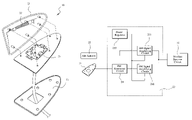
- FIG. 3 shows the block diagram of the present invention
- FIG. 4 shows the circuit diagram of the present invention
- FIG. 5 shows the radiation characteristic of antenna gain for the fin-shaped antenna apparatus in vertical plane
- FIG. 6 shows the radiation characteristic of antenna gain for the fin-shaped antenna apparatus in horizontal plane
- FIG. 7 shows the frequency response for the fin-shaped antenna apparatus according to the present invention.
- FIG. 1 shows a perspective view of the fin-shaped antenna for vehicle radio according to the present invention.
- FIG. 2 is an exploded view of the fin-shaped antenna for vehicle radio according to the present invention.
- the fin-shaped antenna is used to receive broadcast signal of radio station before the processing of a wireless receiver circuit of the vehicle radio.
- the fin-shaped antenna has shape like fish fin and can be arranged on vehicle casing.
- the fin-shaped antenna has aesthetic shape with better signal reception than conventional telescopic antenna or glass antenna.
- the fin-shaped antenna apparatus 20 comprises a fin-shaped cover 21 , an AM antenna 22 with magnetic core and winding, a signal amplifier circuit board 23 , an FM resonance circuit 24 on the signal amplifier circuit board 23 and a metal base 25 .
- FIGS. 3 and 4 show the block diagram and circuit diagram of the present invention.
- the fin-shaped antenna 20 is connected to an antenna signal input of a wireless receiver circuit 51 .
- the AM antenna 22 is arranged on inner side of the fin-shaped cover 21 and arranged on topside of the fin-shaped inner space of the fin-shaped antenna 20 .
- the signal amplifier circuit board 23 is arranged atop the metal base 25 and comprises an AM signal amplifying circuit 231 for the AM antenna 22 , an FM signal amplifying circuit 232 , and a power regulator 233 .
- the signal amplifier circuit board 23 is mounted with the FM resonance circuit 24 thereon.
- the FM resonance circuit 24 is composed of a plurality of inductors to form FM resonance circuit with the FM signal amplifying circuit 232 .
- the FM resonance circuit 24 provides impedance match with the wireless receiver circuit 51 in the radio band of interest. Therefore, the present invention has better FM reception than conventional FM receiver circuit.
- the AM antenna is separated with the FM antenna in the present invention; different from a sharing AM-FM antenna in prior art vehicle radio.
- the AM antenna 22 is an unbalanced circuit and the FM antenna 24 is a balanced circuit.
- the power regulator 233 is powered by a vehicle power and provides a stable electrical power to the AM signal amplifying circuit 231 and the FM signal amplifying circuit 232 .
- the metal base 25 on bottom of the fin-shaped antenna apparatus 20 not only fixes the fin-shaped antenna apparatus 20 to vehicle top casing, but also enhances the signal reception for FM antenna when the metal base 25 is connected to the FM antenna. Moreover, the fin-shaped antenna apparatus 20 has excellent impedance match with the wireless receiver circuit 51 . In the shown preferred embodiment of the present invention, the impedance is about 50 Ohm.
- the fin-shaped antenna apparatus 20 has compact size and is suitable for arranging on vehicle top casing.
- the fin-shaped cover 21 encloses the AM antenna 22 and the signal amplifier circuit board 23 . Therefore, the fin-shaped cover 21 provides protection for circuit inside and aesthetic effect for overall appearance.
- FIG. 5 shows the radiation characteristic of antenna gain for the fin-shaped antenna apparatus 20 according to the present invention in vertical plane.
- FIG. 6 shows the radiation characteristic of antenna gain for the fin-shaped antenna apparatus 20 according to the present invention in horizontal plane.
- the antenna gain for the fin-shaped antenna apparatus 20 according to the present is about 0–3 dBi.
- FIG. 7 shows the frequency response for the fin-shaped antenna apparatus 20 according to the present invention, wherein the frequency range is between 30 KHz to 300 MHz.
- the impedance is matched with 50 Ohm for those frequency bands and suitable for radio application.
Landscapes
- Engineering & Computer Science (AREA)
- Remote Sensing (AREA)
- Details Of Aerials (AREA)
- Support Of Aerials (AREA)
Abstract
Description
Claims (7)
Priority Applications (1)
| Application Number | Priority Date | Filing Date | Title |
|---|---|---|---|
| US11/099,509 US7239281B2 (en) | 2005-04-06 | 2005-04-06 | Fin-shaped antenna apparatus for vehicle radio application |
Applications Claiming Priority (1)
| Application Number | Priority Date | Filing Date | Title |
|---|---|---|---|
| US11/099,509 US7239281B2 (en) | 2005-04-06 | 2005-04-06 | Fin-shaped antenna apparatus for vehicle radio application |
Publications (2)
| Publication Number | Publication Date |
|---|---|
| US20060227057A1 US20060227057A1 (en) | 2006-10-12 |
| US7239281B2 true US7239281B2 (en) | 2007-07-03 |
Family
ID=37082709
Family Applications (1)
| Application Number | Title | Priority Date | Filing Date |
|---|---|---|---|
| US11/099,509 Expired - Fee Related US7239281B2 (en) | 2005-04-06 | 2005-04-06 | Fin-shaped antenna apparatus for vehicle radio application |
Country Status (1)
| Country | Link |
|---|---|
| US (1) | US7239281B2 (en) |
Cited By (16)
| Publication number | Priority date | Publication date | Assignee | Title |
|---|---|---|---|---|
| WO2009065806A1 (en) * | 2007-11-20 | 2009-05-28 | Continental Automotive Gmbh | Fin-shaped multiband antenna module for vehicles |
| WO2010036435A1 (en) * | 2008-09-24 | 2010-04-01 | Laird Technologies, Inc. | Interchangeable slidably mountable fins for antenna assemblies |
| US20100265145A1 (en) * | 2009-04-17 | 2010-10-21 | Hyundai Motor Company | Integrated antenna system for car and method of making same |
| DE102009038150A1 (en) | 2009-08-20 | 2011-03-03 | Continental Automotive Gmbh | Multi-band antenna module for a vehicle, comprises multiple antenna units, which includes receiving antennas and radio antennas |
| US8519897B2 (en) | 2010-09-30 | 2013-08-27 | Laird Technologies, Inc. | Low-profile antenna assembly |
| US8537062B1 (en) | 2010-09-30 | 2013-09-17 | Laird Technologies, Inc. | Low-profile antenna assemblies |
| US9048547B2 (en) | 2010-12-30 | 2015-06-02 | Silicon Laboratories Inc. | Air loop antenna for shared AM/FM |
| US20150311582A1 (en) * | 2012-11-09 | 2015-10-29 | The University Of Birmingham | Reconfigurable mimo antenna for vehicles |
| US20150325906A1 (en) * | 2014-05-08 | 2015-11-12 | KATHREIN Automotive GmbH & Co. KG | Roof-mounted antenna arrangement |
| CN105789834A (en) * | 2016-03-14 | 2016-07-20 | 无锡南理工科技发展有限公司 | Radio signal receiving antenna for vehicle and ship |
| US9496624B2 (en) * | 2015-03-24 | 2016-11-15 | Auden Techno Corp. | Antenna device and antenna apparatus |
| EP3147999A1 (en) | 2015-09-25 | 2017-03-29 | Taoglas Group Holdings | Fin-type antenna assemblies |
| EP3147997A1 (en) | 2015-09-25 | 2017-03-29 | Taoglas Group Holdings | Fin-type antenna assemblies |
| USD794615S1 (en) | 2015-09-25 | 2017-08-15 | Taoglas Group Holdings | Single fin antenna |
| USD803196S1 (en) | 2015-09-25 | 2017-11-21 | Taoglas Group Holdings Limited | Dual fin antenna |
| US10211539B2 (en) | 2012-07-31 | 2019-02-19 | Smart Antenna Technologies Ltd. | Reconfigurable antenna |
Families Citing this family (12)
| Publication number | Priority date | Publication date | Assignee | Title |
|---|---|---|---|---|
| US8081126B2 (en) * | 2006-11-22 | 2011-12-20 | Nippon Antena Kabushiki Kaisha | Antenna apparatus |
| US20080117111A1 (en) * | 2006-11-22 | 2008-05-22 | Nippon Antena Kabushiki Kaisha | Antenna Apparatus |
| CN201008020Y (en) * | 2007-01-23 | 2008-01-16 | 蒋小平 | Shark fin type antenna |
| CN101000977B (en) * | 2007-01-23 | 2012-05-23 | 蒋小平 | Shark fin type antenna |
| GB2490119B (en) * | 2011-04-18 | 2015-10-21 | Signplay Ltd | Lamp with communications antenna and light level sensor |
| CN102646863B (en) * | 2012-04-28 | 2014-02-26 | 中电科技扬州宝军电子有限公司 | Guiding high-strength dual-waveband directional antenna |
| USD748611S1 (en) * | 2013-12-24 | 2016-02-02 | Faltec Co., Ltd. | Antenna for a vehicle |
| JP2015139211A (en) * | 2014-01-24 | 2015-07-30 | 株式会社フジクラ | On-vehicle antenna device |
| US9941579B2 (en) * | 2015-06-04 | 2018-04-10 | Armstrong Aerospace, Inc. | Equipment mounting device |
| USD926164S1 (en) * | 2018-04-04 | 2021-07-27 | Taoglas Group Holdings Limited | Vehicle antenna |
| USD881857S1 (en) * | 2018-04-17 | 2020-04-21 | Furrion Property Holding Limited | Antenna base |
| USD912651S1 (en) * | 2019-05-24 | 2021-03-09 | Shenzhen Antop Technology Limited | Antenna base |
Citations (8)
| Publication number | Priority date | Publication date | Assignee | Title |
|---|---|---|---|---|
| US3939423A (en) * | 1974-07-01 | 1976-02-17 | Viktor Ivanovich Zakharov | Automobile active receiving antenna |
| US4001696A (en) * | 1974-08-02 | 1977-01-04 | George Louis Bannerman | Electronic antenna |
| US6078294A (en) * | 1996-03-01 | 2000-06-20 | Toyota Jidosha Kabushiki Kaisha | Antenna device for vehicles |
| US6380902B2 (en) * | 1998-09-23 | 2002-04-30 | Bernard Duroux | Vehicle exterior mirror with antenna |
| US6525693B2 (en) * | 2000-10-10 | 2003-02-25 | Fiat Auto S.P.A. | Device for the reception of GPS position signals |
| US6697024B2 (en) * | 2000-10-20 | 2004-02-24 | Donnelly Corporation | Exterior mirror with antenna |
| US6879294B2 (en) * | 2002-04-17 | 2005-04-12 | Alps Electric Co., Ltd. | Dual antenna capable of transmitting and receiving circularly polarized electromagnetic wave and linearly polarized electromagnetic wave |
| US20060038726A1 (en) * | 2002-10-15 | 2006-02-23 | Federico Iacovella | Vehicular antenna with improved screening |
-
2005
- 2005-04-06 US US11/099,509 patent/US7239281B2/en not_active Expired - Fee Related
Patent Citations (8)
| Publication number | Priority date | Publication date | Assignee | Title |
|---|---|---|---|---|
| US3939423A (en) * | 1974-07-01 | 1976-02-17 | Viktor Ivanovich Zakharov | Automobile active receiving antenna |
| US4001696A (en) * | 1974-08-02 | 1977-01-04 | George Louis Bannerman | Electronic antenna |
| US6078294A (en) * | 1996-03-01 | 2000-06-20 | Toyota Jidosha Kabushiki Kaisha | Antenna device for vehicles |
| US6380902B2 (en) * | 1998-09-23 | 2002-04-30 | Bernard Duroux | Vehicle exterior mirror with antenna |
| US6525693B2 (en) * | 2000-10-10 | 2003-02-25 | Fiat Auto S.P.A. | Device for the reception of GPS position signals |
| US6697024B2 (en) * | 2000-10-20 | 2004-02-24 | Donnelly Corporation | Exterior mirror with antenna |
| US6879294B2 (en) * | 2002-04-17 | 2005-04-12 | Alps Electric Co., Ltd. | Dual antenna capable of transmitting and receiving circularly polarized electromagnetic wave and linearly polarized electromagnetic wave |
| US20060038726A1 (en) * | 2002-10-15 | 2006-02-23 | Federico Iacovella | Vehicular antenna with improved screening |
Cited By (24)
| Publication number | Priority date | Publication date | Assignee | Title |
|---|---|---|---|---|
| US20100277379A1 (en) * | 2005-11-10 | 2010-11-04 | Laird Technologies, Inc. | Interchangeable slidably mountable fins for antenna assemblies |
| US8248315B2 (en) | 2005-11-10 | 2012-08-21 | Laird Technologies, Inc. | Interchangeable slidably mountable fins for antenna assemblies |
| WO2009065806A1 (en) * | 2007-11-20 | 2009-05-28 | Continental Automotive Gmbh | Fin-shaped multiband antenna module for vehicles |
| DE102007055323A1 (en) | 2007-11-20 | 2009-06-04 | Continental Automotive Gmbh | Finned multiband antenna module for vehicles |
| DE102007055323B4 (en) * | 2007-11-20 | 2013-04-11 | Continental Automotive Gmbh | Finned multiband antenna module for vehicles |
| WO2010036435A1 (en) * | 2008-09-24 | 2010-04-01 | Laird Technologies, Inc. | Interchangeable slidably mountable fins for antenna assemblies |
| US20100265145A1 (en) * | 2009-04-17 | 2010-10-21 | Hyundai Motor Company | Integrated antenna system for car and method of making same |
| DE102009038150A1 (en) | 2009-08-20 | 2011-03-03 | Continental Automotive Gmbh | Multi-band antenna module for a vehicle, comprises multiple antenna units, which includes receiving antennas and radio antennas |
| DE102009038150A8 (en) * | 2009-08-20 | 2011-06-01 | Continental Automotive Gmbh | Multiband antenna module for a vehicle |
| DE102009038150B4 (en) * | 2009-08-20 | 2013-11-07 | Continental Automotive Gmbh | Multiband antenna module for a vehicle |
| US8519897B2 (en) | 2010-09-30 | 2013-08-27 | Laird Technologies, Inc. | Low-profile antenna assembly |
| US8537062B1 (en) | 2010-09-30 | 2013-09-17 | Laird Technologies, Inc. | Low-profile antenna assemblies |
| US9048547B2 (en) | 2010-12-30 | 2015-06-02 | Silicon Laboratories Inc. | Air loop antenna for shared AM/FM |
| US10211539B2 (en) | 2012-07-31 | 2019-02-19 | Smart Antenna Technologies Ltd. | Reconfigurable antenna |
| US20150311582A1 (en) * | 2012-11-09 | 2015-10-29 | The University Of Birmingham | Reconfigurable mimo antenna for vehicles |
| US9825354B2 (en) * | 2012-11-09 | 2017-11-21 | Smart Antenna Technologies Ltd. | Reconfigurable MIMO antenna for vehicles |
| US20150325906A1 (en) * | 2014-05-08 | 2015-11-12 | KATHREIN Automotive GmbH & Co. KG | Roof-mounted antenna arrangement |
| US9653788B2 (en) * | 2014-05-08 | 2017-05-16 | KATHREIN Automotive GmbH & Co. KG | Roof-mounted antenna arrangement |
| US9496624B2 (en) * | 2015-03-24 | 2016-11-15 | Auden Techno Corp. | Antenna device and antenna apparatus |
| EP3147999A1 (en) | 2015-09-25 | 2017-03-29 | Taoglas Group Holdings | Fin-type antenna assemblies |
| EP3147997A1 (en) | 2015-09-25 | 2017-03-29 | Taoglas Group Holdings | Fin-type antenna assemblies |
| USD794615S1 (en) | 2015-09-25 | 2017-08-15 | Taoglas Group Holdings | Single fin antenna |
| USD803196S1 (en) | 2015-09-25 | 2017-11-21 | Taoglas Group Holdings Limited | Dual fin antenna |
| CN105789834A (en) * | 2016-03-14 | 2016-07-20 | 无锡南理工科技发展有限公司 | Radio signal receiving antenna for vehicle and ship |
Also Published As
| Publication number | Publication date |
|---|---|
| US20060227057A1 (en) | 2006-10-12 |
Similar Documents
| Publication | Publication Date | Title |
|---|---|---|
| US7239281B2 (en) | Fin-shaped antenna apparatus for vehicle radio application | |
| CN1330050C (en) | Internal antenna of mobile communication terminal | |
| EP2234209B1 (en) | Wireless terminal antenna | |
| US5541610A (en) | Antenna for a radio communication apparatus | |
| CN104681918B (en) | Bezel gap antennas | |
| US6417816B2 (en) | Dual band bowtie/meander antenna | |
| US7760146B2 (en) | Internal digital TV antennas for hand-held telecommunications device | |
| CN1126195C (en) | A radio communication device and an antenna system | |
| EP1750323A1 (en) | Multi-band antenna device for radio communication terminal and radio communication terminal comprising the multi-band antenna device | |
| US8681049B2 (en) | Built-in FM transmitting antenna applied to a mobile device | |
| WO1985002719A1 (en) | Dual band transceiver antenna | |
| CN102683861A (en) | Tunable loop antennas | |
| JP2003258523A (en) | Antenna system for wireless apparatus | |
| US7746278B2 (en) | Antenna arrangement | |
| KR20090096914A (en) | Planar type folded monopole antenna | |
| JP4875171B2 (en) | Multiband antenna | |
| US20090135075A1 (en) | Compact Multiband Antenna | |
| JP2010524324A (en) | Broadband antenna with double resonance | |
| US9774078B2 (en) | Antenna ground plane extension or antenna extension on lanyard | |
| JP2006310954A (en) | Shark fin antenna unit for car radio | |
| JP3112014U (en) | Fish radio antenna device for automobile radio | |
| US7113146B2 (en) | Broadband monopole | |
| KR200389379Y1 (en) | Fin-shaped antenna apparatus for vehicle radio application | |
| CN101242034B (en) | Small multi-frequency antenna | |
| CN113540763A (en) | Antenna and equipment |
Legal Events
| Date | Code | Title | Description |
|---|---|---|---|
| AS | Assignment |
Owner name: YEOUJYI ELECTRONICS CO., LTD., TAIWAN Free format text: ASSIGNMENT OF ASSIGNORS INTEREST;ASSIGNOR:LU, YU-SHENG;REEL/FRAME:016083/0545 Effective date: 20050328 Owner name: SKY YEAR INVESTMENTS LIMITED, JAPAN Free format text: ASSIGNMENT OF ASSIGNORS INTEREST;ASSIGNOR:LU, YU-SHENG;REEL/FRAME:016083/0545 Effective date: 20050328 |
|
| STCF | Information on status: patent grant |
Free format text: PATENTED CASE |
|
| FPAY | Fee payment |
Year of fee payment: 4 |
|
| FPAY | Fee payment |
Year of fee payment: 8 |
|
| FEPP | Fee payment procedure |
Free format text: MAINTENANCE FEE REMINDER MAILED (ORIGINAL EVENT CODE: REM.); ENTITY STATUS OF PATENT OWNER: SMALL ENTITY |
|
| LAPS | Lapse for failure to pay maintenance fees |
Free format text: PATENT EXPIRED FOR FAILURE TO PAY MAINTENANCE FEES (ORIGINAL EVENT CODE: EXP.); ENTITY STATUS OF PATENT OWNER: SMALL ENTITY |
|
| STCH | Information on status: patent discontinuation |
Free format text: PATENT EXPIRED DUE TO NONPAYMENT OF MAINTENANCE FEES UNDER 37 CFR 1.362 |
|
| FP | Lapsed due to failure to pay maintenance fee |
Effective date: 20190703 |