US720499A - Relief-valve arrangement for locomotive or other engines. - Google Patents
Relief-valve arrangement for locomotive or other engines. Download PDFInfo
- Publication number
- US720499A US720499A US1902126248A US720499A US 720499 A US720499 A US 720499A US 1902126248 A US1902126248 A US 1902126248A US 720499 A US720499 A US 720499A
- Authority
- US
- United States
- Prior art keywords
- valve
- relief
- water
- steam
- engine
- Prior art date
- Legal status (The legal status is an assumption and is not a legal conclusion. Google has not performed a legal analysis and makes no representation as to the accuracy of the status listed.)
- Expired - Lifetime
Links
Images


Classifications
-
- F—MECHANICAL ENGINEERING; LIGHTING; HEATING; WEAPONS; BLASTING
- F16—ENGINEERING ELEMENTS AND UNITS; GENERAL MEASURES FOR PRODUCING AND MAINTAINING EFFECTIVE FUNCTIONING OF MACHINES OR INSTALLATIONS; THERMAL INSULATION IN GENERAL
- F16K—VALVES; TAPS; COCKS; ACTUATING-FLOATS; DEVICES FOR VENTING OR AERATING
- F16K11/00—Multiple-way valves, e.g. mixing valves; Pipe fittings incorporating such valves
- F16K11/02—Multiple-way valves, e.g. mixing valves; Pipe fittings incorporating such valves with all movable sealing faces moving as one unit
- F16K11/06—Multiple-way valves, e.g. mixing valves; Pipe fittings incorporating such valves with all movable sealing faces moving as one unit comprising only sliding valves, i.e. sliding closure elements
- F16K11/078—Multiple-way valves, e.g. mixing valves; Pipe fittings incorporating such valves with all movable sealing faces moving as one unit comprising only sliding valves, i.e. sliding closure elements with pivoted and linearly movable closure members
- F16K11/0782—Single-lever operated mixing valves with closure members having flat sealing faces
- F16K11/0787—Single-lever operated mixing valves with closure members having flat sealing faces with both the supply and the discharge passages being on the same side of the closure members
-
- Y—GENERAL TAGGING OF NEW TECHNOLOGICAL DEVELOPMENTS; GENERAL TAGGING OF CROSS-SECTIONAL TECHNOLOGIES SPANNING OVER SEVERAL SECTIONS OF THE IPC; TECHNICAL SUBJECTS COVERED BY FORMER USPC CROSS-REFERENCE ART COLLECTIONS [XRACs] AND DIGESTS
- Y10—TECHNICAL SUBJECTS COVERED BY FORMER USPC
- Y10T—TECHNICAL SUBJECTS COVERED BY FORMER US CLASSIFICATION
- Y10T137/00—Fluid handling
- Y10T137/8593—Systems
- Y10T137/86493—Multi-way valve unit
- Y10T137/86815—Multiple inlet with single outlet
Definitions
- n NORRIS Fsrzns ca, Puoraurnu. WASHINGTON, n. c.
- n4 NOIINB Pnms co, r'mmmn'wo. WASHINGTON. o. c.
- This invention has reference to improvements in relief-valve arrangements for loco-' motive and other engines for enabling water of condensation to escape from either end of the engine cylinder or cylinders and, it may be, from the steam chest or chests of such engine when the same are fitted with piston or like steam-distributing valves, the object being to provide a valve arrangement for the purpose mentioned that will not be readily liable to become inoperative or unreliable in consequence of the presence therein of greasy matter.
- the invention consists for this purpose in a relief-valve arrangement
- a relief-valve arrangement comprising a casing formed with a valve-chamber and provided with a steam-inlet passage adapted to be directly or indirectly connected to the steam-boiler from which steam is supplied to the engine with which the valve arrangement is used, with one or more water-relief passages adapted to be connected through a suitable pipe or pipes to one or both ends of the engine cylinder or cylinders and, it may be, to the steam chest or chests of the engine, and a water outlet passage terminating at its outer end in the external atmosphere, the inner ends of the said passages terminating in the valve-chamber and the inner ends of the water relief and outlet passages terminating in a common plane and being controlled by a single loose relief-valve that is arranged in the said valve-chamber and is common to the water relief and outlet passages which it is 1, and Fig.
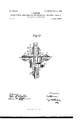
- FIG. 3 is a section on the line C O of Fig. 2,showing one construction of reliefvalve arrangement according to this invention and suitable for use with one or each end of an engine-cylinder or with a steam chest or chests fitted with a piston distributing valve or valves.
- Fig. 4 is a plan view showing a set of six relief-valves connected together through a common steam-supply pipe,
- Figs. 5 and 6 are respectively a front elevation and a side elevation of part of a locomotive-boiler with a three-Way valve for connecting the common steam-supply pipe of the several valves shown in Fig. 4 to a steampipe in the boiler and to a steam-relief pipe.
- Figs. 7, 8, and 9 are similar views to Figs. 1, 2, and 3, respectively showing a modified construction of relief-valve adapted to be coupled to acommon steam-pipe, as in Fig. 4,Fig.
- Fig. 10 is a vertical section on the line D D of Fig. 11, and Fig. 11 is a horizontal section on the line E E of Fig. 10, showing another modified construction of relief-valve with means (shown in dotted lines) for supporting the same in position for use.
- Fig. 12 is a vertical section showing a further-modified construction of relief-valve provided With means for preventing escape of steam from the steam supply pipe when. the relief ⁇ valve proper is open.
- Fig. 13 is a similar viewto Fig. 10, showing another modified construction.
- Figs. 14 and 15 are respectively side and end elevations, each partly in section; and Fig.
- FIG. 16 is a plan showing how a valve of the kind shown in Figs. 10 and 11 can be connected to the-two cylinders and steam-chest of a locomotive-engine.
- Figs. 17 and 18 are respectively front and side elevations, on a relatively small scale, of part 0falocon1otive boiler with a three-way valve for controlling the supply of steam and also the steam-relief plpe.
- the reliefvalve casing a which may conveniently be a casting, is formed at one portion-say its lower end portion, as shown-with a cylindrical valve-chamber I), that is closed at the outer end by a screw-plug 0, having an inward extension d, and is provided with a lateral steam-inlet branch 6, that communicates with the said valve-chamber through a contracted opening f and is adapted to be connected, as by a screw-union g, to a steam-pipe h, leading to a boiler or to the steam-chest of a steam-engine.
- the opposite portion of the casing asay the upper portion-is provided with a water-relief passage 70, the outer end portion of which is horizontal and extends through a lateral branch m, adapted to be connected, as by a screw-union n, to a waterrelief pipe 0, connected to one or to each end of an engine-cylinder or to a steam chest or chests to be relieved of water of condensation, the inner end portion of the said passage It being arranged centrally of the casing a and valve-chamber Z) and terminating in the latter.
- annular water-outlet passage 19 Extending around the inner central portion of the water-relief passage 7r is an annular water-outlet passage 19, that communicates with the valve-chamber Z1 through a circular row of ports or passages q and also with a laterally-extending water-outlet passage 1', that is adapted to be connected, as by a screw-union s, to a drain-pipe t.
- the inner end of the water-relief passage is; and the inner ends of the ports or passages q around the same terminate in a fiat circular valveface it and are controlled by a tlat disk-like relief-valve n, that is of smaller diameter than the interior of the valve-chamber b, in which it is placed, so that it will not be liable to become held fast therein by oily matter that may gain access thereto.
- the several water-relief valves for the cylinders w, or cylinders in and valve-chests (1:, of a locomotive or other engine may, as shown in Fig. 4., conveniently have their steam-inlet branches 6 connected to a common steamsupply pipe 7t, that is connected to the boiler through a hand-operated three-way cock .2, Figs. 5 and 6, one branch, 1, of which is con nected to the steam-space 2 of the boiler 2 through a pipe 3, another branch, 4, of which is connected to the steam-pipe h, common to the valve-chain hers I) of the several relief-val ve arrangements, Fig. 4:, and the third branch, 5, of which is connected to a steam-relief or waste pipe 6.
- each water-relief valve as shown in Figs. 7, S, and 9, with two oppositely-arranged steam-inlet branches 8 e to its valve-chamber I), so that the several valve-chambers can be connected up in series to intermediate pipes to form a continuous steam passage or pipe 7t, that is connected at one point to the boiler through a three-way valve .2, such as described.
- the upper portion of the relief-passage may in this case conveniently be arranged vertically and in line with the lower portion, as shown, so that the branch on can be screwed direct to -the bottom of an engine-cylinder w, Fig. 8, or steam-chest.
- valve-casing is made in two main partsviz., a hollow cylindrical part a,that forms the valve-chamber 12, and a hub-like part a in which the water relief and outlet passages are formedthese two parts being secured together, as by screwing, as shown.
- the cylindrical part a which may conveniently be a casting, is formed on its outer side with a centrally-araranged tubular extension 0', that is adapted to be connected by ascrew-union g to a steampipe h for connection to a boiler and on its inner side is formed with a central tubular extension cl, that projects into the valvechamber b and terminates in a flat circular face 10, the steanrpassage through the two extensions c and d and intermediate end wall. of the chamber being preferably contracted at one part-for example, atits inner end, as shown atf.
- the second or hub-like part a of the casing which may also conveniently be formed as a casting, is provided with a suitable nuu1ber-say sixof radially-arranged tubular extensions or branches m, that are adapted at their outer ends to be connected by screw-unionsn to water-relief pipes 0, connected to the ends of engine-cylinders, or to the ends of cylindrical steam-chests, or some to cylinder ends and some to steam-chests.
- the inner end portions of the passages 71) through the said radial extensions or branches m, forming the water-relief passages, are bent at right angles to the outer portions and are arranged in a circular row around a central outlet-passage 15, that extends through an external centrally-arranged tubular extension 16 of the hub-like part a, which is adapted to be connected, as by a screw-union 17, to a Wateroutlet pipe or spout 18.
- the said tubular extension 16 also serves as a convenient means, in conjunction with a nut 19 and an angle-iron or other support 20, for attaching the apparatus to the cylinder casting or framing of an engine.
- the inner ends of the water relief and outlet passages 7c and 15 respectively terminate in a circular valve-face it and are controlled by a flat disk-like relief-valve i), that is of smaller diameter than the interior of the valve-chamber Z), for the purpose hereinbefore mentioned.
- the tubular extension 9 within the valve-chamber b may be closed by a device that will nnder the action of the steampressure move in a direction to close the relief-valve "u and under the action of the wa- ITO ter-pressure will move in the opposite direction to allow such valve to open and will at the same time prevent or practically prevent escape of steam from the inlet-pipe h.
- a device that will nnder the action of the steampressure move in a direction to close the relief-valve "u and under the action of the wa- ITO ter-pressure will move in the opposite direction to allow such valve to open and will at the same time prevent or practically prevent escape of steam from the inlet-pipe h.
- the steam-inlet pipe 71 for the valve-chamber b of the arrangements shown in Figs. 10, 11', and 12 may be connected to the boiler through a three-way cock, such as hereinbefore described with reference to Figs. 5 and 6.
- the relief-valve will usually be so arranged in use that the valve-chamber b will be at the bottom, in which case the said valve-chamber may be provided with a drain hole 23, Fig. 10, that is normally closed by a removable stopper 24.
- extension (1 with contracted openingf may be omitted, as in the example shown in Fig. 13.
- Figs. 17 and 18 are views similar to Figs. 5
- the communication between the boiler and chambers 17 can be cut off and the chambers thrown into communication with the external atmosphere through the relief-pipe 6, which will relieve the valves 'uof all pressure and permit them to open freely and allow the water of condensation within the relief pipe or pipes o and passages k to flow away through the outlet-passage.
- a water-relief valve for a locomotive or other engine comprising a casing having a valve-chamber provided with a steam-inlet passage adapted to be connected to the steamsupply of said engine, a water-relief passage adapted to be connected to the engine-cylinder or other part from which water of condensation is to be forced, and a water-outlet passage, and a relief-valve loosely arranged within said valve-chamber and adapted to sim ultaneously close the communication between the inner and adjacent ends of said relief and outlet passages.
- a water-relief valve for a locomotive or other engine comprising a casing having a valve-chamber provided with a steam-inlet passage adapted to be connected to the steamsupply of said engine, a water-relief passage adapted to be connected to the engine-cylin- -der or other part from which water of condensation is to be forced, and a water-outlet passage, the inner ends of the water relief and outlet passages terminating in a common plane in said valve-chamber, and a reliefvalve' that is loosely arranged within said valve-chamber and is adapted to simultaneously close said water relief and outlet pas sages.
- a water-relief valve for a locomotive or other engine comprising a casing having a IIO valve-chamber provided with a steam-inlet and outlet passages being arranged around one another and terminating in a common plane in said valve-chamber, and a reliefvalve loosely arranged within said valve-.
- a water-relief valve for a locomotive or other engine comprising a casing having a valve-chamber provided with a steam-inlet passage adapted to be connected to the steamsupply of said engine, a water-relief passage adapted to be connected to an engine-cylinder or other part from which water of condensation is to be forced, and a Water'outlet passage leading to the external atmosphere, the inner end portions of said water relief and outlet passages terminating in a common plane, a relief-valve loosely arranged within said valve-chamber and having a fiat face adapted to simultaneously close the inner ends of said relief and outlet passages, and a stop located within said valve-chamber and adapted to limit the extent of opening of said valve.
- a water-relief valve for a locomotive or other engine comprising a casing having a valve-chamber provided with a steam-inlet passage adapted to be connected to the steamsupply of said engine, a number of water-relief passages adapted to be separately connected to parts of the engine from which wa ter of condensation is to be forced, and a water-outlet passage, said water relief and outlet passages having their inner ends terminating within said valve-chamber, and a relief valve loosely arranged in said valve chamber and adapted normally to close the inner ends of said water relief and outlet passages.
- a water-relief valve for a locomotive or other engine comprising a casing having a valve-chamber provided with a steam-inlet passage adapted to be connected to the steamsupply of said engine, a number of Water-relief passages adapted to be separately connected to parts of the engine from which water of condensation is to be forced, the inner end portions of said relief-passages terminating within valve-chamber and arranged around a common center, a water-outlet passage having its inner end portion arranged between the inner end portions of said reliefpassages and also terminating within said valve-chamber, and a valve loosely arranged within said valve-chamber and adapted to simultaneously control the inner ends of said water relief and outlet passages.
- a water-relief valve for a locomotive or other engine comprising a casing having a valve-chamber the outer end of which is provided with an external centrally-arranged steam-inlet branch, adapted to be connected to the steam-supply of said engine, a number of radially arranged water relief passages adapted to be separately connected to parts of the engine from which water of condensation is to be forced, and a centrally-arranged water-outlet passage, the inner end portions of said water-relief passages being arranged around the inner end of said outlet-passage and the inner ends of all of said relief and outlet passages terminating in a common flat valve-face at the inner end of said valvechamber, and a flat valve loosely arranged in said valve-chamber and adapted to bear on said valve-face and simultaneously close the ends of the said passages therein.
- a water-relief valve for a locomotive or other engine comprising a casing having a valve-chamber the outer end of which is provided with centrally-arranged inner and outer extensions having a steam-passage therethrough, the outer extension being adapted to be connected to the steam-supply of said engine, a number of radially-arranged waterrelief passages having their outer ends adapted to be separately connected to parts of the engine from which water of condensation is to be forced and having their inner end portions bent and arranged in a circle coaxial to the casing, and a centrally-arranged wateroutlet passage having its outer end adapted to be connected to a drain-pipe, the inner ends of said water relief and outlet passages terminating in a common flat valve-face at the inner end of said valve-chamber, and a flat valve arranged loosely within said valvechamber between said inner extension and valve face and adapted to normally bear against the latter and close the passages therein, substantially as described.
- a water'relief valve for a locomotive or other engine comprising a casing made in two main parts adapted to be connected together, one of said parts being formed with a valve-chamber the outer end of which is provided with centrally-arranged inner and outer extensions having therethrough a steam-passage adapted to be connected to a steam-supply, and the other of said parts being formed with a centrally-arranged wateroutlet passage and a number of radially-arranged water-relief passages the outer ends of which are provided with pipe-unions and the inner end portions of which, as well as the inner end of said outlet-passage, terminate in a common valve-face forming the inner end of said valve-chamber when the two parts of the casing are connected together, and a fiat valve loosely arranged within said valve-chain her and adapted to close the inner ends of said water relief and outlet passages, substantially as described.
- A'water-relief valve for a locomotive or other engine comprising a valve-casing having a valve-chamber the outer end of which is provided with inner and outer tubular extensions, and water relief and outlet passages having their inner ends terminating in a common plane at the inner end of said valvechamber, the outer ends of said extension, water-relief passage,and water-outlet passage being adapted to be connected respectively to a steam-pipe, a water-relief pipe and a drain-pipe, a valve loosely arranged within said valve-chamber and adapted to simultaneously close the ends of the passages in said valve-face, and an endwise-movable device arranged to fit said inner tubular extension and form a more or less fluid-tight joint therewith and to bear against said valve, substan-' tially as'described.
- a Water-relief valve for a locomotive or other engine comprising a valve-casing having a valve-chamber the outer end of which is provided with inner and outer tubular ex-' tensions, and water relief and outlet passages having their inner ends terminating in a common plane at the inner end of said valvechamber, the outer ends of said extension, water-relief passage, and water-outlet passage being adapted to be connected respectively to a steam-pipe, a water-relief pipe and a drain-pipe, a valve loosely arranged within said valve-chamber and adapted to simultaneously close the ends of the'passages in said valve-face, and a hollow cap or cover adapted to slide endwise on said inner tubular extension and form a more or less fluid-tight joint therewith and to bear against said valve, substantially as described for the purpose specified.
- a water-relief valve for a locomotive or other engine comprising a valve-casing having a valve-chamber the outer end of which is provided with inner and outer tubular extensions, and Water relief and outlet passages having their inner ends terminating in a common plane at the inner end of said valve-- chamber, the outer ends of said extension,
- water-relief passage, and water-o u'tlet passage being adapted to be connected respectively to a steam-pipe, a water-relief pipe and a drain-pipe, a valve loosely arranged within said valve-chamber and adapted to simultaneously close the ends of the passages in said valve-face, and an endwise-movable closing device arranged to bear against said valve and adapted to fit and slide endwise on said inner tubular extension, one of these two engaging parts being formed with a number of annular grooves arranged adjacent to the other part, substantially as described for the purpose specified.
- I I v 13 13.
- a water-relief valve for a locomotive or other engine comprising a casing having a valve-chamber provided with a steam-inlet passageadapted to be connected to the steamsnpply of said engine, a Water-relief passage connected with the engine-cylinder or otherpart from which water of condensation is to be forced, and a water-outlet passage, and a relief valve loosely arranged within said valve-chamber and adapted to directly engage and close the adjacent ends of said passages.
Description
' Nd. 720,499. PATBNTED FEB. 10,1903.
A. SPENCER. RELIEP'VALVE ARRANGEMENT FOR Locomonvs QR OTHER-ENGINES.
' APPLIOATIOIQIILED 0M. 6, 1903.
10 MODEL. 11 sums-8111:2311
The uonms F zns co, PnoTouma, WASHINGTON. n, c.
No. 720,499. PATENTED 1 312.10, 1903.
' v A. SPENGER. RELIEF VALVE ARRANGEMENT FORLOGOMOTIVE OR OTHER ENGINES.
APPLICATION FILED OUT. 6, 1902.
H0 MODEL. 1 11 SHEETS-SHEET 2.
PATENTBD 'FEB. 10, 1903.
SPENCER. V EEL EE VALVE ARRANGEMENT FOR LOGOMOTIVE OR OTHER ENGINES.
APPLICATION FILED 0OT.6, 1902. no MODEL.
' 11 SHEETS-SHEET 3.
m: Mamas mzns co.. wo'ro-umu. wAsume'rop, D. c.
'PA ENTED FEB. 10, 1903.
' A. SPENCER. Y RELIEF VALVE ARRANGEMENT EoR LOGOMOTIVE OR OTHER ENGINES.
1 1 sEEETs-sEE T 4.
V APPLIOATION FILED 00E. 6, 1902.
no MODEL.
n: NORRIS Fsrzns ca, Puoraurnu. WASHINGTON, n. c.
PATENTED FEB. 1.0, 1903.
No. 720,499. I
A. SPENCER.
RELIEF VALVE ARRANGEMENT FOR LOGOMOTIVE OR OTHER ENGINES.
' APPLICATION FILED OUT. 6, 1902.
ujfli-H-FS-SHEEIfi.
1m MODEL.
n4: NOIINB Pnms co, r'mmmn'wo. WASHINGTON. o. c.
PATENTED FEB. l0,- 1903.
A. SPENCER. RELIEF VALVE ARRANGEMENT FOR LOGOMOTIVE OR OTHER ENGINES APPLIQATION FILED 001'. s, 1902."
11 SHEET8-8HEET 6.
N0 MODEL.
110,720,499. 1 PATENTED FEB. 10,1903.
' A. SPENCER.
RELIEF VALVE ARRANGEMENT FOR LOCOMOTIVE OR OTHER ENGINES.- AfPLwATIoR FILED 001'. e, 1002. no nonnn. 11 sums-sum 7 Tn: Nomus PETERS cm, Mord-Luna. wsmuafou, D, cf
No- 720,499. PATENTED FEB. 10, 1903.
' A; SPENCER. 7 RELIEF VALVE ARRANGEMENT FOR LOOGMOTI-VE OR OTHER ENGINES.
APPLICATION FILED OUT. 6, 1902.
N0 MODEL. 11 SHEETS-SHEET 8.
PATENTED FEB. 10, 1903.
A. SPENCER. RELIEF VALVE ARRANGEMENT FOR LOGOMOTIV-E OR OTHER ENGINES.
APPLICATION FILED OUT- 6. 1902.
11 SHEETS-SHEET 9.
N0 MODEL.
- PATENTED FEB. 10, 1903.
"A. SPENCER.
' RELIEF VALVE ARRANGEMENT FOR LOGOMOTIVE OR OTHER ENGINES.
IAPIPLIOATION FILED 001'. 6, 1902.
K0 MODEL. 11 SHEETS-SHEET 10.
a PATENTED' FEB, 10, 190a. K A. SPENCER. RELIEPVALVE ARRANGEMENT FOR LOGOMOTIVE 0.11 02mm ENGINES.
APPLICATION FILED 0013.6, 1902.
11 SHEETSSHEET 11.
N0 MODEL.
UNITED STATES PATENT OEEroE.
ALEXANDER SPENCER, OF LONDON, ENGLAND.
RELIEF-VALVE ARRANGEMENT .FOR LOCOMOTIVE OR OTHER ENGINES.
SPECIFICATION forming part of Letters Patent No. 720,499, dated February 10, 1903.
Application filed October 6, 1902. Serial No. 126,248. (No model.)
T aZZ whom, it may concern.-
Be it known that I, ALEXANDER SPENCER, a subject of the King of Great Britain and Ireland, residing at London, England, have invented Improvements in Relief-Valve Arrangements for Locomotive or other Engines, of which the following is a specification.
This invention has reference to improvements in relief-valve arrangements for loco-' motive and other engines for enabling water of condensation to escape from either end of the engine cylinder or cylinders and, it may be, from the steam chest or chests of such engine when the same are fitted with piston or like steam-distributing valves, the object being to provide a valve arrangement for the purpose mentioned that will not be readily liable to become inoperative or unreliable in consequence of the presence therein of greasy matter.
The invention consists for this purpose in a relief-valve arrangement comprising a casing formed with a valve-chamber and provided with a steam-inlet passage adapted to be directly or indirectly connected to the steam-boiler from which steam is supplied to the engine with which the valve arrangement is used, with one or more water-relief passages adapted to be connected through a suitable pipe or pipes to one or both ends of the engine cylinder or cylinders and, it may be, to the steam chest or chests of the engine, and a water outlet passage terminating at its outer end in the external atmosphere, the inner ends of the said passages terminating in the valve-chamber and the inner ends of the water relief and outlet passages terminating in a common plane and being controlled by a single loose relief-valve that is arranged in the said valve-chamber and is common to the water relief and outlet passages which it is 1, and Fig. 3 is a section on the line C O of Fig. 2,showing one construction of reliefvalve arrangement according to this invention and suitable for use with one or each end of an engine-cylinder or with a steam chest or chests fitted with a piston distributing valve or valves. Fig. 4 is a plan view showing a set of six relief-valves connected together through a common steam-supply pipe,
four of the valves serving for the respective ends ofthe two cylinders of a locomotive-engine and the remaining two valves serving for the respective steam-chests of such cylinders. Figs. 5 and 6 are respectively a front elevation and a side elevation of part of a locomotive-boiler with a three-Way valve for connecting the common steam-supply pipe of the several valves shown in Fig. 4 to a steampipe in the boiler and to a steam-relief pipe. Figs. 7, 8, and 9 are similar views to Figs. 1, 2, and 3, respectively showing a modified construction of relief-valve adapted to be coupled to acommon steam-pipe, as in Fig. 4,Fig. 8 also showing in dottedlines a part of an engine-cylinder towhich such relief-valve is attached. Fig. 10 is a vertical section on the line D D of Fig. 11, and Fig. 11 is a horizontal section on the line E E of Fig. 10, showing another modified construction of relief-valve with means (shown in dotted lines) for supporting the same in position for use. Fig. 12 is a vertical section showing a further-modified construction of relief-valve provided With means for preventing escape of steam from the steam supply pipe when. the relief} valve proper is open. Fig. 13 is a similar viewto Fig. 10, showing another modified construction. Figs. 14 and 15 are respectively side and end elevations, each partly in section; and Fig. 16 is a plan showing how a valve of the kind shown in Figs. 10 and 11 can be connected to the-two cylinders and steam-chest of a locomotive-engine. Figs. 17 and 18 are respectively front and side elevations, on a relatively small scale, of part 0falocon1otive boiler with a three-way valve for controlling the supply of steam and also the steam-relief plpe.
Referring to Figs. 1, 2, and 3, the reliefvalve casing a, which may conveniently be a casting, is formed at one portion-say its lower end portion, as shown-with a cylindrical valve-chamber I), that is closed at the outer end by a screw-plug 0, having an inward extension d, and is provided with a lateral steam-inlet branch 6, that communicates with the said valve-chamber through a contracted opening f and is adapted to be connected, as by a screw-union g, to a steam-pipe h, leading to a boiler or to the steam-chest of a steam-engine. The opposite portion of the casing asay the upper portion-is provided with a water-relief passage 70, the outer end portion of which is horizontal and extends through a lateral branch m, adapted to be connected, as by a screw-union n, to a waterrelief pipe 0, connected to one or to each end of an engine-cylinder or to a steam chest or chests to be relieved of water of condensation, the inner end portion of the said passage It being arranged centrally of the casing a and valve-chamber Z) and terminating in the latter. Extending around the inner central portion of the water-relief passage 7r is an annular water-outlet passage 19, that communicates with the valve-chamber Z1 through a circular row of ports or passages q and also with a laterally-extending water-outlet passage 1', that is adapted to be connected, as by a screw-union s, to a drain-pipe t. The inner end of the water-relief passage is; and the inner ends of the ports or passages q around the same terminate in a fiat circular valveface it and are controlled by a tlat disk-like relief-valve n, that is of smaller diameter than the interior of the valve-chamber b, in which it is placed, so that it will not be liable to become held fast therein by oily matter that may gain access thereto.
The several water-relief valves for the cylinders w, or cylinders in and valve-chests (1:, of a locomotive or other engine may, as shown in Fig. 4., conveniently have their steam-inlet branches 6 connected to a common steamsupply pipe 7t, that is connected to the boiler through a hand-operated three-way cock .2, Figs. 5 and 6, one branch, 1, of which is con nected to the steam-space 2 of the boiler 2 through a pipe 3, another branch, 4, of which is connected to the steam-pipe h, common to the valve-chain hers I) of the several relief-val ve arrangements, Fig. 4:, and the third branch, 5, of which is connected to a steam-relief or waste pipe 6. By this arrangement the pressure in the valve-chambers b can be controlled, and hence the steam-pressure on the valve correspondingly controlled, so that water of condensation in the engine-cylinders and valvechests can escape at a pressure considerably below the boiler-pressure when this may be desired. For an arrangement of this kind it is convenient to construct each water-relief valve, as shown in Figs. 7, S, and 9, with two oppositely-arranged steam-inlet branches 8 e to its valve-chamber I), so that the several valve-chambers can be connected up in series to intermediate pipes to form a continuous steam passage or pipe 7t, that is connected at one point to the boiler through a three-way valve .2, such as described. The upper portion of the relief-passage may in this case conveniently be arranged vertically and in line with the lower portion, as shown, so that the branch on can be screwed direct to -the bottom of an engine-cylinder w, Fig. 8, or steam-chest.
In the modified construction of water-relief valve shown in Figs. 10 and 11 the valve-casing is made in two main partsviz., a hollow cylindrical part a,that forms the valve-chamber 12, and a hub-like part a in which the water relief and outlet passages are formedthese two parts being secured together, as by screwing, as shown. The cylindrical part a, which may conveniently be a casting, is formed on its outer side with a centrally-araranged tubular extension 0', that is adapted to be connected by ascrew-union g to a steampipe h for connection to a boiler and on its inner side is formed with a central tubular extension cl, that projects into the valvechamber b and terminates in a flat circular face 10, the steanrpassage through the two extensions c and d and intermediate end wall. of the chamber being preferably contracted at one part-for example, atits inner end, as shown atf. The second or hub-like part a of the casing, which may also conveniently be formed as a casting, is provided with a suitable nuu1ber-say sixof radially-arranged tubular extensions or branches m, that are adapted at their outer ends to be connected by screw-unionsn to water-relief pipes 0, connected to the ends of engine-cylinders, or to the ends of cylindrical steam-chests, or some to cylinder ends and some to steam-chests. The inner end portions of the passages 71) through the said radial extensions or branches m, forming the water-relief passages, are bent at right angles to the outer portions and are arranged in a circular row around a central outlet-passage 15, that extends through an external centrally-arranged tubular extension 16 of the hub-like part a, which is adapted to be connected, as by a screw-union 17, to a Wateroutlet pipe or spout 18. The said tubular extension 16 also serves as a convenient means, in conjunction with a nut 19 and an angle-iron or other support 20, for attaching the apparatus to the cylinder casting or framing of an engine. The inner ends of the water relief and outlet passages 7c and 15 respectively terminate in a circular valve-face it and are controlled by a flat disk-like relief-valve i), that is of smaller diameter than the interior of the valve-chamber Z), for the purpose hereinbefore mentioned.
To prevent the escape of steam from the boiler through the valve arrangement when the water-relief valve o is forced from its seat '10 by escaping water of condensation under the action of either of the engine-pistons or piston-valves, the tubular extension 9 within the valve-chamber b may be closed by a device that will nnder the action of the steampressure move in a direction to close the relief-valve "u and under the action of the wa- ITO ter-pressure will move in the opposite direction to allow such valve to open and will at the same time prevent or practically prevent escape of steam from the inlet-pipe h. In the arrangement .shown for this purpose in Fig. 12 the said inner tubular extension d is made in the form of a hollow cylinder over which is fitted a movable hollow plunger or cap 21, the closed end of which bears against the relief-valve "u, a more or less fluidtight joint being maintained between the two parts by suitable packing means that will permit of the plunger or cap moving freely. For this purpose one of the two engaging parts d and 21 may be formed with a number of annular grooves 22, that are spaced apart and serve to prevent or retard passage of steam between the two said parts. In the example the grooves 22 are formed in the extension d.
The steam-inlet pipe 71 for the valve-chamber b of the arrangements shown in Figs. 10, 11', and 12 may be connected to the boiler through a three-way cock, such as hereinbefore described with reference to Figs. 5 and 6. In each case the relief-valve will usually be so arranged in use that the valve-chamber b will be at the bottom, in which case the said valve-chamber may be provided with a drain hole 23, Fig. 10, that is normally closed by a removable stopper 24.
In some cases the extension (1 with contracted openingf may be omitted, as in the example shown in Fig. 13.
Figs. 14 and 15 are respectively side and end elevations, each partly in section; and Fig. 16 is a plan showing an arrangement of pipes employed when a relief-valve furnished with a number of radial extensions or branches-such as described with reference to Figs. 10 to 13, inclusiveis connected to the cylinders w and steam-chest 0c of a locomotive-engine.
Figs. 17 and 18 are views similar to Figs. 5
and 6, respectively, but to a smaller scale, showing the branch 1 of the three-way cock .2 connected, through a pipe 3, to the main steam-supply pipe 25 at a partthereof within the steam-dome 26 of the boiler 2.
The operation in each case is as follows:
When the steam-inlet passage through the inlet branch 6 or e is connected to the boiler 2, Figs. 5 and 6, or other source of steampressure and the water-relief passage or passages is or are connected to one or each end.
the engine cylinder or cylinders orsteam chest .or chests such water will under the pressure of the engine piston or pistons or piston distributing valve or valves, asfthe case may be, force the water-relief valve '0 from 01f its seat in such a manner as to allow of its escaping through the corresponding water-relief pipe and passage 0 and k and the outlet-passages q p and pipe t, Figs. 1 to 3 and 7 to 9, or outlet-passage 15 and pipe 18, Figs. 10 to 13, after which the relief-valve 1) will be again automatically closed, the said valve being loose, and thereforeunrestrained .in its opening and closing movements by the sides of the valve-chamber b. By means of the three-Way valve 2 the communication between the boiler and chambers 17 can be cut off and the chambers thrown into communication with the external atmosphere through the relief-pipe 6, which will relieve the valves 'uof all pressure and permit them to open freely and allow the water of condensation within the relief pipe or pipes o and passages k to flow away through the outlet-passage.
- What I claim is- 1. A water-relief valve for a locomotive or other engine, comprising a casing having a valve-chamber provided with a steam-inlet passage adapted to be connected to the steamsupply of said engine, a water-relief passage adapted to be connected to the engine-cylinder or other part from which water of condensation is to be forced, and a water-outlet passage, and a relief-valve loosely arranged within said valve-chamber and adapted to sim ultaneously close the communication between the inner and adjacent ends of said relief and outlet passages. V
2. A water-relief valve for a locomotive or other engine, comprising a casing having a valve-chamber provided with a steam-inlet passage adapted to be connected to the steamsupply of said engine, a water-relief passage adapted to be connected to the engine-cylin- -der or other part from which water of condensation is to be forced, and a water-outlet passage, the inner ends of the water relief and outlet passages terminating in a common plane in said valve-chamber, and a reliefvalve' that is loosely arranged within said valve-chamber and is adapted to simultaneously close said water relief and outlet pas sages.
3.- A water-relief valve for a locomotive or other engine, comprising a casing havinga IIO valve-chamber provided with a steam-inlet and outlet passages being arranged around one another and terminating in a common plane in said valve-chamber, and a reliefvalve loosely arranged within said valve-.
chamber and having a flat face adapted to simultaneously close the inner ends of said relief and outlet passages.
4. A water-relief valve for a locomotive or other engine, comprising a casing having a valve-chamber provided with a steam-inlet passage adapted to be connected to the steamsupply of said engine, a water-relief passage adapted to be connected to an engine-cylinder or other part from which water of condensation is to be forced, and a Water'outlet passage leading to the external atmosphere, the inner end portions of said water relief and outlet passages terminating in a common plane, a relief-valve loosely arranged within said valve-chamber and having a fiat face adapted to simultaneously close the inner ends of said relief and outlet passages, and a stop located within said valve-chamber and adapted to limit the extent of opening of said valve.
5. A water-relief valve for a locomotive or other engine, comprising a casing having a valve-chamber provided with a steam-inlet passage adapted to be connected to the steamsupply of said engine, a number of water-relief passages adapted to be separately connected to parts of the engine from which wa ter of condensation is to be forced, and a water-outlet passage, said water relief and outlet passages having their inner ends terminating within said valve-chamber, and a relief valve loosely arranged in said valve chamber and adapted normally to close the inner ends of said water relief and outlet passages.
6. A water-relief valve for a locomotive or other engine, comprising a casing having a valve-chamber provided with a steam-inlet passage adapted to be connected to the steamsupply of said engine, a number of Water-relief passages adapted to be separately connected to parts of the engine from which water of condensation is to be forced, the inner end portions of said relief-passages terminating within valve-chamber and arranged around a common center, a water-outlet passage having its inner end portion arranged between the inner end portions of said reliefpassages and also terminating within said valve-chamber, and a valve loosely arranged within said valve-chamber and adapted to simultaneously control the inner ends of said water relief and outlet passages.
7. A water-relief valve for a locomotive or other engine, comprising a casing having a valve-chamber the outer end of which is provided with an external centrally-arranged steam-inlet branch, adapted to be connected to the steam-supply of said engine, a number of radially arranged water relief passages adapted to be separately connected to parts of the engine from which water of condensation is to be forced, anda centrally-arranged water-outlet passage, the inner end portions of said water-relief passages being arranged around the inner end of said outlet-passage and the inner ends of all of said relief and outlet passages terminating in a common flat valve-face at the inner end of said valvechamber, and a flat valve loosely arranged in said valve-chamber and adapted to bear on said valve-face and simultaneously close the ends of the said passages therein.
8. A water-relief valve for a locomotive or other engine, comprising a casing having a valve-chamber the outer end of which is provided with centrally-arranged inner and outer extensions having a steam-passage therethrough, the outer extension being adapted to be connected to the steam-supply of said engine, a number of radially-arranged waterrelief passages having their outer ends adapted to be separately connected to parts of the engine from which water of condensation is to be forced and having their inner end portions bent and arranged in a circle coaxial to the casing, and a centrally-arranged wateroutlet passage having its outer end adapted to be connected to a drain-pipe, the inner ends of said water relief and outlet passages terminating in a common flat valve-face at the inner end of said valve-chamber, and a flat valve arranged loosely within said valvechamber between said inner extension and valve face and adapted to normally bear against the latter and close the passages therein, substantially as described.
9. A water'relief valve for a locomotive or other engine, comprising a casing made in two main parts adapted to be connected together, one of said parts being formed with a valve-chamber the outer end of which is provided with centrally-arranged inner and outer extensions having therethrough a steam-passage adapted to be connected to a steam-supply, and the other of said parts being formed with a centrally-arranged wateroutlet passage and a number of radially-arranged water-relief passages the outer ends of which are provided with pipe-unions and the inner end portions of which, as well as the inner end of said outlet-passage, terminate in a common valve-face forming the inner end of said valve-chamber when the two parts of the casing are connected together, and a fiat valve loosely arranged within said valve-chain her and adapted to close the inner ends of said water relief and outlet passages, substantially as described.
10. A'water-relief valve for a locomotive or other engine, comprising a valve-casing having a valve-chamber the outer end of which is provided with inner and outer tubular extensions, and water relief and outlet passages having their inner ends terminating in a common plane at the inner end of said valvechamber, the outer ends of said extension, water-relief passage,and water-outlet passage being adapted to be connected respectively to a steam-pipe, a water-relief pipe and a drain-pipe, a valve loosely arranged within said valve-chamber and adapted to simultaneously close the ends of the passages in said valve-face, and an endwise-movable device arranged to fit said inner tubular extension and form a more or less fluid-tight joint therewith and to bear against said valve, substan-' tially as'described. v
11. A Water-relief valve for a locomotive or other engine, comprising a valve-casing having a valve-chamber the outer end of which is provided with inner and outer tubular ex-' tensions, and water relief and outlet passages having their inner ends terminating in a common plane at the inner end of said valvechamber, the outer ends of said extension, water-relief passage, and water-outlet passage being adapted to be connected respectively to a steam-pipe, a water-relief pipe and a drain-pipe, a valve loosely arranged within said valve-chamber and adapted to simultaneously close the ends of the'passages in said valve-face, and a hollow cap or cover adapted to slide endwise on said inner tubular extension and form a more or less fluid-tight joint therewith and to bear against said valve, substantially as described for the purpose specified.
12. A water-relief valve for a locomotive or other engine, comprising a valve-casing having a valve-chamber the outer end of which is provided with inner and outer tubular extensions, and Water relief and outlet passages having their inner ends terminating in a common plane at the inner end of said valve-- chamber, the outer ends of said extension,
water-relief passage, and water-o u'tlet passage being adapted to be connected respectively to a steam-pipe, a water-relief pipe and a drain-pipe, a valve loosely arranged within said valve-chamber and adapted to simultaneously close the ends of the passages in said valve-face, and an endwise-movable closing device arranged to bear against said valve and adapted to fit and slide endwise on said inner tubular extension, one of these two engaging parts being formed with a number of annular grooves arranged adjacent to the other part, substantially as described for the purpose specified. I I v 13. A water-relief valve for a locomotive or other engine, comprising a casing having a valve-chamber provided with a steam-inlet passageadapted to be connected to the steamsnpply of said engine, a Water-relief passage connected with the engine-cylinder or otherpart from which water of condensation is to be forced, and a water-outlet passage, and a relief valve loosely arranged within said valve-chamber and adapted to directly engage and close the adjacent ends of said passages.
Signed at 77 Cannon street, London, England, this 22d day of September, 1902.
ALEXANDER SPENCER.
Witnesses:
R. T. GLA'SOODINE, PERCY E. MATTOCKS.
Priority Applications (1)
| Application Number | Priority Date | Filing Date | Title |
|---|---|---|---|
| US1902126248 US720499A (en) | 1902-10-06 | 1902-10-06 | Relief-valve arrangement for locomotive or other engines. |
Applications Claiming Priority (1)
| Application Number | Priority Date | Filing Date | Title |
|---|---|---|---|
| US1902126248 US720499A (en) | 1902-10-06 | 1902-10-06 | Relief-valve arrangement for locomotive or other engines. |
Publications (1)
| Publication Number | Publication Date |
|---|---|
| US720499A true US720499A (en) | 1903-02-10 |
Family
ID=2789014
Family Applications (1)
| Application Number | Title | Priority Date | Filing Date |
|---|---|---|---|
| US1902126248 Expired - Lifetime US720499A (en) | 1902-10-06 | 1902-10-06 | Relief-valve arrangement for locomotive or other engines. |
Country Status (1)
| Country | Link |
|---|---|
| US (1) | US720499A (en) |
Cited By (1)
| Publication number | Priority date | Publication date | Assignee | Title |
|---|---|---|---|---|
| US3968816A (en) * | 1974-12-31 | 1976-07-13 | Elazar Tagansky | Cock |
-
1902
- 1902-10-06 US US1902126248 patent/US720499A/en not_active Expired - Lifetime
Cited By (1)
| Publication number | Priority date | Publication date | Assignee | Title |
|---|---|---|---|---|
| US3968816A (en) * | 1974-12-31 | 1976-07-13 | Elazar Tagansky | Cock |
Similar Documents
| Publication | Publication Date | Title |
|---|---|---|
| US720499A (en) | Relief-valve arrangement for locomotive or other engines. | |
| US1215947A (en) | Automatic drifting-valve for locomotives. | |
| US421159A (en) | Island | |
| US405569A (en) | lapag-e | |
| US696847A (en) | Vacuum and water relief valve apparatus for locomotives. | |
| US383426A (en) | William b | |
| US323144A (en) | Valve | |
| US793281A (en) | Valve. | |
| US756903A (en) | Fluid-pump. | |
| US471882A (en) | Steam-actuated valve for engines | |
| US413500A (en) | Brake for locomotives | |
| US406615A (en) | Hydraulic governor for steam-pumps | |
| US677470A (en) | Steam-valve. | |
| US474000A (en) | Intercepting-valve for compound engines | |
| US679950A (en) | Steam-engine. | |
| US339282A (en) | Cut-off device for engines | |
| US644151A (en) | Cylinder relief-valve. | |
| US428892A (en) | Steam-engine | |
| US679949A (en) | Steam-engine. | |
| US344571A (en) | Auxiliary air-accumulator | |
| US376616A (en) | tonkin | |
| US784354A (en) | Means for operating cylinder-cocks. | |
| US486099A (en) | Valve for steam-engines | |
| US146095A (en) | Improvement in steam vacuum-pumps | |
| US1545635A (en) | Drifting and relief valve |