US7180525B1 - Spatial dithering to overcome limitations in RGB color precision of data interfaces when using OEM graphics cards to do high-quality antialiasing - Google Patents
Spatial dithering to overcome limitations in RGB color precision of data interfaces when using OEM graphics cards to do high-quality antialiasing Download PDFInfo
- Publication number
- US7180525B1 US7180525B1 US10/721,634 US72163403A US7180525B1 US 7180525 B1 US7180525 B1 US 7180525B1 US 72163403 A US72163403 A US 72163403A US 7180525 B1 US7180525 B1 US 7180525B1
- Authority
- US
- United States
- Prior art keywords
- graphics
- dithered
- filtering units
- samples
- filtering
- Prior art date
- Legal status (The legal status is an assumption and is not a legal conclusion. Google has not performed a legal analysis and makes no representation as to the accuracy of the status listed.)
- Expired - Lifetime, expires
Links
- 238000001914 filtration Methods 0.000 claims abstract description 124
- 238000009877 rendering Methods 0.000 claims abstract description 31
- 239000000872 buffer Substances 0.000 claims abstract description 29
- 238000012935 Averaging Methods 0.000 claims abstract description 9
- 230000004044 response Effects 0.000 claims abstract description 7
- 238000000034 method Methods 0.000 claims description 19
- 230000001186 cumulative effect Effects 0.000 claims description 14
- 230000003139 buffering effect Effects 0.000 claims description 9
- 238000006073 displacement reaction Methods 0.000 description 8
- 230000008569 process Effects 0.000 description 8
- 239000008186 active pharmaceutical agent Substances 0.000 description 4
- 230000006870 function Effects 0.000 description 4
- 238000012986 modification Methods 0.000 description 4
- 230000004048 modification Effects 0.000 description 4
- 230000014509 gene expression Effects 0.000 description 3
- 238000007792 addition Methods 0.000 description 2
- 238000006243 chemical reaction Methods 0.000 description 2
- 238000010606 normalization Methods 0.000 description 2
- 238000009825 accumulation Methods 0.000 description 1
- 230000009471 action Effects 0.000 description 1
- 238000003491 array Methods 0.000 description 1
- 230000009286 beneficial effect Effects 0.000 description 1
- 230000005540 biological transmission Effects 0.000 description 1
- 238000009795 derivation Methods 0.000 description 1
- 230000011664 signaling Effects 0.000 description 1
- 238000009827 uniform distribution Methods 0.000 description 1
Images


Classifications
-
- G—PHYSICS
- G09—EDUCATION; CRYPTOGRAPHY; DISPLAY; ADVERTISING; SEALS
- G09G—ARRANGEMENTS OR CIRCUITS FOR CONTROL OF INDICATING DEVICES USING STATIC MEANS TO PRESENT VARIABLE INFORMATION
- G09G5/00—Control arrangements or circuits for visual indicators common to cathode-ray tube indicators and other visual indicators
- G09G5/36—Control arrangements or circuits for visual indicators common to cathode-ray tube indicators and other visual indicators characterised by the display of a graphic pattern, e.g. using an all-points-addressable [APA] memory
- G09G5/39—Control of the bit-mapped memory
- G09G5/395—Arrangements specially adapted for transferring the contents of the bit-mapped memory to the screen
- G09G5/397—Arrangements specially adapted for transferring the contents of two or more bit-mapped memories to the screen simultaneously, e.g. for mixing or overlay
-
- G—PHYSICS
- G09—EDUCATION; CRYPTOGRAPHY; DISPLAY; ADVERTISING; SEALS
- G09G—ARRANGEMENTS OR CIRCUITS FOR CONTROL OF INDICATING DEVICES USING STATIC MEANS TO PRESENT VARIABLE INFORMATION
- G09G3/00—Control arrangements or circuits, of interest only in connection with visual indicators other than cathode-ray tubes
- G09G3/20—Control arrangements or circuits, of interest only in connection with visual indicators other than cathode-ray tubes for presentation of an assembly of a number of characters, e.g. a page, by composing the assembly by combination of individual elements arranged in a matrix no fixed position being assigned to or needed to be assigned to the individual characters or partial characters
- G09G3/2007—Display of intermediate tones
- G09G3/2044—Display of intermediate tones using dithering
- G09G3/2051—Display of intermediate tones using dithering with use of a spatial dither pattern
-
- G—PHYSICS
- G09—EDUCATION; CRYPTOGRAPHY; DISPLAY; ADVERTISING; SEALS
- G09G—ARRANGEMENTS OR CIRCUITS FOR CONTROL OF INDICATING DEVICES USING STATIC MEANS TO PRESENT VARIABLE INFORMATION
- G09G5/00—Control arrangements or circuits for visual indicators common to cathode-ray tube indicators and other visual indicators
- G09G5/36—Control arrangements or circuits for visual indicators common to cathode-ray tube indicators and other visual indicators characterised by the display of a graphic pattern, e.g. using an all-points-addressable [APA] memory
- G09G5/363—Graphics controllers
Definitions
- This invention relates generally to the field of computer graphics and, more particularly, to a graphics system which uses spatial dithering to compensate for a loss of sample precision due to buffering and transmission through data interfaces.
- High-quality anti-aliasing involves the generation of a set of samples, and filtering the samples (with an anti-aliasing filter) to generate pixels. It would be desirable if industry standard graphics cards could be used to form a graphics system capable of performing high-quality anti-aliasing. However, industry standard graphics cards generally end up throwing away one or more bits of computed color precision in the process of buffering color values in their internal frame buffers and outputting the color values through data interfaces (such as the Digital Video Interface). There exists a need for a graphics system and methodology capable of compensating for this loss of color precision.
- a graphics system may be configured with a set of graphics accelerators (e.g., industry standard graphics accelerators) and a series of filtering units. Each of the graphics accelerators may couple to a corresponding one of the filtering units. Each of the graphics accelerators may be configured to (a) generate a stream of samples in response to received graphics primitives, (b) add a corresponding dither value to the color components of the samples to obtain dithered color components, (c) buffer the dithered color components in an internal frame buffer, and (d) forward truncated versions of the dithered color components to the corresponding filtering unit.
- the filtering units may be configured to perform a weighted averaging computation on the truncated dithered color components to determine pixel color components.
- a host computer may broadcast a stream of graphics primitives to the set of graphics accelerators.
- each of the graphics accelerators may receive the same set of graphics primitives.
- the dither values corresponding to the set of graphics accelerators may have an average value of 1 ⁇ 2.
- the ones digit of the dither value is aligned with the least significant bit of the sample color component that is to survive truncation.
- Each of the filtering units is configured to support the weighted averaging computation by computing a partial sums (one partial sum for each of red, green and blue) corresponding to a subset of the samples falling in a filter support region.
- the filtering units are configured to add the partial sums in a pipelined fashion.
- a last of the filtering units in the series may be programmably configured to normalize a set of final cumulative sums resulting from said addition of the partial sums in a pipelined fashion.
- a graphics system may be configured to include a set of rendering processors and a series of filtering units. Each of the rendering processors couples to a corresponding one of the filtering units.
- Each rendering processor RP(K) of the set of rendering processors may be configured to (a) generate a stream of samples in response to received graphics primitives, (b) add a dither value D K to a data component (such as red, green, blue or alpha) of each the samples in the stream to obtain dithered data components, (c) buffer the dithered data components in an internal frame buffer, and (d) forward a truncated version of the dithered data components to the corresponding filtering unit.
- the filtering units are configured to perform a weighted averaging computation on the truncated dithered data components to determine pixel data components.
- the rendering processors reside within original equipment manufacturer (OEM) graphics cards (i.e., graphics accelerators). Each of the graphics cards may contain one or more of the rendering processors.
- OEM original equipment manufacturer
- FIG. 1A illustrates a collection C SP of sample positions in a virtual screen space according to one set of embodiments
- FIG. 1B illustrates one embodiment of a subset T K of sample positions used by a corresponding graphics card GC(K);
- FIG. 2 illustrates one embodiment for a set of sample positions generated by a set of graphics cards in a given sample bin in virtual screen space
- FIG. 3 illustrates one embodiment of a graphics system including a set of industry standard graphics cards and a series of filtering units
- FIG. 4 illustrates one embodiment of a set of virtual pixel centers generated by a filtering unit FU(K) in a virtual screen space
- FIG. 5 illustrates one embodiment of a sample filtration computation used to determine pixel values
- FIG. 6 illustrates a portion of the sample filtration computation handled by a single filtering unit according to one embodiment
- FIG. 7 highlights the frame buffer FB(K) and video data port VDP(K) of graphics card GC(K) according to one set of embodiments;
- FIG. 8 presents a tabulated example of a spatial dithering process in a box filtering mode
- FIG. 9 illustrates one embodiment of a graphics system including a set of graphics cards and a series of filtering units, where each of the graphics cards contains two rendering processors;
- FIG. 10 illustrates a methodology for applying spatial dithering to sample data components in a graphics system.
- This detailed description discloses various embodiments of a graphics system architecture that uses (a) a set S GC of standard OEM graphics cards to generate samples and (b) a series S FU of filtering units coupled to the OEM graphics cards.
- the series of filtering units receive samples from the OEM graphics cards and spatially filter the samples to generate video output pixels.
- OEM is an acronym for “original equipment manufacturer”.
- N GC denote the number of OEM graphics cards in the set S GC .
- the OEM graphics cards of the set S GC are denoted as GC( 0 ), GC( 1 ), GC( 2 ), . . . , GC(N GC ⁇ 1).
- the number N GC is a positive integer.
- N FU denote the number of filtering units in the series S FU .
- the filtering units of the series S FU are denoted FU( 0 ), FU( 1 ), FU( 2 ), . . . , FU(N FU ⁇ 1).
- the number N FU is a positive integer.
- a host computer directs the broadcast of graphics data from host memory (i.e., a memory associated with the host computer) to the OEM graphics cards GC( 0 ), GC( 1 ), GC( 2 ), . . . , GC(N GC ⁇ 1).
- the graphics data may specify primitives such as polygons, lines and dots.
- the graphics cards collaboratively generate samples corresponding to a collection C SP of sample positions in a virtual screen space as suggested by FIG. 1A .
- Virtual screen space may be interpreted as being partitioned into an array of bins, each bin being a 1 ⁇ 1 square.
- X V and Y V denote the coordinates of virtual screen space.
- the boundaries of the bins may be defined by lines of the form “X V equal to an integer” and lines of the form “Y V equal to an integer”.
- Each graphics card GC(K) may generate samples corresponding to a subset T K of the collection C SP of sample positions.
- Each sample includes a set of data components such as red, green and blue color components.
- a sample may also include data components such as depth and/or alpha, blur value, brighter-than-bright value, etc.
- V X (K) and V Y (K) represent the horizontal and vertical displacements of rectangular array T K from the origin of virtual screen space.
- M B (K) is the horizontal array resolution
- N B (K) is the vertical array resolution.
- Each graphics card GC(K) may include programmable registers which store the values V X (K), V Y (K), M B (K) and N B (K).
- the vector displacements may be set so that they attain N GC distinct positions within the unit square, e.g., positions that are uniformly distributed (or approximately uniformly distributed) over the unit square. Thus, for every I in the range 0, 1, 2, . . .
- the host computer may direct the broadcast of a stream of primitives corresponding to an animation frame to all the graphics cards.
- Each graphics card GC(K) may receive the stream of primitives, compute (i.e., render) samples at the sample positions of the rectangular array T K based on the received primitives, temporarily store the samples in an internal frame buffer, and then, forward the samples from the internal frame buffer to a corresponding one of the filtering units.
- the samples i.e., the color components of the samples
- the sample rendering hardware in graphics card GC(K) may compute each sample color components with P 1 bits of precision.
- the frame buffer may be configured to store each sample color component with P 2 bits of precision, where P 2 is smaller than P 1 .
- sample color components experience a loss of (P 2 ⁇ P 1 ) bits of precision in the process of being stored into the internal frame buffer.
- Each filtering unit FU(K) receives a stream H K of samples from the corresponding graphics card GC(K).
- the stream H K contains samples computed on the subset T K of sample positions.
- each filtering unit FU(K) may scan through virtual screen space in raster fashion generating virtual pixel centers denoted by the small plus markers, and generating a set of partial sums (e.g., one partial sum for each color plus a partial sum for filter coefficients) at each of the virtual pixel centers based on one or more samples from the stream H K in the neighborhood of the virtual pixel center.
- samples of the stream H K correspond to samples positions of the subset T K .
- These sample positions are denoted as small circles in FIG. 4 .
- the virtual pixel centers are also referred to as filter centers or convolutions centers.
- the filtering units are coupled in a series to facilitate the pipelined accumulation of the sets of partial sums for each video output pixel.
- the array A PC (K) of virtual pixel centers traversed by the filtering unit FU(K) may be characterized by the following programmable parameters: a horizontal spacing ⁇ X(K), a vertical spacing ⁇ Y(K), a horizontal start displacement X Start (K), a vertical start displacement Y Start (K), a horizontal resolution N H (K) and a vertical resolution N V (K).
- the horizontal resolution N H (K) is the number of virtual pixel centers in a horizontal line of the array A PC (K).
- the vertical resolution N V (K) is the number of virtual pixel centers in the vertical line of the array A PC (K).
- the filtering units collaborate to compute a video pixel P at a particular virtual pixel center as suggested by FIG. 5 .
- the video pixel is computed based on a filtration of samples corresponding to sample positions (of the collection C SP ) within a support region centered on (or defined by) the virtual pixel center.
- Each filtering unit FU(K) performs a respective portion of the sample filtration.
- the sample positions falling within the support region are denoted as small black dots. In contrast, sample positions outside the support region are denoted as small circles.
- Each sample S corresponding to a sample position Q within the support region may be assigned a filter coefficient C S based on the sample position Q.
- the filter coefficient C S may be function of the spatial displacement between the sample position Q and the virtual pixel center. In some embodiments, the filter coefficient C S is a function of the radial distance between the sample position Q and the virtual pixel center.
- Each of the color components (r P , g P , b P ) of the video pixel may be determined by computing a weighted summation of the corresponding sample color components of the samples falling inside the filter support region. (A sample is said to fall inside the filter support region when its corresponding sample position falls inside the filter support region.)
- Filtering unit FU(K) may include (or couple to) an input buffer INB(K) (not shown) which serves to buffer N LB horizontal scan lines of samples from the input stream H K .
- the parameter N LB may be greater than or equal to the vertical bin size of a bin neighborhood containing the filter support.
- the bin neighborhood may be a rectangle (or square) of bins. For example, in one embodiment the bin neighborhood is a 5 ⁇ 5 array of bins centered on the bin which contains the virtual pixel position as suggested by FIG. 6 .
- the summation values r P , g P , b P and E P are developed cumulatively in the series of filtering units as follows.
- the first filtering unit FU( 0 ) assigns the values of the partial sums PS r ( 0 ), PS g ( 0 ), PS b ( 0 ) and PS E ( 0 ) to the cumulative sums CS r ( 0 ), CS g ( 0 ), CS b ( 0 ) and CS E ( 0 ) respectively, and transmits these cumulative sums to filtering unit FU( 1 ).
- the series of filtering units collaborate to generate each video pixel in a stream of video pixels.
- the series of filtering units may be driven by a common pixel clock.
- each filtering unit may transmit cumulative sums to the next filtering unit using source-synchronous signaling.
- the last filtering unit FU(N FU ⁇ 1) may forward the stream of video pixels to a digital-to-analog (D/A) conversion device.
- the D/A conversion device converts the video pixel stream to an analog video signal and provides the analog video signal to an analog output port accessible by one or more display devices.
- the last filtering unit FU(N FU ⁇ 1) may forward the video pixel stream to a digital video output port accessible by one or more display devices.
- the filter coefficient C S for a sample S in the filter support region may be determined by a table lookup.
- a radially symmetric filter may be realized by a filter coefficient table, which is addressed by a function of the sample's radial distance with respect to the virtual pixel center.
- the filter support for a radially symmetric filter may be a circular disk as suggested by the example of FIG. 6 . (The support of a filter is the region in virtual screen space on which the filter is defined.)
- the terms “filter” and “kernel” are used as synonyms herein. Let R f denote the radius of the circular support disk.
- Filtering unit FU(K) may compute a normalized square radius U S for a valid sample S by multiplying the sample's square radius by the reciprocal of the filter's square radius:
- the normalized square radius U S may be used to access the filter coefficient table for the filter coefficient C S .
- the filter coefficient table may store filter coefficients indexed by the normalized square radius.
- the filter coefficient table is implemented in RAM and is programmable by host software.
- the filter function i.e., the filter kernel
- the square radius (R f ) 2 of the filter support and the reciprocal square radius 1/(R f ) 2 of the filter support may be programmable.
- Each filtering unit FU(K) may include its own filter coefficient table.
- the entries in the filter coefficient table are indexed according to normalized square distance, they need not be updated when the radius R f of the filter support changes.
- the filter coefficients and the filter radius may be modified independently.
- the filter coefficient table may be addressed with the sample radius D S at the expense of computing a square root of the square radius (D S ) 2 .
- the square radius may be converted into a floating-point format, and the floating-point square radius may be used to address the filter coefficient table.
- the filter coefficient table may be indexed by any of various radial distance measures. For example, an L 1 norm or L 28 norm may be used to measure the distance between a sample position and the virtual pixel center.
- Invalid samples may be assigned the value zero for their filter coefficients. Thus, the invalid samples end up making a null contribution to the pixel value summations.
- filtering hardware internal to the filtering unit FU(K) may be configured to ignore invalid samples. Thus, in these embodiments, it is not necessary to assign filter coefficients to the invalid samples.
- the filtering units may support multiple filtering modes.
- each filtering unit supports a box filtering mode as well as a radially symmetric filtering mode.
- the filtering units may implement a box filter over a rectangular support region, e.g., a square support region with radius R f (i.e. side length 2R f ).
- R f radius of radius
- the filtering units may compute boundary coordinates for the support square according to the expressions X P +R f , X P ⁇ R f , Y P +R f , and Y P ⁇ R f .
- Each sample S in the bin neighborhood may be marked as being valid if the sample's position (X S ,Y S ) falls within the support square, i.e., if X P ⁇ R f ⁇ X S ⁇ X P +R f and Y P ⁇ R f ⁇ Y S ⁇ Y P +R f . Otherwise the sample S may be marked as invalid.
- the filtering units may use any of a variety of filters either alone or in combination to compute pixel values from sample values.
- the filtering units may use a box filter, a tent filter, a cone filter, a cylinder filter, a Gaussian filter, a Catmull-Rom filter, a Mitchell-Netravali filter, a windowed sinc filter, or in general, any form of band pass filter or any of various approximations to the sinc filter.
- the filtering units FU( 0 ), FU( 1 ), FU( 2 ), . . . , FU(N FU ⁇ 1) collaborate to perform a spatial filtration (i.e., an averaging computation) on the color components (r S , g S , b S ) of samples as received from the graphics cards in order to generate corresponding pixel color components (R P , G P , B P ).
- a spatial filtration i.e., an averaging computation
- the precision of the sample color components as received by the filtering units may be smaller than the precision used in the graphics cards to originally compute the sample color components.
- Graphics card GC(K) includes an internal frame buffer FB(K) and a video data port VDP(K) through which the graphics card GC(K) is configured to output video data as suggested by FIG. 7 .
- the video data port VDP(K) is used to transfer the stream H K of samples (corresponding to sample positions of the subset T K ) to the filtering unit FU(K).
- filtering unit FU(K) couples to the video data port VDP(K).
- graphics card GC(K) may compute the color components of samples (corresponding to sample positions of the subset T K ) at a first precision P 1 , temporarily store the sample color components in frame buffer FB(K), and then forward the sample color components from the frame buffer FB(K) to filtering unit FU(K) through the video data port VDP(K).
- the sample color components are truncated down to a second lower precision P 2 imposed by the frame buffer FB(K) and/or the video data port VDP(K).
- a video data port conforming to the Digital Video Interface (DVI) specification may allow only 8 bits per color component, especially for video formats with video clock rate greater than 166 MHz.
- DVI Digital Video Interface
- R S , G S and B S denote the color components of a sample S as computed by the graphics card GC(K) at the first precision P 1 .
- Trn(R S ), Trn(G S ) and Trn(B S ) represent the truncated sample color components as sent to the filtering unit (through the sample stream H K ) at the second lower precision P 2 .
- Filtering unit FU(K) computes its partial sums based on the truncated color components Trn(R S ), Trn(G S ) and Trn(B S ) received from the video data port VDP(K).
- the truncated color components Trn(R S ), Trn(G S ) and Trn(B S ) take the roles of r S , g S and b S respectively in the filtration computation described above.
- graphics card GC(K) may be configured to round the color components R S , G S and B S of each computed sample S to the nearest state of the lower precision operand (i.e., the precision P 2 operand).
- filtering unit FU(K) computes its partial sums based on the rounded color components Trn(R S +1 ⁇ 2), Trn(G S +1 ⁇ 2) and Trn(B S +1 ⁇ 2).
- the rounding algorithm induces less error on average than the pure truncation algorithm.
- the set of graphics cards GC( 0 ), GC( 1 ), . . . , GC(N GC ⁇ 1) may apply a spatial dithering operation to the sample color components prior to buffering and forwarding the sample color components to the filtering units.
- Each graphics card GC(K), K 0, 1, 2, . . .
- the dithered color values R S ′, G S ′ and B S ′ of the sample S are then buffered and forwarded to the filtering unit FU(K) through the video data port VDP(K) instead of the originally computed color values R S , G S and B S .
- the dithered color values R S ′, G S ′ and B S ′ get truncated down to the lower precision values Trn(R S ′), Trn(G S ′) and Trn(B S ′).
- the filtering unit FU(K) computes its partial sums based on the truncated color values Trn(R S ′), Trn(G S ′) and Trn(B S ′).
- the series of filtering units FU( 0 ), FU( 1 ), . . . , FU(N FU ⁇ 1) compute the color components of a video pixel P by accumulating the partial sums and normalizing the final sum as described above.
- the dithering operation allows the pixel color components computed by the series of filtering units to more closely approximate the ideal pixel color components which would be obtained from performing the same summation and normalization computations on the original high-precision (i.e., precision P 1 ) sample color components R S , B S and G S .
- the set of dither values may approximate a uniform distribution of numbers between 1 ⁇ 2 ⁇ A and 1 ⁇ 2+A, where A is a rational number greater than or equal to one.
- the dither radius A may be programmable. In one particular embodiment, A equals one.
- the least significant bit position of the sample color values R S , G S and B S which is to survive truncation is aligned with the ones bit position of the dither value operand. Equivalently, the most significant bit position of the sample color values which gets discarded in the truncation is aligned with the 1 ⁇ 2 bit position of the dither value operand.
- FIG. 8 presents a tabulated example of the beneficial effects of spatial dithering the red color channel in the case where a series of 16 filtering units are configured to perform a box filtering on the samples in each bin to determine video pixels.
- the tabulated example focuses on the red color channel, but it is to be understood that spatial dithering may be applied to any or all of the color channels and non-color channels such as alpha.
- Each graphics card GC(K) computes a red color value R K for a sample S K at a sample position Q K in a given bin as suggested by FIG. 2 .
- An exemplary set of computed red values R K are given in the second column of FIG. 8 .
- An exemplary set of dither values D K are shown in the third column. The dither values D K are chosen to have an average value of 12 approximately.
- spatial dithering may allow the averages of the color values (or, more generally, sample component values) to be more faithfully preserved through truncation than simple rounding without spatial dithering. It is noted that the advantages of dithering may be more pronounced when the original sample color values are tightly clustered about their average value.
- spatial dithering may be applied more generally with any of various types of filtering.
- spatial dithering may be applied with any of a wide variety of radially symmetric filters obtainable by programming the filtering coefficient tables in the filter units.
- spatial dithering may be applied with box filtering and arbitrary values Of X Start (K), Y Start (K), ⁇ X(K) and ⁇ Y(K).
- N DC may be any positive integer.
- the sample streams H 2K and H 2K+1 are supplied to filtering units FU( 2 K) and FU( 2 K+1) in parallel through the two video data ports respectively.
- host software may program the dual-processor graphics card DC(K) so that its first graphics processor generates sample stream H 2K and its second graphics processor generates sample stream H 2K+1 .
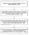
- a method for generating graphical images may be arranged as indicated in FIG. 10 .
- a host computer may broadcast a stream of graphics primitives to a set of rendering processors.
- each rendering processor RP(K) of said set of rendering processors generates a stream of samples in response to the received graphics primitives.
- the samples of the generated stream correspond to sample positions of the subset T K as described above.
- each rendering processor RP(K) adds a dither value D K to a data component (such as red, green, blue or alpha) of each the samples in the generated stream to obtain dithered data components.
- the dither values may have an average value of 1 ⁇ 2 and a dither radius greater than or equal to one.
- each rendering processor RP(K) buffers the dithered data components in an internal frame buffer, and forwards a truncated version of the dithered data components to a corresponding filtering unit.
- the filtering units may be coupled together in a series.
- the filtering units perform a weighted averaging computation in a pipelined fashion on the truncated dithered data components to determine pixel data components.
- the data components are usable to determine at least a portion of a displayable image.
Abstract
Description
T K={(I,J)+(V X(K),V Y(K)): I=0, 1, 2, . . . , M B(K)−1, J=0, 1, 2, . . . , N B(K)−1}
as suggested by
rP=ΣCSrS, (1)
where the summation ranges over each sample S in the filter support region, and where rS is the red sample value of the sample S. In other words, the red component of each sample S in the filter support region is multiplied by the corresponding filter coefficient CS, and the resulting products are summed. Similar weighted summations are performed to determine a green summation value gP and a blue summation value bP for the video pixel P based respectively on the green color components gS and the blue color components bS of the samples:
gP=ΣCSgS, (1′)
bP=ΣCSbS, (1″)
EP=ΣCS. (2)
The summation values may then be multiplied by the reciprocal of EP (or equivalently, divided by EP) to determine normalized pixel values:
R P=(1/E P)*r P (3)
G P=(1/E P)*g P (4)
B P=(1/E P)*b P (5)
CS r(K)=CS r(K−1)+PS r(K)
CS g(K)=CS g(K−1)+PS g(K)
CS b(K)=CS b(K−1)+PS b(K)
CS E(K)=CS E(K−1)+PS E(K),
and transmits the updated cumulative sums to the next filtering unit FU(K+1).
CS r(N FU−1)=CS r(N FU−2)+PS r(N FU−1)
CS g(N FU−1)=CS g(N FU−2)+PS g(N FU−1)
CS b(N FU−1)=CS b(N FU−2)+PS b(N FU−1)
CS E(N FU−1)=CS E(N FU−2)+PS E(N FU−1).
These final cumulative sums are the summation values described above, i.e.,
r P =CS r(N FU−1)
g P =CS g(N FU−1)
b P =CS b(N FU−1)
EP =CS E(N FU−1).
Furthermore, the last filtering unit FU(NFU−1) may be programmably configured to perform the normalizing computations to determine the color components RP, GP and BP of the video pixel P:
R P=(1/E P)*r P
G P=(1/E P)*g P
B P=(1/E P)*b P.
(D S)2=(X S −X P)2+(Y S −Y P)2.
The square radius (DS)2 may be compared to the square radius (Rf)2 of the filter support. If the sample's square radius is less than (or, in a different embodiment, less than or equal to) the filter's square radius, the sample S may be marked as being valid (i.e., inside the filter support). Otherwise, the sample S may be marked as invalid.
The normalized square radius US may be used to access the filter coefficient table for the filter coefficient CS. The filter coefficient table may store filter coefficients indexed by the normalized square radius.
X P −R f <X S <X P +R f and
Y P −R f <Y S <Y P +R f.
Otherwise the sample S may be marked as invalid. Each valid sample may be assigned the same filter weight value (e.g., CS=1). It is noted that any or all of the strict inequalities (<) in the system above may be replaced with permissive inequalities (≦). Various embodiments along these lines are contemplated.
R S ′=R S +D K
G S ′=G S +D K
B S ′=B S +D K. (6)
These additions may be implemented using a programmable pixel shader in the graphics card GC(K). (Any of a variety of modern OEM graphics cards include programmable pixel shaders.) The dithered color values RS′, GS′ and BS′ of the sample S are then buffered and forwarded to the filtering unit FU(K) through the video data port VDP(K) instead of the originally computed color values RS, GS and BS. In the process of buffering and forwarding, the dithered color values RS′, GS′ and BS′ get truncated down to the lower precision values Trn(RS′), Trn(GS′) and Trn(BS′). It is these truncated values Trn(RS′), Trn(GS′) and Trn(BS′) that are output from the video data port VDP(K) in the stream HK and received by the filtering unit FU(K). Thus, the filtering unit FU(K) computes its partial sums based on the truncated color values Trn(RS′), Trn(GS′) and Trn(BS′). The series of filtering units FU(0), FU(1), . . . , FU(NFU−1) compute the color components of a video pixel P by accumulating the partial sums and normalizing the final sum as described above. The dithering operation allows the pixel color components computed by the series of filtering units to more closely approximate the ideal pixel color components which would be obtained from performing the same summation and normalization computations on the original high-precision (i.e., precision P1) sample color components RS, BS and GS.
Claims (23)
Priority Applications (1)
| Application Number | Priority Date | Filing Date | Title |
|---|---|---|---|
| US10/721,634 US7180525B1 (en) | 2003-11-25 | 2003-11-25 | Spatial dithering to overcome limitations in RGB color precision of data interfaces when using OEM graphics cards to do high-quality antialiasing |
Applications Claiming Priority (1)
| Application Number | Priority Date | Filing Date | Title |
|---|---|---|---|
| US10/721,634 US7180525B1 (en) | 2003-11-25 | 2003-11-25 | Spatial dithering to overcome limitations in RGB color precision of data interfaces when using OEM graphics cards to do high-quality antialiasing |
Publications (1)
| Publication Number | Publication Date |
|---|---|
| US7180525B1 true US7180525B1 (en) | 2007-02-20 |
Family
ID=37745000
Family Applications (1)
| Application Number | Title | Priority Date | Filing Date |
|---|---|---|---|
| US10/721,634 Expired - Lifetime US7180525B1 (en) | 2003-11-25 | 2003-11-25 | Spatial dithering to overcome limitations in RGB color precision of data interfaces when using OEM graphics cards to do high-quality antialiasing |
Country Status (1)
| Country | Link |
|---|---|
| US (1) | US7180525B1 (en) |
Cited By (10)
| Publication number | Priority date | Publication date | Assignee | Title |
|---|---|---|---|---|
| US20050231502A1 (en) * | 2004-04-16 | 2005-10-20 | John Harper | High-level program interface for graphics operations |
| US20060146188A1 (en) * | 2002-04-15 | 2006-07-06 | Microsoft Corporation | Methods and Apparatuses for Facilitating Processing of Interlaced Video Images for Progressive Video Displays |
| US20060153476A1 (en) * | 2003-08-01 | 2006-07-13 | Microsoft Corporation | Strategies for Performing Scaling Operations on Image Information |
| US20080252655A1 (en) * | 2007-04-16 | 2008-10-16 | Texas Instruments Incorporated | Techniques for efficient dithering |
| US7451457B2 (en) | 2002-04-15 | 2008-11-11 | Microsoft Corporation | Facilitating interaction between video renderers and graphics device drivers |
| US20090031328A1 (en) * | 2002-04-15 | 2009-01-29 | Microsoft Corporation | Facilitating Interaction Between Video Renderers and Graphics Device Drivers |
| US20090217266A1 (en) * | 2008-02-22 | 2009-08-27 | International Business Machines Corporation | Streaming attachment of hardware accelerators to computer systems |
| US7643675B2 (en) | 2003-08-01 | 2010-01-05 | Microsoft Corporation | Strategies for processing image information using a color information data structure |
| US20110187736A1 (en) * | 2004-04-16 | 2011-08-04 | Apple Inc. | System and Method for Processing Graphics Operations with Graphics Processing Unit |
| US9691118B2 (en) | 2004-04-16 | 2017-06-27 | Apple Inc. | System for optimizing graphics operations |
Citations (10)
| Publication number | Priority date | Publication date | Assignee | Title |
|---|---|---|---|---|
| US5594854A (en) | 1995-03-24 | 1997-01-14 | 3Dlabs Inc. Ltd. | Graphics subsystem with coarse subpixel correction |
| US5598184A (en) | 1992-03-27 | 1997-01-28 | Hewlett-Packard Company | Method and apparatus for improved color recovery in a computer graphics system |
| US5850208A (en) * | 1996-03-15 | 1998-12-15 | Rendition, Inc. | Concurrent dithering and scale correction of pixel color values |
| US6144365A (en) | 1998-04-15 | 2000-11-07 | S3 Incorporated | System and method for performing blending using an over sampling buffer |
| US6154195A (en) * | 1998-05-14 | 2000-11-28 | S3 Incorporated | System and method for performing dithering with a graphics unit having an oversampling buffer |
| US6215913B1 (en) | 1996-01-26 | 2001-04-10 | Texas Instruments Incorporated | Non-monotonic contour diffusion and algorithm |
| US20020005854A1 (en) * | 2000-01-11 | 2002-01-17 | Sun Microsystems, Inc. | Recovering added precision from L-bit samples by dithering the samples prior to an averaging computation |
| US20020018073A1 (en) * | 2000-03-28 | 2002-02-14 | Stradley David J. | Increasing color accuracy |
| US6476824B1 (en) | 1998-08-05 | 2002-11-05 | Mitsubishi Denki Kabushiki Kaisha | Luminance resolution enhancement circuit and display apparatus using same |
| US6661421B1 (en) | 1998-05-21 | 2003-12-09 | Mitsubishi Electric & Electronics Usa, Inc. | Methods for operation of semiconductor memory |
-
2003
- 2003-11-25 US US10/721,634 patent/US7180525B1/en not_active Expired - Lifetime
Patent Citations (10)
| Publication number | Priority date | Publication date | Assignee | Title |
|---|---|---|---|---|
| US5598184A (en) | 1992-03-27 | 1997-01-28 | Hewlett-Packard Company | Method and apparatus for improved color recovery in a computer graphics system |
| US5594854A (en) | 1995-03-24 | 1997-01-14 | 3Dlabs Inc. Ltd. | Graphics subsystem with coarse subpixel correction |
| US6215913B1 (en) | 1996-01-26 | 2001-04-10 | Texas Instruments Incorporated | Non-monotonic contour diffusion and algorithm |
| US5850208A (en) * | 1996-03-15 | 1998-12-15 | Rendition, Inc. | Concurrent dithering and scale correction of pixel color values |
| US6144365A (en) | 1998-04-15 | 2000-11-07 | S3 Incorporated | System and method for performing blending using an over sampling buffer |
| US6154195A (en) * | 1998-05-14 | 2000-11-28 | S3 Incorporated | System and method for performing dithering with a graphics unit having an oversampling buffer |
| US6661421B1 (en) | 1998-05-21 | 2003-12-09 | Mitsubishi Electric & Electronics Usa, Inc. | Methods for operation of semiconductor memory |
| US6476824B1 (en) | 1998-08-05 | 2002-11-05 | Mitsubishi Denki Kabushiki Kaisha | Luminance resolution enhancement circuit and display apparatus using same |
| US20020005854A1 (en) * | 2000-01-11 | 2002-01-17 | Sun Microsystems, Inc. | Recovering added precision from L-bit samples by dithering the samples prior to an averaging computation |
| US20020018073A1 (en) * | 2000-03-28 | 2002-02-14 | Stradley David J. | Increasing color accuracy |
Non-Patent Citations (4)
| Title |
|---|
| "Improving A/D Converter Performance using Dither," (C) 1995 National Semiconductor Corporation, pp. 1-7. |
| Collins, James J., Thomas T. Imhoff, and Peter Grigg, "Noise-enhanced tactile sensation", Journal, Oct. 31, 1996, vol. 383 p. 770, Nature. |
| Gluckman, Bruce J., et al. "Stochastic Resonance in a Neuronal Network from Mammalian Brain", Journal, Nov. 4, 1996, vol. 77, No. 19, pp. 4098-4101, The American Physical Society. |
| Paddock, Bob, "A Guide to online information about: Noise/Chaos/Random Numbers and Linear Feedback Shift Registers," Magazine, Aug. 1999, (C) Circuit Cellar, pp. 1-14. |
Cited By (24)
| Publication number | Priority date | Publication date | Assignee | Title |
|---|---|---|---|---|
| US7876379B2 (en) | 2002-04-15 | 2011-01-25 | Microsoft Corporation | Methods and apparatuses for facilitating processing of interlaced video images for progressive video displays |
| US7451457B2 (en) | 2002-04-15 | 2008-11-11 | Microsoft Corporation | Facilitating interaction between video renderers and graphics device drivers |
| US20090031328A1 (en) * | 2002-04-15 | 2009-01-29 | Microsoft Corporation | Facilitating Interaction Between Video Renderers and Graphics Device Drivers |
| US8176500B2 (en) | 2002-04-15 | 2012-05-08 | Microsoft Corporation | Closing a video stream object |
| US20060146188A1 (en) * | 2002-04-15 | 2006-07-06 | Microsoft Corporation | Methods and Apparatuses for Facilitating Processing of Interlaced Video Images for Progressive Video Displays |
| US20110102672A1 (en) * | 2002-04-15 | 2011-05-05 | Microsoft Corporation | Closing a Video Stream Object |
| US7929754B2 (en) | 2003-08-01 | 2011-04-19 | Microsoft Corporation | Strategies for processing image information using a color information data structure |
| US20060153476A1 (en) * | 2003-08-01 | 2006-07-13 | Microsoft Corporation | Strategies for Performing Scaling Operations on Image Information |
| US7317827B2 (en) | 2003-08-01 | 2008-01-08 | Microsoft Corporation | Strategies for optimally generating pipeline processing code |
| US7400762B2 (en) * | 2003-08-01 | 2008-07-15 | Microsoft Corporation | Strategies for performing scaling operations on image information |
| US20100150441A1 (en) * | 2003-08-01 | 2010-06-17 | Microsoft Corporation | Strategies for Processing Image Information Using a Color Information Data Structure |
| US8428346B2 (en) | 2003-08-01 | 2013-04-23 | Microsoft Corporation | Strategies for processing image information using a color information data structure |
| US7643675B2 (en) | 2003-08-01 | 2010-01-05 | Microsoft Corporation | Strategies for processing image information using a color information data structure |
| US8009176B2 (en) * | 2004-04-16 | 2011-08-30 | Apple Inc. | System and method for processing graphics operations with graphics processing unit |
| US20050231502A1 (en) * | 2004-04-16 | 2005-10-20 | John Harper | High-level program interface for graphics operations |
| US20110187736A1 (en) * | 2004-04-16 | 2011-08-04 | Apple Inc. | System and Method for Processing Graphics Operations with Graphics Processing Unit |
| US10402934B2 (en) | 2004-04-16 | 2019-09-03 | Apple Inc. | System for optimizing graphics operations |
| US8520021B2 (en) | 2004-04-16 | 2013-08-27 | Apple Inc. | System and method for processing graphics operations with graphics processing unit |
| US8704837B2 (en) | 2004-04-16 | 2014-04-22 | Apple Inc. | High-level program interface for graphics operations |
| US9691118B2 (en) | 2004-04-16 | 2017-06-27 | Apple Inc. | System for optimizing graphics operations |
| US7864191B2 (en) * | 2007-04-16 | 2011-01-04 | Texas Instruments Incorporated | Techniques for efficient dithering |
| US20080252655A1 (en) * | 2007-04-16 | 2008-10-16 | Texas Instruments Incorporated | Techniques for efficient dithering |
| US8726289B2 (en) * | 2008-02-22 | 2014-05-13 | International Business Machines Corporation | Streaming attachment of hardware accelerators to computer systems |
| US20090217266A1 (en) * | 2008-02-22 | 2009-08-27 | International Business Machines Corporation | Streaming attachment of hardware accelerators to computer systems |
Similar Documents
| Publication | Publication Date | Title |
|---|---|---|
| EP0525527B1 (en) | Look-up table based gamma and inverse gamma correction for high-resolution frame buffers | |
| US7911487B2 (en) | Methods and systems for sub-pixel rendering with gamma adjustment | |
| US5923316A (en) | Optimized color space conversion | |
| US6894698B2 (en) | Recovering added precision from L-bit samples by dithering the samples prior to an averaging computation | |
| JPH06309146A (en) | Apparatus for conversion of floating-point representation of number into integer representation and method for generation of value of pixel | |
| US7492376B2 (en) | Graphics resampling system and method for use thereof | |
| US20050024380A1 (en) | Method for reducing random access memory of IC in display devices | |
| US7180525B1 (en) | Spatial dithering to overcome limitations in RGB color precision of data interfaces when using OEM graphics cards to do high-quality antialiasing | |
| US6518970B1 (en) | Graphics processing device with integrated programmable synchronization signal generation | |
| KR101340427B1 (en) | Improved memory structures for image processing | |
| CN108074539B (en) | Electronic device, display driver and display data generation method of display panel | |
| US8107756B2 (en) | Digital image tone remapping method and apparatus | |
| US7200283B2 (en) | Apparatus and method for alpha blending of digital images | |
| US6587117B1 (en) | Apparatus and method for adaptive transformation of fractional pixel coordinates for calculating color values | |
| US6188803B1 (en) | Image processing device | |
| US7061504B1 (en) | Method and apparatus for configurable gamma correction in a video graphics circuit | |
| US5265210A (en) | Method and apparatus for plotting pixels to approximate a straight line on a computer display device without substantial irregularities | |
| US6801923B2 (en) | System and method for a single-pass multiple tap filter | |
| JP5106483B2 (en) | Method and apparatus for vertically scaling pixel data | |
| US6720972B2 (en) | Method and apparatus for remapping subpixels for a color display | |
| US20040012614A1 (en) | Scaling apparatus and method | |
| JP3022197B2 (en) | Average luminance detection circuit of pixel structure display device | |
| JP4270795B2 (en) | Method and apparatus for remapping subpixels for color displays | |
| JPH09244572A (en) | Method and device for displaying image, and data transmission method |
Legal Events
| Date | Code | Title | Description |
|---|---|---|---|
| AS | Assignment |
Owner name: SUN MICROSYSTEMS, INC., CALIFORNIA Free format text: ASSIGNMENT OF ASSIGNORS INTEREST;ASSIGNOR:NAEGLE, NATHANIEL DAVID;REEL/FRAME:014750/0567 Effective date: 20031120 |
|
| STCF | Information on status: patent grant |
Free format text: PATENTED CASE |
|
| FPAY | Fee payment |
Year of fee payment: 4 |
|
| FPAY | Fee payment |
Year of fee payment: 8 |
|
| AS | Assignment |
Owner name: ORACLE AMERICA, INC., CALIFORNIA Free format text: MERGER AND CHANGE OF NAME;ASSIGNORS:ORACLE USA, INC.;SUN MICROSYSTEMS, INC.;ORACLE AMERICA, INC.;REEL/FRAME:037302/0719 Effective date: 20100212 |
|
| MAFP | Maintenance fee payment |
Free format text: PAYMENT OF MAINTENANCE FEE, 12TH YEAR, LARGE ENTITY (ORIGINAL EVENT CODE: M1553) Year of fee payment: 12 |