US7178732B1 - Bar code reader with image display system - Google Patents
Bar code reader with image display system Download PDFInfo
- Publication number
- US7178732B1 US7178732B1 US10/983,853 US98385304A US7178732B1 US 7178732 B1 US7178732 B1 US 7178732B1 US 98385304 A US98385304 A US 98385304A US 7178732 B1 US7178732 B1 US 7178732B1
- Authority
- US
- United States
- Prior art keywords
- bar code
- code reader
- display system
- image display
- customer
- Prior art date
- Legal status (The legal status is an assumption and is not a legal conclusion. Google has not performed a legal analysis and makes no representation as to the accuracy of the status listed.)
- Active, expires
Links
- 238000005286 illumination Methods 0.000 claims description 25
- 229920003023 plastic Polymers 0.000 claims description 4
- 230000000007 visual effect Effects 0.000 claims description 4
- 208000032041 Hearing impaired Diseases 0.000 claims description 3
- 239000004973 liquid crystal related substance Substances 0.000 claims description 3
- 239000002985 plastic film Substances 0.000 claims 5
- 230000001737 promoting effect Effects 0.000 claims 1
- 230000008901 benefit Effects 0.000 description 3
- 239000004033 plastic Substances 0.000 description 3
- 238000010586 diagram Methods 0.000 description 2
- 230000003287 optical effect Effects 0.000 description 2
- 229920004142 LEXAN™ Polymers 0.000 description 1
- 238000005530 etching Methods 0.000 description 1
- 238000012986 modification Methods 0.000 description 1
- 230000004048 modification Effects 0.000 description 1
- 238000011017 operating method Methods 0.000 description 1
- 230000001932 seasonal effect Effects 0.000 description 1
- 238000010408 sweeping Methods 0.000 description 1
Images


Classifications
-
- G—PHYSICS
- G06—COMPUTING; CALCULATING OR COUNTING
- G06K—GRAPHICAL DATA READING; PRESENTATION OF DATA; RECORD CARRIERS; HANDLING RECORD CARRIERS
- G06K7/00—Methods or arrangements for sensing record carriers, e.g. for reading patterns
- G06K7/10—Methods or arrangements for sensing record carriers, e.g. for reading patterns by electromagnetic radiation, e.g. optical sensing; by corpuscular radiation
- G06K7/10544—Methods or arrangements for sensing record carriers, e.g. for reading patterns by electromagnetic radiation, e.g. optical sensing; by corpuscular radiation by scanning of the records by radiation in the optical part of the electromagnetic spectrum
- G06K7/10821—Methods or arrangements for sensing record carriers, e.g. for reading patterns by electromagnetic radiation, e.g. optical sensing; by corpuscular radiation by scanning of the records by radiation in the optical part of the electromagnetic spectrum further details of bar or optical code scanning devices
- G06K7/10861—Methods or arrangements for sensing record carriers, e.g. for reading patterns by electromagnetic radiation, e.g. optical sensing; by corpuscular radiation by scanning of the records by radiation in the optical part of the electromagnetic spectrum further details of bar or optical code scanning devices sensing of data fields affixed to objects or articles, e.g. coded labels
Definitions
- the present invention relates to bar code readers and more specifically to a bar code reader with an image display system.
- Bar code readers are well known for their usefulness in retail checkout and inventory control. Some bar code readers have single apertures and other bar code readers have multiple apertures for scanning bar code labels from multiple directions.
- a bar code reader with an image display system is provided.
- the bar code reader includes a housing portion and an image display system in the housing portion.
- An example bar code reader includes a dual-aperture bar code reader with a first housing portion containing a substantially horizontal aperture through which first scanning light beams pass for scanning an item, and a second housing portion vertically extending from a checkout counter containing a substantially vertical aperture through which second scanning light beams pass for scanning the item.
- the second housing portion includes a surface visible to the customer and an image display system in the surface.
- It is another object of the present invention provide a bar code reader with changeable, illuminated, customer specific marketing and branding images.
- It is another object of the present invention provide additional visual feedback for cashiers and hearing impaired customers.
- FIG. 1 is a block diagram of a bar code reader with a first example image illumination system
- FIG. 2 is a perspective view of an example bar code reader including the first example image illumination system
- FIG. 3 is a view of the example bar code reader of FIG. 2 with an exploded view of the first example image illumination system;
- FIG. 4 is a block diagram of a bar code reader with a second example image illumination system.
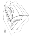
- FIG. 5 is a perspective view of the example bar code reader including the second example image illumination system.
- bar code reader 10 may include an optical bar code reader.
- Bar code reader 10 may include other types of readers besides optical readers, such as image capturing bar code readers with charge coupled device cameras.
- bar code reader includes laser 12 , mirrored spinner 14 , pattern mirrors 18 , collector 22 , detector 24 , control circuitry 26 , and image display system 28 .
- Laser 12 includes a laser diode, a focusing lens or lenses, and a collimating aperture for producing a laser beam.
- Mirrored spinner 14 has a plurality of planoreflective mirrored facets for sweeping the laser beam across pattern mirrors 16 to produce scanning beams. Mirrored spinner 14 also directs light reflected from item 18 towards collector 22 . Mirrored spinner is rotated by motor 15 .
- Pattern mirrors 18 produce a plurality of scan lines for scanning bar code 20 on item 18 . Pattern mirrors receive the light reflected from item 18 and direct it back towards mirrored spinner 14 .
- Collector 22 collects the light reflected from item 18 and directs it towards detector 24 .
- Detector 24 generates electrical signals representing the intensity of the reflected light.
- Control circuitry 26 controls operation of laser 12 and motor 15 , and decodes bar code information from the electrical signals produced by detector 24 .
- bar code reader 10 includes an integrated image display system 28 .
- image display system may include a printed or embossed image 30 .
- Image display system 28 may further include an illumination device 31 for illuminating the printed or embossed image 30 .
- Control circuitry 26 may control image illumination device 31 .
- image illumination device 31 operates independently of control circuitry 26 .
- Image illumination device 31 may include a backlight.
- image display system 28 may instead include a computer display for displaying images provided by a computer.
- the images of image display system 28 may include a store brand, a marketing slogan, advertisement, or any other image for the purpose of conveying information or suggestions to a customer at a checkout counter and adjacent bar code reader 10 .
- control circuitry 26 may activate image illumination device 31 following each successful reading of a bar code label.
- Image 30 may be visible or not visible when image illumination device is deactivated.
- image illumination device 31 may be in a dim state and flash brighter following each successful read.
- the flashing may be single and or multiple flashes, or flashing with a designed pattern. Either way, these operating methods have the added advantage of providing additional visual feedback to cashiers and hearing impaired customers.
- Image illumination device 31 may also be tied into servicing of bar code reader 10 to provide diagnostic feedback to operators and service technicians.
- an example bar code reader 10 including a first example image display system 28 is shown.
- Example bar code reader 10 includes a multi-aperture bar code reader having a first portion 32 containing a substantially horizontal aperture 34 and second portion 36 containing a substantially vertical aperture 38 .
- First portion 32 is mounted within checkout counter 40
- second portion 36 extends above checkout counter 40 .
- Bar code reader 10 may alternatively include a single-aperture bar code reader, such as a vertically mounted presentation scanner.
- Image display system 28 may be located within any surface of second portion 36 . In the illustrated example, image display system 28 is located in aperture 48 of top surface 42 . Another suitable location is in customer side surface 44 . Image display system 28 is displaying a customer logo 46 .
- the first example illumination system 28 further includes image illumination device 31 , strip 52 , and cover 54 .
- Image illumination device 31 is located in the approximate center of top surface 42 .
- image illumination device 31 may include edge lighting with etching glow.
- Strip 52 rests on image illumination device 31 .
- Strip 52 may be made of plastic, such as a Lexan® plastic from General Electric, and may be semi-transparent.
- Strip 52 includes a printed or embossed image 30 of customer logo 46 . Customer logo 46 may be visible or not visible without illumination.
- Cover 54 may also be made of plastic and may be transparent. Cover 54 snaps into a detent 56 in top surface 42 around perimeter 58 so as to retain strip 52 . Cover 54 may be easily removed from detent 56 in order to replace strip 52 with a different strip 52 containing a different image, such as a seasonal promotion.
- bar code reader 10 includes a second example image display system 28 .
- image display system 28 includes a computer display 60 .
- Computer display 60 may include a liquid crystal display (LCD).
- Computer display 60 is mounted in top surface 42 of bar code reader 10 , but may be mounted elsewhere in portion 36 .
- Computer display 60 may be controlled by point-of-sale terminal 62 through a separate cable to bar code reader 10 .
- Point-of-sale terminal 62 may store electronic images 64 for display by computer display 60 .
- point-of-sale terminal 62 may execute image control software 66 which causes an operator selected electronic image 64 or a sequence of electronic images 64 to be displayed by computer display 60 so long as point-of-sale terminal 62 is in operation.
- bar code reader 10 with image display system 28 allows store operators to more effectively promote themselves and their products.
Landscapes
- Physics & Mathematics (AREA)
- Electromagnetism (AREA)
- Engineering & Computer Science (AREA)
- Health & Medical Sciences (AREA)
- General Health & Medical Sciences (AREA)
- Toxicology (AREA)
- Artificial Intelligence (AREA)
- Computer Vision & Pattern Recognition (AREA)
- General Physics & Mathematics (AREA)
- Theoretical Computer Science (AREA)
- Cash Registers Or Receiving Machines (AREA)
Abstract
Description
Claims (17)
Priority Applications (1)
| Application Number | Priority Date | Filing Date | Title |
|---|---|---|---|
| US10/983,853 US7178732B1 (en) | 2004-11-08 | 2004-11-08 | Bar code reader with image display system |
Applications Claiming Priority (1)
| Application Number | Priority Date | Filing Date | Title |
|---|---|---|---|
| US10/983,853 US7178732B1 (en) | 2004-11-08 | 2004-11-08 | Bar code reader with image display system |
Publications (1)
| Publication Number | Publication Date |
|---|---|
| US7178732B1 true US7178732B1 (en) | 2007-02-20 |
Family
ID=37744846
Family Applications (1)
| Application Number | Title | Priority Date | Filing Date |
|---|---|---|---|
| US10/983,853 Active 2024-12-10 US7178732B1 (en) | 2004-11-08 | 2004-11-08 | Bar code reader with image display system |
Country Status (1)
| Country | Link |
|---|---|
| US (1) | US7178732B1 (en) |
Cited By (4)
| Publication number | Priority date | Publication date | Assignee | Title |
|---|---|---|---|---|
| US20060266840A1 (en) * | 2005-05-31 | 2006-11-30 | Symbol Technologies, Inc. | Feedback mechanism for scanner devices |
| US20080121717A1 (en) * | 2006-09-21 | 2008-05-29 | Gregerson David L | Barcode scanner with configurable video modes |
| US20090308928A1 (en) * | 2008-06-11 | 2009-12-17 | Janani Janakiraman | System to improve communication using a laser bar code scanner and associated methods |
| US20110108628A1 (en) * | 2009-11-12 | 2011-05-12 | Christopher Brock | Method and apparatus for projecting illumination patterns from barcode readers |
Citations (11)
| Publication number | Priority date | Publication date | Assignee | Title |
|---|---|---|---|---|
| US4575623A (en) * | 1985-01-10 | 1986-03-11 | Ncr Corporation | Optical code scanner and display |
| US6213394B1 (en) * | 1999-06-14 | 2001-04-10 | Industrial Electronic Engineers, Inc. | Visual system for, and method of, displaying graphics and alphanumeric information |
| US20020010496A1 (en) * | 2000-05-26 | 2002-01-24 | Greenberg Robert J. | Video processing methods for improving visual acuity and/or perceived image resolution |
| US20020071076A1 (en) * | 2000-08-16 | 2002-06-13 | Webb Richard M. | Scannable barcode display and methods for using the same |
| US20030010825A1 (en) * | 2000-04-18 | 2003-01-16 | Mark Schmidt | Point of sale (POS) based bar code reading system with integrated internet-enabled customer-kiosk terminal |
| US6598791B2 (en) * | 2001-01-19 | 2003-07-29 | Psc Scanning, Inc. | Self-checkout system and method including item buffer for item security verification |
| US20030201326A1 (en) * | 1992-07-14 | 2003-10-30 | Psc Scanning, Inc. | Multiple plane scanning system for data reading applications |
| US20030205620A1 (en) * | 2002-05-03 | 2003-11-06 | Sung Byun | Point of sale (POS) based bar code reading systems having light-pipe based bar code read indication subsystems integrated therein |
| US20040000591A1 (en) * | 2002-06-28 | 2004-01-01 | Collins Donald A. | Checkout device including integrated barcode reader and EAS system |
| US6854655B2 (en) * | 2001-04-03 | 2005-02-15 | Symbol Technologies, Inc. | Two window optical scanner |
| US6974083B1 (en) * | 2004-07-23 | 2005-12-13 | Symbol Technologies, Inc. | Point-of-transaction workstation for electro-optically reading one-dimensional indicia, including image capture of two-dimensional targets |
-
2004
- 2004-11-08 US US10/983,853 patent/US7178732B1/en active Active
Patent Citations (11)
| Publication number | Priority date | Publication date | Assignee | Title |
|---|---|---|---|---|
| US4575623A (en) * | 1985-01-10 | 1986-03-11 | Ncr Corporation | Optical code scanner and display |
| US20030201326A1 (en) * | 1992-07-14 | 2003-10-30 | Psc Scanning, Inc. | Multiple plane scanning system for data reading applications |
| US6213394B1 (en) * | 1999-06-14 | 2001-04-10 | Industrial Electronic Engineers, Inc. | Visual system for, and method of, displaying graphics and alphanumeric information |
| US20030010825A1 (en) * | 2000-04-18 | 2003-01-16 | Mark Schmidt | Point of sale (POS) based bar code reading system with integrated internet-enabled customer-kiosk terminal |
| US20020010496A1 (en) * | 2000-05-26 | 2002-01-24 | Greenberg Robert J. | Video processing methods for improving visual acuity and/or perceived image resolution |
| US20020071076A1 (en) * | 2000-08-16 | 2002-06-13 | Webb Richard M. | Scannable barcode display and methods for using the same |
| US6598791B2 (en) * | 2001-01-19 | 2003-07-29 | Psc Scanning, Inc. | Self-checkout system and method including item buffer for item security verification |
| US6854655B2 (en) * | 2001-04-03 | 2005-02-15 | Symbol Technologies, Inc. | Two window optical scanner |
| US20030205620A1 (en) * | 2002-05-03 | 2003-11-06 | Sung Byun | Point of sale (POS) based bar code reading systems having light-pipe based bar code read indication subsystems integrated therein |
| US20040000591A1 (en) * | 2002-06-28 | 2004-01-01 | Collins Donald A. | Checkout device including integrated barcode reader and EAS system |
| US6974083B1 (en) * | 2004-07-23 | 2005-12-13 | Symbol Technologies, Inc. | Point-of-transaction workstation for electro-optically reading one-dimensional indicia, including image capture of two-dimensional targets |
Cited By (7)
| Publication number | Priority date | Publication date | Assignee | Title |
|---|---|---|---|---|
| US20060266840A1 (en) * | 2005-05-31 | 2006-11-30 | Symbol Technologies, Inc. | Feedback mechanism for scanner devices |
| US7331524B2 (en) * | 2005-05-31 | 2008-02-19 | Symbol Technologies, Inc. | Feedback mechanism for scanner devices |
| US20080121717A1 (en) * | 2006-09-21 | 2008-05-29 | Gregerson David L | Barcode scanner with configurable video modes |
| US7380719B1 (en) * | 2006-09-21 | 2008-06-03 | Ncr Corporation | Barcode scanner with configurable video modes |
| US20090308928A1 (en) * | 2008-06-11 | 2009-12-17 | Janani Janakiraman | System to improve communication using a laser bar code scanner and associated methods |
| US20110108628A1 (en) * | 2009-11-12 | 2011-05-12 | Christopher Brock | Method and apparatus for projecting illumination patterns from barcode readers |
| US8740084B2 (en) * | 2009-11-12 | 2014-06-03 | Symbol Technologies, Inc. | Method and apparatus for projecting illumination patterns from barcode readers |
Similar Documents
| Publication | Publication Date | Title |
|---|---|---|
| US8479997B2 (en) | Optical scanner with customer interface | |
| EP2168075B1 (en) | Imaging reader with plural solid-state imagers for electro-optically reading indicia | |
| US7597263B2 (en) | Imaging reader with target proximity sensor | |
| JP4321782B2 (en) | Display shelf | |
| EP2756448B1 (en) | Apparatus for and method of reading printed and electronic codes | |
| US20090218405A1 (en) | Imaging System for Reading Mobile Device Indicia | |
| US8613393B2 (en) | Optical scanner with customer interface | |
| US7850068B2 (en) | Commodity information acquisition and display apparatus | |
| US7717235B2 (en) | Convertible point-of-sale checkout terminal | |
| US7690575B2 (en) | Imaging reader with adaptive illumination and adaptive resolution | |
| CN102096796A (en) | Scanner and commodity code reading device | |
| US20080035732A1 (en) | Uniform illumination without specular reflection in imaging reader | |
| US20030205620A1 (en) | Point of sale (POS) based bar code reading systems having light-pipe based bar code read indication subsystems integrated therein | |
| GB2510533B (en) | Apparatus for and method of uniformly illuminating fields of view in a point-of-transaction workstation | |
| US20120273572A1 (en) | Point-of-transaction workstation for and method of imaging indicia over full coverage scan zone occupied by unskewed subfields of view | |
| US8002184B1 (en) | Bi-optical imaging point-of-transaction workstation with recessed upright window | |
| US5854474A (en) | Electronic sign having automatic price display | |
| JP6981002B2 (en) | Display shelves, information processing equipment, programs and display shelf systems | |
| US7178732B1 (en) | Bar code reader with image display system | |
| US20080296388A1 (en) | Compact, ergonomic imaging reader and method | |
| US20080030874A1 (en) | Negative spherical aberration component-based imaging lens assembly in imaging reader | |
| US20080035733A1 (en) | Illumination without hot spots in field of view of imaging reader | |
| US7445154B2 (en) | Imaging reader with folded image capture path and direct illumination path | |
| US20080023549A1 (en) | Axicon-based imaging lens assembly in imaging reader | |
| RU211334U1 (en) | STATIONARY OPTICAL SCANNER |
Legal Events
| Date | Code | Title | Description |
|---|---|---|---|
| AS | Assignment |
Owner name: NCR CORPORATION, OHIO Free format text: ASSIGNMENT OF ASSIGNORS INTEREST;ASSIGNORS:BARRON, PETER B.;GREGERSON, DAVID L.;WILSON, JOHN E.;REEL/FRAME:016394/0642 Effective date: 20040224 |
|
| STCF | Information on status: patent grant |
Free format text: PATENTED CASE |
|
| FPAY | Fee payment |
Year of fee payment: 4 |
|
| AS | Assignment |
Owner name: JPMORGAN CHASE BANK, N.A., AS ADMINISTRATIVE AGENT, ILLINOIS Free format text: SECURITY AGREEMENT;ASSIGNORS:NCR CORPORATION;NCR INTERNATIONAL, INC.;REEL/FRAME:032034/0010 Effective date: 20140106 Owner name: JPMORGAN CHASE BANK, N.A., AS ADMINISTRATIVE AGENT Free format text: SECURITY AGREEMENT;ASSIGNORS:NCR CORPORATION;NCR INTERNATIONAL, INC.;REEL/FRAME:032034/0010 Effective date: 20140106 |
|
| FPAY | Fee payment |
Year of fee payment: 8 |
|
| AS | Assignment |
Owner name: JPMORGAN CHASE BANK, N.A., ILLINOIS Free format text: SECURITY AGREEMENT;ASSIGNORS:NCR CORPORATION;NCR INTERNATIONAL, INC.;REEL/FRAME:038646/0001 Effective date: 20160331 |
|
| MAFP | Maintenance fee payment |
Free format text: PAYMENT OF MAINTENANCE FEE, 12TH YEAR, LARGE ENTITY (ORIGINAL EVENT CODE: M1553); ENTITY STATUS OF PATENT OWNER: LARGE ENTITY Year of fee payment: 12 |
|
| AS | Assignment |
Owner name: NCR VOYIX CORPORATION, GEORGIA Free format text: RELEASE OF PATENT SECURITY INTEREST;ASSIGNOR:JPMORGAN CHASE BANK, N.A., AS ADMINISTRATIVE AGENT;REEL/FRAME:065346/0531 Effective date: 20231016 Owner name: BANK OF AMERICA, N.A., AS ADMINISTRATIVE AGENT, NORTH CAROLINA Free format text: SECURITY INTEREST;ASSIGNOR:NCR VOYIX CORPORATION;REEL/FRAME:065346/0168 Effective date: 20231016 |
|
| AS | Assignment |
Owner name: NCR VOYIX CORPORATION, GEORGIA Free format text: CHANGE OF NAME;ASSIGNOR:NCR CORPORATION;REEL/FRAME:065820/0704 Effective date: 20231013 |