US7167419B2 - Beverage brewer timer - Google Patents
Beverage brewer timer Download PDFInfo
- Publication number
- US7167419B2 US7167419B2 US10/803,840 US80384004A US7167419B2 US 7167419 B2 US7167419 B2 US 7167419B2 US 80384004 A US80384004 A US 80384004A US 7167419 B2 US7167419 B2 US 7167419B2
- Authority
- US
- United States
- Prior art keywords
- timer
- clamps
- attached
- beverage
- indicating
- Prior art date
- Legal status (The legal status is an assumption and is not a legal conclusion. Google has not performed a legal analysis and makes no representation as to the accuracy of the status listed.)
- Expired - Fee Related, expires
Links
Images


Classifications
-
- G—PHYSICS
- G04—HOROLOGY
- G04F—TIME-INTERVAL MEASURING
- G04F1/00—Apparatus which can be set and started to measure-off predetermined or adjustably-fixed time intervals without driving mechanisms, e.g. egg timers
- G04F1/005—Apparatus which can be set and started to measure-off predetermined or adjustably-fixed time intervals without driving mechanisms, e.g. egg timers using electronic timing, e.g. counting means
-
- A—HUMAN NECESSITIES
- A47—FURNITURE; DOMESTIC ARTICLES OR APPLIANCES; COFFEE MILLS; SPICE MILLS; SUCTION CLEANERS IN GENERAL
- A47J—KITCHEN EQUIPMENT; COFFEE MILLS; SPICE MILLS; APPARATUS FOR MAKING BEVERAGES
- A47J31/00—Apparatus for making beverages
- A47J31/44—Parts or details or accessories of beverage-making apparatus
- A47J31/52—Alarm-clock-controlled mechanisms for coffee- or tea-making apparatus ; Timers for coffee- or tea-making apparatus; Electronic control devices for coffee- or tea-making apparatus
-
- Y—GENERAL TAGGING OF NEW TECHNOLOGICAL DEVELOPMENTS; GENERAL TAGGING OF CROSS-SECTIONAL TECHNOLOGIES SPANNING OVER SEVERAL SECTIONS OF THE IPC; TECHNICAL SUBJECTS COVERED BY FORMER USPC CROSS-REFERENCE ART COLLECTIONS [XRACs] AND DIGESTS
- Y10—TECHNICAL SUBJECTS COVERED BY FORMER USPC
- Y10S—TECHNICAL SUBJECTS COVERED BY FORMER USPC CROSS-REFERENCE ART COLLECTIONS [XRACs] AND DIGESTS
- Y10S224/00—Package and article carriers
- Y10S224/903—Holder for timepiece not carried on wrist
-
- Y—GENERAL TAGGING OF NEW TECHNOLOGICAL DEVELOPMENTS; GENERAL TAGGING OF CROSS-SECTIONAL TECHNOLOGIES SPANNING OVER SEVERAL SECTIONS OF THE IPC; TECHNICAL SUBJECTS COVERED BY FORMER USPC CROSS-REFERENCE ART COLLECTIONS [XRACs] AND DIGESTS
- Y10—TECHNICAL SUBJECTS COVERED BY FORMER USPC
- Y10T—TECHNICAL SUBJECTS COVERED BY FORMER US CLASSIFICATION
- Y10T24/00—Buckles, buttons, clasps, etc.
- Y10T24/44—Clasp, clip, support-clamp, or required component thereof
- Y10T24/44291—Clasp, clip, support-clamp, or required component thereof including pivoted gripping member
Definitions
- the invention relates to the field of electronic timers. More specifically, the invention relates to electronic timers for use for determining when a beverage, particularly brewed coffee, is no longer fresh.
- timers are generally known. However, in order to identify a particular timer with a particular beverage container one has to exercise the mental capacity to associate the timers with the beverage container. This can prove particularly difficult when one is performing a variety of tasks that also require a person's attention and the number of beverage containers and timers is large. While the timers could be placed in a physical location near the beverage container, this causes problems if the beverage container is to be heated, such as in the case of coffee, or if the availability of space around the beverage container is at a minimum. Therefore, there is a need for a timer for a beverage container that can be easily associated with the beverage container such that one can easily identify when the beverage contained within the container is no longer fresh.
- a timer for indicating when a beverage within a beverage container is considered no longer fresh.
- the timer comprises a timer body and a clip.
- the timer body contains electronic circuitry adapted to display a time remaining before the beverage is no longer fresh.
- the timer body further includes two L or other shaped lugs spaced apart from one another.
- the clip comprises two timer clamps attached to one another and a central retainer. Each timer clamp has a first end and a second end. The first end of each of the timer clamps is resiliently biased in a direction away from the other.
- the central retainer further comprises a lug adapted to be attached to the L-shaped flanges of the timer body.
- the second end of the timer clamps are adapted to be easily attached to a beverage container, the clamps can be applied directly to the timer, as noted, and particularly can be applied to the vertical level indicator, which frequently incorporates the amount of beverage remaining within the decanter, and which normally are of tubular configuration.
- the timer clamp of this invention can be biased directly onto that tube, to readily display the remaining time.
- the timer comprises a timer body and a clip.
- the timer body contains electronic circuitry adapted to display a time remaining before the beverage is no longer fresh.
- the clip comprises two timer clamps attached to one another and a central retainer. Each clamp has a first end and a second end. The first end of the timer clamps is resiliently biased in a direction away from one another.
- the second end of each of the timer clamps comprises an extension potion, a generally U-shaped clamping portion attached to the extension portion and an inwardly turned retainer portion attached to the clamping portion.
- FIG. 1 is a front view of a timer according to the present invention
- FIG. 2 is a rear view of a timer according to the present invention.
- FIG. 3 is a side view of a timer according to the present invention.
- FIG. 4 is a front view of a clip for a timer according to the present invention.
- FIG. 5 is a bottom view of a clip for a timer according to the present invention.
- FIG. 6 is a top view of a clip for a timer according to the present invention.
- FIG. 7 is a side view of a clip for a timer according to the present invention.
- FIG. 8 is a top view of a timer body for a timer according to the present invention.
- FIG. 9 is a rear view of a timer body for a timer according to the present invention.
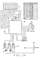
- FIG. 10 is a circuit diagram of a timer according to the present invention.
- FIG. 11 is a block diagram disclosing the electronic components that are utilized in conjunction with the assembly of the beverage brewer timer of this invention.
- the present invention comprises a timer 10 comprising a timer body 12 and a clip 13 comprising pair of timer clamps 14 , 16 .
- the timer clamps 14 , 16 each comprise a first end 18 , 20 and second end 22 , 24 .
- Each second end 22 , 24 comprises an extension portion 26 , 28 attached to each first end 14 , 16 .
- Attached to each extension portion 26 , 28 is a generally U-shaped clamping portion 30 , 32 .
- attached to each clamping portion 30 , 32 is an inwardly formed retainer portion 34 , 36 .
- Each clamping portion 30 , 32 defines an attachment surface 38 , 40 which is formed to fit the handle of a beverage container, particularly a coffee pot. As can be seen in FIG. 3 , the clamping portion 30 , 32 and the retainer portion 34 , 36 are elongated with respect to the remaining portions of the timer clamps 14 , 16 .
- a central retainer 42 attached to the timer body 12 employs an attachment pin 44 to retain the timer clamps 14 , 16 to the central retainer 42 .
- the pin 44 extends through interdigitated flanges 46 alternately extending from the timer clamps 14 , 16 .
- the timer clamps 14 , 16 are rotatingly mounted about the pin 44 to the central retainer 42 .
- the timer clamps 14 , 16 are resiliently biased by springs 48 , 50 such that the second ends 22 , 24 of the clamps 14 , 16 are biased toward one another.
- the lug 52 extends from a side of the central retainer 42 adjacent the timer body 12 .
- the lug 52 comprises a narrowed portion 54 and a widened portion 56 .
- the widened portion 56 defines two slits 58 , 60 to create two resilient legs 62 , 64 having outwardly extending feet 66 , 68 .
- the central retainer 42 comprises two stops 79 , 72 attached to the narrowed portion 54 .
- a rear portion of the timer body 12 comprises two L-shaped flanges 74 , 76 .
- an electronic circuit for performing the timer function is housed within the timer body 12 .
- the circuit generally comprises an LCD control chip including a timer function 78 , an LCD display 80 , a reset switch 82 two LED lights 84 , 86 , and a buzzer 88 .
- Other parts which make up the electrical circuit can be readily identified and understood by one of ordinary skill in the art.
- DIP switches K 3 through K 6 can be set to vary the time from which the timer counts down.
- FIG. 11 shows a block diagram, and herein furnishes a general description, for the various circuitry components that are embodied within the beverage brewer timer of this invention.
- block diagram at 90 , includes a built-in 8-bit RISC processor, at 92 .
- the circuitry also includes a 64-byte scram processor, as at 94 . It is operatively associated with a 4K-byte ROM, or read-only memory 96 .
- the circuitry also includes a built-in RC osculater.
- the circuitry includes what is identified as a watch dog mode (1 Hz or 0.5 Hz).
- the circuitry includes one 8-bit timer 98 .
- the circuitry has a low operating voltage range, between 1.2 v–1.7 v. It operates off rather low stand-by current, in the stand-by mode: ISTBY>1 A.
- It includes an LCD matrix, for read-out purposes, which includes, for example, 19–16 segments, four commons, in configuration, as noted at 100 .
- the circuit board includes 10 general I/O pins, identified by various segments 16 , 17 , 18 , as defined, and as generally noted at 102 .
- the LCDs are generally identified as one-half, one-third bias, one-half, one-third, one-fourth duty. It provides 5 INT sources, for connection.
- the circuitry provides a wake-up source: such as key input, 2 Hz, 16 Hz, and timer.
- various of the segments providing connecting points at the bottom of the shown block diagram may incorporate a mask option for the IOAB7-5.
- the masked option can be defined as 1 I/O for one segment. This provides a description of the block diagram, as shown in the identified figure.
- the LED's 84 , 86 are visible as well as the LCD display 80 and the reset button 82 .
- the present invention is assembled by attaching the L-shaped flanges 74 , 76 to the lug 52 of the timer body 12 by resilient deflecting the legs 62 , 64 inwardly so that the feet 66 , 68 will fit between the L-shaped flanges 74 , 76 of the timer body 12 .
- the timer body 12 is then positioned with respect to the lug 52 such that the L-shaped flanges 74 , 76 of the timer body 12 are captured on the lug 52 between the feet 66 , 68 and the stops 70 , 72 .
- the timer 10 is operated by forcing the first ends 18 , 20 of each timer clamp 14 , 16 toward one another and placing the clip 13 upon a handle of a beverage container.
- the reset button 82 is depressed by the user to start a countdown function of the electrical circuit. While the timer counts down, the current time remaining is displayed upon the LCD display 80 and the green LED 84 flashes to show that the timer is active.
- the buzzer 88 is activated for a predetermined period of time and the red LED 86 is activated for a predetermined period of time. The user is thereby notified that the beverage within the container is no longer fresh and should be discarded.
Landscapes
- Engineering & Computer Science (AREA)
- Food Science & Technology (AREA)
- Physics & Mathematics (AREA)
- General Physics & Mathematics (AREA)
- Measurement Of Predetermined Time Intervals (AREA)
Abstract
Description
| Countdown | ||||
| Time | ||||
| K6 | K5 | K4 | K3 | (hrs) |
| 0 | 0 | 0 | 0 | 0:20 |
| 0 | 0 | 0 | 1 | 0:30 |
| 0 | 0 | 1 | 0 | 0:45 |
| 0 | 0 | 1 | 1 | 1:00 |
| 0 | 1 | 0 | 0 | 1:15 |
| 0 | 1 | 0 | 1 | 1:30 |
| 0 | 1 | 1 | 0 | 2:00 |
| 0 | 1 | 1 | 1 | 2:30 |
| 1 | 0 | 0 | 0 | 3:00 |
| 1 | 0 | 0 | 1 | 4:00 |
Claims (13)
Priority Applications (1)
| Application Number | Priority Date | Filing Date | Title |
|---|---|---|---|
| US10/803,840 US7167419B2 (en) | 2004-03-17 | 2004-03-17 | Beverage brewer timer |
Applications Claiming Priority (1)
| Application Number | Priority Date | Filing Date | Title |
|---|---|---|---|
| US10/803,840 US7167419B2 (en) | 2004-03-17 | 2004-03-17 | Beverage brewer timer |
Publications (2)
| Publication Number | Publication Date |
|---|---|
| US20050207282A1 US20050207282A1 (en) | 2005-09-22 |
| US7167419B2 true US7167419B2 (en) | 2007-01-23 |
Family
ID=34986125
Family Applications (1)
| Application Number | Title | Priority Date | Filing Date |
|---|---|---|---|
| US10/803,840 Expired - Fee Related US7167419B2 (en) | 2004-03-17 | 2004-03-17 | Beverage brewer timer |
Country Status (1)
| Country | Link |
|---|---|
| US (1) | US7167419B2 (en) |
Cited By (10)
| Publication number | Priority date | Publication date | Assignee | Title |
|---|---|---|---|---|
| WO2004002050A1 (en) | 2002-06-21 | 2003-12-31 | Thomson Licensing S.A. | A fault-tolerant broadcast router |
| US20080022858A1 (en) * | 2006-07-31 | 2008-01-31 | Jan Murtagh | Beverage freshness indicator |
| US20080232199A1 (en) * | 2007-03-23 | 2008-09-25 | Leslie Shafton | Time Management Device |
| US20120240862A1 (en) * | 2011-03-21 | 2012-09-27 | Timothy Edwards | Animal feeding reminder system |
| US8397626B2 (en) | 2010-01-29 | 2013-03-19 | Bernard Winkler | Height adjustable beverage brewer |
| US20150378314A1 (en) * | 2013-05-29 | 2015-12-31 | Sakai Display Products Corporation | Timer Device and Time Measurement System |
| US20160091866A1 (en) * | 2014-09-30 | 2016-03-31 | Jersa Iii Michael Joseph | Smart clip |
| USD756806S1 (en) * | 2014-10-11 | 2016-05-24 | Brightfire Technologies Inc. | Cooking timer |
| US20170095108A1 (en) * | 2015-10-05 | 2017-04-06 | Grindmaster Corporation | Beverage brewer with adjustable shelf |
| US20170099824A1 (en) * | 2015-10-13 | 2017-04-13 | Roy Orland Manasco, SR. | Fish Strike Indicator |
Families Citing this family (5)
| Publication number | Priority date | Publication date | Assignee | Title |
|---|---|---|---|---|
| US7874243B2 (en) * | 2007-04-12 | 2011-01-25 | Woods Charles A | Beverage freshness monitoring system and method |
| US20150241849A1 (en) * | 2013-11-15 | 2015-08-27 | Alex Jeffry Wessler | Methods for improved timing of devices |
| GB201603993D0 (en) * | 2016-03-08 | 2016-04-20 | First Hand Learning Ltd | Timer apparatus |
| US20170270326A1 (en) * | 2016-03-18 | 2017-09-21 | Iconex Llc | Band/tag with integrated status and tracking |
| WO2018039735A1 (en) * | 2016-09-02 | 2018-03-08 | Byron Tours Pty Ltd | Illuminating notification system |
Citations (8)
| Publication number | Priority date | Publication date | Assignee | Title |
|---|---|---|---|---|
| US2551515A (en) * | 1947-11-03 | 1951-05-01 | Francis A Newton | Watch holding device for belts |
| US3456262A (en) * | 1967-09-15 | 1969-07-15 | Hercules Clip Corp | Clamping device |
| US4362402A (en) * | 1979-07-20 | 1982-12-07 | Vdo Adolf Schindling Ag | Clock with a holder |
| US4705408A (en) * | 1986-04-01 | 1987-11-10 | Altop S.A. | Watch mounted on a clip |
| US5802677A (en) * | 1996-11-06 | 1998-09-08 | Lilly Industries (Usa), Inc. | Bag closure clip |
| US20010036129A1 (en) * | 2000-03-15 | 2001-11-01 | Carr Raymond Alan | Timing device to warn refrigerated product expiration |
| US6545592B2 (en) * | 1998-09-28 | 2003-04-08 | Steven L. Weiner | Medication reminder device |
| US20030156500A1 (en) * | 2002-02-21 | 2003-08-21 | Popowich Lisa B. | Watch |
-
2004
- 2004-03-17 US US10/803,840 patent/US7167419B2/en not_active Expired - Fee Related
Patent Citations (8)
| Publication number | Priority date | Publication date | Assignee | Title |
|---|---|---|---|---|
| US2551515A (en) * | 1947-11-03 | 1951-05-01 | Francis A Newton | Watch holding device for belts |
| US3456262A (en) * | 1967-09-15 | 1969-07-15 | Hercules Clip Corp | Clamping device |
| US4362402A (en) * | 1979-07-20 | 1982-12-07 | Vdo Adolf Schindling Ag | Clock with a holder |
| US4705408A (en) * | 1986-04-01 | 1987-11-10 | Altop S.A. | Watch mounted on a clip |
| US5802677A (en) * | 1996-11-06 | 1998-09-08 | Lilly Industries (Usa), Inc. | Bag closure clip |
| US6545592B2 (en) * | 1998-09-28 | 2003-04-08 | Steven L. Weiner | Medication reminder device |
| US20010036129A1 (en) * | 2000-03-15 | 2001-11-01 | Carr Raymond Alan | Timing device to warn refrigerated product expiration |
| US20030156500A1 (en) * | 2002-02-21 | 2003-08-21 | Popowich Lisa B. | Watch |
Cited By (14)
| Publication number | Priority date | Publication date | Assignee | Title |
|---|---|---|---|---|
| WO2004002050A1 (en) | 2002-06-21 | 2003-12-31 | Thomson Licensing S.A. | A fault-tolerant broadcast router |
| US20080022858A1 (en) * | 2006-07-31 | 2008-01-31 | Jan Murtagh | Beverage freshness indicator |
| US20080232199A1 (en) * | 2007-03-23 | 2008-09-25 | Leslie Shafton | Time Management Device |
| US8397626B2 (en) | 2010-01-29 | 2013-03-19 | Bernard Winkler | Height adjustable beverage brewer |
| US20120240862A1 (en) * | 2011-03-21 | 2012-09-27 | Timothy Edwards | Animal feeding reminder system |
| US8453592B2 (en) * | 2011-03-21 | 2013-06-04 | Timothy Edwards | Animal feeding reminder system |
| US20150378314A1 (en) * | 2013-05-29 | 2015-12-31 | Sakai Display Products Corporation | Timer Device and Time Measurement System |
| US20160091866A1 (en) * | 2014-09-30 | 2016-03-31 | Jersa Iii Michael Joseph | Smart clip |
| US9597918B2 (en) * | 2014-09-30 | 2017-03-21 | Michael Joseph Jersa, III | Smart clip |
| US20170146957A1 (en) * | 2014-09-30 | 2017-05-25 | Jersa Iii Michael Joseph | Smart clip |
| US9766591B2 (en) * | 2014-09-30 | 2017-09-19 | Michael Joseph Jersa, III | Smart clip |
| USD756806S1 (en) * | 2014-10-11 | 2016-05-24 | Brightfire Technologies Inc. | Cooking timer |
| US20170095108A1 (en) * | 2015-10-05 | 2017-04-06 | Grindmaster Corporation | Beverage brewer with adjustable shelf |
| US20170099824A1 (en) * | 2015-10-13 | 2017-04-13 | Roy Orland Manasco, SR. | Fish Strike Indicator |
Also Published As
| Publication number | Publication date |
|---|---|
| US20050207282A1 (en) | 2005-09-22 |
Similar Documents
| Publication | Publication Date | Title |
|---|---|---|
| US7167419B2 (en) | Beverage brewer timer | |
| US5442600A (en) | Snooze-timer device | |
| ATE473652T1 (en) | CONTACT LENS CASES WITH COUNTDOWN TIMER | |
| US7817500B2 (en) | Shock-activated switch device | |
| CA2268542A1 (en) | Water purifying device with means for indicating the exhaustion of the purifying medium | |
| WO2002076875A3 (en) | Beverage dispensing urn with electronic display | |
| EP1598599A3 (en) | Cooking stove | |
| US6448897B1 (en) | Fuse assembly having a warning or indicating device | |
| US20050105395A1 (en) | Method and apparatus for determining freshness for a brewed beverage | |
| USRE43771E1 (en) | Display device for beverage pitcher or coffee machine | |
| US20210372103A1 (en) | Timed Touchless Faucet Assembly | |
| US6564696B2 (en) | Display device for beverage pitcher or coffee machine | |
| JPH09128474A (en) | Bar code scanner device | |
| US20220122447A1 (en) | Smart tags for covertly promoting hand hygiene compliance in food service industries | |
| WO2017123509A1 (en) | Timing device with shock sensor and corresponding activity system and method | |
| JPH03210215A (en) | Coffee making apparatus with illuminating-mechanism | |
| GB2228353A (en) | Electrical appliances | |
| WO2004064579A1 (en) | Electronic game device | |
| US6075756A (en) | Time pop | |
| JP2002090477A (en) | Sports timer and its control method, and electronic timepiece with sports timer | |
| CN211632705U (en) | Creative cup mat | |
| CN213823414U (en) | Mahjong machine sieve tray with clock function | |
| JP2017127691A (en) | Component detection device and lid comprising component detection device | |
| CN209826138U (en) | Intelligent cup | |
| KR200328351Y1 (en) | Electronic pray set |
Legal Events
| Date | Code | Title | Description |
|---|---|---|---|
| AS | Assignment |
Owner name: NEWCO ENTERPRISES, INC. DN 7482, MISSOURI Free format text: ASSIGNMENT OF ASSIGNORS INTEREST;ASSIGNORS:KWAN, DAVID;FELTY, DAVID S.;WEBSTER, JOSEPH P.;REEL/FRAME:018719/0204;SIGNING DATES FROM 20060512 TO 20060714 |
|
| XAS | Not any more in us assignment database |
Free format text: ASSIGNMENT OF ASSIGNORS INTEREST;ASSIGNORS:KWAN, DAVID;FELTY, DAVID S.;WEBSTER, JOSEPH P.;SIGNING DATES FROM 20060512 TO 20060714;REEL/FRAME:018719/0204 |
|
| FPAY | Fee payment |
Year of fee payment: 4 |
|
| AS | Assignment |
Owner name: NEWCO ENTERPRISES, INC., MISSOURI Free format text: ASSIGNMENT OF ASSIGNORS INTEREST;ASSIGNOR:KWAN, DAVID;REEL/FRAME:028397/0887 Effective date: 20060714 Owner name: MARKETING RESOURCES INTERNATIONAL, INC., UNITED ST Free format text: ASSIGNMENT OF ASSIGNORS INTEREST;ASSIGNOR:KWAN, DAVID;REEL/FRAME:028397/0887 Effective date: 20060714 Owner name: MARKETING RESOURCES INTERNATIONAL, INC., WISCONSIN Free format text: ASSIGNMENT OF ASSIGNORS INTEREST;ASSIGNOR:FELTY, DAVID S.;REEL/FRAME:028393/0973 Effective date: 20060714 |
|
| AS | Assignment |
Owner name: NEWCO ENTERPRISES, INC., MISSOURI Free format text: ASSIGNMENT OF ASSIGNORS INTEREST;ASSIGNOR:WEBSTER, JOSEPH P.;REEL/FRAME:028398/0054 Effective date: 20060512 |
|
| REMI | Maintenance fee reminder mailed | ||
| LAPS | Lapse for failure to pay maintenance fees | ||
| STCH | Information on status: patent discontinuation |
Free format text: PATENT EXPIRED DUE TO NONPAYMENT OF MAINTENANCE FEES UNDER 37 CFR 1.362 |
|
| FP | Lapsed due to failure to pay maintenance fee |
Effective date: 20150123 |